

Page 1
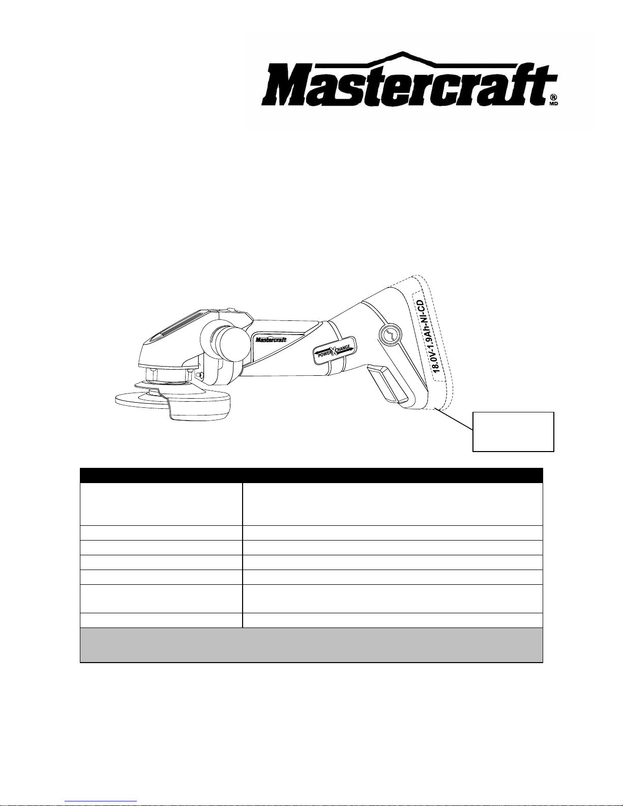
18 V 4½" CORDLESS ANGLE GRINDER
(Battery & Charger Not Included)
054-1245-4
Owner’s Manual
PRODUCT SPECIFICATIONS
Batteries:
18 V
Ni-Cd (054-3102-2; sold separately)
Li-ion (054-3100-6; sold separately)
Speed:
6500 RPM (no load)
Maximum disc diameter:
4½" (115 mm)
Spindle threads:
5
/8" – 11UNC (15.875 mm)
Minimum disc thickness:
5
/32" (3.9 mm)
Chargers:
1-hour, diagnostic (054-3103-0 or 054-3101-4;
both sold separately)
Weight:
6 lb 11 oz (3.04 kg) without battery
NEED ASSISTANCE?
Call us on our toll-free Customer Support Line: 1-800-689-9928
Imported by Mastercraft Canada Toronto, Canada M4S 2B8
Battery not
included
Page 2

2
Product specifications ………….…………………………………………………….
1
Table of contents ……………………………………………………………………...
2
General safety warnings ……………………………………………………………..
3–4
Eye, ear & lung protection ……………………………………………………………
3–4
Electrical safety ……………………………………………………………………….
4
Power tool safety ……………………………………………………………………...
5–7
General safety rules …………………………………………………………………..
5
Work area ………………………………………………………………….…………..
5
Electrical safety ……………………………………………………………………….
5
Personal safety ………………………………………………………………………..
5–6
Use and care of power tools .………………………………………………………..
6
Service …………………………………………………………………………………
6–7
Specific safety rules …………………………………………………………………..
7–8
Battery and charger safety …………………………………………………………..
9
Symbols ………………………………………………………………………………..
10
Know your cordless angle grinder ……………………………………………..
11
Accessories and contents ……………………………………………………………
12–13
Available accessories ………………………………………………………………...
12
Contents ……………………………………………………………………………….
12–13
Assembly and operation ……………………………………………………………..
14–21
Installing the assist handle …………………………………………………………..
14
Installing a battery …………………………………………………………………….
14–15
Installing the guard ……………………………………………………………………
1516
Positioning the guard …………………………………………………………………
16
Installing a grinding disc .…………………………………………………………….
17
ON/OFF switch ………………………………………………………………………..
18–19
Grinding ………………………………………………………………………………..
19–21
Maintenance …………………………………………………………………………..
21
Exploded view …………………………………………………………………………
22
Parts list ………………………………………………………………………………..
23–24
Warranty ……………………………………………………………………….………
25–26
TABLE OF CONTENTS
Page 3
3
EYE, EAR & LUNG PROTECTION
This instruction manual includes the following:
General Safety Rules
Specific Safety Rules and Symbols
Functional Description
Assembly
Operation
Maintenance
Accessories
!
ALWAYS WEAR EYE PROTECTION THAT CONFORMS WITH CSA
REQUIREMENTS or ANSI SAFETY STANDARD Z87.1
FLYING DEBRIS can cause permanent eye damage. Prescription
eyeglasses ARE NOT a replacement for proper eye protection.
WARNING: Non-compliant eyewear can cause serious injury if
broken during the operation of a power tool.
SAVE THESE INSTRUCTIONS FOR REFERENCE
WARNING: Use hearing protection, particularly during extended
periods of operation of the tool, or if the operation is noisy.
!
GENERAL SAFETY WARNINGS
CAUTION: Before using this tool or any of its accessories, read this
manual and follow all Safety Rules and Operating Instructions.
!
Page 4
4
ELECTRICAL SAFETY
WARNING: To avoid electrical hazards, fire hazards or damage to the
tool, use proper circuit protection.
This tool is wired at the factory for 120 V operation. It must be connected to
a 120 V, 15 A circuit that is protected by a time-delayed fuse or circuit
breaker. To avoid shock or fire, replace power cord immediately if it is worn,
cut or damaged in any way.
GENERAL SAFETY WARNINGS
WEAR A DUST MASK THAT IS DESIGNED TO BE USED WHEN
OPERATING A POWER TOOL IN A DUSTY ENVIRONMENT.
WARNING: Dust that is created by power sanding, sawing, grinding,
drilling, and other construction activities may contain chemicals that are
known to cause cancer, birth defects, or other genetic abnormalities. These
chemicals include:
Lead from lead-based paints
Crystalline silica from bricks, cement, and other masonry products
Arsenic and chromium from chemically treated lumber
The level of risk from exposure to these chemicals varies, according to how
often this type of work is performed. In order to reduce exposure to these
chemicals, work in a well-ventilated area, and use approved safety
equipment, such as a dust mask that is specifically designed to filter out
microscopic particles.
!
Page 5

5
GENERAL SAFETY RULES
WARNING: Read and understand
all instructions. Failure to follow all
instructions listed below may result in
electric shock, fire and/or serious personal
injury.
WORK AREA
Keep your work area clean and well lit.
Cluttered benches and dark areas invite
accidents.
Do not operate power tools in potentially
explosive environments, such as in the
presence of flammable liquids, gas or dust.
Power tools create sparks that may ignite
dust or fumes.
Keep bystanders, children and visitors
away while operating the tool. Distractions
can cause the operator to lose control.
ELECTRICAL SAFETY
Double insulated tools are equipped with a
polarized plug (one blade is wider than the
other). This plug will only fit into a
polarized plug one way.
If the plug does not fit into the outlet
properly, reverse the plug. If it still does not
fit, contact a qualified electrician to install a
polarized outlet. Do not alter the plug in
any way. Double insulation eliminates the
need for the three-pronged grounded
power cord and grounded power supply
system.
Avoid contact between the operator's body
and grounded surfaces such as pipes,
radiators, ranges, and refrigerators. There
is an increased risk of electric shock if the
operator's body is grounded.
Do not expose power tools to rain or wet
conditions. Water entering the power tool
will increase the risk of electric shock.
Do not abuse the cord. Do not use the
power cord to carry the tool or to pull the
plug out of the outlet. Keep the power cord
away from heat, oil, sharp edges, and
moving parts. Replace a damaged power
cord immediately. A damaged power cord
increases the risk of electric shock.
When operating a power tool outdoors,
use an outdoor-rated extension cord type
“W-A” or “W”. These cords are rated for
outdoor use and they reduce the risk of
electric shock.
PERSONAL SAFETY
Stay alert, be aware of the surroundings,
and use common sense when operating a
power tool. Do not use a power tool while
tired or under the influence of drugs,
alcohol, or medication. A moment of
inattention while operating a power tool
may result in serious personal injury.
Dress properly. Do not wear loose clothing
or jewellery.
Contain long hair. Keep hair, clothing, and
gloves away from moving parts. Loose
clothing, jewellery, or long hair can get
caught in moving parts.
!
POWER TOOL SAFETY
Page 6

6
PERSONAL SAFETY – cont’d
Avoid accidental start-ups. Verify that the
switch is in the OFF position before
plugging in the tool. Carrying a power tool
with a finger on the switch or plugging in a
tool that has the switch in the ON position
invites accidents.
Remove adjusting keys and wrenches
before turning the tool ON. A wrench or
key that is left attached to a rotating part of
the tool may result in personal injury.
Do not overreach. Keep proper footing and
balance at all times. Proper footing and
balance allows the operator to maintain
better control of the tool in unexpected
situations.
Use safety equipment. Always wear eye
protection.
Use a dust mask, non-skid safety shoes, a
hardhat, or hearing protection when
appropriate.
USE AND CARE OF POWER TOOLS
Use clamps or another practical means to
secure and support the workpiece to a
stable platform. Holding the work in a hand
or against the body is not stable, and may
lead to loss of control.
Do not force the tool. Use the correct tool
for the application. The correct tool will do
the job better and safer when used at the
rate that it was designed to work at.
Do not use a power tool if it cannot be
turned ON or OFF using the power switch.
A tool that cannot be controlled using the
switch is dangerous, and must be repaired.
Disconnect the plug from the outlet before
making any adjustments, changing
accessories, or storing the tool. Such
preventive safety measures reduce the risk
of accidental start-ups.
When power tools are not in use, store
them out of the reach of children or
untrained persons. Tools are dangerous in
the hands of untrained users.
Maintain tools with care. Keep cutting tools
sharp and clean. Properly maintained
cutting tools with sharp cutting edges are
less likely to bind, and are easier to
control.
Inspect the tool for misalignment or binding
of moving parts, broken parts, and any
other condition that may affect the
operation of the tool. If it is damaged, have
the tool serviced before using it. Many
accidents are caused by poorly maintained
tools.
Use only accessories that are
recommended by the manufacturer for this
model. Accessories that are suitable for
one tool may become hazardous when
used with another tool.
SERVICE
Tool servicing must be performed by
qualified personnel. Service or
maintenance performed by non-qualified
personnel could result in a risk of injury.
POWER TOOL SAFETY
Page 7

7
SERVICE – cont’d
When servicing a tool, use only identical
replacement parts. Follow the instructions
in the Maintenance section of this Manual.
The use of unauthorized parts or failure to
follow the instructions in the Maintenance
section of this Manual may create a risk of
electric shock or injury.
WARNING: Know your cordless
angle grinder. Do not plug in the
charger or install a battery in the tool
until you have read and understand this
Instruction Manual. Learn the tool’s
applications and limitations, as well as
the specific potential hazards related to
this tool. Following this rule will reduce the
risk of electric shock, fire, or serious injury.
Always wear eye protection. Any power
tool can throw foreign objects
into your eyes and cause
permanent eye damage.
ALWAYS wear safety goggles
(not glasses) that comply with ANSI safety
standard Z87.1. Everyday glasses have
only impact resistant lenses. They ARE
NOT safety glasses.
WARNING: Glasses or goggles
not in compliance with ANSI Z87.1
could cause serious injury when they
break.
WARNING: Always wear gloves to
protect your hands from hot sparks.
WARNING: Always wear hearing
protection and a dust mask. Use only in
well ventilated areas. Use of personal
protective equipment and working in a safe
environment will reduce the risk of injury.
Always keep hands out of the path of the
grinding disc. Avoid awkward hand
positions where a sudden slip could cause
your hand to move into the rotating disc.
To avoid injury from accidental starting,
always remove the battery from the angle
grinder before installing or removing
grinding discs.
The grinding disc and guard must be
securely attached as described in this
Owner’s Manual before installing a battery
in the tool. Failure to do so will increase
the risk of serious injury if the grinding disc
shatters.
Make sure the guard is in good condition
and securely installed before operating
grinder.
Secure the workpiece. Use clamps or a
vice to hold the work when practical. It’s
safer than using your hand and it frees
both hands to operate the tool.
Do not clamp grinder in vise or use as a
fixed grinder.
Grinding discs must be stored in a dry
location to prevent deterioration.
SPECIFIC SAFETY
RULES
!
!
POWER TOOL SAFETY
!
!
Page 8

8
Before attaching the grinding disc, inspect
it for visible defects. If it is cracked,
chipped or warped do not install it.
Use only grinding discs in compliance with
ANSI Standard B7.1 and rated for a speed
greater than 6,500 RPM.
Do not remove the soft paper in the centre
of the grinding disc.
NOTE: If this paper has been previously
removed, insert some soft rubber or paper
between the grinding disc and the disc
flange to prevent damage to the grinding
disc.
Do not alter or enlarge the centre hole of
the grinding disc as this could result in
breaking it.
Do not over tighten the clamp nut on the
grinding disc. Excessive tightening may
cause the disc to crack and possibly
shatter during operation.
Do not use the grinder if the disc flange or
clamp nut is missing or if the spindle is
bent.
Check to make sure and any extension
cords are clear of the area to be cut.
Contact with ”live” wires could shock the
operator or cause a fire.
Always hold the grinder securely with two
hands while working and at all times when
it is running.
Never turn the grinder ON with the grinding
disc or any rotating parts touching the work
surface.
Never cover the air vents in the motor
housing with your hands while operating
the grinder.
SPECIFIC SAFETY RULES
Page 9

9
Battery packs and chargers must be
purchased separately.
This angle grinder has been designed to
be powered by one of the following battery
packs:
● 18 V Nickel-Cadmium #054-3102-2
● 18 V Lithium-ion #054-3100-6
WARNING: Only use the battery
packs listed above to power this tool.
Using any other battery pack could
cause serious injury or damage the
tool.
Both battery packs can be charged using
one of the following chargers:
● 14.4 V / 18 V LED Diagnostic Battery
Charger #054-3103-0
● 14.4 V / 18 V LCD Diagnostic Battery
Charger with LCD Status Display
#054-3101-4
WARNING: Only use the battery
chargers listed above to charge the
battery packs listed above. Charging
any other batteries may damage the
charger and possibly cause serious
injury.
WARNING: Follow all safety rules
and warnings included with the battery
pack and charger purchased for use
with this tool. Failure to follow those
safety rules and warnings may result in
serious injury or damage to the charger
and battery pack.
Never dispose of defective batteries with
your household waste. Always recycle
defective batteries in accordance with your
local municipal policies.
! ! !
BATTERY AND CHARGER SAFETY
Page 10

10
V
Volts
A
Amperes
Hz
Hertz
W
Watts
kW
Kilowatts
Microfarads
L
Litres
kg
Kilograms
H
Hours
N/cm2
Newtons per square
centimetre
Pa
Pascals
Min
Minutes
S
Seconds
Alternating current
Three-phase alternating
current
Three-phase alternating
current with neutral
Direct current
No load speed
Alternating or direct
current
Class II construction
Splash-proof
construction
Watertight construction
Protective grounding at
grounding terminal,
Class I tools
Revolutions or
reciprocations per
minute
Diameter
Off position
Arrow
Warning symbol
SYMBOLS
WARNING: Some of the following symbols may appear on the cordless
angle grinder. Study these symbols and learn their meaning. Proper
interpretation of these symbols will allow for more efficient and safer
operation of this tool.
!
3042597
LISTED
This symbol designates that this tool is
listed with Canadian requirements by
ETL Testing Laboratories, Inc.
Conforms to UL Std. 60745-1, 60745-2-3.
Certified to CAN/CSA Std. C22.2 No.
60745-1, 60745-2-3.
JD597118
Page 11

11
KNOW YOUR CORDLESS ANGLE GRINDER
NOTE: Battery & Charger are NOT included and must
be purchased separately. This angle grinder is
compatible with all 18 V PowerXchange batteries.
Battery pack
(sold separately)
Battery release
button
Assist
handle
ON/OFF switch
Guard
Spindle locking
button
Inner disc
flange
Disc
Page 12

12
AVAILABLE ACCESSORIES
WARNING: Use only grinding and
cut-off discs that are recommended for
this cordless angle grinder. Follow the
instructions that accompany the
grinding and cut-off discs. The use of
improper discs may result in injury to
the operator or damage to the angle
grinder.
Before using any accessory, carefully read
the instructions or the owner’s manual for
the accessory.
Grinding discs
Cut-off discs
WARNING: If any part is missing or
damaged, do not install a battery in the
tool until the missing or damaged part is
replaced.
CONTENTS
Carefully unpack the cordless angle
grinder. Compare the contents against the
“ANGLE GRINDER COMPONENTS” chart
below.
NOTE: See illustration of the cordless
angle grinder and components on
Page 13.
Battery packs and chargers must be
purchased separately.
This angle grinder has been designed to
be powered by one of the following battery
packs:
● 18 V Nickel-Cadmium #054-3102-2
● 18 V Lithium-ion #054-3100-6
WARNING: Only use the battery
packs listed above to power this tool.
Using any other battery pack could
cause serious injury or damage the
tool.
Both battery packs can be charged using
one of the following chargers:
● 14.4 V / 18 V LED Diagnostic Battery
Charger #054-3103-0
● 14.4 V / 18 V LCD Diagnostic Battery
Charger with LCD Status Display
#054-3101-4
WARNING: Only use the battery
chargers listed above to charge the
battery packs listed above. Charging
any other batteries may damage the
charger and possibly cause serious
injury.
WARNING: Follow all safety rules
and warnings included with the battery
pack and charger purchased for use
with this tool. Failure to follow those
safety rules and warnings may result in
serious injury or damage to the charger
and battery pack.
Never dispose of defective batteries with
your household waste. Always recycle
defective batteries in accordance with your
local municipal policies.
ACCESSORIES AND CONTENTS
!
!
ANGLE GRINDER COMPONENTS
KEY
DESCRIPTION
QTY
A
Angle grinder
1
B
Assist handle
1
C
Grinding disc
1
D
Flange wrench
1
E
Guard
1
F
Outer disc flange
1
G
Inner disc flange
1
Owner’s Manual
1
! ! !
Page 13

13
CONTENTS
Page 14

14
INSTALLING THE ASSIST HANDLE
1. Remove the battery from the angle
grinder.
2. Install the assist handle (1) by
screwing it clockwise into the left side
(2) of the gear housing (3) (Fig. 1).
NOTE: The handle can be installed on
either the left or right side or the top of the
grinder gear housing, depending upon
operator preference (Fig. 6, 7 & 8). The
assist handle must always be used to
prevent loss of control and possible injury.
3. Tighten the assist handle securely.
NOTE: Hand-tighten the side handle. Do
not over tighten.
CHANGING A BATTERY IN THE ANGLE
GRINDER
1. Remove the discharged battery (1)
from the tool by pressing on one the
battery release buttons (2) on the
sides of the tool handle (Fig. 2).
NOTE: There is one battery release button
on each side of the handle. It is only
necessary to press one of the buttons to
release the battery.
2. Pull the battery out of the tool handle
(3).
3. Slide the fully charged battery into the
matching cavity in the tool handle
where the discharged battery has
been removed.
ASSEMBLY AND OPERATING
Fig. 1
Fig. 2
Page 15

15
CHANGING A BATTERY IN THE ANGLE
GRINDER – cont’d
NOTE: Make sure the battery is fully
engaged with the mounting slots in the tool
handle. The battery release buttons will
“click” into place when the battery is fully
installed.
WARNING: Do not immerse the
battery pack in water. Sudden cooling
could cause the hot battery to explode or
leak.
INSTALLING THE GUARD
WARNING: The guard must be
installed before installing a grinding
disc or using the angle grinder. Failure
to do so could result in serious
personal injury.
1. Remove the battery from the angle
grinder.
2. Depress the spindle lock button (1)
(Fig. 3).
3. Rotate the clamp nut (2) until the
spindle locks (Fig. 4).
4. Turn the clamp nut counter clockwise
and remove it from the spindle.
NOTE: If clamp nut cannot be loosened by
hand, use the wrench (3) provided.
5. Remove disc flange (4). It will simply
pull off the spindle (5).
6. Using a #2 Philips® screwdriver,
remove the four guard retainer screws
(6) and four lock washers (7).
!
ASSEMBLY AND OPERATING
!
Fig. 3
Fig. 4
Fig. 2
Page 16

16
INSTALLING THE GUARD – cont’d
7. Lift off the guard retainer washer (8).
8. Place the guard (9) on the gear
housing (10) (Fig. 5).
NOTE: Make sure the hole in guard fits
over the mounting boss (11) on the gear
housing and that the wave crest washer
(12) is in place.
9. Place the guard retainer washer (8) on
the gear housing boss and fasten in
place with the four screws (6) and four
lock washers (7) that were removed.
10. Rotate the guard to position it toward
the rear of the grinder.
11. Tighten all four screws with the screw
driver.
12. Install the disc flange, making sure it
mates with the flats on the spindle.
13. Install the clamp nut finger tight to
hold the disc flange in place.
POSITIONING THE GUARD
WARNING: The guard must be
positioned correctly to protect the
operator. Rotate the guard to the
correct position as noted in Fig. 6, 7 or
8. Guard placement depends upon
where the handle is positioned.
Left side
Right side
Center
ASSEMBLY AND OPERATION ASSEMBLY AND OPERATING
!
Fig. 5
Fig. 6
Handle on
left side
Fig. 7
Handle on
right side
Fig. 8
Handle in
centre
Page 17

17
INSTALLING A GRINDING DISC
WARNING: Use the correct size of
grinding disc. Never use a disc thinner
than 5/32".
1. Depress the spindle lock button and
rotate the outer clamp nut (1) until
spindle locks (Fig. 9).
2. Turn the outer clamp nut counter
clockwise and remove it from the
spindle.
NOTES:
a) If the outer clamp nut (1) cannot be
loosened by hand, use the wrench (2)
provided.
b) DO NOT remove the inner disc flange
(3).
3. Make sure the flats in the inner disc
flange are engaged with the flats on
the spindle.
4. Place the grinding disc (4) over the
spindle (5) with the concave side of
the disc facing out.
5. Screw the outer clamp nut onto the
spindle with the flat side of nut facing
outward away from the disc. Fit the
raised small diameter portion of the
clamp nut into the hole in the grinding
disc.
NOTE: Finger tighten only.
6. Depress the spindle lock button and
rotate the grinding disc clockwise until
the spindle locks.
7. Securely tighten the clamp nut with
the wrench provided
ASSEMBLY AND OPERATING
Fig. 9
!
Page 18

18
WARNING: Have you read “GENERAL SAFETY WARNINGS”, “POWER
TOOL SAFETY”, “SPECIFIC SAFETY RULES”, BATTERY AND CHARGER
SAFETY” and “SYMBOLS” on pages 3, 4, 5, 6, 7, 8, 9 &10 of this Manual? If not,
please do it now before you operate this angle grinder. Your safety depends on
it!
Every time you use the angle grinder you should verify the following:
1. Grinding disc is correct for the type of material being ground
2. Grinding disc is in good condition and securely tightened onto the spindle
3. Proper eye and hearing and breathing protection are being worn.
Failure to adhere to these safety rules can greatly increase the chances of
injury.
WARNING: Never attach a wood
cutting or carving blade of any type to
this angle grinder. It is designed for
grinding metal only. Use for any other
purpose is not recommended and
creates a hazard which will result in
serious injury.
WARNING: Never cover air vents.
They must always be open for proper
motor cooling.
ON/OFF SWITCH
The ON/OFF switch performs three
separate functions:
Lock-off
ON/OFF
Lock-on
ASSEMBLY AND OPERATING
!
!
!
Page 19

19
ON/OFF SWITCH – cont’d
To turn the angle grinder ON:
1. Slide the centre lock-off button (1) to
the right with your thumb (Fig. 10).
2. While holding the lock-off button
toward the right, press forward on the
front of the ON/OFF switch button (2)
until it “snaps” into the ON position..
3. Remove your thumb from the ON/OFF
switch and the tool will stay running.
To turn the angle grinder OFF:
1. Press on the rear portion of the
ON/OFF switch (3). The switch will
“snap” to the OFF position.
GRINDING
Always select and use grinding discs that
are recommended for the material to be
ground. Make sure that the minimum
operating speed of the grinding disc
selected is not less than 6,500 RPM.
Secure all work before beginning the
grinding operation.
Secure small workpieces in a vice or clamp
to a workbench.
WARNING: Never use your angle
grinder with the guard removed. It has
been designed for use only with the
guard installed. Attempting to use the
grinder with the guard removed will
result in loose particles being thrown
against the operator resulting in serious
personal injury.
Fig. 10
ASSEMBLY AND OPERATING
!
Page 20

20
GRINDING – cont’d
WARNING: Never use your angle
grinder without eye protection.
Following this rule will reduce the risk
of serious personal injury.
The efficient operation of the angle grinder
begins by controlling the pressure and
surface contact between the grinding disc
and the workpiece. Flat surfaces are
ground at an acute angle, normally
between 5° and 15° (Fig. 11).
For maximum control, hold the grinder in
front and away from you with both hands,
keeping the grinding disc clear of the
workpiece. Start your grinder and let the
motor and grinding disc build up to full
speed. Gradually lower the grinder until the
grinding disc contacts the workpiece
For best results keep the grinder tilted at
an angle of between 5° and 15° and
continuously moving at a steady,
consistent pace. Move the grinder back
and forth or up and down over the work
area. Keep the grinder moving so that an
excessive amount of material is not
removed from one area. If the grinder is
held in one spot too long, it will gouge and
cut grooves in the workpiece. If the grinder
is held at too sharp an angle, it will gouge
the workpiece because of the
concentration of pressure on a small area.
ASSEMBLY AND OPERATING
!
Fig. 11
5° to 15°
Page 21

21
GRINDING – cont’d
Use just enough pressure to keep the
grinder from chattering or bouncing. Heavy
pressure will decrease its speed and put a
strain on the motor. Normally, the weight of
the tool alone is adequate for most
grinding jobs. Use light pressure when
grinding jagged edges or loose bolts where
there is potential for the grinder to snag on
the metal edge.
Lift the grinder away from the workpiece
before turning it OFF.
WARNING: When servicing, use
only identical replacement parts. Use of
any other part may create a hazard or
cause product damage.
DO NOT abuse power tools. Abusive
practices can damage the tool as well as
the workpiece.
WARNING: DO NOT attempt to
modify tools or create accessories. Any
such alteration or modification is misuse
and could result in a hazardous condition
leading to possible serious injury. It will
also void the warranty.
CLEANING
DO NOT use solvents when cleaning
plastic parts. Most plastics are susceptible
to damage from various types of
commercial solvents and may be damaged
by their use. Use a clean cloth to remove
dirt, dust, oil, grease, etc.
WARNING: Do not at any time
allow brake fluids, gasoline, petroleumbased products, penetrating oils, etc. to
come in contact with plastic parts. They
contain chemicals that can damage,
weaken or destroy plastic.
WARNING: Always wear safety
goggles or safety glasses with side shields
during all grinding operations. It is critical
that you also wear safety goggles or safety
glasses with side shields and a dust mask
while blowing dust out of the angle grinder
with an air jet. Failure to take these safety
precautions could result in permanent eye
or lung damage.
LUBRICATION
All of the bearings in this angle grinder are
lubricated with a sufficient amount of highgrade lubricant for the life of the unit under
normal conditions. Therefore, no further
lubrication is required.
ASSEMBLY AND OPERATING
! ! !
MAINTENANCE
!
Page 22

22
EXPLODED VIEW
51
4
5
36
33
1
2
3
4
5
6
7
8
9
10
11
13
14
12
15
17
16
18
20
19
21
23
24
25
26
27
28
29
30
31
32
34
35
38
37
53
52
48
47
46
43
44
42
41
40
39
57
50
56
45
49
54
55
22
Page 23

23
WARNING: When servicing, use only Mastercraft
®
replacement parts. The use of
any other parts may create a safety hazard or cause damage to the angle grinder.
Any attempt to repair or replace electrical parts on this angle grinder may create a safety
hazard unless repairs are performed by a qualified technician. For more information, call
the Toll-free Helpline, at 1-800-689-9928.
Always order by PART NUMBER, not by key number.
Key #
Part #
Part Name
Quantity
1
216003
Outside flange
1 2 640000
Abrasive wheel
1 3 216004
Inner flange
1
4
6511401012
Screw M4×10
12
5
504003
Spring washer M4
12
6
5403450101
Wheel guard clamp
1 7 221203
Wave washer
1
8
5403460101
Wheel guard
1
9
6100730101
Output spindle
1
10
513001
Woodruff key
1
11
236044
Gear cover
1
12
221204
Washer
1
13
520033
Bearing 6001
1
14
224305
Bearing clamp A
1
15
6516400812
Screw M4x8
2
16
214908
Bevel gear
1
17
215140
Spindle lock pin
1
18
240801
Spring
1
19
511007
Circlip for shaft 9
1
20
521000
Bearing HK0810
1
21
6701040302
Nut
1
22
155517
Spindle lock button
1
23
6597393013
Screw ST3.9×35
2
24
6597392523
Screw ST3.9×25
2
25
5201800101
Gear housing
1
PARTS LIST
!
Page 24

24
Key #
Part #
Part Name
Quantity
26
502000
Nut M6
1
27
214907
Pinion
1
28
520027
Bearing 6000
1
29
224306
Bearing clamp B
1
30
6516400812
Screw M4×8
2
31
6100740101
Drive shaft
1
32
4600750101
Rubber drive link
1
33
500806
Screw ST2.9×8
2
34
5101920101
Drive link tray connector
1
35
5610310101
Fan
1
36
6511500812
Screw M5×8
2
37
5403430101
Spring washer M5
2
38
5403440101
Motor flange
1
39
5800480301
Auxiliary handle
1
40
6100750101
Pin
1
41
4408950101
Switch button
1
42
4408960101
Switch lock button
1
43
5501220101
Spring 1 44
4408980101
Block
1
45
6597292523
Screw ST2.9×25
2
46
2700280101
Switch
1
47
5501230101
Switch spring
1
48
4408970101
Switch slide
1
49
6597391923
Screw ST3.9×19
6
50
4301680201
Right housing
1
51
4404500101
Large pole plate
1
52
3601820101
Button housing
1
53
2000290201
Battery pack
1
54
2500240101
Motor
1
55
4301670201
Left housing
1
56
4406640101
Décor board
1
57
4404510101
Small pole plate
1
PARTS LIST
Page 25

25
3-Year Limited Warranty
This Mastercraft product is guaranteed for a period of 3 years from the date of
original retail purchase against defects in workmanship and materials, except for the
following components:
a) Component A: Batteries, chargers and carrying cases, which are
guaranteed for a period of 2 years from the date of original retail purchase
against defects in workmanship and materials;
b) Component B: Accessories which are guaranteed for a period of 1 year
from the date of original retail purchase against defects in workmanship
and materials.
Subject to the conditions and limitations described below, this product, if returned to
us with proof of purchase within the stated warranty period and if covered under this
warranty, will be repaired or replaced (with the same model, or one of equal value or
specification),at our option. We will bear the cost of any repair or replacement and
any costs of labour relating thereto.
These warranties are subject to the following conditions and limitations:
a) A bill of sale verifying the purchase and purchase date must be provided;
b) This warranty will not apply to any product or part thereof that is worn or
broken or that has become inoperative due to abuse, misuse, accidental
damage, neglect or lack of proper installation, operation or maintenance
(as outlined in the applicable owner’s manual or operating instructions) or
that is being used for industrial, professional, commercial or rental
purposes;
c) This warranty will not apply to normal wear and tear or to expendable parts
or accessories that may be supplied with the product that are expected to
become inoperative or unusable after a reasonable period of use;
d) This warranty will not apply to routine maintenance and consumable items,
including but not limited to fuel, lubricants, vacuum bags, blades, belts,
sandpaper, bits, fluids, tune-ups or adjustments;
e) This warranty will not apply where damage is caused by repairs made or
attempted by others (i.e.: persons not authorized by the manufacturer);
f) This warranty will not apply to any product that was sold to the original
purchaser as a reconditioned or refurbished product (unless otherwise
specified in writing);
Page 1 of 2
Page 26

26
Rev 1.3 11/07/2009
3-Year Limited Warranty – cont’d
These warranties are subject to the following conditions and limitations:
g) This warranty will not apply to any product or part thereof if any part
from another manufacturer is installed therein or any repairs or
alterations have been made or attempted by unauthorized persons;
h) This warranty will not apply to normal deterioration of the exterior
finish including but not limited to scratches, dents, paint chips, or to
any corrosion or discolouring by heat, abrasive and chemical cleaners;
and
i) This warranty will not apply to component parts sold by and identified
as the product of another company, which shall be covered under the
product manufacturer’s warranty, if any.
Additional Limitations
This warranty applies only to the original purchaser, and cannot be transferred.
Neither the retailer nor the manufacturer shall be liable for any other expense, loss
or damage, including but not limited to any indirect, incidental, consequential or
exemplary damages arising in connection with the sale, use or inability to use this
product.
Notice to Consumer
This warranty gives you specific legal rights, and you may have other rights, which
may vary from province to province. The provisions contained in this warranty are
not intended to limit, modify, take away from, disclaim or exclude any statutory
warranties set forth in any applicable provincial or federal legislation.
Mastercraft is a superior line of products selected for their workmanship and
materials. These products are designed to meet rigorous quality and performance
standards, and are approved by our Quality Assurance laboratory.
TOLL-FREE HELPLINE: 1-800-689-9928
Page 2 of 2
 Loading...