

Page 1

INSTRUCTION
MANUAL
IMPORTANT:
Read and understand this instruction manual
thoroughly before using the product.
model no. 054-1232-4
ORBITAL JIGSAW WITH LASER
LINE AND 360° SCROLL CUTTING
Page 2

3
TABLE OF CONTENTS
Technical Specifications 4
Safety Guidelines 5–9
Key Parts Diagram 10–11
Important Information 12–15
Assembly Instructions 16–21
Operating Instructions 22–28
Maintenance 29
Troubleshooting 30
Part list 31–33
Warranty 34–35
NOTE: If any parts are missing or damaged, or if you
have any questions, please call our toll-free helpline at
1-800-689-9928
SAVE THESE INSTRUCTIONS
• This manual contains important safety and
operating instructions. Read all instructions
and follow them with use of this product.
TABLE OF CONTENTS
Page 3

5
4
model no. 054-1232-4 | contact us 1.800.689.9928
TECHNICAL SPECIFICATIONS
Laser Diode Type Red Laser Diode 650 nm
Laser Class
Class Ⅲa, power output ≤2.5 mW
No load Speed 800–3000 SPM
Rated Voltage 120V~, 60Hz
Rated Power Input 6A
Cutting angle range 0–45° left and right
Cutting depth in wood 3 11/32" (85 mm)
Cutting depth in steel 1/4 " (6 mm)
Weight 6 lb 3 oz (2.85 kg)
RULES FOR SAFE OPERATION
KNOW YOUR TOOL
To operate this tool, carefully read this Instruction Manual and all labels affixed to
the Orbital Jigsaw before using. Keep this Manual available for future reference.
IMPORTANT
This tool should only be serviced by a qualified service technician. For more
information, call the toll free helpline at 1-800-689-9928.
READ ALL INSTRUCTIONS CAREFULLY
SAVE THESE INSTRUCTIONS
GENERAL POWER TOOL SAFETY WARNINGS
WARNING!
Read all safety warnings and instructions. Failure to follow the warnings
and instructions may result in electric shock, fire and/or serious injury.
SAVE ALL WARNINGS AND INSTRUCTIONS FOR FUTURE REFERENCE.
The term “power tool” in the warnings refers to your mains-operated (corded)
power tool or battery-operated (cordless) power tool.
WORK AREA SAFETY
• Keep the work area clean and well lit. Cluttered or dark areas invite accidents.
• Do not operate power tools in explosive atmospheres, such as in the presence
of flammable liquids, gases or dust. Power tools create sparks, which may
ignite the dust or fumes.
• Keep children and bystanders away while operating a power tool. Distractions
can cause you to lose control.
ELECTRICAL SAFETY
• Power tool plugs must match the outlet. Never modify the plug in any way. Do
not use any adapter plugs with earthed (grounded) power tools. Unmodified
plugs and matching outlets will reduce the risk of electric shock.
• Avoid body contact with earthed or grounded surfaces such as pipes,
radiators, ranges and refrigerators. There is an increased risk of electric shock
if your body is earthed or grounded.
• Do not expose power tools to rain or wet conditions. Water entering a power
tool will increase the risk of electric shock.
• Do not abuse the cord. Never use the cord for carrying, pulling or unplugging
the power tool. Keep the cord away from heat, oil, sharp edges or moving
parts. Damaged or entangled cords increase the risk of electric shock.
SAFETY GUIDELINES
TECHNICAL SPECIFICATIONS
Page 4

7
6
model no. 054-1232-4 | contact us 1.800.689.9928
• When operating a power tool outdoors, use an extension cord suitable for outdoor
use. Use of a cord suitable for outdoor use reduces the risk of electric shock.
• If operating a power tool in a damp location is unavoidable, use a ground-fault
circuit interrupter (GFCI) protected supply. Use of a GFCI reduces the risk of
electric shock.
PERSONAL SAFETY
• Stay alert, watch what you are doing and use common sense when operating
a power tool. Do not use the tool while tired or under the influence of drugs,
alcohol, or medication. A moment of inattention while operating power tools
may result in serious personal injury.
• Use personal protective equipment. Always wear eye protection. Protective
equipment such as dust mask, non-skid safety shoes, hard hat, or hearing
protection, used for appropriate conditions, will reduce personal injuries.
• Prevent unintentional starting. Ensure the switch is in the off-position before
connecting to power source and/or battery pack, picking up or carrying the
tool. Carrying power tools with your finger on the switch or energising power
tools that have the switch on invites accidents.
• Remove any adjusting key or wrench before turning the power tool on. A
wrench or a key left attached to a rotating part of the power tool may result in
personal injury.
• Do not overreach. Keep proper footing and balance at all times. This enables
better control of the power tool in unexpected situations.
• Dress properly. Do not wear loose clothing or jewellery. Keep your hair,
clothing and gloves away from moving parts. Loose clothes, jewellery or long
hair can be caught in moving parts.
• If devices are provided for the connection of dust extraction and collection
facilities, ensure that these are connected and properly used. Use of these
devices can reduce dust-related hazards.
POWER TOOL USE AND CARE
• Do not force the power tool. Use the correct power tool for your application.
The correct power tool will do the job better and more safely at the rate for
which it was designed.
• Do not use the power tool if the switch does not turn it on and off. Any power
tool that cannot be controlled with the switch is dangerous and must be repaired.
• Disconnect the plug from the power source and/or the battery pack from the
power tool before making any adjustments, changing accessories, or storing
power tools. Such preventive safety measures reduce the risk of starting the
power tool accidentally.
• Store idle power tools out of the reach of children and do not allow persons
unfamiliar with the power tool or these instructions to operate the power tool.
Power tools are dangerous in the hands of untrained users.
• Maintain power tools. Check for misalignment or binding of moving parts,
breakage of parts and any other condition that may affect the power tool’s
operation. If damaged, have the power tool repaired before use. Many
accidents are caused by poorly maintained power tools.
• Keep cutting tools sharp and clean. Properly maintained cutting tools with
sharp cutting edges are less likely to bind and are easier to control.
• Use the power tool, accessories, tool bits, etc. in accordance with these
instructions, taking into account the working conditions and the work to be
performed. Use of the power tool for operations different from those intended
could result in a hazardous situation.
SERVICE
• Have your power tool serviced by a qualified repair person using only
identical replacement parts. This will ensure that the safety of the power tool
is maintained.
SAFETY INSTRUCTIONS FOR LASERS
This orbital jigsaw has a built-in laser light. The laser is a Class Ⅲa and emits
a maximum output power of 2.5 mW at 650 wavelengths. These lasers do not
normally present an optical hazard. However, do not stare at the beam, because
this can cause flash blindness.
The following label is on your tool. It
indicates where the saw emits the laser
light. Be aware of the location of the
laser light when using. Always make sure
that any bystanders in the vicinity of
use are made aware of the dangers of
looking directly into the laser.
WARNING!
Laser light. Laser radiation. Avoid Direct Eye Exposure. Do not stare
into beam. Only turn laser beam on when the saw is on the workpiece.
Class Ⅲa laser.
WARNING!
The use of controls, adjustments or performance of procedures other
than those specified in this manual may result in hazardous radiation
exposure.
WARNING!
The use of optical instruments to view the laser beam, including but not
limited to telescopes or transits, will increase eye hazard.
• Do not remove or deface any product labels. Removing product labels
increases the risk of exposure to laser radiation.
SAFETY GUIDELINES
SAFETY GUIDELINES
Page 5

9
8
model no. 054-1232-4 | contact us 1.800.689.9928
• Protect your hearing. Wear appropriate personal hearing protection during use.
Under some conditions, noise from this product may contribute to hearing loss.
• All visitors and bystanders must wear the same safety equipment required for
the operator.
• Inspect the tool’s power cords periodically,and if they are damaged, have
them repaired by a qualified service technician. Be aware of the location of
the cord.
• Always check the tool for damaged parts. Before using the tool, any guard
or other part that is damaged should be carefully checked to determine
whether it will operate properly and perform its intended function. Check
for misalignment or binding of moving parts, broken parts, and any other
condition that may affect the tool’s operation. A guard or other part that
is damaged should be properly repaired or replaced by a qualified service
technician.
• Inspect and remove all nails from lumber before sawing.
• Save these instructions. Refer to them frequently, and use them to instruct
others who may use this tool. If someone borrows this tool, make sure they
also have these instructions.
• The label on your tool may include the following symbols. The symbols and
their definitions are as follows:
V ..................... Volts
A ..................... Amperes
Hz ................... Hertz
W .................... Watts
min ................. Minutes
............... Alternating current
............. Direct current
n
0
................... No-load speed
............... Class II Construction
…/min ........... Revolutions or reciprocation per minute
............... Grounding terminal
BPM ............... Beats per minute
.............. WARNING – To reduce the risk of injury, user must read
instruction manual.
• The laser beam can be harmful to the eyes. Always avoid direct eye exposure.
Do not look directly into the laser beam output aperture during operation. Do
not project the laser beam directly into the eyes of others. Turn the laser on
only when making cuts.
• The laser on the orbital jigsaw is not a toy. Always keep the tool out of the
reach of children. The laser light emitted from this device should never be
directed toward any person for any reason.
• Be sure the laser beam is aimed at a workpiece (such as wood or rough coated
surfaces) that does not have a reflective surface.
• Do not use on surfaces like sheet steel that have a shiny, reflective surface.
The shiny surface may reflect the beam back at the operator. Be aware that
laser light reflected off a mirror or any other reflective surfaces can also be
dangerous.
• Always turn the laser beam off when not in use. Leaving the tool on increases
the risk of someone inadvertently staring into the laser’s beam.
CAUTION!
Always follow the instructions in this manual when using this laser.
The use of this feature in any manner other than what appears in this
manual may result in hazardous radiation exposure.
• Do not attempt to modify the performance of this laser device in any way. This
may result in a dangerous exposure to laser radiation.
• Use only the accessories that are recommended by manufacturer for use with
this model. The use of accessories that have been designed for use with other
laser tools could result in serious injury.
SAFETY INSTRUCTIONS FOR THE ORBITAL JIGSAW
• Hold the tool by the insulated gripping surfaces (handles) when performing
any operation where the cutting tool may contact hidden wiring or its own
cord. Contact with a “live” wire will make the exposed metal parts of the tool
“live”, and may shock the operator.
• Secure the workpiece before cutting. Never hold a workpiece in your hand or
on your legs. Small or thin material may flex or vibrate with the blade, causing
loss of control.
ADDITIONAL SAFETY INSTRUCTIONS FOR OPERATION
• Know your power tool. Read the Manual carefully. Learn the applications, as
well as the specific potential hazards related to this tool. Following this rule
will reduce the risk of electric shock, fire or serious injury.
• Always wear safety glasses or eye shields when using this saw. Everyday
eyeglasses only have impact-resistant lenses. They are not safety glasses.
• Protect your lungs. Wear a facemask or dust mask if the operation is dusty.
SAFETY GUIDELINES
SAFETY GUIDELINES
Page 6

11
10
model no. 054-1232-4 | contact us 1.800.689.9928
PACKAGE CONTENTS
Orbital jigsaw, wood cutting blade, dust extraction port, edge guide and
instruction manual
KEY PARTS DIAGRAM
3 2 16134
10
6 7819 20
11
15
9
12
1
5
18
17
21
14
NO. PART NO. PART
1 Scrolling control knob 12 Vacuum blower knob
2 On/Off trigger switch 13 Tool-less blade clamp
3 Power Lock-on button 14 Variable-speed dial
4 Release button 15 Scrolling/Orbit control lever
5 Hex wrench 16 Top handle
6 Push-on switch 17 Edge guide
7 Blade storage 18 “Live tool indicator” LED light
8 Bevel-angle scale 19 Edge-guide mounting slot
9 Locking knob for edge guide 20 Base plate
10 Blade guide 21 Laser aperture
11 Laser on/off button
KEY PARTS DIAGRAM
WARNING!
• Remove the orbital jigsaw from the package and examine it carefully.
Do not discard the carton or any packaging material until all parts
have been examined.
• If any part of the orbital jigsaw is missing or damaged, do not plug
the tool in or use it until the part has been repaired or replaced.
Failure to heed this warning could result in serious injury.
KEY PARTS DIAGRAM
Page 7

13
12
model no. 054-1232-4 | contact us 1.800.689.9928
IMPORTANT INFORMATION
Before attempting to use this orbital jigsaw, become familiar with all of its
operating features and safety requirements. For optimum performance and
safety, read the following operating instructions carefully before using the saw.
LED WORKLIGHT
Your orbital jigsaw has a built-in LED worklight for illuminating the cutting area.
To activate the LED worklight, plug in your orbital jigsaw. The LED worklight
turns on automatically when the tool is plugged in to a power source.
LED “LIVE TOOL INDICATOR” LIGHT (g1)
Your orbital jigsaw has a green LED “live
tool indicator” light, located where the
power cord enters the handle. This light
turns on automatically when the saw is
plugged into a power source.
2-WAY SAWDUST REMOVAL
Your orbital jigsaw is equipped with a
2-way sawdust removal system. Push
the vacuum/blower knob to blow debris
away from the cutting area, or attach the
vacuum adapter (fig 2) to a wet/dry vac
hose with a 1 1/2" (38 mm) adapter, all
sold separately.
1. Unplug the saw.
2. Switch the vacuum/blower knob to
the “BLOWER” position in order to
blow sawdust, metal and plastic chips
away from the cutting area.
3. Switch the vacuum/blower knob (fig 3)
to the “VACUUM” position. Connect the
saw’s vacuum adapter to a standard
wet/dry shop vac (sold separately) in
order to vacuum up sawdust, metal and
plastic chips.
ON-BOARD BLADE STORAGE (g4)
A convenient feature on the saw is the
blade storage compartment. The blade
storage compartment is located on either
side of the shoe. To open: pull the blade
storage cover out. To close: push the
cover in with your thumb or finger.
IMPORTANT INFORMATION
IMPORTANT INFORMATION
WARNING!
• Do not allow familiarity with the orbital jigsaw to cause a lack
of alertness. A fraction of a second of carelessness is enough to
cause severe injury.
g1
g2
g4
g3
Blower
switch
Page 8

15
14
model no. 054-1232-4 | contact us 1.800.689.9928
SCROLLING AND ORBITAL ACTION (g5)
• SCROLLING “S”- this mode allows 360°
blade rotation using the scrolling knob.
There is no orbital action in this mode.
Use with a scroll blade to cut intricate
scroll patterns in all materials.
• SMOOTH “0”- for cutting all materials
using the normal up and down blade
motion with minimal splintering. There
is no orbital action in this mode. Use
this mode for cutting hardwoods, mild
steel, soft and hard materials using fine
wood-cutting and smooth metal cutting blades.
• LOW “1”- for cutting most metal, plastics and hardwoods, with a slightly
aggressive orbital action.
• MEDIUM “2”- for cutting most metal, plastics, and hardwoods with a more
aggressive orbital action than the LOW mode.
• FAS T “3”- for maximum orbital action and the fastest cutting speed in
plywood, soft woods and softer materials.
Choose the SCROLLING (S) or SMOOTH (0) setting with the scrolling/orbital
control lever for normal up and down blade motion (position S and 0).
Choose the LOW or MEDIUM settings for the least aggressive orbital blade
actions (positions 1 and 2).
Choose the FAST setting for the fastest, most aggressive cutting with maximum
orbital blade action (position 3).
Position S
SCROLLING
in all
materials.
Position 0
SMOOTH
for reduced in
all materials.
Position 1
Position 2
LOW
for metal.
MEDIUM
for plastics,
hardwoods.
Position 3
FAS T
For maximum
orbital action
and faster
cutting in
plywood and
soft woods.
SCROLLING CONTROL KNOB (g6)
The scrolling feature allows the blade to be
rotated 360°. It is ideal for cutting curves,
designs and detailed pattern work.
1. To engage the scrolling function, move
the scrolling/orbit control lever to the
SCROLLING position (fig 5).
2. Grasp the scrolling control knob (fig 6).
3. The scrolling control knob can be
rotated 360° to the left or right while guiding the saw in order to follow
intricate cutting lines.
IMPORTANT INFORMATION
IMPORTANT INFORMATION
NOTE:
•The blade can be locked into any scrolling position within 360° by switching
the scrolling/orbit control lever to the “SMOOTH” position.
•After moving the lever into the scrolling position, turn the scrolling knob
back and forth to be sure the blade plunger assembly is locked into the
desired position.
•When scroll cutting intricate designs, we recommend that you use a scroll
cutting blade.
•Excessive side pressure on the blade could break the blade, which could
damage the material that is being cut.
NOTE: In order to reach full orbital action, the blade must be facing straight
ahead, and the back of the blade must rest in the groove of the guide
roller. The foot must be positioned all the way forward. Orbital action is not
observable when the saw is free-running. The saw must be cutting in order for
orbital action to occur. The cutting speed is easier to see in thicker materials.
IMPORTANT: When you are scroll cutting with the scrolling control knob,
always hold the saw handle in one hand and rotate the scrolling knob with the
other hand while applying pressure to the front of the saw so that it does not
jump out of the workpiece.
g5
g6
Page 9

17
16
model no. 054-1232-4 | contact us 1.800.689.9928
ASSEMBLY INSTRUCTIONS
ATTACHING THE TOP HANDLE TO
THE ORBITAL JIGSAW (g7)
1. Align and slide the rear bottom of the
top handle with the attaching plate
compartment.
2. Slide the top handle onto the attaching
plate compartment, and hold down the
handle-release buttons until the top
handle snaps and locks into place (fig 7).
TOOL-LESS BLADE INSTALLATION (g8)
The tool-less blade change control allows
you to remove and replace the saw blade
quickly and easily, without the use of
additional tools.
1. Unplug the saw.
2. Raise the clear chip shield, lift one side
of its mounting slot, and remove the
shield from the saw. Apply slight force
when lifting and removing the shield
from the saw.
3. Turn the saw upside down so that you can access the blade clamp.
4. Depress the tool-less blade-change lever. Insert the blade directly into the
slot of the tool-less blade change holder (fig 8). The teeth of the blade should
be facing the front and pointing up (when saw is right side up, in cutting
position), and the back of the blade must rest in the groove of the blade
guide rollers.
5. Pull the blade to make sure it is securely locked in place.
ASSEMBLY INSTRUCTIONS
CAUTION!
• Once the blade is installed in the saw, it is always exposed. There
is no lower blade guard. Use caution when handling the saw so
that the blade does not catch clothing, skin, etc. Each time you
set the saw down, take care not to bend the blade. Always set
the saw down on its side when the blade is installed. Always
remove the blade when saw is not being used.
WARNING!
• Make sure the push-on switch is OFF when attaching the top
handle to the orbital jigsaw.
g7
NOTE: The push-on switch cannot be switched on when the top handle is on
the orbital jigsaw.
NOTE: For use with both “T” &”U” shanked blades.
ASSEMBLY INSTRUCTIONS
g8
Blade
Blade
Guide
Rollers
Page 10

19
18
model no. 054-1232-4 | contact us 1.800.689.9928
REMOVING THE BLADE (g9)
1. Unplug the saw.
2. Raise the clear chip shield, lift one side
of its mounting slot, and remove the
shield from the saw. Apply slight force
when lifting and removing the shield
from the saw.
3. Turn the saw upside down so that you
can access the blade clamp.
4. Depress the tool-less blade-change lever (fig 9)
5. Carefully remove the blade.
6. Reattach the clear chip shield, and snap it down to its proper position.
ADJUSTING THE CUTTING SPEED
WITH THE VARIABLE-SPEED DIAL
(g10)
The variable speed feature of this orbital
jigsaw allows you to match the proper
cutting speed to the material being cut,
enhancing the overall performance of
your saw and helping to save the blades
from undue wear.
1. The variable-speed dial is used to
adjust the speed of the blade.
2. Turn the dial to increase or decrease the speed of the blade (fig 10).
3. Position “1” selects the slowest blade speed, position “6” selects the fastest
blade speed. Adjust blade speed for optimum performance.
WORKPIECE TO BE CUT NUMBER ON THE VARIABLE-SPEED DIAL
Wood 5–6
Mild steel 2–5
Stainless steel 3–4
Aluminium 3–6
Plastic 1–4
ASSEMBLY INSTRUCTIONS
ASSEMBLY INSTRUCTIONS
g9
WARNING!
• Failure to unplug the saw from the power source when
assembling parts, making adjustments or changing blades could
result in accidental starting causing possible serious injury.
NOTE: Determine the optimum speed for cutting your workpiece by making
a trial cut in a scrap piece of material. Your experience will determine the
best results for a particular application. However, as a general rule, use slower
speeds for harder, denser materials and faster speeds for soft materials.
g10
Page 11

21
20
model no. 054-1232-4 | contact us 1.800.689.9928
ADJUSTING THE BASE PLATE FOR
BEVEL CUTTING (gs11,12)
1. Unplug the saw and remove the blade.
2. To adjust the cutting angle, first turn
the tool upside down and pull the dust
extraction port to remove it from the
tool.
3. Use the hex key to loosen the hex
screw securing the saw base.
4. Move the base of the saw slightly
forward, and tilt it to the required
angle, between 0° and 45°, using the
scale marked on the base bracket.
5. Install a cutting blade.
6. Slide the blade guide assembly until
the blade guide rests against the back
edge of the blade.
7. Re-tighten the hex screws. For accurate
work, it is necessary to make a trial cut,
measure the work, and reset the angle until the correct setting is achieved.
USING THE EDGE GUIDE (g13)
The edge guide (included) is used for
straight cutting:
1. Insert the bar of the edge guide
through the slots in the base of the
orbital jigsaw. It can be inserted from
either side of the base, with the edge
guide facing down.
2. Screw the edge-guide locking knob
into the threaded hole in the base in
order to tighten the edge-guide bar in
place.
3. Measure the distance from the edge
of the workpiece to the cutting line.
Slide the edge guide to this desired
distance, and tighten the locking knob
in order to secure the edge guide in
place (fig 14).
CAUTION!
• Always remove the blade before adjusting the cutting angle.
• In order to prevent damage to the tool when angle or bevel
cutting, the scroll mechanism must be locked in place, with the
cutting edge of the blade facing the front of the tool.
WARNING!
• Do not let familiarity with your saw make you careless. Remember
that a fraction of a second of carelessness is sufficient to cause
severe injury.
g11
g13
g14
WARNING!
• Always unplug the saw from the power source before making
any adjustment or attaching accessories.
ASSEMBLY INSTRUCTIONS
ASSEMBLY INSTRUCTIONS
g12
Page 12
23
22
model no. 054-1232-4 | contact us 1.800.689.9928
OPERATING INSTRUCTIONS
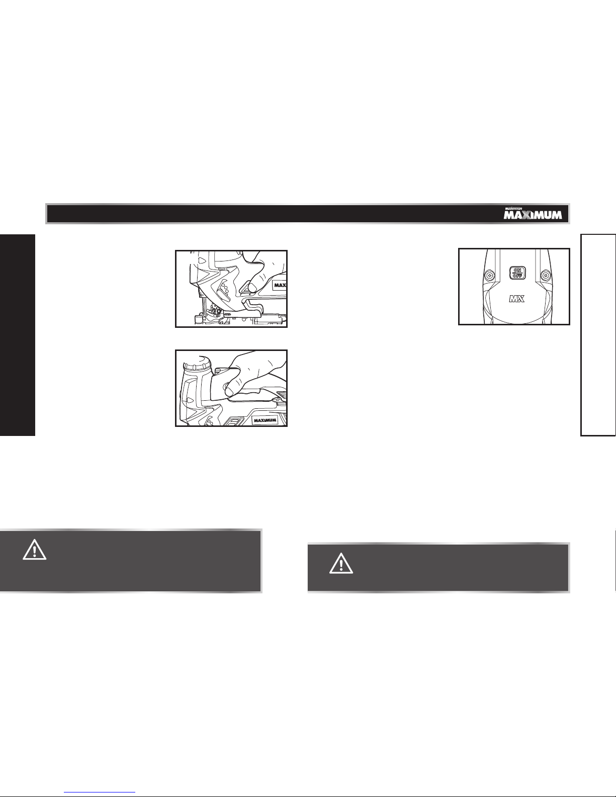
TURNING THE SAW ON-OFF WHEN
BARREL GRIPPING THE ORBITAL
JIGSAW(g15)
1. Connect the power cord of your saw to
a standard household power outlet.
2. Turn your saw on by sliding the pushon switch forward until it clicks into the
start position.
3. To turn the power off, press in on the
rear section of the push-on switch to stop the tool.
TURNING THE POWER ON/OFF AND
USING THE LOCK-ON BUTTON WHEN
USING THE TOP HANDLE (g16)
1. Connect the power cord of your saw to
a standard household power outlet.
2. Start the tool by squeezing the on/off
trigger switch.
3. Release the on/off trigger switch to
stop the tool.
4. To lock the on/off trigger switch in the “on” position, press the trigger
switch, and press in the lock-on button from either side while holding it “on”.
The power lock-on button allows the operator to keep the orbital jigsaw
running without squeezing the trigger switch. This feature is convenient for
continuous sawing applications.
5. To release the lock-on button, press and release the trigger switch.
USING THE LASER LIGHT FEATURE (g17)
Your orbital jigsaw has a built-in laser
light. To activate the laser, plug in your
orbital jigsaw and press the laser ON/OFF
button.
1. Mark the cutting line on the workpiece.
2. Adjust the cutting angle and cutting
speed as needed.
3. Plug in the saw and push the laser
button to turn on the laser.
4. Align the laser beam with the cutting line.
5. Turn on the trigger switch, and slowly push the saw forward, keeping the laser
beam on the cutting line.
6. Shut off the laser light when finish cutting.
g17
CAUTION!
• Do not let familiarity with your saw make you careless. Remember
that a fraction of a second of carelessness is sufficient to cause
severe injury.
WARNING!
• If the “lock-on” button is depressed continuously, the trigger
cannot be released.
WARNING!
• Laser light. Laser radiation. Avoid direct eye exposure. Do not
stare into beam. Only turn laser beam on when the tool is on the
workpiece. Class IIIa.
• Do not using the laser on reflective surfaces.
OPERATING INSTRUCTIONS
OPERATING INSTRUCTIONS
g15
g16
Page 13

25
24
model no. 054-1232-4 | contact us 1.800.689.9928
GENERAL CUTTING TIPS
1. Always place the best or “finished” side of the workpiece “face down” so that
it does not get scraped or abused while sawing. Always clamp the workpiece
securely before sawing.
2. Draw your cutting lines, patterns or designs on the “backside”, facing you.
This means that they should be reversed or backwards from the way they will
appear on the “finished” side.
3. Always select the correct blade for your cutting application.
4. Place the front edge of the saw base on the material to be cut, and line up
the blade with your cutting line, but do not allow the blade to contact the
workpiece.
5. Hold the saw firmly and turn it on.
6. Press down (to keep the saw foot flat against the workpiece) as you slowly
push the saw in the direction of the cut.
7. Gradually build up the blade speed, cutting as close to the line as possible
(unless you wish to leave enough room for finishing sanding).
8. You may need to reposition the vise or clamps as you cut in order to keep the
workpiece stable.
9. Do not force the saw, because the blade teeth may rub and wear without
cutting, which may result in breaking the blade.
10. Let the saw do most of the work.
11. Always cut slowly when following curves, so that the blade can cut through
cross grain. This will provide an accurate cut, and will prevent the blade from
wandering.
CUTTING METAL
When cutting metal, always clamp down the metal workpiece and use a metal
cutting blade. Be extremely careful to move the saw very slowly as you cut. Use
the low speeds (position 1, 2 or 3 on the variable-speed dial). Also use the LOW
position on the orbital control lever.
Do not twist, bend or force the blade. If the saw jumps or bounces as you cut,
change to a blade with finer teeth. If the blade begins to clog when cutting soft
metal, change to a blade with coarser teeth.
For easier cutting, lubricate the blade with a stick of cutting wax (if available)
or cutting oil when cutting steel. Thin metal should be sandwiched between two
pieces of wood, or tightly clamped onto a single piece of wood (the wood on
top of the metal). Draw the cutting lines or design on the top piece of wood.
When cutting aluminium extrusion or angle iron, clamp the work in a bench
vise and saw close to the vise jaws. When sawing tubing with a diameter that is
larger than the depth of the blade, cut through the wall of the tubing and then
insert the blade into the cut, rotating the tube as you saw.
Spread the oil onto the blade or workpiece at regular intervals during cutting in
order to reduce wear or overheating of the blade.
NOTE: Always apply a steady, firm “DOWNWARD” pressure on the front and
body of the saw as you cut. This will keep the saw blade from jumping out of
the workpiece.
WARNING!
• Always unplug the saw from the power source before oiling the
blade or making any adjustments or attaching accessories.
• Always clamp and secure workpiece securely. Always maintain
proper control of the saw. Failure to clamp and support the
workpiece and loss of control of the saw could result in serious
injury.
OPERATING INSTRUCTIONS
OPERATING INSTRUCTIONS
Page 14

27
26
model no. 054-1232-4 | contact us 1.800.689.9928
CUTTING WITH A STRAIGHTEDGE (g18)
1. Mark the cutting line. Position the
straightedge parallel to the cutting
line, at the same distance as between
the blade and the side edge of the saw
base.
2. Mark the side edge of the saw base,
and then clamp the straightedge on
the mark, parallel to the cut.
3. As you cut, keep the edge of the saw
base flush against the straightedge and
flat on the workpiece.
PLUNGE CUTTING (g19)
Plunge cutting is useful and timesaving
for making rough openings in soft
materials. It makes it unnecessary to drill
a hole for an inside or pocket cut.
1. Draw lines for the opening you want to
cut.
2. Hold the saw firmly, and tilt it forward
so that the toe of the saw foot rests on
the workpiece.
3. Make sure that the blade is well clear of the workpiece.
4. Start the saw and then gradually lower the blade into the workpiece, firmly
holding the toe of the saw base in order to prevent side wobble.
5. Slowly pivot the saw downward, as if on a hinge, until the blade cuts through
and the base rests flat on the workpiece.
6. Begin sawing along the cutting line in the usual manner.
MAKING SHARP CORNERS
1. Cut up to the corner, and then back up slightly before rounding the corner.
2. After the opening is complete, go back to each corner and cut it from the
opposite direction in order to square it off.
WARNING!
• To avoid accidents, always disconnect the tool from the power
source before making any adjustments or attaching accessories.
• Do not let familiarity with your saw make you careless. Remember
that a fraction of a second of carelessness is sufficient to cause
severe injury.
• Always wear safety goggles or safety glasses when operating this
tool.
NOTE: Always use a rough-cut blade whenever possible.
g19
WARNING!
• Do not use a scroll blade for plunge cutting.
• Do not try to plunge cut into hard materials, such as hardwoods
like oak or maple, or metal such as steel.
OPERATING INSTRUCTIONS
OPERATING INSTRUCTIONS
g18
Straightedge
Page 15

29
28
model no. 054-1232-4 | contact us 1.800.689.9928
CUTTING CIRCLES (g20)
This requires using a circle cutting/
straight edge guide (sold separately).
1. Before attaching the edge guide, draw
a circle and drill a hole in the centre of
the circle.
2. Drill or plunge cut near the edge of the
circle.
3. Turn the saw off, and disconnect the
plug from power source.
4. Attach the edge guide to the saw (the same way you attached the included
edge guide), with the edge guide facing up.
5. Place the metal centre point on the edge into the hole in the centre of the
circle. In order for the edge guide to cut a circle, the metal centre point must
be aligned with the saw blade.
6. Measure the distance from the selected hole to the blade. This distance is
equal to the radius of the circle.
7. Insert the saw’s plug into a power source.
8. Hold the saw firmly, squeeze the trigger switch, and slowly push the saw
forward.
MAINTENANCE
BEFORE EACH USE:
•Inspect the orbital jigsaw, the on/off switch, and the cord for damage.
•Check for damaged, missing, or worn parts.
•Check for loose screws, misalignment or binding of moving parts, or any other
condition that may affect the operation.
•If abnormal vibration or noise occurs, turn the saw off immediately, and have
the problem corrected before further use. Unplug the saw from the socket
before cleaning or performing any maintenance. Using compressed air may
be the most effective cleaning method. Always wear safety goggles when
cleaning tools using compressed air.
•If the power cord is damaged, it must be replaced with an identical
replacement part and be installed by an authorized service technician.
g20
NOTE: To make a hole, cut from inside the circle. To make wheels or discs,
cut from outside the circle.
WARNING!
• Do not let brake fluids, gasoline, petroleum-based products,
penetrating oil, etc. come into contact with plastic parts. These
substances contain chemicals that can damage, weaken, or
destroy plastic.
• When servicing, use only identical replacement parts. The use
of any other parts may create a hazard or cause damage to the
product.
• Use only accessories that are recommended for this saw by the
manufacturer. Accessories that may be suitable for one tool may
become hazardous when used with another tool.
• Maintain tools with care. Keep cutting tools sharp and clean.
Properly maintained tools with sharp cutting edges are less
likely to bind, and are easier to control.
• To ensure safety and reliability, all repairs should be performed
by a qualified service technician.
MAINTENANCE
OPERATING INSTRUCTIONS
Page 16

31
30
model no. 054-1232-4 | contact us 1.800.689.9928
TROUBLESHOOTING
Problem Cause of the Problem
Suggested Corrective
Action
Laser line is not
projected
Laser switch is not
turned on or the tool isn’t
plunged in
Make sure the tool is
plugged in and the laser
switch is turned on
Laser line is hard
to see
Working condition is too
bright
Use laser-enhancing glasses
(available separately)
LED worklight does
not light
The tool isn’t plunged in
Make sure the tool is
plugged in
The scrolling control
cannot be turned
The Orbit/Scrolling lever
is not in the “Scrolling”
position
Set the lever in the
“Scrolling” position
If the problem remains unsolved after performing the checks described above,
call the toll-free helpline at 1-800-689-9928.
EXPLODED VIEW
WARNING!
• Turn the ON/OFF switch to the “OFF” position and unplug the
saw from the power source before performing troubleshooting
procedures.
PART LIST
TROUBLESHOOTING
Page 17

33
32
model no. 054-1232-4 | contact us 1.800.689.9928
No. Part No. Description No. Part No. Description
1 3320601000
Left Housing
Assembly
28 3320103000 Knob Set
2 3420338000 Left Alum Cover 29 3320104000 Knob Assembly
3 3320616000 Push Button 30 3551339000 Bush
4 3121037000 Cord Guard 31 3420945000 Alum Cover
5 4810002000
Power Cord &
Plug
32 5610022000 Tapping Screw
6 5680019000
Hexagon
Wrench
33 3120477000 Bearing Holder
7 3320819000
Left Handle
Assembly
34 3520055000
Aligning
Bearing
8 3320820000
Right Handle
Assembly
35 5610106000 Tapping Screw
9 3660030000 Spring 36 3420946000 Drive Bracket
10 3123857000 Lock Pin 37 3520057000
Lower Sliding
Bearing
11 3320615000 Lock Button 38 3420129000
Sliding Bearing
Support
12 3121459000 Switch Cover 39 5610021000 Tapping Screw
13 3420675000 Hander Lever 40 5650001000 Plain Washer
14 3320105000 Switch Lock A 41 3120444000 Dust Seal
15 3660072000 Spring 42 3120491000 Guiding Block
16 3123856000 Trigger Lock 43 3550213000 Pendulum Pin
17 3120457000 Limiting Piece 44 3660071000 Spring
18 3660054000 Spring 45 3550202000 Pin
19 3700220000
Connecting
Piece
46 3550191000 Pin 1
20 3121471000 Pendulum Lever 47 2822446000
Plunger
Assembly
21 3700536000 Felt Ring 48 3550214000 Crank Roller
22 3700145000 Washer 49 5700022000 Needle Bearing
23 5660027000
Circlips For
Shaft
50 5660007000
Circlips For
Shaft
24 3660050000 Spring B 51 3700183000 Washer C
25 3700191000 Cap 52 3550993000 Gear Set
26 5610040000 Tapping Screw 53 5700030000 Needle Bearing
27 2822669000 Link Assembly 54 3700203000 Washer 1
No. Part No. Description No. Part No. Description
55 3520058000 Pendulum Plate 80 3660055000
Carbon brush
Spring
56 3700224000
Counterweight
A
81 4870043000 Switch
57 3700225000 Counterweight 82 4890524000 PCB Assembly
58 3700226000 Washer 83 4930004000 Connecter
59 3700184000 Washer D 84 3123861000
Left Indictor
Cover
60 2820588000
Bearing Support
Assembly
85 4540017000
Power Supply
Indicator
61 5700045000 Steel Ball 86 3123860000
Right Indictor
Cover
62 3120016000 Spring Tube 87 3320248000 Vacuum Adapter
63 5620064000 Screw 88 3700675000 Rip Fence
64 3700227000 Washer 89 3124066000 Blade Storage
65 3550201000 Located Pin 90 3420814000 Base Plate
66 2822593000
Roller Support
Set
91 3124065000 Base Plate Cover
67 3400175000 Knob 93 3700236000 Clamp Washer
68 5610079000
Thread Forming
Screw
94 5620013000
Hexagon Socket
Screw
69 3123859000 Switch Actuator 95 3320602000
Right Housing
Assembly
70 3123858000 Lever 96 2822242000 Blowing Knob
71 3660051000 Spring 97 3420339000
Right Alum
Cover
72 3123855000 Link 98 3650099000 Wire Guard
73 2750897000 Rotor 99 3121368000 Guard
74 3700164000 Square Nut 100 3123507000 Transparent Cap
75 2740270000 Stator 101 4360001000 LED
76 5610024000 Tapping Screw 102 2780030000 Laser Set
77 3120234000 Cord Anchorage 103 4890523000 PCB Assembly
78 4960017000 Carbon Brush 104 5700011000 Ball Bearing
79 2820587000
Brush Support
Assembly
105 5700004000 Ball Bearing
If the problem remains unsolved after performing the checks described above,
call the toll-free helpline at 1-800-689-9928.
PART LIST
PART LIST
Page 18

35
34
model no. 054-1232-4 | contact us 1.800.689.9928
5-YEAR LIMITED WARRANTY
This Mastercraft Maximum product is guaranteed against defects
in workmanship and materials for a period of 5 years from the
date of original retail purchase, with the exception of the following
components:
a) Component A: Batteries, chargers and carrying case, which are
guaranteed against defects in workmanship and materials for a
period of 2 years from the date of original retail purchase;
b) Component B: Accessories, which are guaranteed against
defects in workmanship and materials for a period of 1 year
from the date of original retail purchase.
Subject to the conditions and limitations described below, this product, if
returned to us with proof of purchase within the stated warranty period, and if
covered under this warranty, will be repaired or replaced (with the same model
or one of equal value or specification), at our option. We will bear the cost of
any repair or replacement and any labour costs relating thereto.
This warranty is subject to the following conditions and limitations:
a) A bill of sale verifying the purchase and purchase date must be provided;
b) This warranty will not apply to any product or part thereof that is worn or
broken, or that has become inoperative due to abuse, misuse, accidental
damage, neglect or lack of proper installation, operation or maintenance (as
outlined in the applicable owner’s manual or operating instructions), or that is
being used for industrial, professional, commercial or rental purposes;
c) This warranty will not apply to normal wear and tear or to expendable parts
or accessories that may be supplied with the product and that are expected
to become inoperative or unusable after a reasonable period of use;
d) This warranty will not apply to routine maintenance and consumable items,
including but not limited to fuel, lubricants, vacuum bags, blades, belts,
sandpaper, bits, fluids, tune-ups or adjustments;
e) This warranty will not apply where damage is caused by repairs made or
attempted by others (i.e.: persons not authorized by the manufacturer);
f) This warranty will not apply to any product that was sold to the original
purchaser as a reconditioned or refurbished product (unless otherwise
specified in writing);
g) This warranty will not apply to any product or part thereof if any part from
another manufacturer is installed therein or if any repairs or alterations have
been made or attempted by unauthorized persons;
h) This warranty will not apply to normal deterioration of the exterior finish,
including but not limited to scratches, dents, paint chips, or to any corrosion
or discolouring by heat, abrasive and chemical cleaners; and
i) This warranty will not apply to component parts sold by and identified as
the product of another company, which shall be covered under the product
manufacturer’s warranty, if any.
Additional Limitations
This warranty applies only to the original purchaser, and may not be transferred.
Neither the retailer nor the manufacturer shall be liable for any other
expense, loss or damage, including but not limited to any indirect, incidental,
consequential or exemplary damages arising in connection with the sale, use or
inability to use this product.
Notice to Consumer
This warranty gives you specific legal rights, and you may have other rights,
which may vary from province to province. The provisions contained in this
warranty are not intended to limit, modify, take away from, disclaim or exclude
any statutory warranties set forth in any applicable provincial or federal
legislation.
IMPORTED BY MASTERCRAFT CANADA TORONTO, CANADA M4S 2B8
WARRANTY
WARRANTY
Page 19

 Loading...