

Page 1
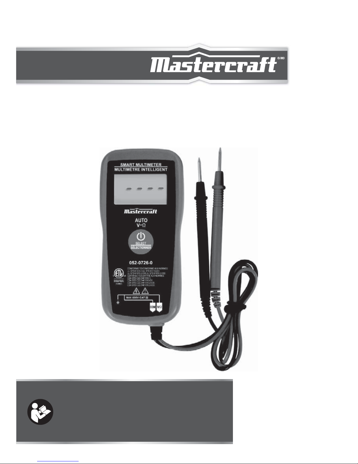
SMART
MULTIMETER
INSTRUCTION
MANUAL
model no. 052-0726-0
Read and understand this instruction manual thoroughly before
using the product. It contains important information for your
safety as well as operating and maintenance advice.
Keep this instruction manual for future use. Should this product
be passed on to a third party, then this instruction manual must
be included.
Page 2

SMART MULTIMETER 052-0726-0
Page 3
To avoid possible electric shock or personal injury, follow these
guidelines:
WARNING
●
●
●
●
●
●
●
●
Do not use the meter if it is damaged. Before you use the
meter, inspect the case. Pay particular attention to the insulation
surrounding the connectors.
Inspect the test leads for damaged insulation or exposed metal.
Check the test leads for continuity. Replace damaged test leads
before you use the meter.
Do not use the meter if it operates abnormally. Protection may
be impaired. When in doubt, have the meter serviced.
Do not operate the meter where explosive gas, vapour, or dust is
present.
Do not apply more than the rated voltage, as marked on the
meter, between the probes or between any probe and earth
ground.
Before use, verify the meter's operation by measuring a known
voltage.
When servicing the meter, use only specified replacement parts.
Use caution when working with voltage above 30 V AC RMS, 42
V peak, or 60 V DC. Such voltages pose a shock hazard.
SAFETY INFORMATION
The multimeter has been designed according to IEC 61010 concerning electronic measuring instruments with a measurement category
(CAT III 600V) and pollution degree 2.
2
WARNING
Page 4

model no. 052-0726-0 | contact us 1-800-689-9928
3
WARNING
●
●
●
●
●
●
●
●
When using the probes, keep your fingers behind the finger
guards on the probes.
When making connections, connect the black test lead before
you connect the red test lead. When you disconnect test leads,
disconnect the red test lead first.
Remove the test leads from the circuit under test before you
open the back cover.
Do not operate the meter with the back cover removed or
loosened.
To avoid false readings, which could lead to possible electric
shock or personal injury, replace the button cells as soon as the
low battery indicator ( ) appears.
To avoid electric shock, do not touch any naked conductor with
your hand or skin, and do not ground yourself while using the
meter.
When a probe is connected to dangerous live potential, it is to
be noted that this potential can occur at the other probe!
CAT III
– Measurement Category III is for measurements
performed in the building installation. Examples are
measurements on distribution boards, circuit breakers, wiring,
including cables,bus-bars, junction boxes, switches,
socket-outlets in the fixed installation, and equipment for
industrial use and some other equipment, for example,
stationary motors with permanent connection to the fixed
installation.
Do not use the meter for measurements within Measurement
Categories IV.
Page 5

4
CAUTION
To avoid possible damage to the meter or to the equipment under
test, follow these guidelines:
Disconnect circuit power and discharge all capacitors before
testing resistance, capacitance or continuity.
Use the proper function for your measurements.
Before pressing the "SELECT" key to change function, disconnect
the test leads from the circuit under test.
CAUTION
●
●
●
Page 6
This meter is a compact 3 5/6-digit digital multimeter for measuring
DC and AC voltage, resistance, frequency, capacitance and continuity. In addition, non-contact AC voltage detection function is also
provided. The meter is operated through a key. In Auto Check mode,
the meter automatically selects measurement function of DC
voltage, AC voltage, or resistance based on the input via the test
leads. It features small size and lightness, and it is easy to operate.
Alternating current
Direct current
Caution, risk of danger. Refer to the operating manual before
use.
Caution, risk of electric shock.
Earth (ground) terminal
Conforms to European Union directives
The equipment is protected throughout by double insulation or
reinforced insulation.
INTRODUCTION
ELECTRICAL SYMBOLS
model no. 052-0726-0 | contact us 1-800-689-9928
5
INTRODUCTION
Page 7
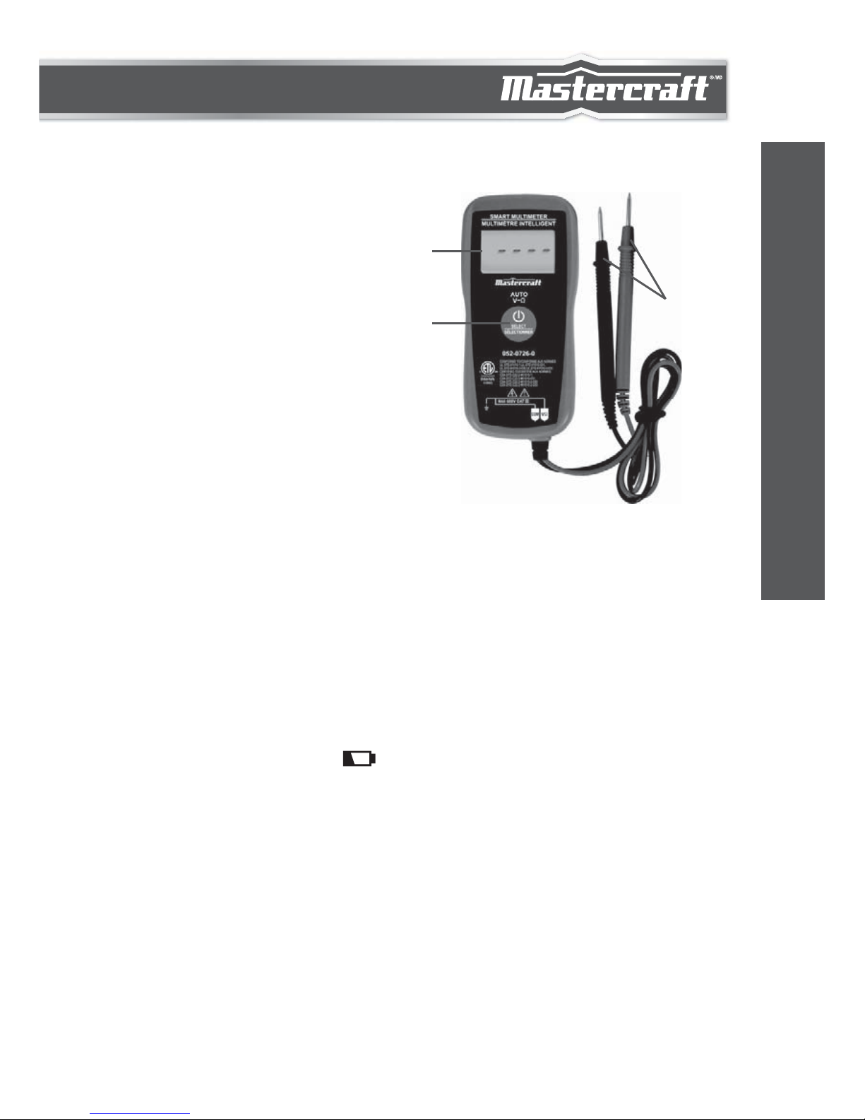
FRONT PANEL
1.
2.
3.
Display
3 5/6-digit LCD, with a max.
reading of 5999.
"SELECT" Key
Used to select desired function
or mode as well as to turn on
or off the meter.
Test Probes
1
2
3
GENERAL SPECIFICATION:
3 5/6-digit LCD, with a max. reading of 5999.
Negative Polarity Indication: Negative sign " - " shown
on the display automatically
Overrange Indication: "OL" shown on the display
Sampling Rate: About 2 to 3 times/sec
Battery: 1.5 V button cell, LR44 or equivalent, 2 pieces
Low Battery Indication: " " shown on the display
Operation Environment: Temperature: 32 to 104ºF (0 to 40ºC)
Relative Humidity: < 75%
Storage Temperature: Temperature: 14 to 122ºF (-10 to 50ºC)
Relative Humidity: < 85%
Operating Altitude: 0 – 6560' (0 – 2000 m)
Size: 4 7/16 x 2 1/8 x 1/2" (112 x 54 x 12 mm) (for main body only)
Weight: About 2 1/2 oz (70 g) (including button cell)
Figure 1
6
INTRODUCTION
Page 8
SPECIFICATIONS
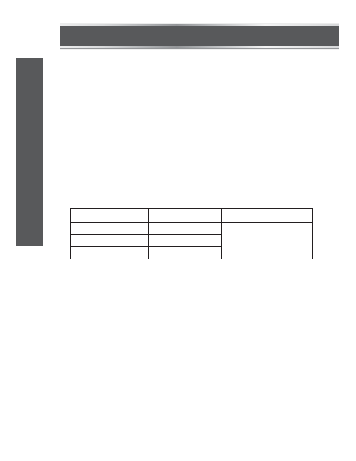
DC VOLTAGE
Readings are accurate for a period of 1 year after calibration at
64 to 82ºF (18 to 28ºC), with relative humidity up to 75%.
Accuracy specifications take the form of:
± [(% of Reading) + (Number of Least Significant Digits)]
Input Impedance: 10 MΩ
Max. Allowable Input Voltage: 600 V
Note: In Auto Check mode, the minimum input DC voltage
required for DC voltage measurement is 1.2 V.
RANGE
6 V 0.001 V
±(0.8% + 3)0.01 V
0.1 V
60 V
600 V
RESOLUTION ACCURACY
model no. 052-0726-0 | contact us 1-800-689-9928
7
TECHNICAL SPECIFICATIONS
Page 9
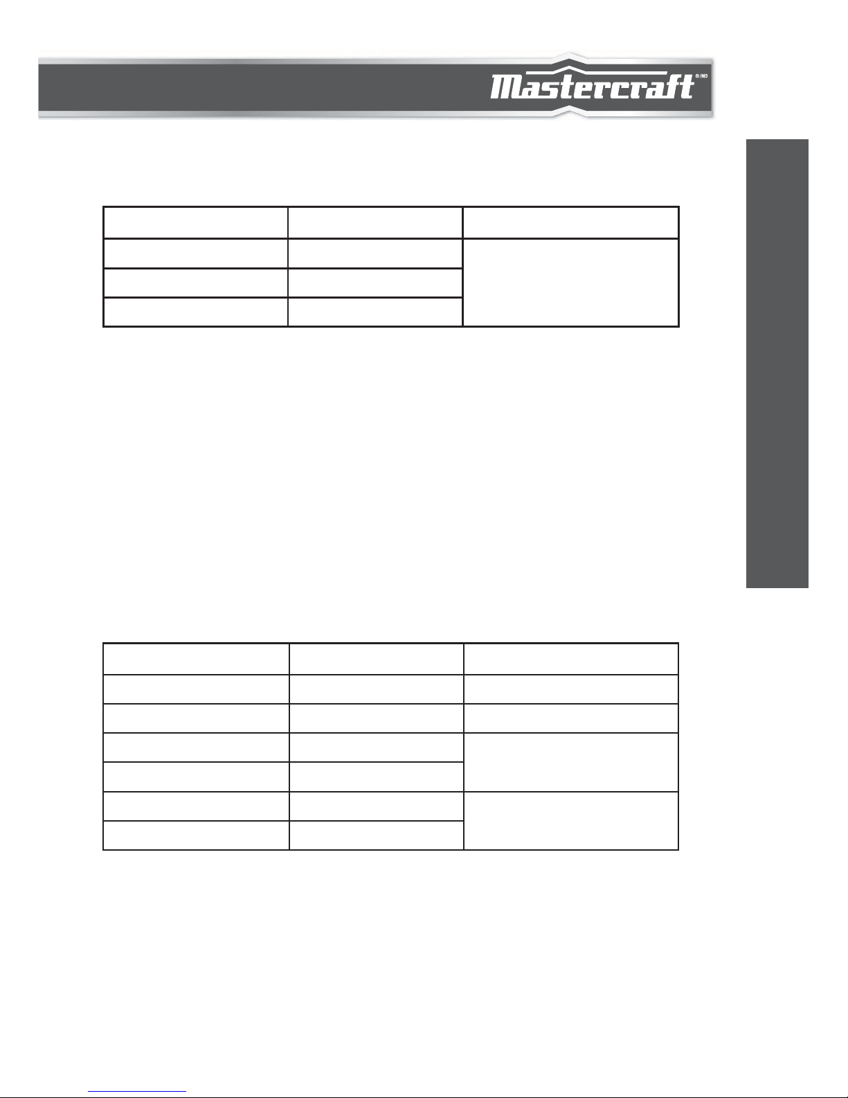
AC VOLTAGE
RESISTANCE
Input Impedance: 10 MΩ
Frequency Range: 40 – 400 Hz
Max. Allowable Input Voltage: 600 V
Response: Average, calibrated in RMS of sine wave
Note: In Auto Check mode, the minimum input AC voltage
required for AC voltage measurement is 1.5 V.
Open Circuit Voltage: About 0.7 V
RANGE
6 V
600 Ω 0.1 Ω
0.001 kΩ
0.01 kΩ
0.1 kΩ
0.001 MΩ
0.01 MΩ
6 kΩ
60 kΩ
600 kΩ
6 MΩ
10 MΩ
0.001 V
±(1.0% + 5)
±(2.0% + 10)
±(1.2% + 6)
±(1.0% + 4)
±(2.0% + 4)
0.01 V
0.1 V
60 V
600 V
RESOLUTION ACCURACY
RANGE RESOLUTION ACCURACY
8
TECHNICAL SPECIFICATIONS
Page 10
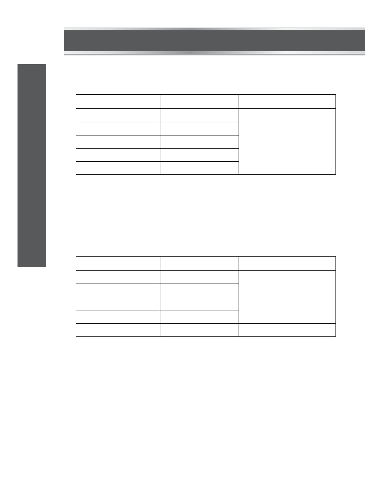
CAPACITANCE
NON-CONTACT AC VOLTAGE DETECTION
Measurement Range: 1 nF – 100 F
Detection Range: 50 – 600 V
Frequency Response: 50/60 Hz
40 nF 0.01 nF
0.1 nF
0.001 F
0.01 F
0.1 F
400 nF
4 F
40 F
100 F
±(4.0% + 5)
±(5.0% + 5)
RANGE RESOLUTION ACCURACY
FREQUENCY
Input Voltage: 1 – 20 V RMS
Measurement Range: 1 Hz – 100 kHz
10 Hz 0.001 Hz
0.01 Hz
0.1 Hz
0.001 kHz
0.01 kHz
100 Hz
1 kHz
10 kHz
100 kHz
±(1.0% + 4 )
RANGE RESOLUTION ACCURACY
model no. 052-0726-0 | contact us 1-800-689-9928
9
TECHNICAL SPECIFICATIONS
Page 11
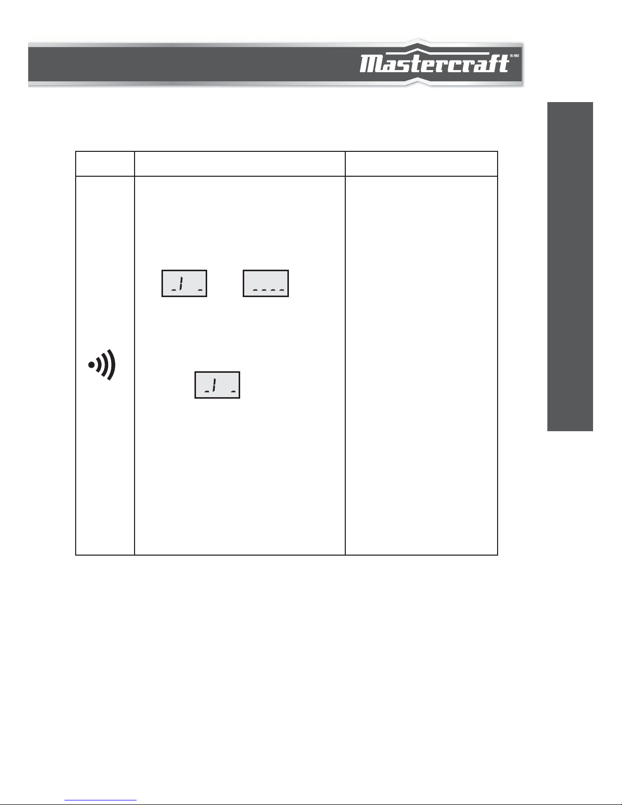
CONTINUITY TEST
RANGE RESOLUTION ACCURACY
If the resistance is less than
about 50 , the built-in buzzer
will sound continuously and
the display will change from
" " to " ".
If the resistance is more than
150 , the buzzer will not
sound and the display will
show " ".
If the resistance is between
50 and 150 , the buzzer
may or may not sound and the
display will change with the
buzzer's behavior.
Open Circuit Voltage:
about 0.7 V
10
ITECHNICAL SPECIFICATIONS
Page 12

NOTE:
The meter has a process of initialization before it enters
non-contact AC voltage detection mode. During this process,
the meter will not respond if you press the "SELECT" key. Only
after the process finishes (the display shows " " and the
built-in buzzer does not sound) can you press the "SELECT"
key to change meter function.
Instruction for the "SELECT" Key
Press and hold down the "SELECT" key for about 3 secs to turn on
the meter. The meter enters Auto Check mode.
In Auto Check mode, press the "SELECT" key to step through the
functions:
Auto Check mode (default) → continuity test →
non-contact AC voltage detection → AC voltage measurement →
DC voltage measurement → resistance measurement →
frequency measurement → capacitance measurement →
Auto Check mode.
Pressing and holding down the "SELECT" key for about 3 secs will
turn off the meter.
OPERATING INSTRUCTIONS
model no. 052-0726-0 | contact us 1-800-689-9928
11
OPERATING INSTRUCTIONS
Page 13

AUTO CHECK MODE
1.
2.
3.
4.
In Auto Check mode, the meter automatically selects measurement
function of DC voltage, AC voltage or resistance based on the input
via the test leads.
With no input, the display shows " ".
With no voltage signal, but a resistance below 10 M present,
the meter displays the resistance value.
When a signal ≥ DC 1.2 V or AC 1.5 V is present, the display
shows the voltage value in DC or AC, whichever larger in peak
magnitude.
Overload Alarm:
When the input voltage is ≥ 610 V, the built-in buzzer will
sound beeps and the display will show "OL".
12
OPERATING INSTRUCTIONS
Page 14
CONTINUITY TEST FUNCTION
In Auto Check mode, press the "SELECT" key once to select continuity test function.
Connect the test leads across the circuit to be tested.
If the resistance is more than 150 , the built-in buzzer will not
sound, and the display will show " ".
If the resistance is less than about 50 , the buzzer will sound
continuously and the display will change from " " to
" ".
If the resistance is between 50 and 150 , the buzzer may or may
not sound and the display will change with the buzzer's behavior.
Before test, disconnect all power to the circuit to be tested and
discharge all capacitors thoroughly.
NOTE:
model no. 052-0726-0 | contact us 1-800-689-9928
13
OPERATING INSTRUCTIONS
Page 15

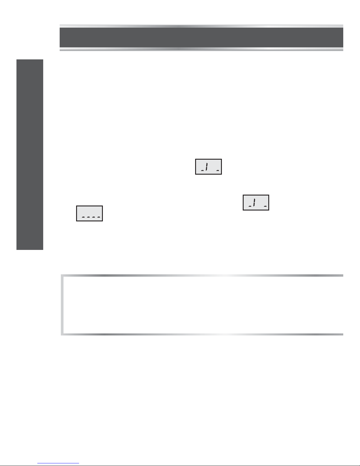
NON-CONTACT AC VOLTAGE DETECTION
In Auto Check mode, press the "SELECT" key twice. The built-in
buzzer sounds beeps, and the four bar-graph segments, which will
be are used to indicate the intensity of electrical field, appear
sequentially at the centre of the display from left to right of the
display (Figure 2). Then the four bar-graph segments drop to lower
positions of the display (Figure 3). Now the buzzer stop sounding and
the meter is in the non-contact AC voltage detection mode.
Move the left top corner of the meter close to the object to be tested.
When the meter detects an electric field generated by AC voltage, the
meter will indicate the intensity of the electrical field as described as
follows:
The intensity of the electrical field is indicated by the number of the
bar-graph segments at the centre of the display and the beeping rate
of the built-in buzzer. The higher the intensity of the detected electric
field, the larger the number of the bar-graph segments (which
appear at the centre of the display), and the faster the beeping rate
of the buzzer.
FIGURE 2 FIGURE 3
14
OPERATING INSTRUCTIONS
Page 16

AC VOLTAGE MEASUREMENT FUNCTION
In Auto Check mode, press the "SELECT" key three times to select
AC voltage measurement function. The display will show the symbol
" " and voltage measurement unit.
Connect the test leads across the source or circuit to be tested. Read
the voltage reading on the display.
Detection Range: 50 – 600 V
Frequency Response: 50/60 Hz
The left top corner of the meter (marked "EF" at the rear of the
meter) is the optimum position of the meter for non-contact AC
voltage detections.
The meter's electric field intensity indication is affected by the
magnitude of the AC voltage of the conductor under test, the
distance between the meter and the conductor, the insulation of
the conductor, etc.
Because of the meter's detection limit, a line (or conductor)
under test may be live even if the meter does not indicate the
presence of electric field.
Before use, verify the meter's operation by detecting a known
AC voltage.
To avoid electric shock, do not touch any conductor with hand or
skin.
NOTE:
1.
2.
3.
4.
5.
6.
model no. 052-0726-0 | contact us 1-800-689-9928
15
OPERATING INSTRUCTIONS
Page 17

DC VOLTAGE MEASUREMENT FUNCTION
In Auto Check mode, press the "SELECT" key four times to select
DC voltage measurement function. The display will show the symbol
" " and voltage measurement unit.
Connect the test leads across the source or circuit to be tested. Read
the voltage reading on the display. The polarity of the red lead
connection will be indicated as well.
NOTE:
NOTE:
Measurement Range: 0 – 600 V AC
To avoid personal electric shock and damage to the meter, do
not connect the meter to a voltage higher than 600 V.
When the input voltage is ≥ 610 V, the built-in buzzer will
sound beeps and the display will show "OL".
1.
2.
3.
Measurement Range: 0 – 600 V DC.
To avoid personal electric shock and damage to the meter, do
not connect the meter to a voltage higher than 600 V.
When the input voltage is ≥ 610 V, the built-in buzzer will
sound beeps and the display will show "OL".
1.
2.
3.
16
OPERATING INSTRUCTIONS
Page 18

RESISTANCE MEASUREMENT FUNCTION
In Auto Check mode, press the "SELECT" key five times to select
resistance measurement function. The display will show resistance
measurement unit.
Connect the test leads across the object to be tested. Wait until the
reading is stable, then read the resistance reading on the display.
For measurements > 1 M, the meter may take a few seconds
to
stabilize reading. This is normal for high resistance measurements.
When the test leads are open, "OL" will be displayed as an
overrange indication.
Before measurement, disconnect all power to the circuit to be
tested and discharge all capacitors thoroughly.
1.
2.
3.
NOTE:
model no. 052-0726-0 | contact us 1-800-689-9928
17
OPERATING INSTRUCTIONS
Page 19

FREQUENCY MEASUREMENT FUNCTION
In Auto Check mode, press the "SELECT" key six times to select
frequency measurement function, the display will show frequency
measurement unit.
Connect the test leads across the source or circuit to be tested. Read
the frequency reading on the display.
Input Voltage Range: 1 – 20 V RMS.
Measurement Range: 1 Hz – 100 kHz
In Auto Check mode, press the "SELECT" key seven times to select
capacitance measurement function, the display will show capacitance
measurement unit.
Thoroughly discharge the capacitor to be tested by shorting its two
leads together. Then connect the test leads to the two leads of the
capacitor. Wait until the reading is stable, then read the capacitance
reading on the display.
NOTE:
Capacitance Measurement Function
18
OPERATING INSTRUCTIONS
Page 20

1.2.Measurement Range: 1 nF – 100 F.
Because the meter measures capacitance by measuring the
time of charging and discharging the capacitor, measuring a
higher capacitance will take more time.
The meter will turn off automatically if you have not operated the
meter for about 15 minutes. The built-in buzzer will sound several
beeps about 1 minute before it turns off automatically and will sound
a beep before it turns off automatically.
NOTE:
Automatic Power-Off
model no. 052-0726-0 | contact us 1-800-689-9928
19
OPERATING INSTRUCTIONS
Page 21

Except replacing button cells, never attempt to repair or service the
meter unless you are qualified to do so and have the relevant
calibration, performance test, and service instructions.
Periodically wipe the case with a damp cloth and mild detergent. Do
not use abrasives or solvents.
1.
2.
3.
This instruction sheet is subject to change without notice.
Our company will not take responsibility for any loss.
The contents of this instruction sheet can not be used as the
reason to use the meter for any special application.
NOTE:
MAINTENANCE
MAINTENANCE
BUTTON CELL REPLACEMENT
When the symbol " " appears on the display, the button cells are
low and must be replaced immediately.
To replace the button cells, remove the screw on the back cover and
remove the back cover. Replace the exhausted button cells with new
ones of the same type (1.5 V button cell, LR44 or equivalent). Make
sure that the polarity connections are correct (see the indication of
the bottom of each button cell compartment). Reinstall the back
cover and the screw.
20
MAINTENANCE
Page 22

DISPOSAL OF THIS ARTICLE
Dear Customer,
If you at some point intend to dispose of this article,
then please keep in mind that many of its
components consist of valuable materials, which
can be recycled.
Please do not dispose of it in the garbage bin, but
check with your local council for recycling facilities
in your area.
This Mastercraft product carries a one-year warranty against defects
in workmanship and materials. This product is not guaranteed
against wear, breakage or misuse.
WARRANTY
model no. 052-0726-0 | contact us 1-800-689-9928
21
WARRANTY
Page 23

ÉLIMINATION DU PRODUIT
Chers clients,
Si vous avez l'intention à un moment donné de jeter
cet article, alors veuillez garder à l'esprit qu'un bon
nombre de ses composants sont constitués de
matériaux précieux, qui peuvent être recyclés.
Veuillez ne pas le jeter à la poubelle, mais consultez
votre conseil municipal pour connaître les installa-
tions de recyclage dans votre région.
GARANTIE
Cet article Mastercraft comprend une garantie de un (1) an contre les
défauts de fabrication et de matériau(x). Exclusion : usure ou bris
causés par un usage abusif ou inapproprié.
21
GARANTIE
N° de modèle : 052-0726-0 | Communiquez avec nous au 1 800 689-9928
Page 24

À l'exception du remplacement des piles boutons, n'essayez pas de
réparer le multimètre par vous-même, à moins que vous soyez
qualifié pour le faire et que vous ayez les instructions relatives à la
calibration, au test de fonctionnement et à la réparation.
Essuyez le boîtier périodiquement avec un chiffon humide et un
nettoyant doux. N'utilisez pas d'abrasifs ou de solvants.
1.
2.
3.
Ce guide d'utilisation est modifiable sans préavis.
Notre société n'est pas responsable en cas de perte.
Le contenu de ce guide ne peut être appliqué pour utiliser le
multimètre de toute autre manière que ce soit.
Remarque :
ENTRETIEN
REMPLACEMENT DES
PILES BOUTONS
Lorsque le symbole « » s'affiche à l'écran, cela signifie que les
piles boutons sont faibles et doivent être remplacées immédiatement.
Pour remplacer les piles boutons, retirez la vis sur le couvercle
arrière, puis retirez le couvercle arrière. Remplacez les piles boutons
usagées par des piles de même type (1,5 V, LR44 ou équivalent).
Assurez-vous de faire correspondre les polarités (voir les symboles
dans le compartiment des piles). Replacez le couvercle arrière et la
vis.
20
ENTRETIEN
Page 25

1.
2.
Gamme de lecture : 1 nF – 100 F.
Du fait que le multimètre indique la capacité en mesurant le
temps de charge et de décharge du condensateur, il lui faudra
plus de temps pour mesurer une capacité élevée.
Le multimètre s'éteindra automatiquement si vous ne l'utilisez pas
pendant environ 15 minutes. L'alarme intégrée émettra plusieurs
bips environ 1 minute avant l'arrêt automatique et émettra un
dernier bip juste avant l'arrêt complet de l'appareil.
Remarque :
ARRÊT AUTOMATIQUE
19
CONSIGNES D’UTILISATION
N° de modèle : 052-0726-0 | Communiquez avec nous au 1 800 689-9928
Page 26

MESURE DE LA FRÉQUENCE
En mode Vérification automatique, appuyez sur la touche
SÉLECTIONNER
« »
six fois pour sélectionner la fonction Mesure de la
fréquence. L'écran affichera l'unité de mesure de la fréquence.
Branchez les fils d'essai dans la source ou le circuit à vérifier. Lisez
la fréquence affichée sur l'écran.
Gamme de tension d'entrée : 1- 20 V RMS
Gamme de lecture : 1 Hz-100 kHz
En mode Vérification automatique, appuyez sur la touche « » SÉLECTIONNER
sept fois pour sélectionner la fonction Mesure de la capacité. L'écran
affichera l'unité de mesure de la capacité.
Déchargez soigneusement le condensateur à vérifier en court-circuitant
ses deux fils ensemble. Connectez ensuite les fils d'essai aux deux
fils du condensateur. Attendez que le résultat affiché soit stable.
Remarque :
MESURE DE LA CAPACITÉ
18
CONSIGNES D’UTILISATION
Page 27

MESURE DE LA RÉSISTANCE
Remarque :
En mode Vérification automatique, appuyez sur la touche
SÉLECTIONNER
« »
cinq fois pour sélectionner la fonction Mesure
de la résistance. L'écran affichera l'unité de mesure de la résistance.
Branchez les fils d'essai sur l'objet à tester. Attendez que le résultat
affiché soit stable.
Pour les mesures supérieures à 1 M, il se peut que le
multimètre ait besoin de quelques secondes pour se stabiliser.
Ce comportement est normal lorsque des résistances élevées
sont mesurées.
Lorsque les fils d'essai sont ouverts, « OL » s'affiche pour
signaler un dépassement.
Avant de procéder à une mesure, coupez le circuit électrique et
déchargez soigneusement tous les condensateurs.
1.
2.
3.
17
CONSIGNES D’UTILISATION
N° de modèle : 052-0726-0 | Communiquez avec nous au 1 800 689-9928
Page 28

MESURE DE LA TENSION CC
En mode Vérification automatique, appuyez sur la touche
SÉLECTIONNER
« »
quatre fois pour sélectionner la fonction Mesure de
la tension CC. L'écran affichera le symbole « » et l'unité de mesure de
la tension.
Branchez les fils d'essai dans la source ou le circuit à vérifier. Lisez
la tension affichée sur l'écran. La polarité du fil d'essai rouge sera
également indiquée.
Remarque :
Remarque :
Gamme de lecture : 0-600 V CA
Pour éviter de recevoir un choc électrique ou d'endommager le
multimètre, ne branchez pas le multimètre sur une tension
supérieure à 600 V.
Lorsque la tension d'entrée est ≥ 610 V, l'alarme intégrée
retentira et l'écran indiquera « OL ».
1.
2.
3.
Gamme de lecture : 0-600 V CC
Pour éviter de recevoir un choc électrique ou d'endommager le
multimètre, ne branchez pas le multimètre sur une tension
supérieure à 600 V.
Lorsque la tension d'entrée est ≥ 610 V, l'alarme intégrée
retentira et l'écran indiquera « OL ».
1.
2.
3.
16
CONSIGNES D’UTILISATION
Page 29

MESURE DE LA TENSION CA
En mode Vérification automatique, appuyez sur la touche
SÉLECTIONNER
« »
trois fois pour sélectionner la fonction Mesure
de la tension CA. L'écran affichera le symbole « » et l'unité de
mesure de la tension.
Branchez les fils d'essai dans la source ou le circuit à vérifier. Lisez
la tension affichée sur l'écran.
Gamme de détection : 50-600 V
Réponse de fréquence : 50/60 Hz
Le coin supérieur gauche du multimètre (près de l'inscription « EF »)
est l'endroit optimal pour effectuer des détections de tension CA
sans contact.
L'intensité du champ électrique est affectée par l'amplitude de
la tension CA du conducteur testé, par la distance entre le
multimètre et le conducteur, par l'isolation du conducteur, etc.
En raison des limites de détection du multimètre, il se peut
qu'une ligne (ou un conducteur) testée soit sous tension alors
que le multimètre n'indique aucune présence de champ
électrique.
Avant d'utiliser le multimètre, vérifiez qu'il fonctionne en
détectant une tension CA connue.
Pour éviter tout choc électrique, ne touchez aucun fil conducteur
avec la main ou la peau.
Remarque :
1.
2.
3.
4.
5.
6.
15
CONSIGNES D’UTILISATION
N° de modèle : 052-0726-0 | Communiquez avec nous au 1 800 689-9928
Page 30

DÉTECTION DE TENSION CA SANS CONTACT
En mode Vérification automatique, appuyez sur la touche « »
SÉLECTIONNER
deux fois. L'alarme intégrée émet des bips et les quatre barres, où
s'affiche habituellement l'intensité du champ électrique, apparais-
sent ensuite au centre de l'écran, de gauche à droite (figure 2). Les
quatre barres s'affichent ensuite au bas de l'écran (figure 3). À
présent, l'alarme cesse de sonner et le multimètre entre en mode
Détection de tension CA sans contact.
Placez l'angle supérieur gauche du multimètre près de l'objet à
tester. Lorsque le multimètre détecte un champ électrique de tension
CA, il indique l'intensité du champ de la façon suivante :
L'intensité du champ électrique s'affiche à la place des quatre barres
centrales et l'alarme émet des bips plus ou moins rapides selon
l'intensité. Plus l'intensité du champ électrique est forte, plus le
chiffre affiché au centre de l'écran sera élevé et la cadence des bips
émis par l'alarme sera rapide.
FIGURE 2 FIGURE 3
14
CONSIGNES D’UTILISATION
Page 31

TEST DE CONTINUITÉ
En mode Vérification automatique, appuyez sur la touche « »
SÉLECTIONNER
une fois pour sélectionner la fonction Test de continuité.
Branchez les fils d'essai sur le circuit à tester.
Si la résistance est supérieure à 150 , l'alarme intégrée ne retentira
pas et l'écran affichera « ».
Si la résistance est inférieure à environ 50 , l'alarme intégrée
retentira en continu et l'affichage de l'écran passera de « » à
« ».
Si la résistance se situe entre 50 et 150 , l'alarme retentira ou
non et l'affichage sur l'écran changera en conséquence.
Avant de procéder à la vérification, coupez le circuit électrique et
déchargez soigneusement tous les condensateurs.
Remarque :
13
CONSIGNES D’UTILISATION
N° de modèle : 052-0726-0 | Communiquez avec nous au 1 800 689-9928
Page 32

MODE VÉRIFICATION AUTOMATIQUE
1.
2.
3.
4.
En mode Vérification automatique, le multimètre sélectionne
automatiquement la mesure parmi la tension CC, la tension CA ou
la résistance en fonction du branchement, grâce aux fils d'essai.
Lorsque rien n'est branché, l'écran affiche « ».
Sans signal de tension, mais avec une résistance inférieure à 10 M,
le multimètre indique la résistance.
Lorsqu'un signal ≥ 1,2 V CC ou 1,5 V CA est présent, l'écran
indique la tension en CC ou CA (celle dont l'amplitude est la plus
élevée).
Alarme de surcharge :
Lorsque la tension d'entrée est ≥ 610 V, l'alarme intégrée
retentira et l'écran indiquera « OL ».
12
CONSIGNES D’UTILISATION
Page 33

Remarque :
Le multimètre passe par une procédure d'initialisation avant
d'entrer en mode Détection de la tension CA sans contact.
Durant cette initialisation, le multimètre ne répondra pas si
vous appuyez sur la touche «
SÉLECTIONNER ». Ce n'est qu'une fois
l'initialisation terminée (lorsque l'écran affiche « » et que
l'alarme ne sonne plus) que vous pouvez appuyer sur la
touche «
SÉLECTIONNER
» pour changer de fonction.
Utilisation de la touche « SÉLECTIONNER »
Maintenez la touche «
SÉLECTIONNER
» enfoncée pendant environ 3
secondes pour allumer le multimètre. Le multimètre passe en mode
Vérification automatique.
En mode Vérification automatique, appuyez sur la touche «
»
SÉLECTIONNER
pour passer d'une fonction à l'autre :
Mode Vérification automatique (par défaut) → test de continuité →
détection de la tension CA sans contact →
mesure de la tension CA → mesure de la tension CC →
mesure de la résistance → mesure de la fréquence →
mesure de la capacité → mode Vérification automatique.
Maintenez la touche «
SÉLECTIONNER
» enfoncée pendant environ 3
secondes pour éteindre le multimètre.
CONSIGNES D’UTILISATION
11
CONSIGNES D’UTILISATION
N° de modèle : 052-0726-0 | Communiquez avec nous au 1 800 689-9928
Page 34

Si la résistance est inférieure à
environ 50 , l'alarme intégrée
retentira en continu et
l'affichage
de l'écran passera
de « » à « ».
Si la résistance est supérieure
à 150 , l'alarme ne retentira
pas et l'écran affichera
« ».
Si la résistance se situe entre
50 et 150 , l'alarme
retentira ou non et l'affichage
sur l'écran changera en
conséquence.
TEST DE CONTINUITÉ
CALIBRE
RÉSOLUTION PRÉCISION
Tension en circuit
ouvert : environ 0,7 V
10
FICHE TECHNIQUE
Page 35

CAPACITÉ
DÉTECTION DE TENSION CA SANS CONTACT
Gamme de lecture : 1 nF – 100 F
Gamme de détection : 50-600 V
Réponse de fréquence : 50/60 Hz
40 nF 0,01 nF
0,1 nF
0,001 F
0,01 F
0,1F
400 nF
4 F
40 F
100 F
± (4,0 % + 5)
± (5,0 % + 5)
CALIBRE RÉSOLUTION PRÉCISION
FREQUENCY
Tension à l'entrée : 1-20 V RMS
Gamme de lecture : 1-100 kHz
10 Hz 0,001 Hz
0,01Hz
0,1 Hz
0,001 kHz
0,01 kHz
100 Hz
1 kHz
10 kHz
100 kHz
± (1,0 % + 4)
CALIBRE RÉSOLUTION PRÉCISION
9
FICHE TECHNIQUE
N° de modèle : 052-0726-0 | Communiquez avec nous au 1 800 689-9928
Page 36

TENSION CA
RÉSISTANCE
Impédance d'entrée : 10 MΩ
Gamme de fréquences : 40-400 Hz
Tension d'entrée maximale autorisée : 600 V
Réponse : moyenne, calibrée en RMS d'onde sinusoïdale
Remarque : En mode Vérification automatique, la tension d'entrée
CA requise au minimum pour être mesurée est de 1,5V.
Tension à circuit ouvert : environ 0,7 V
CALIBRE
6 V
600 Ω 0,1
0,001 k
0,01 kΩ
0,1 k
0,001 M
0,01 M
6 kΩ
60 kΩ
600 kΩ
6 MΩ
10 MΩ
0,001 V
± (1,0 % + 5)
± (2,0 % + 10)
± (1,2 % + 6)
± (1,0 % + 4)
± (2,0 % + 4)
0,01 V
0,1 V
60 V
600 V
RÉSOLUTION PRÉCISION
CALIBRE RÉSOLUTION PRÉCISION
8
FICHE TECHNIQUE
Page 37

CARACTÉRISTIQUES
TENSION CC
Les relevés sont précis pendant une période d'un an après un
étalonnage des températures de 18 à 28 °C (de 64 à 82 °F), avec une
humidité relative allant jusqu'à 75 %.
Les caractéristiques d'exactitude prennent la forme suivante :
± [(% du relevé) + (Nombre de chiffres les moins significatifs)]
Impédance d'entrée : 10 MΩ
Tension d'entrée maximale autorisée : 600 V
Remarque : En mode Vérification automatique, la tension d'entrée
CC requise au minimum pour être mesurée est de 1,2 V.
CALIBRE
6 V 0,001 V
± (0,8 % + 3)0,01 V
0,1 V
60 V
600 V
RÉSOLUTION PRÉCISION
Dimensions du boîtier seulement : 112 x 54 x 12 mm
(4 7/16 x 2 1/8 x 1/2 po)
Poids (pile incluse) : environ 70 g (2 1/2)
7
FICHE TECHNIQUE
N° de modèle : 052-0726-0 | Communiquez avec nous au 1 800 689-9928
Page 38

PANNEAU AVANT
1.
2.
3.
Écran
Écran ACL 3 5/6 chiffres avec
lecture jusqu'à 5 999 points.
Touche « SÉLECTIONNER »
Sert à sélectionner la fonction
et le mode désirés, et à mettre
en marche/arrêter le multimètre.
Sondes de vérification
1
2
3
GÉNÉRALITÉS
Écran ACL 3 5/6 chiffres avec lecture jusqu'à 5 999 points
Témoin de polarité négative : le symbole « – » s'affiche
automatiquement sur l'écran
Témoin de dépassement : « OL » s'affiche sur l'écran
Cadence d'échantillonnage : environ 2 à 3 fois par seconde
Pile : pile bouton de 1,5 V, LR44 ou équivalent x 2
Témoin de pile faible : « » s'affiche sur l'écran
Environnement de fonctionnement : Température : de 0 à 40 °C
(de 32 à 104 °F)
Humidité relative : < 75 %.
Température de stockage : Température : de - 10 à 50 °C
(de 14 à 122 °F)
Humidité relative : < 85 %.
Altitude de fonctionnement : de 0 à 2 000 m (de 0 à 6 560 pi)
FIGURE 1
6
INTRODUCTION
Page 39

Cet appareil est un multimètre intelligent compact avec afficheur 3 5/6
chiffres. Il s'utilise pour mesurer la tension CC/CA, la résistance, la
fréquence, la capacité et la continuité. Il est également doté d'une
fonction de détection de la tension CA sans contact. Le multimètre
fonctionne avec une touche. En mode Vérification automatique, le
multimètre sélectionne automatiquement la mesure parmi la tension
CC, la tension CA ou la résistance en fonction du branchement, grâce
aux fils d'essai. Petit et léger, il est facile à utiliser.
Courant alternatif
Courant continu
Attention : Risque de danger. Reportez-vous au guide d'utilisa-
tion avant toute utilisation
Attention : Risque de choc électrique
Borne de terre
Conforme aux directives de l'Union européenne
Cet appareil est protégé par une double isolation ou une
isolation renforcée
INTRODUCTION
SYMBOLES ÉLECTRIQUES
5
INTRODUCTION
N° de modèle : 052-0726-0 | Communiquez avec nous au 1 800 689-9928
Page 40

Pour éviter d'endommager le multimètre ou l'équipement lors de la
vérification, suivez ces consignes :
●
●
●
Coupez le circuit électrique et déchargez tous les condensa-
teurs avant de vérifier la résistance, la capacité ou la continuité.
Utilisez la fonction appropriée pour vos mesures.
Avant d'appuyer sur la touche «
SÉLECTIONNER
» pour changer de
fonction, débranchez les fils d'essai du circuit en cours de
vérification.
ATTENTION
4
ATTENTION
Page 41

●
●
●
●
●
●
●
●
●
●
Lors de l'entretien de votre multimètre, utilisez uniquement des
pièces de rechange spécifiques.
Faites preuve de prudence lorsque vous travaillez avec des
intensités électriques supérieures à 30 V CA RMS, 42 V max. ou
60 V CC. De telles intensités présentent un risque de choc
électrique.
Lorsque vous utilisez les sondes, veillez à placer vos doigts
derrière les protège-doigts situés sur les sondes.
Avant d'effectuer tout branchement, branchez le fil d'essai noir
avant de brancher le fil d'essai rouge. Lorsque vous débranchez
les fils d'essai, commencez par retirer le fil d'essai rouge.
Retirez les fils d'essai du circuit avant d'ouvrir le couvercle
arrière.
Ne faites pas fonctionner le multimètre lorsque le couvercle
arrière est retiré ou desserré.
Pour éviter les erreurs de lecture pouvant mener à d'éventuels
chocs électriques ou blessures, remplacez les piles boutons dès
que l'indicateur de pile faible ( ) apparaît.
Pour éviter tout choc électrique, ne touchez aucun fil conducteur
nu avec la main ou la peau et ne vous tenez pas directement sur
le sol lorsque vous utilisez le multimètre.
Lorsqu'une sonde est reliée à un potentiel dangereux, il est à
noter que ce potentiel peut parvenir à toutes les autres sondes!
CAT III
3
AVERTISSEMENT
N° de modèle : 052-0726-0 | Communiquez avec nous au 1 800 689-9928
- La catégorie de mesure III concerne les mesures
eectuées en construction. Par exemple : mesures
eectuées sur des tableaux de distribution, des
disjoncteurs, des câblages, y compris les câbles, les barres
omnibus, les boîtes de jonction, les interrupteurs et les
prises de courant sur une installation fixe, ainsi que sur de
l'équipement à usage in dustriel ou non, tel que les moteurs
fixes avec un branchement permanent à une installation fixe.
N'utilisez pas le multimètre pour eectuer des mesures
d'appareils de catégorie IV.
Page 42

AVERTISSEMENT
Pour éviter tout risque de choc électrique ou de blessure, suivez ces
consignes :
●
●
●
●
●
●
N'utilisez pas le multimètre s'il est endommagé. Avant d'utiliser
le multimètre, inspectez le boîtier. Prêtez une attention toute
particulière à l'isolation autour des connecteurs.
Inspectez les fils d'essai pour détecter un problème d'isolation
ou une exposition du métal. Vérifiez la continuité électrique des
fils d'essai. Remplacez les fils d'essai endommagés avant
d'utiliser le multimètre.
N'utilisez pas le multimètre s'il fonctionne de façon anormale. I1
se peut que le système de protection soit altéré. En cas de
doute, faites réviser votre multimètre.
Ne faites pas fonctionner le multimètre en présence de
poussière, de vapeurs ou de gaz explosifs.
Ne dépassez pas la tension nominale, indiquée sur le
multimètre, entre les bornes ou entre une borne et la terre.
Avant d'utiliser le multimètre, vérifiez qu'il fonctionne en
mesurant une tension connue.
CONSIGNES DE SÉCURITÉ
Ce multimètre a été conçu conformément à la norme CEI 61010 sur
les appareils de mesure électroniques; il fait partie de la catégorie de
mesure CAT III 600 V et son degré de pollution est de 2.
2
AVERTISSEMENT
Page 43

Page 44

MULTIMÈTRE
INTELLIGENT
GUIDE
D’UTILISATION
N° de modèle : 052-0726-0
Avant d'utiliser le produit, veuillez lire attentivement et bien
comprendre ce guide d'utilisation. Ce guide contient des
consignes de sécurité importantes ainsi que des consignes
relatives à l'utilisation et à l'entretien du produit.
Conservez ce guide d'utilisation pour toute consultation
ultérieure. Si vous remettez ce produit à un tiers, ce guide
d'utilisation doit l'accompagner.
 Loading...