

Page 1

MANUAL
DIGITAL MULTIMETER
INSTRUCTION
MANUAL
model no. 052-0055-6
Read and understand this instruction manual thoroughly
before using the product. It contains important
information for your safety as well as operating and
maintenance advice.
Keep this instruction manual for future use. Should this
product be passed on to a third party, then this
instruction manual must be included.
Page 2

Page 3

SAFETY INFORMATION
This meter has been designed according to IEC 61010 concerning
electronic measuring instruments with a measurement category
(CAT III 300V) and pollution degree 2.
2
WARNING
WARNING
To avoid possible electric shock or personal injury, follow these
guidelines:
●
●
●
●
●
●
●
●
Do not use the meter if it is damaged. Before you use the meter,
inspect the case. Pay particular attention to the insulation
surrounding the connectors.
Inspect the test leads for damaged insulation or exposed metal.
Check the test leads for continuity. Replace damaged test leads
before you use the meter.
Do not use the meter if it operates abnormally. Protection may
be impaired. When in doubt, have the meter serviced.
Do not operate the meter where explosive gas, vapour, or dust
is present.
Do not apply more than the rated voltage, as marked on the
meter, between terminals or between any terminal and earth
ground.
Before use, verify the meter's operation by measuring a
known voltage.
When measuring current, turn off circuit power before connecting the meter in the circuit. Remember to place the meter in
series with the circuit.
When servicing the meter, use only specified replacement parts.
Page 4

●
●
●
●
●
●
●
●
●
●
●
Use caution when working with voltage above 30 V AC RMS,
42 V peak, or 60 V DC. Such voltages pose a shock hazard.
When using the probes, keep your fingers behind the finger
guards on the probes.
Connect the common test lead before you connect the live test
lead. When you disconnect test leads, disconnect the live test
lead first.
Remove the test leads from the meter before you open the
battery cover or the case.
Do not operate the meter with the battery cover or portions of
the case removed or loosened.
To avoid false readings, which could lead to possible electric
shock or personal injury, replace the battery as soon as the low
battery indicator ( ) appears.
Do not use the meter in a manner not specified by this manual
or the safety features provided by the meter may be impaired.
Adhere to local and national safety codes. Individual protective
equipment must be used to prevent shock and arc blast injury
where hazardous live conductors are exposed.
To avoid electric shock and personal injury, do not touch any
naked conductor with hand or skin; and do not ground yourself
while using this meter.
Do not use the meter if the meter, a test lead or your hand is wet.
Remaining endangerment:
When an input terminal is connected to dangerous live potential,
it is to be noted that this potential can occur at all other terminals!
model no. 052-0055-6 | contact us 1-800-689-9928
3
WARNING
Page 5

●
CAT III - Measurement Category III is for measurements performed
in building installation. Examples are measurements on
distribution boards, circuit breakers, wiring, including cables,
bus-bars, junction boxes, switches, socket-outlets in the fixed
installation, and equipment for industrial use and some other
equipment, for example, stationary motors with permanent
connection to the fixed installation. Do not use the meter for
measurements within Measurement Categories IV.
4
WARNING
Page 6

To avoid possible damage to the meter or to the equipment under
test, follow these guidelines:
●
●
●
●
Disconnect circuit power and discharge all capacitors thoroughly before testing resistance, diode, continuity or temperature.
Use the proper terminals, function and range for your measurements.
Before measuring current, check the meter's fuses and turn off
power to the circuit before connecting the meter to the circuit.
Before turning the rotary switch to change functions, disconnect
the test leads from the circuit under test.
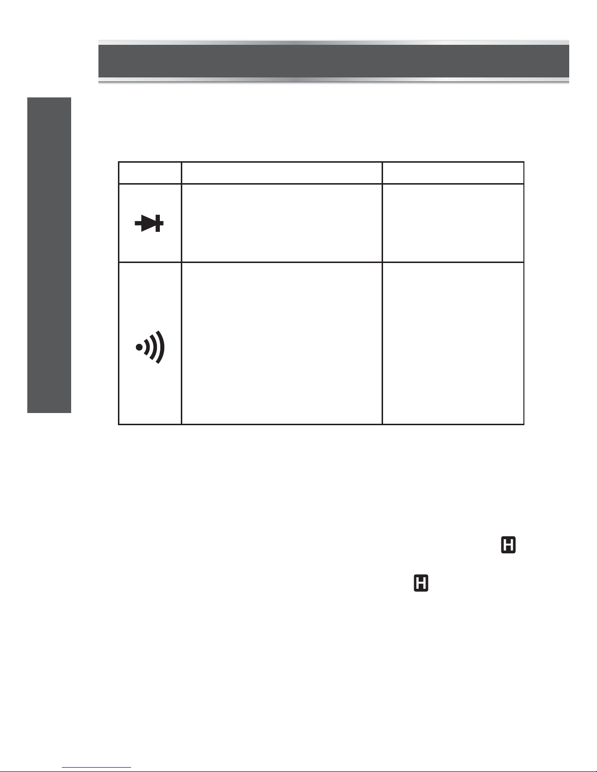
Alternating current
Direct current
Both direct and alternating current
Caution, risk of danger. Refer to the operating manual before
use.
Caution, risk of electric shock.
Earth (ground) terminal
Fuse
Conforms to European Union directives
The equipment is protected throughout by double insulation or
reinforced insulation.
CAUTION
ELECTRICAL SYMBOLS
model no. 052-0055-6 | contact us 1-800-689-9928
5
CAUTION
Page 7
This meter is a compact 3 1/2-digit digital multimeter designed to
measure DC and AC voltage, DC and AC current, resistance, continuity,
diode, battery and temperature. In addition, non-contact AC voltage
detection, live AC wire detection and illumination functions are also
provided. It features polarity indication, data hold, full-range overload
protection, and more. It is easy to operate and is a very useful test
tool.
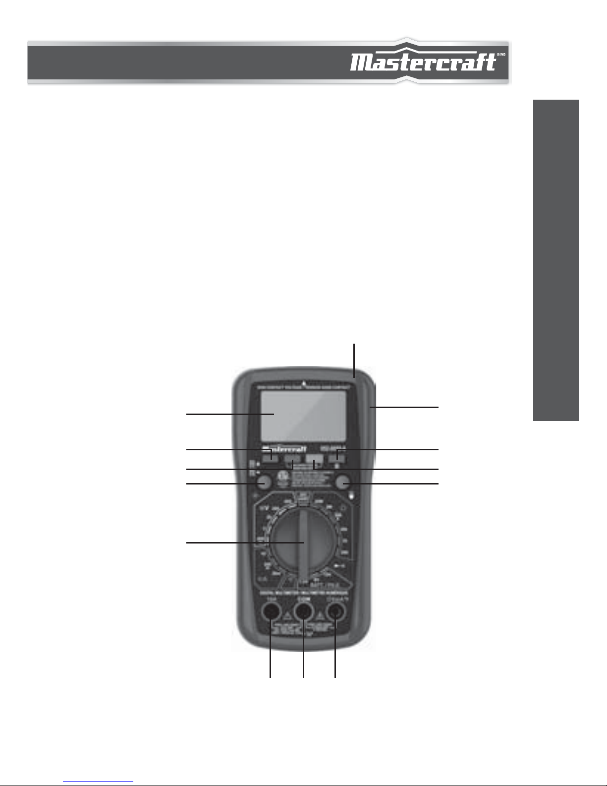
FRONT PANEL
INTRODUCTION
2
3
4
5
678
9
10
11
12
13
1
6
INTRODUCTION
Page 8

1.
2.
3.
4.
5.
6.
7.
8.
9.
10.
Display
3 1/2-digit LCD, with a max. reading of 1999.
"AC/DC" Button
Used to switch between DC and AC functions.
AC Voltage Detection Button
Backlight Button
Press this button to turn on or off the backlight. The backlight
will turn off automatically about 30 secs after it is turned on.
Function/Range Switch
Used to select desired function or range as well as to turn on or
off the meter. To preserve battery life, set the function/range
switch in the "OFF" position when the meter is not in use.
"10A" Terminal
Plug-in connector for the red test lead for current (200 mA
–
10 A)
measurements.
"COM" Terminal
This terminal is a plug-in connector for the black test lead. It is
also a plug-in connector for the negative (-) plug of a K type
thermocouple for temperature measurements.
"VmAºF" Terminal
This terminal is a plug-in connector for the red test lead for all
measurements except temperature measurements and the
current measurements ≥ 200 mA.
It is also a plug-in connector for the positive (+) plug of a K type
thermocouple for temperature measurements.
Illumination Button
Press and hold down this button to turn on the illumination
lamp. To turn off the illumination lamp, just release this button.
AC Voltage Detection Indicator
model no. 052-0055-6 | contact us 1-800-689-9928
7
INTRODUCTION
Page 9

GENERAL SPECIFICATIONS
SPECIFICATIONS
11.
12.
13.
"H" Button
Used to enter/exit Data Hold mode.
Holster
Illumination Lamp
Display: 3 1/2-digit LCD, with a max. reading of 1999
Negative Polarity Indication:
Negative sign " - " shown on the display automatically
Sampling Rate: About 2
–
3 times/sec
IP Degree: IP20
Battery: 9 V battery, 6F22 or equivalent, 1 pieces
Low Battery Indication: " " shown on the display
Operating Environment: Temperature: 32 to 104ºF (0 to 40°C)
Relative Humidity: < 75%
Storage Environment: Temperature: 14 to 122ºF (-10 to 50ºC)
Relative Humidity: < 85%
Size: 6 11/16 x 3 3/8 x 1 9/16" (170 x 86 x 40 mm)
Weight: About 10 1/4 oz (291 g) (including battery)
Readings are accurate for a period of one year after calibration at 64
to 82ºF (18 to 28ºC), with relative humidity < 75%.
Accuracy specifications take the form of:
±([% of Reading] + [number of Least Significant Digits])
8
TECHNICAL SPECIFICATIONS
Page 10
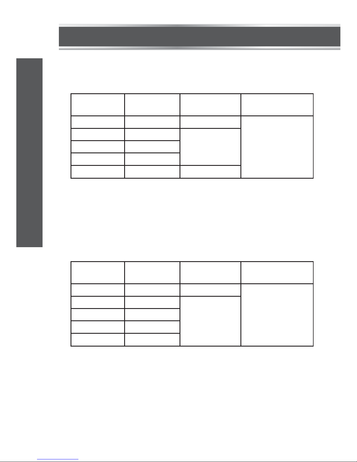
DC VOLTAGE
Input Impedance: 10 MΩ
Max. Allowable Input Voltage: 300 V DC
RANGE
200 mV 100 V ±(0.5% + 5)
±(1.0% + 5)
±(0.8% + 5)
"OL" shown
on the display
1 mV
10 mV
100 mV
1 V
2 V
20 V
200 V
300 V
RESOLUTION ACCURACY
OVERRANGE
INDICATION
AC VOLTAGE
Frequency Range: 40 – 400 Hz
Response: Average, calibrated in RMS of sine wave
Max. Allowable Input voltage: 300 V AC RMS
RANGE
200 mV 100 V ±(1.0% + 5)
±(1.2% + 5)
"OL" shown
on the display
1 mV
10 mV
100 mV
1 V
2 V
20 V
200 V
300 V
RESOLUTION ACCURACY
OVERRANGE
INDICATION
model no. 052-0055-6 | contact us 1-800-689-9928
9
TECHNICAL SPECIFICATIONS
Page 11
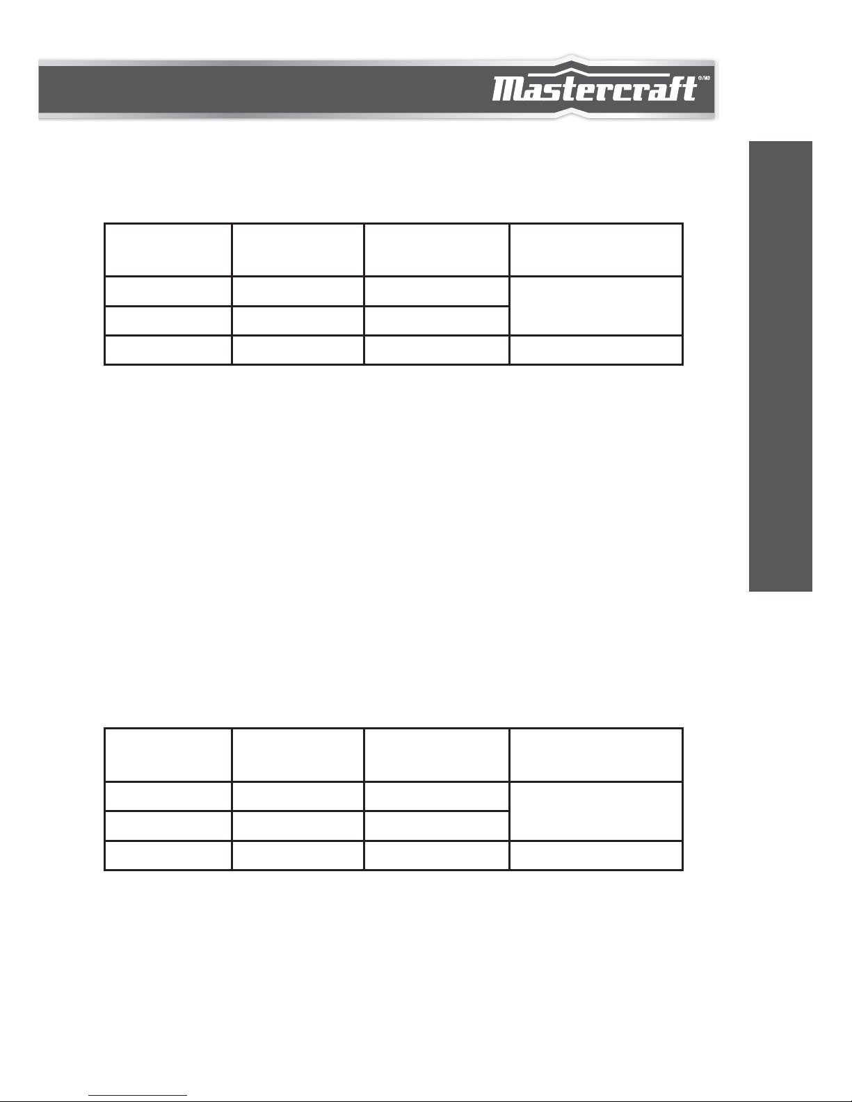
AC CURRENT
RANGE
20 mA 10 A ±(1.3% + 5)
±(3.0% + 5)
±(1.8% + 5)
"OL" shown
on the display
——— [ 1 ]
100 A
10 mA
200 mA
10 A
RESOLUTION ACCURACY
OVERRANGE
INDICATION
[ 1 ]
DC CURRENT
Overload Protection:
250 mA/300 V FAST Fuse (for "ΩVmA°F" terminal inputs)
10 A/300 V FAST Fuse (for "10A" terminal inputs)
Max. Allowable Input Current: 10 A
(For inputs > 2 A: measurement duration < 10 secs, and interval >
15 minutes)
If the current being measured is > 10 A, the display may show
the value of the current; but the measurement is dangerous.
RANGE
20 mA 10 A ±(1.0% + 5)
±(2.0% + 5)
±(1.5% + 5)
"OL" shown
on the display
——— [ 1 ]
100 A
10 mA
200 mA
10 A
RESOLUTION ACCURACY
OVERRANGE
INDICATION
10
TECHNICAL SPECIFICATIONS
Page 12

[ 1 ]
Overload Protection:
250 mA/300 V FAST Fuse (for "ΩVmA°F" terminal inputs)
10 A/300V FAST Fuse (for "10A" terminal inputs)
Max. Allowable Input Current: 10A
(For inputs > 2 A: measurement duration < 10 secs, and interval >
15 minutes)
Frequency Range: 40 – 400 Hz
Response: Average, calibrated in RMS of sine wave
Max. Open Circuit Voltage: About 2.8 V
If the current being measured is > 10 A, the display may show
the value of the current; but the measurement is dangerous.
RESISTANCE
RANGE
200 Ω 0.1 Ω
±(1.2% + 5)
±(1.5% + 7)
"OL" shown
on the display
1 Ω
10 Ω
100 Ω
1 kΩ
10 kΩ
2 kΩ
20 kΩ
200 kΩ
2 MΩ
20 MΩ
RESOLUTION ACCURACY
OVERRANGE
INDICATION
model no. 052-0055-6 | contact us 1-800-689-9928
11
TECHNICAL SPECIFICATIONS
Page 13
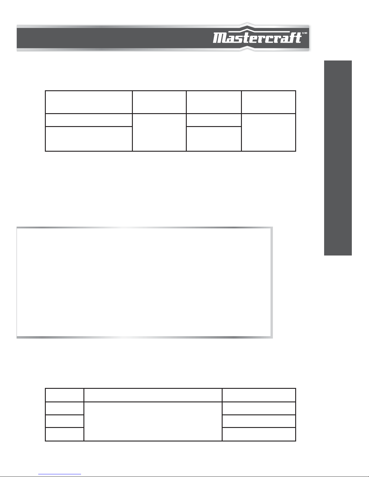
TEMPERATURE
[ 1 ] If the temperature being measured is out of the range of 32 to
1832ºF (0 to 1000ºC) the display may show a reading, but the
measurement error may be large or the thermocouple may be
damaged.
1.
2.
3.
Use a K type thermocouple.
Accuracy does not include error of the thermocouple
probe.
Accuracy specification assumes ambient temperature
is stable to ±1.8ºF (1ºC). For ambient temperature
changes of ±9ºF (5ºC), rated accuracy applies after 1
hour.
Note:
RANGE
32 to 752ºF (0 to 385ºC)
1ºF (0.6ºC)
±(1.0% + 5)
±(2.5% + 10)
——— [ 1 ]
752 to 1832ºF (385 to
1000ºC)
RESOLUTION ACCURACY
OVERRANGE
INDICATION
BATTERY TEST
RANGE
1.5 V about 20 mA
about 5 mA
about 4 mA
9 V
12 V
DESCRIPTION TEST CURRENT
The working voltage of the battery will
be shown on the display so that the
quality of the battery can be judged.
12
TECHNICAL SPECIFICATIONS
Page 14
DIODE AND CONTINUITY TEST
OPERATING INSTRUCTIONS
DATA HOLD MODE
Press the "H" button to hold the present reading on the display, " "
will appear on the display as an indication.
To exit Data Hold mode, press the button again. " " disappears.
RANGE DESCRIPTION TEST CURRENT
The approx. forward voltage drop
of the diode will be displayed.
The built-in buzzer will sound if
the resistance is less than
about 20 Ω.
The buzzer may or may not
sound if the resistance is
between 20 Ω and 100 Ω.
The buzzer will not sound if the
resistance is more than 100 Ω.
Open Circuit Voltage:
about 2.8 V
Test Current:
about 1 mA
Open Circuit Voltage:
about 2.8 V
model no. 052-0055-6 | contact us 1-800-689-9928
13
TECHNICAL SPECIFICATIONS
Page 15

MEASURING DC OR AC VOLTAGE
MEASURING DC OR AC CURRENT
1.
2.
3.
4.
5.
Connect the black test lead to the "COM" terminal and the red
test lead to the "ΩVmA°F" terminal.
Set the range switch to desired V range position. If the
magnitude of the voltage to be measured is not known
beforehand, set the range switch to the highest range first and
then reduce it range by range until satisfactory resolution is obtained.
Select DC or AC voltage measurement with the "AC/DC" button
according to the marks beside this button.
Connect the test leads across the source or circuit to be tested.
Read the reading on the display. For DC voltage measurements,
the polarity of the red test lead connection will be indicated as well.
1.
2.
3.
4.
5.
6.
Connect the black test lead to the "COM" terminal. Connect the
red test lead to the "ΩVmA°F" terminal if the current to be
measured is less than 200 mA. If the current is between 200 mA
and 10 A, connect the red test lead to the "10A" terminal instead.
Set the range switch to desired A range position.
Select DC or AC current measurement with the "AC/DC" button
according to the marks beside this button.
Turn off power to the circuit to be tested. Then discharge all
high-voltage capacitors.
Break the circuit path to be tested, then connect the test leads
in series with the circuit.
Turn on power to the circuit, then read the reading on the display.
For DC current measurements, the polarity of the red test lead
connection will be indicated as well.
14
OPERATING INSTRUCTIONS
Page 16

MEASURING RESISTANCE
CONTINUITY TEST
1.
2.
3.
4.
Connect the black test lead to the "COM" terminal and the red
test lead to the "ΩVmA°F" terminal.
Set the range switch to desired Ω range position.
Connect the test leads across the object to be tested.
Read the reading on the display.
1.
2.
3.
For measurements > 1 MΩ, the meter may take a few
seconds to stabilize reading. This is normal for high
resistance measurements.
When the input is not connected, i.e. at open circuit, "OL"
will be displayed as an overrange indication.
Before test, disconnect all power to the circuit to be tested
and discharge all capacitors thoroughly.
1.
2.
3.
4.
Connect the black test lead to the "COM" terminal and the red
test lead to the "ΩVmA°F" terminal.
Set the range switch to position.
Connect the test leads across the circuit to be tested.
If the resistance is less than about 20 Ω, the built-in buzzer will sound.
Note:
If the magnitude of the current to be measured is not known
beforehand, set the range switch to the highest range first and
then reduce it range by range until satisfactory resolution is
obtained.
Note:
model no. 052-0055-6 | contact us 1-800-689-9928
15
OPERATING INSTRUCTIONS
Page 17

Before test, disconnect all power to the circuit to be
tested and discharge all capacitors thoroughly.
Note:
Before test, disconnect all power to the circuit to be
tested and discharge all capacitors thoroughly.
Note:
DIODE TEST
1.
2.
3.
4.
Connect the black test lead to the "COM" terminal and the red
test lead to the "ΩVmA°F" terminal.
(Note: The polarity of the red lead is positive " + ")
Set the range switch to position.
Connect the red test lead to the anode of the diode to be tested
and the black test lead to the cathode of the diode.
The display will show the approximate forward voltage drop of
the diode. If the connection is reversed, "OL" will be shown on
the display.
BATTERY TEST
1.
2.
3.
4.
Connect the black test lead to the "COM" terminal and the red
test lead to the "ΩVmA°F" terminal.
According to the rated voltage of the battery to be tested, set the
range switch to the corresponding BATT. range position.
Connect the test leads to the two terminals of the battery to be tested.
The display shows the working voltage of this battery.
OPERATING INSTRUCTIONS
16
Page 18

MEASURING TEMPERATURE
1.
2.
3.
4.
Connect the negative ( - ) plug of the K type thermocouple to the
"COM" terminal and the positive ( + ) plug of the K type thermocouple to the "ΩVmA°F" terminal .
Set the range switch to the °F position.
Carefully touch the sensing end of the thermocouple to the
object to be tested.
Wait a while; read the reading on the display.
Note
To avoid possible damage to the meter or other equipment,
remember that while the meter is rated for 32 to 1832ºF (0 to
1000ºC), the K type thermocouple provided with the meter is
rated to 482°F (250°C). For temperatures out of that range, use
a higher rated thermocouple.
The K type thermocouple provided with the meter is not
professional and should only be used for non-critical measurements. For accurate measurements, use a professional
thermocouple.
model no. 052-0055-6 | contact us 1-800-689-9928
17
OPERATING INSTRUCTIONS
Page 19

1.
2.
3.
4.
5.
To avoid electric shock, do not touch any naked conductor with hand or skin.
Because of the meter's detection limit, a line (or conductor) under test may be live even if the buzzer does not
sound and the AC Voltage Detection Indicator does not
light.
Before use, verify the meter's operation by detecting a
known AC voltage.
When you just press and hold down the AC Voltage
Detection Button, the buzzer may sound two beeps and
the AC Voltage Detection Indicator may flash twice. This is
normal and doesn't matter.
Don't use the meter in an environment with an intense
electromagnetic field.
Connect the plug of a test lead to an input terminal of the meter, and
connect the probe tip of this test lead to the line's conductor to be
tested. Press and hold down the AC Voltage Detection Button. When
the meter detects AC voltage, the built-in buzzer will sound
discontinuously and the AC Voltage Detection Indicator will flash.
Note:
NON-CONTACT AC VOLTAGE DETECTION
LIVE AC WIRE DETECTION
Press and hold down the AC Voltage Detection Button and move the
top of the meter close to the object to be tested. When the meter
detects AC voltage, the built-in buzzer will sound discontinuously and
the AC Voltage Detection Indicator will flash.
18
OPERATING INSTRUCTIONS
Page 20

1.
2.
3.
4.
5.
To avoid electric shock, do not touch any naked conductor
with hand or skin.
Because of the meter's detection limit, a line (or conductor)
under test may be live even if the buzzer does not sound
and the AC Voltage Detection Indicator does not light.
Before use, verify the meter's operation by detecting a
known live AC wire (or conductor).
When you just press and hold down the AC Voltage
Detection Button, the buzzer may sound two beeps and the
AC Voltage Detection Indicator may flash twice. This is
normal and doesn't matter.
Don't use the meter in an environment with an intense
electromagnetic field.
Note:
WARNING
Except replacing fuse and battery, never attempt to repair or service
the meter unless you are qualified to do so and have the relevant
calibration, performance test, and service instructions.
Store the meter in a dry place when not in use. Don't store it in an
environment with an intense electromagnetic field.
MAINTENANCE
model no. 052-0055-6 | contact us 1-800-689-9928
19
OPERATING INSTRUCTIONS
Page 21

1.
2.
3.
4.
Set the range switch to OFF position and remove all test leads
from the meter.
Shake out any dirt which may exist in the terminals.
Soak a new swab with alcohol.
Work the swab around in each terminal. If the meter fails, check
and replace (as needed) the battery and fuses, and/or review
this manual to verify proper use of the meter.
Warning
To avoid false readings, which could lead to possible electric
shock or personal injury, replace the battery as soon as the low
battery indicator ( ) appears.
To prevent damage or injury, use only replacement fuses specified.
Before opening the battery cover or the case , turn off the meter
and remove the test leads.
Battery and Fuse Replacement
GENERAL MAINTENANCE
Periodically wipe the case with damp cloth and a little mild detergent.
Do not use abrasives or solvents.
Dirt or moisture in the terminals can affect readings. Clean the
terminals as follows:
20
MAINTENANCE
Page 22

F1:
F2:
250 mA/300 V fuse, Fast action, ø5×20 mm
10 A/300 V fuse, Fast action, ø5×20 mm
When the symbol " " appears on the display, the battery is low
and must be replaced immediately. To replace the battery, remove
the holster from the meter. Then remove the screw on the battery
cover and remove the battery cover. Replace the exhausted battery
with a new one of the same type, make sure that the polarity connections are correct. Reinstall the battery cover, the screw and the holster.
To replace the fuse, remove the holster from the meter. Remove the
screws on the back cover, open the back cover and move it aside
gently. Replace the damaged fuse with a new one of the same
ratings. Reinstall the back cover, the screws and the holster properly.
This meter uses two fuses:
Manual: 1 piece
Test lead: 1 pair
K Type Thermocouple: 1 piece
ACCESSORIES
model no. 052-0055-6 | contact us 1-800-689-9928
21
MAINTENANCE
Page 23

1.
2.
3.
This manual is subject to change without notice.
Our company will not take responsibility for any
loss.
The contents of this manual can not be used as the
reason to use the meter for any special application.
NOTE:
DISPOSAL OF THIS ARTICLE
Dear Customer,
If you at some point intend to dispose of this article,
then please keep in mind that many of its
components consist of valuable materials, which
can be recycled.
Please do not dispose of it in the garbage bin, but
check with your local council for recycling facilities
in your area.
WARRANTY
22
This Mastercraft product carries a one-year warranty against defects
in workmanship and materials. This product is not guaranteed
against wear, breakage or misuse.
WARRANTY
Page 24

Page 25

1.
2.
3.
Ce guide d'utilisation peut être modifié à tout moment sans
préavis.
Notre société ne sera pas tenue aux autres responsabilités
en cas de perte.
Le contenu de ce guide ne peut être appliqué pour utiliser
le multimètre de toute autre manière que ce soit.
REMARQUE
ÉLIMINATION DU PRODUIT
Chers clients,
Si vous avez l'intention à un moment donné de jeter
cet article, alors veuillez garder à l'esprit qu'un bon
nombre de ses composants sont constitués de
matériaux précieux, qui peuvent être recyclés.
Veuillez ne pas jeter ce produit à la poubelle.
Informez-vous plutôt auprès des organismes locaux
pour connaître l'emplacement des centres de
recyclage dans votre région.
N° de modèle : 052-0055-6 | Communiquez avec nous au 1 800 689-9928
23
GARANTIE
GARANTIE
Cet article Mastercraft comprend une garantie de un (1) an contre les
défauts de fabrication et de matériau(x). Exclusion : usure ou bris
causés par un usage abusif ou inapproprié.
Page 26

F1 :
F2 :
250 mA/300 V, action rapide, Ø5 x 20 mm
10 A/300 V, action rapide, Ø5 x 20 mm
Lorsque le symbole « » s'affiche à l'écran, cela signifie que la pile
est faible et doit être remplacée immédiatement. Pour remplacer la
pile, retirez le multimètre de son étui. Retirez ensuite la vis sur le
couvercle arrière, puis retirez le couvercle arrière. Remplacez la pile
usagée par une pile de même type, en veillant à faire correspondre
les polarités. Replacez le couvercle de la pile, la vis et l'étui.
Pour remplacer le fusible, retirez le multimètre de son étui. Retirez
les vis du couvercle arrière et retirez délicatement le couvercle
arrière. Remplacez le fusible endommagé par un nouveau fusible
similaire. Replacez le couvercle arrière, les vis et l'étui.
Ce multimètre fonctionne avec deux fusibles :
Guide d'utilisation : 1
Fils d'essai : 2
Thermocouple de type K : 1
ACCESSOIRES
ENTRETIEN
22
Page 27

1.
2.
3.
4.
Mettez la molette en position d'arrêt et retirez les fils d'essai du
multimètre.
Évacuez toute saleté qui pourrait s'être logée dans les bornes.
Imbibez d'alcool un coton propre.
Passez le coton autour de chaque borne. Si le multimètre ne
semble pas fonctionner correctement, vérifiez et remplacez (au
besoin) la pile ou les fusibles, ou lisez ce guide d'utilisation pour
vérifier que vous l'utilisez correctement.
Avertissement
Pour éviter les erreurs de lecture pouvant mener à d'éventuels
chocs électriques ou blessures, remplacez la pile dès que
l'indicateur de pile faible ( ) apparaît.
Pour éviter les dommages ou les blessures, utilisez uniquement
les fusibles de rechange conseillés.
Avant d'ouvrir le couvercle de la pile ou le boîtier, éteignez le
multimètre et retirez les fils d'essai.
ENTRETIEN GÉNÉRAL
Remplacement de la pile et des fusibles
Essuyez le boîtier périodiquement avec un chiffon humide et un peu
de nettoyant doux. N'utilisez pas d'abrasifs ou de solvants.
La saleté ou l'humidité dans les bornes peuvent affecter la lecture
des résultats. Nettoyez les bornes de la manière suivante :
N° de modèle : 052-0055-6 | Communiquez avec nous au 1 800 689-9928
21
ENTRETIEN
Page 28

1.
2.
3.
4.
5.
Pour éviter tout choc électrique, ne touchez aucun fil
conducteur nu avec la main ou la peau.
En raison des limites de détection du multimètre, il se peut
qu'une ligne (ou un conducteur) testée soit chargée, même
si l'alarme ne sonne pas et le témoin de détection de
tension CA ne s'allume pas.
Avant l'utilisation, vérifiez le bon fonctionnement du
multimètre en détectant un fil (ou un conducteur) sous
tension CA connue.
Lorsque vous maintenez le bouton de détection de tension
CA, l'alarme peut retentir deux fois et le témoin de détection
de tension CA peut clignoter deux fois. Il s'agit d'un compor-
tement normal qui n'a aucune incidence.
N'utilisez pas le multimètre dans un environnement où le
champ électromagnétique est fort.
Remarque
AVERISSEMENT
À l'exception du remplacement des fusibles et de la pile, n'essayez
pas de réparer le multimètre par vous-même, à moins que vous
soyez qualifié pour le faire et que vous ayez les instructions relatives
à la calibration, au test de fonctionnement et à la réparation.
Rangez le multimètre dans un endroit sec lorsque vous ne l'utilisez
pas. Ne rangez pas le multimètre dans un environnement où le
champ électromagnétique est fort.
ENTRETIEN
20
CONSIGNES D’UTILISATION
Page 29

1.
2.
3.
4.
5.
Pour éviter tout choc électrique, ne touchez aucun fil
conducteur nu avec la main ou la peau.
En raison des limites de détection du multimètre, il se peut
qu'une ligne (ou un conducteur) testée soit chargée, même
si l'alarme ne sonne pas et le témoin de détection de
tension CA ne s'allume pas.
Avant d'utiliser le multimètre, vérifiez qu'il fonctionne en
détectant une tension CA connue.
Lorsque vous maintenez le bouton de détection de tension
CA, l'alarme peut retentir deux fois et le témoin de
détection de tension CA peut clignoter deux fois. Il s'agit
d'un comportement normal qui n'a aucune incidence.
N'utilisez pas le multimètre dans un environnement où le
champ électromagnétique est fort.
Branchez le fil d'essai dans une borne d'entrée du multimètre et
branchez la sonde de ce même fil d'essai dans le conducteur de la
ligne à tester. Maintenez le bouton de détection de tension CA
enfoncé. Lorsque le multimètre détecte une tension CA, l'alarme
intégrée retentira de façon discontinue et le témoin de détection de
tension CA clignotera.
Remarque :
DÉTECTION DE TENSION CA SANS CONTACT
DÉTECTION DE CÂBLES CA SOUS TENSION
Maintenez le bouton de détection de tension CA et placez le dessus
du multimètre près de l'objet à vérifier. Lorsque le multimètre
détecte une tension CA, l'alarme intégrée retentira de façon
discontinue et le témoin de détection de tension CA clignotera.
N° de modèle : 052-0055-6 | Communiquez avec nous au 1 800 689-9928
19
CONSIGNES D’UTILISATION
Page 30

MESURE DE LA TEMPÉRATURE
1.
2.
3.
4.
Branchez la fiche négative « - » du thermocouple de type K dans
la borne « COM » et la fiche positive « + » dans la borne
« VmA°F ».
Mettez la molette de sélection sur le calibre « °F ».
Posez délicatement le côté sensible du thermocouple sur l'objet
à vérifier.
Attendez un peu avant de lire le résultat qui s'affiche à l'écran.
Remarque
Afin d'éviter d'endommager le multimètre ou tout autre
équipement, n'oubliez pas que le multimètre est capable de
supporter des températures allant de 0 à 1 000 °C (de 32 à
1832 °F), mais que le thermocouple de type K fourni est
capable de supporter des températures allant jusqu'à 250 °C
(482 °F). Pour mesurer des températures en dehors de cette
gamme, utilisez un thermocouple plus puissant.
Le thermocouple de type K fourni avec ce multimètre n'est pas
destiné à un usage professionnel et peut uniquement être
utilisé pour des mesures non critiques. Pour des mesures
précises, utilisez un thermocouple professionnel.
18
CONSIGNES D’UTILISATION
Page 31

Remarque :
Avant de procéder à la vérification, coupez le circuit électrique
et déchargez soigneusement tous les condensateurs.
Remarque :
Avant de procéder à la vérification, coupez le circuit électrique
et déchargez soigneusement tous les condensateurs.
TEST DE DIODE
1.
2.
3.
4.
Branchez le fil d'essai noir dans la borne « COM » et le fil d'essai
rouge dans la borne « VmA°F ». (Remarque : La polarité du
fil rouge est positive « + »).
Mettez la molette de sélection en position « ».
Branchez le fil d'essai rouge dans l'anode de la diode à vérifier
et le fil d'essai noir dans la cathode de la diode.
L'écran affichera la chute de tension directe approximative de la
diode. Si le branchement est inversé, « OL » s'affichera sur
l'écran.
VÉRIFICATION DE LA PILE
1.
2.
3.
4.
Branchez le fil d'essai noir dans la borne « COM » et le fil d'essai
rouge dans la borne « VmA°F ».
En fonction de la tension nominale de la pile à tester, placez la
molette de sélection sur la position BATT appropriée.
Branchez les fils d'essai sur les deux bornes de la pile à tester.
Le résultat affiché indique la tension de la pile.
N° de modèle : 052-0055-6 | Communiquez avec nous au 1 800 689-9928
17
CONSIGNES D’UTILISATION
Page 32

MESURE DE LA RÉSISTANCE
TEST DE CONTINUITÉ
1.
2.
3.
4.
Branchez le fil d'essai noir dans la borne « COM » et le fil d'essai
rouge dans la borne « VmA°F ».
Tournez la molette de sélection sur le calibre désiré.
Branchez les fils d'essai sur l'objet à tester.
Lisez le chiffre affiché sur l'écran.
1.
2.
3.
Pour les mesures supérieures à 1 M, il se peut que le
multimètre ait besoin de quelques secondes pour se stabiliser.
Ce comportement est normal lorsque des résistances élevées
sont mesurées.
Lorsque l'entrée n'est pas branchée (p. ex., circuit ouvert),
« OL » s'affichera pour indiquer un dépassement.
Avant de procéder à la vérification, coupez le circuit électrique
et déchargez soigneusement tous les condensateurs.
1.
2.
3.
4.
Branchez le fil d'essai noir dans la borne « COM » et le fil d'essai
rouge dans la borne « VmA°F ».
Mettez la molette de sélection en position « ».
Branchez les fils d'essai sur le circuit à tester.
Si la résistance est inférieure à environ 20 , l'alarme intégrée
retentira.
Remarque :
Si l'amplitude du courant n'est pas connue au préalable, placez
la molette sur le calibre le plus élevé, puis réduisez-le petit à
petit jusqu'à obtenir la résolution voulue.
Remarque :
CONSIGNES D’UTILISATION
16
Page 33

MESURE DE LA TENSION CC OU CA
MESURE DU COURANT CC OU CA
1.
2.
3.
4.
5.
Branchez le fil d'essai noir dans la borne « COM » et le fil d'essai
rouge dans la borne « VmA°F ».
Tournez la molette de sélection sur la position V désirée. Si
l'amplitude de la tension n'est pas connue au préalable, placez
la molette sur le calibre le plus élevé, puis réduisez-le petit à
petit jusqu'à obtenir la résolution voulue.
Sélectionnez la mesure de tension CC ou CA avec le bouton
« CA/CC » en fonction des symboles situés à côté de ce bouton.
Branchez les fils d'essai dans la source ou le circuit à vérifier.
Lisez le chiffre affiché sur l'écran. Pour les mesures de tension
CC, la polarité du fil d'essai rouge sera également indiquée.
1.
2.
3.
4.
5.
6.
Branchez le fil d'essai noir à la borne « COM ». Branchez le fil
d'essai rouge dans la borne « VmA°F » si le courant à mesurer
est inférieur à 200 mA. Si le courant se situe entre 200 mA et
10 A, branchez le fil d'essai rouge dans la borne « 10A ».
Tournez la molette de sélection sur la position A désirée.
Sélectionnez la mesure de courant CC ou CA avec le bouton
« CA/CC » en fonction des symboles situés à côté de ce bouton.
Coupez l'alimentation du circuit à vérifier. Déchargez ensuite
tous les condensateurs à haute tension.
Interrompez le circuit à vérifier et branchez les fils d'essai en
série avec le circuit.
Mettez en marche l'alimentation du circuit, puis lisez le résultat
sur l'écran. Pour les mesures de courant CC, la polarité du fil
d'essai rouge sera également indiquée.
N° de modèle : 052-0055-6 | Communiquez avec nous au 1 800 689-9928
15
CONSIGNES D’UTILISATION
Page 34

TEST DE DIODE ET DE CONTINUITÉ
CONSIGNES D’UTILISATION
MODE MÉMOIRE
Appuyez sur le bouton « H » pour laisser le chiffre affiché sur l'écran.
« » s'affichera. Pour quitter le mode Mémoire, appuyez de nouveau
sur le bouton. « » disparaîtra alors.
CALIBRE DESCRIPTION COURANT TESTÉ
La chute de tension directe
approximative de la diode sera
affichée.
L'alarme intégrée retentira si la
résistance est inférieure à environ
20 .
L'alarme retentira ou non si la
résistance se situe entre 20 et 100
.
L'alarme ne retentira pas si la
résistance est supérieure à 100
Tension à circuit ouvert :
environ 2,8 V
Courant testé : environ
1 mA
Tension à circuit ouvert :
environ 2,8 V
14
FICHE TECHNIQUE
Page 35

TEMPÉRATURE
[ 1 ] Si la température mesurée se situe en dehors de la gamme
0-1 000 °C (32-1 832 °F), le résultat affiché pourrait être erroné
et le thermocouple endommagé.
1.
2.
3.
Utilisez un thermocouple de type K.
Le système de précision ne prend pas en compte les
erreurs de la sonde du thermocouple.
Le système de précision suppose que la température
ambiante est stable à ± 1 °C (1,8 °F).
. En cas de changement de température de ±5 °C (9 °F), la
précision nominale s'applique après 1 heure.
Remarque :
De 0 à 385 °C
(de 32 à 752 °F)
0,6 °C (1 °F)
±(1,0 % + 5)
±(2,5 % + 10)
De 385 à 1 000 °C
(de 752 à 1 832 °F)
VÉRIFICATION DE LA PILE
CALIBRE
1,5 V Environ 20 mA
Environ 5 mA
Environ 4 mA
9 V
12 V
DESCRIPTION COURANT TESTÉ
La tension de la pile s'affichera sur
l'écran afin que la qualité de la pile soit
évaluée.
CALIBRE RÉSOLUTION PRÉCISION
TÉMOIN DE
DÉPASSEMENT
------ [1]
N° de modèle : 052-0055-6 | Communiquez avec nous au 1 800 689-9928
13
FICHE TECHNIQUE
Page 36

[ 1 ]
Protection contre la surcharge :
250 mA/300 V, action rapide (pour les mesures sur la borne
« VmA°F »)
10 A/300 V, action rapide (pour les mesures sur la borne « 10 A »)
Courant d'entrée maximal autorisé : 10 A
(Pour les mesures supérieures à 2 A : la durée de la mesure est
inférieure à 10 secondes et l'intervalle est supérieur à 15 minutes).
Gamme de fréquences : 40-400 Hz
Réponse: moyenne, calibrée en RMS d'onde sinusoïdale
Tension à circuit ouvert maximal : environ 2,8 V
Si le courant mesuré est supérieur à 10 A, cela présente un
danger, même si le résultat s'affiche.
RÉSISTANCE
200 Ω 0,1 Ω
±(1,2 % + 5)
±(1,5 % + 7)
1 Ω
10 Ω
100 Ω
1 kΩ
10 kΩ
2 kΩ
20 kΩ
200 kΩ
2 MΩ
20 MΩ
CALIBRE
« OL » s'affiche
sur l'écran
RÉSOLUTION PRÉCISION
TÉMOIN DE
DÉPASSEMENT
12
FICHE TECHNIQUE
Page 37

COURANT CC
COURANT CA
20 mA 10 A ±(1,3 % + 5)
±(3,0 % + 5)
±(1,8 % + 5)100 A
10 mA
200 mA
10 A
[ 1 ]
Protection contre la surcharge :
250 mA/300 V, action rapide (pour les mesures sur la borne
« VmA°F »).
10 A/300 V, action rapide (pour les mesures sur la borne « 10 A »).
Courant d'entrée maximal autorisé : 10 A
(Pour les mesures supérieures à 2A : la durée de la mesure est
inférieure à 10 secondes et l'intervalle est supérieur à 15 minutes).
Si le courant mesuré est supérieur à 10 A, cela présente un
danger, même si le résultat s'affiche.
20 mA 10 A ±(1,0 % + 5)
±(2,0 % + 5)
±(1,5 % + 5)
------ [1]
100 A
10 mA
200 mA
10 A
CALIBRE
« OL » s'affiche
sur l'écran
RÉSOLUTION PRÉCISION
TÉMOIN DE
DÉPASSEMENT
CALIBRE
« OL » s'affiche
sur l'écran
RÉSOLUTION PRÉCISION
TÉMOIN DE
DÉPASSEMENT
------ [1]
N° de modèle : 052-0055-6 | Communiquez avec nous au 1 800 689-9928
11
FICHE TECHNIQUE
Page 38

TENSION CC
Impédance d'entrée : 10 M
Tension d'entrée maximale autorisée : 300 V CC
CALIBRE
200 mV 100 V ±(0,5 % + 5)
±(1,0 % + 5)
±(0,8 % + 5)
« OL » s'affiche
sur l'écran
1 mV
10 mV
100 mV
1 V
2 V
20 V
200 V
300 V
RÉSOLUTION PRÉCISION
TÉMOIN DE
DÉPASSEMENT
TENSION CA
Gamme de fréquences : 40-400 Hz
Réponse : moyenne, calibrée en RMS d'onde sinusoïdale
Tension d'entrée maximale autorisée : 300 V CA RMS
CALIBRE
200 mV 100 V ±(1,0 % + 5)
±(1,2 % + 5)
« OL » s'affiche
sur l'écran
1 mV
10 mV
100 mV
1 V
2 V
20 V
200 V
300 V
RÉSOLUTION PRÉCISION
TÉMOIN DE
DÉPASSEMENT
FICHE TECHNIQUE
1010
Page 39

GÉNÉRALITÉS
FICHE TECHNIQUE
10.
11.
12.
13.
Témoin de détection de tension CA
Bouton « H »
Sert à ouvrir/quitter le mode de maintien des données à l'écran.
Étui
Lampe
Écran : Écran ACL 3 1/2 chiffres avec lecture jusqu'à 1 999 points
Témoin de polarité négative :
Le symbole « – » s'affiche automatiquement sur l'écran
Cadence d'échantillonnage : Environ 2 à 3 fois par seconde
Degré de l'IP : IP20
Pile : Pile de 9 V, 6F22 ou équivalent x 1
Témoin de pile faible : « » s'affiche sur l'écran
Environnement de fonctionnement :
Température : de 0 à 40 °C (de 32 à 104 °F)
Humidité relative : < 75 %.
Environnement de stockage :
Température : de - 10 à 50 °C (de 14 à 122 °F)
Humidité relative : < 85 %
Dimensions : 170 x 86 x 40 mm (6 11/16 x 3 3/8 x 1 9/16 po)
Poids : environ 291 g (10 1/4 oz) (pile incluse)
Les relevés sont précis pendant une période d'un an après un
étalonnage des températures de 18 à 28 °C (de 64 à 82 °F), avec une
humidité relative inférieure à 75 %.
Les caractéristiques d'exactitude prennent la forme suivante :
± ([% du relevé]+[Nombre de chiffres les moins
significatifs]).
N° de modèle : 052-0055-6 | Communiquez avec nous au 1 800 689-9928
9
FICHE TECHNIQUE
Page 40

1.
2.
3.
4.
5.
6.
7.
8.
9.
Écran
Écran ACL 3 1/2 chiffres avec lecture jusqu'à 1 999 points.
Bouton « CA/CC »
Sert à passer de la fonction CC à la fonction CA.
Bouton de détection de tension CA
Bouton de rétroéclairage
Appuyez sur ce bouton pour activer ou désactiver le
rétroéclairage. Le rétroéclairage s'éteindra automatiquement
environ 30 secondes après son activation.
Molette Fonction/Calibre
Sert à sélectionner la fonction et le calibre désirés, et à mettre
en marche/arrêter le multimètre. Pour préserver la pile, mettez
la molette Fonction/Calibre en position « OFF » lorsque vous
n'utilisez pas le multimètre.
Borne « 10 A »
Branchez le connecteur du fil d'essai rouge pour mesurer le
courant (200 mA-10 A).
Borne « COM »
Cette borne permet de brancher le fil d'essai noir. Elle permet
également de brancher le fil négatif (-) d'un thermocouple de
type K pour mesurer des températures.
Borne « VmAºF »
Cette borne permet de brancher le fil d'essai rouge pour
effectuer n'importe quelle mesure, à l'exception de la tempéra-
ture et du courant ≥ 200 mA.
Elle permet également de brancher le fil positif (+) d'un thermo-
couple de type K pour mesurer des températures.
Bouton d'éclairement
Maintenez ce bouton pour activer la lampe. Pour désactiver la
lampe, relâchez simplement ce bouton.
8
INTRODUCTION
Page 41

Cet appareil est un multimètre numérique compact avec afficheur
3 1/2 chiffres. Il s'utilise pour mesurer la tension CC/CA, le courant
CA/CC, la résistance, la continuité, les diodes, les piles et la tempéra-
ture. Il permet également de détecter une tension CA sans contact,
de détecter un fil CA sous tension et de mesurer l'éclairement. Il
dispose d'une indication de polarité, d'une mémoire, d'une
protection complète contre la surcharge et plus encore. Facile à
utiliser, ce multimètre est un outil de vérification très utile.
PANNEAU AVANT
INTRODUCTION
2
3
4
5
678
9
10
11
12
13
1
N° de modèle : 052-0055-6 | Communiquez avec nous au 1 800 689-9928
7
INTRODUCTION
Page 42

Courant alternatif
Courant continu
Courant continu et courant alternatif
Attention : Risque de danger. Reportez-vous au guide d'utilisa-
tion avant toute utilisation
Attention : Risque de choc électrique
Borne de terre
Fusible
Conforme aux directives de l'Union européenne
Cet appareil est protégé par une double isolation ou une
isolation renforcée
SYMBOLES ÉLECTRIQUES
6
ATTENTION
Page 43

Pour éviter d'endommager le multimètre ou l'équipement lors de la
vérification, suivez ces consignes :
ATTENTION
N° de modèle : 052-0055-6 | Communiquez avec nous au 1 800 689-9928
5
ATTENTION
●
●
●
●
Coupez le circuit électrique et déchargez soigneusement tous
les condensateurs avant de vérifier la résistance, une diode, la
continuité ou la température.
Utilisez les bornes, la fonction et le calibre appropriés pour vos
mesures.
Avant de mesurer du courant, vérifiez les fusibles du multimètre
et coupez le circuit électrique avant de brancher le multimètre
au circuit.
Avant de tourner la molette de sélection pour changer de
fonction, débranchez les fils d'essai du circuit en cours de
vérification.
Page 44

●
●
●
●
Pour éviter tout choc électrique, ne touchez aucun fil conducteur
nu avec la main ou la peau et ne vous tenez pas directement sur
le sol lorsque vous utilisez le multimètre.
N'utilisez pas le multimètre si vos mains, un fil d'essai ou
l'appareil sont mouillés.
Autre danger :
Lorsqu'une borne d'entrée est reliée à un potentiel dangereux, il
est à noter que ce potentiel peut parvenir à toutes les autres
bornes!
CAT III - La catégorie de mesure III concerne les mesures
effectuées en construction. Par exemple : mesures effectuées
sur des tableaux de distribution, des disjoncteurs, des câblages,
y compris les câbles, les barres omnibus, les boîtes de jonction,
les interrupteurs et les prises de courant sur une installation
fixe, ainsi que sur de l'équipement à usage industriel ou non, tel
que les moteurs fixes avec un branchement permanent à une
installation fixe. N'utilisez pas le multimètre pour effectuer des
mesures d'appareils de catégorie IV.
4
AVERTISSEMENT
Page 45

●
●
●
●
●
●
●
●
●
●
Avant de mesurer du courant, mettez le panneau électrique hors
service avant de brancher le multimètre au circuit. N'oubliez
pas de mettre le multimètre en série dans le circuit.
Lors de l'entretien de votre multimètre, utilisez uniquement des
pièces de rechange spécifiques.
Faites preuve de prudence lorsque vous travaillez avec des
intensités électriques supérieures à 30 V CA RMS, 42 V max. ou
60 V CC. De telles intensités présentent un risque de choc
électrique.
Lorsque vous utilisez les sondes, veillez à placer vos doigts
derrière les protège-doigts situés sur les sondes.
Branchez le fil d'essai de terre avant de brancher le fil d'essai
sous tension. Lorsque vous débranchez les fils d'essai,
commencez par retirer le fil d'essai sous tension.
Retirez les fils d'essai du multimètre avant d'ouvrir le couvercle
ou le compartiment de la pile.
Ne faites pas fonctionner le multimètre lorsque le couvercle de
la pile ou certaines parties de celui-ci sont retirés ou desserrés.
Pour éviter les erreurs de lecture pouvant mener à d'éventuels
chocs électriques ou blessures, remplacez la pile dès que
l'indicateur de pile faible ( ) apparaît.
N'utilisez pas ce multimètre d'une quelconque façon non
décrite dans ce guide, sans quoi le dispositif de sécurité intégré
pourrait être altéré.
Respectez les codes de sécurité locaux et nationaux. Des
équipements de protection doivent être utilisés pour prévenir
les blessures dues aux chocs et aux arcs électriques, lorsque
des conducteurs sous tension sont exposés.
N° de modèle : 052-0055-6 | Communiquez avec nous au 1 800 689-9928
3
AVERTISSEMENT
Page 46

CONSIGNES DE SÉCURITÉ
Ce multimètre a été conçu conformément à la norme CEI 61010 sur
les appareils de mesure électroniques; il fait partie de la catégorie de
mesure CAT III 300V et son degré de pollution est de 2.
AVERTISSEMENT
Pour éviter tout risque de choc électrique ou de blessure, suivez ces
consignes :
●
●
●
●
●
●
N'utilisez pas le multimètre s'il est endommagé. Avant d'utiliser
le multimètre, inspectez le boîtier. Prêtez une attention toute
particulière à l'isolation autour des connecteurs.
Inspectez les fils d'essai pour détecter un problème d'isolation
ou une exposition du métal. Vérifiez la continuité électrique des
fils d'essai. Remplacez les fils d'essai endommagés avant
d'utiliser le multimètre.
N'utilisez pas le multimètre s'il fonctionne de façon anormale. Il
se peut que le système de protection soit altéré. En cas de
doute, faites réviser votre multimètre.
Ne faites pas fonctionner le multimètre en présence de
poussière, de vapeurs ou de gaz explosifs.
Ne dépassez pas la tension nominale, indiquée sur le
multimètre, entre les bornes ou entre une borne et la terre.
Avant d'utiliser le multimètre, vérifiez qu'il fonctionne en
mesurant une tension connue.
2
AVERTISSEMENT
Page 47

Page 48

MANUAL
MULTIMÈTRE NUMÉRIQUE
GUIDE
D’UTILISATION
N° de modèle :
052-0055-6
Avant d'utiliser le produit, veuillez lire attentivement et
bien comprendre ce guide d'utilisation. Ce guide
contient des consignes de sécurité importantes ainsi
que des consignes relatives à l'utilisation et à l'entretien
du produit.
Conservez ce guide d'utilisation pour toute consultation
ultérieure. Si vous remettez ce produit à un tiers, ce
guide d'utilisation doit l'accompagner.
 Loading...