

Page 1
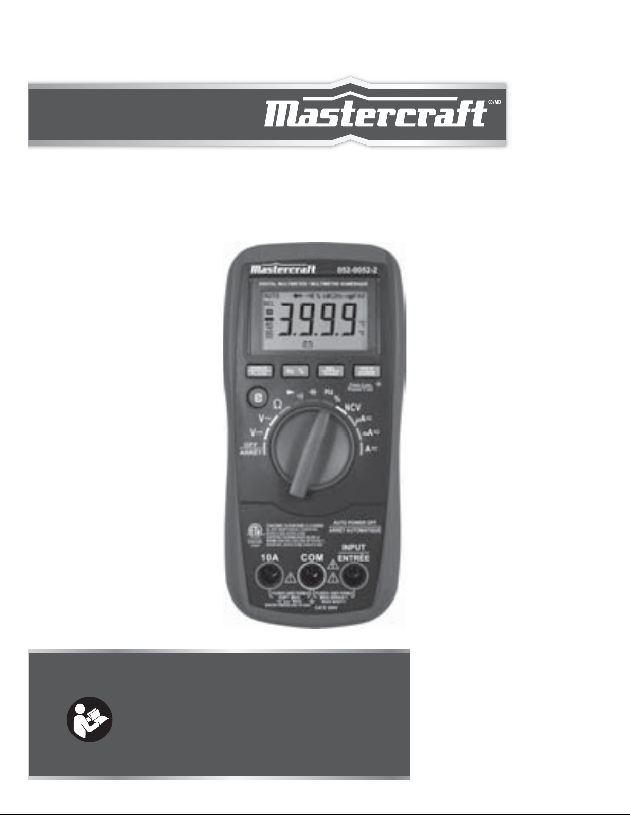
AUTO-RANGING
DIGITAL MULTIMETER
INSTRUCTION
MANUAL
model no. 052-0052-2
Read and understand this instruction manual thoroughly
before using the product. It contains important
information for your safety as well as operating and
maintenance advice.
Keep this instruction manual for future use. Should this
product be passed on to a third party, then this
instruction manual must be included.
Page 2

Page 3

SAFETY INFORMATION
This meter has been designed according to EC 61010 concerning
electronic measuring instruments with a measurement category
(CAT IV 600V) and pollution degree 2.
WARNING
To avoid possible electric shock or personal injury, follow these
guidelines:
●
●
●
●
●
●
●
Do not use the meter if it is damaged. Before you use the meter,
inspect the case. Pay particular attention to the insulation
surrounding the connectors.
Inspect the test leads for damaged insulation or exposed metal.
Check the test leads for continuity. Replace damaged test leads
before you use the meter.
Do not use the meter if it operates abnormally. Protection may
be impaired. When in doubt, have the meter serviced.
Do not operate the meter where explosive gas, vapour or dust is
present.
Do not apply more than the rated voltage, as marked on the
meter, between terminals or between any terminal and earth
ground.
Before use, verify the meter's operation by measuring a known
voltage.
When measuring current, turn off circuit power before connecting the meter in the circuit. Remember to place the meter in
series with the circuit.
2
WARNING
Page 4
●
●
●
●
●
●
●
●
●
●
●
●
●
●
When servicing the meter, use only specified replacement parts.
Use caution when working with voltage above 30 V AC RMS, 42
V peak, or 60 V DC. Such voltages pose a shock hazard.
When using the probes, keep your fingers behind the finger
guards on the probes.
When making connections, connect the common test lead
before you connect the live test lead. When you disconnect test
leads, disconnect the live test lead first.
Remove the test leads from the meter before you open the
battery cover or the case.
Do not operate the meter with the battery cover or portions of
the case removed or loosened.
To avoid false readings, which could lead to possible electric
shock or personal injury, replace the battery as soon as the low
battery indicator ( ) appears.
When in Relative mode ("REL" is displayed) or in Data Hold
mode (" " is displayed), caution must be used because
hazardous voltage may be present.
Do not use the meter in a manner not specified by this manual
or the safety features provided by the meter may be impaired.
Adhere to local and national safety codes. Individual protective
equipment must be used to prevent shock and arc blast injury
where hazardous live conductors are exposed.
To avoid electric shock, do not touch any naked conductor with
your hand or skin, and do not ground yourself.
Do not use the supplied test leads with other equipment.
Do not use the meter if your hand or the meter is wet.
When an input terminal is connected to dangerous live potential,
it is to be noted that this potential can occur at all other terminals!
model no. 052-0052-2 | contact us 1-800-689-9928
3
WARNING
Page 5

●
●
CAT IV - Measurement Category IV is for measurements performed
at the source of the low-voltage installation. Examples are
electricity meters and measurements on primary overcurrent
protection devices and ripple control units.
For measurements on main or within Measurement Category
Ⅲ/Ⅳcircuits, the attached test probes must be set in Measurement Category Ⅲ/Ⅳmode; otherwise, electric shock may
occur!
4
WARNING
Page 6

To avoid possible damage to the meter or to the equipment under
test, follow these guidelines:
●
●
●
●
●
Disconnect circuit power and discharge all capacitors thoroughly before measuring resistance, diode, capacitor, temperature
and continuity.
Use the proper terminals, function and range for your measurements.
Before measuring current, check the meter's fuses and turn off
the power to the circuit before connecting the meter to the circuit.
Before rotating the rotary switch to change functions, disconnect
test leads from the circuit under test.
The meter uses multiple anti-interference designs, but it may
stop working if the interference in the environment is too
intense. Turning on the meter again can solve this problem.
CAUTION
model no. 052-0052-2 | contact us 1-800-689-9928
5
CAUTION
Page 7

Model 052-0052-2 meter is a compact 3 3/4-digit digital multimeter
for measuring DC and AC voltage, DC and AC current, resistance,
continuity, diode, capacitance, frequency, duty cycle and non-contact
AC voltage detection function.
It features relative measurement, data hold, backlight, low battery
indication, overrange indication, automatic power-off, full-range
overload protection, autoranging and more. It is easy to operate and
is an ideal test tool.
Alternating current
Direct current
Both direct and alternating current
Caution, risk of danger. Refer to the operating manual before use.
Caution, risk of electric shock.
Earth (ground) terminal
Fuse
Conforms to European Union directives
The equipment is protected throughout by double insulation or
reinforced insulation.
INTRODUCTION
ELECTRICAL SYMBOLS
6
INTRODUCTION
Page 8
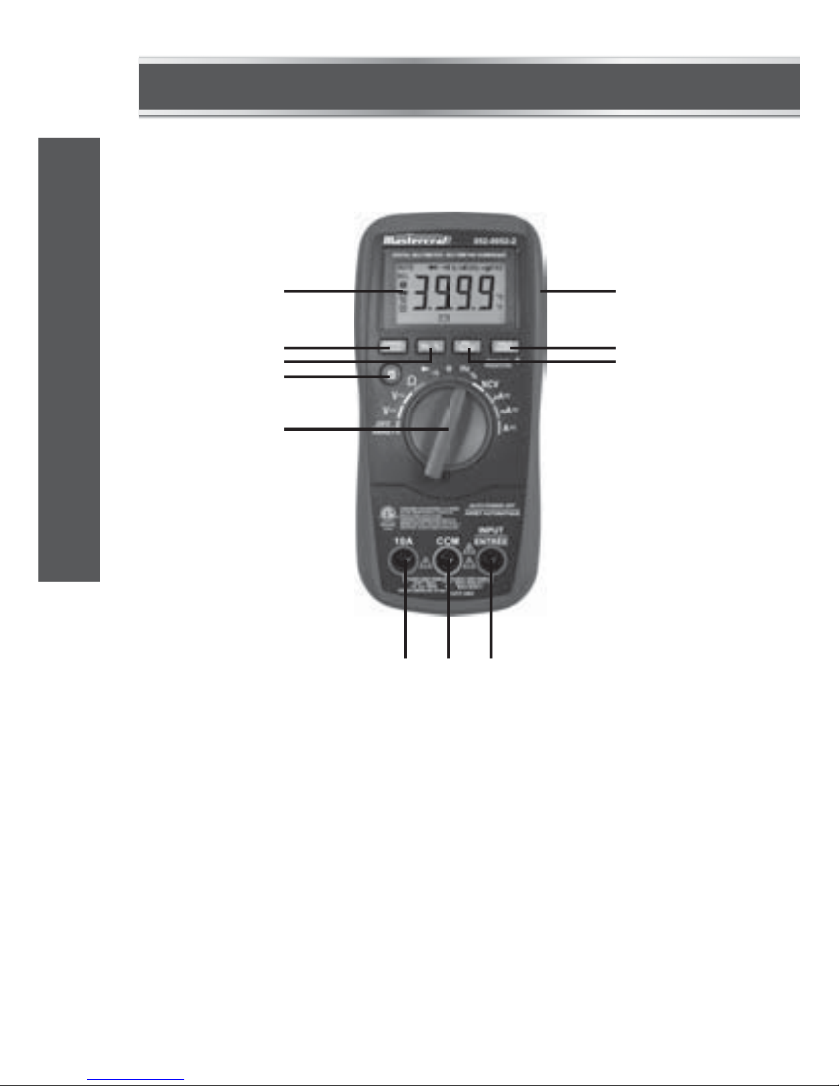
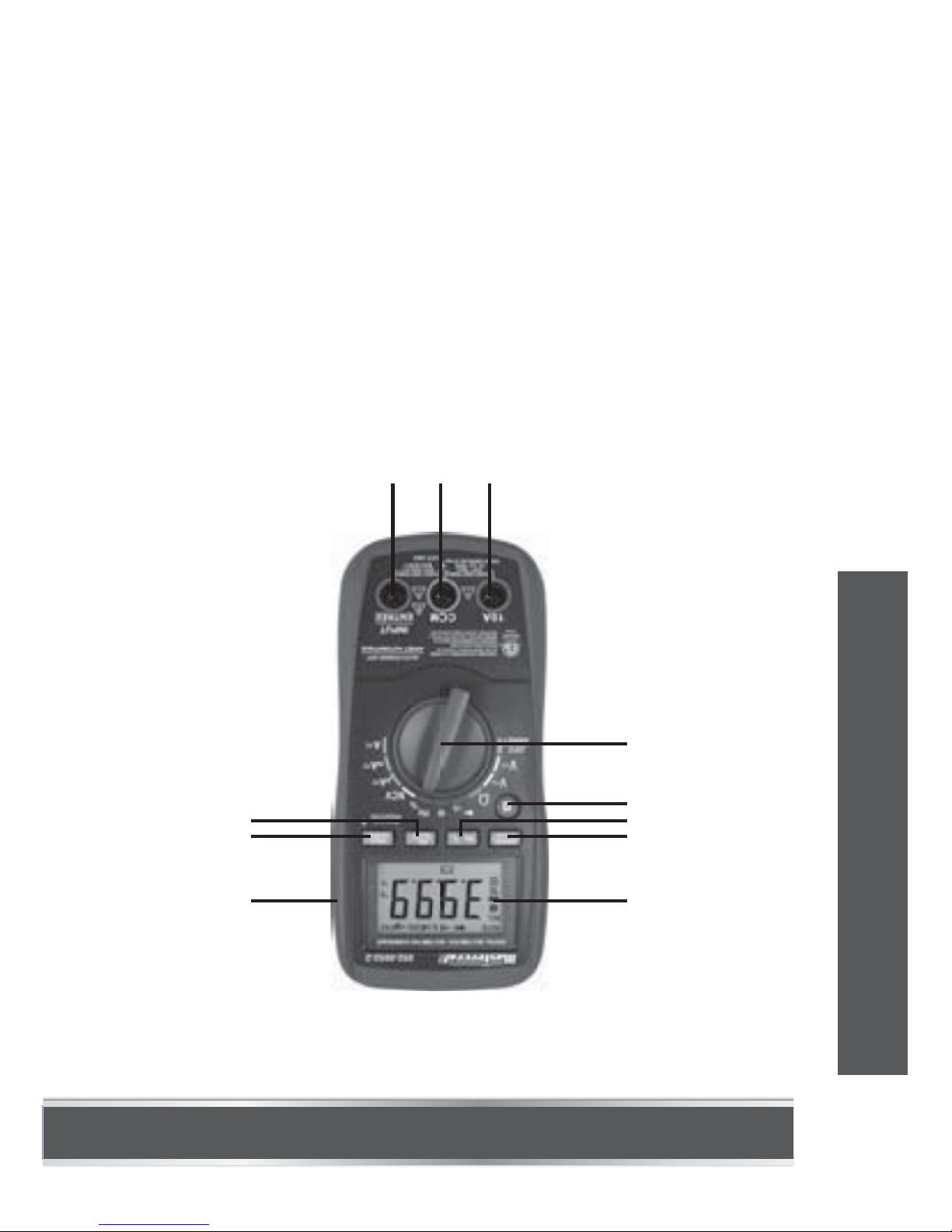
FRONT PANEL
1
2
3
4
5
678
9
10
11
1.2.Display
3 3/4 -digit LCD, with a max. reading of 3999.
"RANGE" Button
Used to switch the meter between autorange mode and manual
range mode as well as to select desired manual range.
model no. 052-0052-2 | contact us 1-800-689-9928
7
INTRODUCTION
Page 9

●
●
●
3.
4.
5.
6.
7.
8.
9.
"Hz %" Button
Used to switch the meter between frequency and duty cycle
measurements when the rotary switch is in the "Hz/%" position.
" " Button
Used to switch the meter between:
Function/Range Switch
Used to select the desired function or range as well as to turn on
or off the meter.
To save battery power, set this switch to the "OFF" position
when the meter is not in use.
"10A" Terminal
Plug-in connector for the red test lead for current
(400 mA - 10 A) measurements.
"COM" Terminal
This "COM" terminal is a plug-in connector for the black test
lead for all measurements except temperature measurements.
It is also a plug-in connector for the negative plug of a K type
thermocouple for temperature measurements.
"INPUT" Terminal
This "INPUT" terminal is a plug-in connector for the red test
lead for all measurements except temperature measurements
and current measurements ≥ 400 mA.
It is also a plug-in connector for the positive plug of a K type
thermocouple for temperature measurements.
"REL" Button
Used to enter/exit Relative mode.
AC current and DC current measurement functions.
Diode and continuity test functions.
Fahrenheit and celsius measurements.
8
INTRODUCTION
Page 10

BUILT-IN BUZZER:
10.
11.
"HOLD" Button
Press this "HOLD" button briefly to enter or exit Data Hold mode.
Press and hold down this button for about 2 secs to turn on or
off the backlight.
Holster
1.2.When you press a button, the buzzer will sound a beep if this
press is effective.
The buzzer will sound several short beeps about one minute
before the meter turns off automatically and will sound a long
beep before the meter turns off automatically.
model no. 052-0052-2 | contact us 1-800-689-9928
9
INTRODUCTION
Page 11
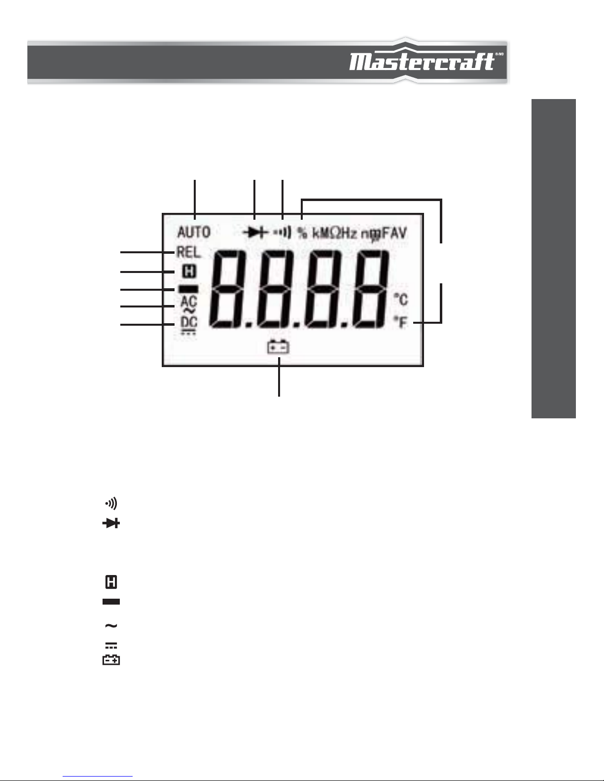
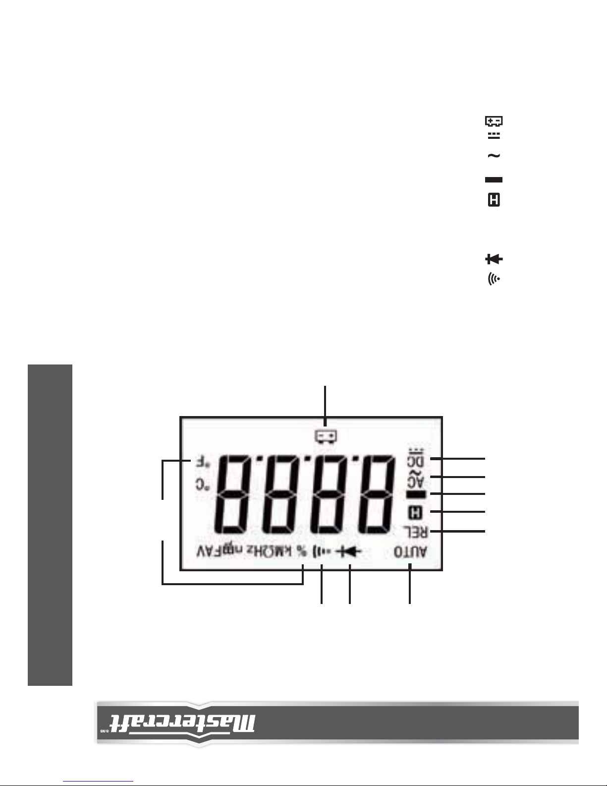
UNDERSTANDING THE DISPLAY
SYMBOL MEANING
9
10
123
4
5
6
7
8
1.
2.
3.
4.
5.
6.
7.
8.
9.
AUTO
REL
AC
DC
----- Continuity test is selected.
----- Diode test is selected.
----- Autorange mode is selected.
----- Relative mode is active.
----- Data Hold mode is active.
----- Negative sign
----- AC
----- DC
----- The battery is low and must be replaced immediately.
10
INTRODUCTION
Page 12
Warning:
To avoid false readings, which could lead to possible electric
shock or personal injury, replace the battery as soon as this low
battery indicator appears.
Units:10.
mV, V
Unit of voltage
mV: Millivolt; V: Volt;
1 V = 10
3
mV
A: Microamp;
mA: Milliamp; A: Ampere;
1 A = 10
3
mA = 106 A
: Ohm; k: Kilohm;
M: Megohm;
1 M = 10
3
k = 106
nF: Nanofarad; F: Microfarad
1 F = 10
6
F = 109 nF = 10
12
pF
ºC: Celsius degree
ºF: Fahrenheit degree
f (ºF) = 32 + 1.8 x c (ºC)
Hz: Hertz; kHz: Kilohertz;
MHz: Megahertz;
1 MHz = 10
3
kHz = 106 Hz
%: Percent
Unit of current
Unit of resistance
Unit of capacitance
Unit of temperature
Unit of frequency
Unit of duty cycle
μA, mA,
A
Ω, kΩ,
MΩ
nF, μF
ºC, ºF
Hz, kHz,
MHz
%
model no. 052-0052-2 | contact us 1-800-689-9928
11
INTRODUCTION
Page 13

GENERAL SPECIFICATIONS
Fuse Protection for "INPUT" Terminal Inputs:
400 mA/600 V FAST fuse, Min. Interrupt Rating 10000 A
Fuse Protection for "10A" Terminal Inputs:
10 A/600 V FAST fuse, Min. Interrupt Rating 10000 A
Display: 3 3/4-digit LCD with a max. reading of 3999
Overrange Indication: "OL" shown on the display
Negative Polarity Indication:
Negative sign " – " shown on the display automatically
Sampling Rate: About 2 to 3 times/sec
IP degree: IP 20
Operating Environment: Temperature: 32 to 104ºF (0 to 40ºC)
Relative Humidity: < 75%
Temperature Coefficient:
0.2 x (specified accuracy) / ºC [< 64ºF (18ºC) or > 82ºF (28ºC)]
Storage Environment: Temperature: 14 to 122ºF (-10 to 50ºC)
Relative Humidity: < 85% RH
Operating Altitude: 0 – 6560' (0 – 2000 m)
Battery: 9 V battery, 6F22 or equivalent, 1 piece
Low Battery Indication: " " shown on the display
Size: 7 1/4 x 3 1/2 x 2 7/16" (185 x 89 x 61 mm)
Weight: About 15 1/2 oz (440 g) (including battery and holster)
12
TECHNICAL SPECIFICATIONS
Page 14
TECHNICAL SPECIFICATIONS
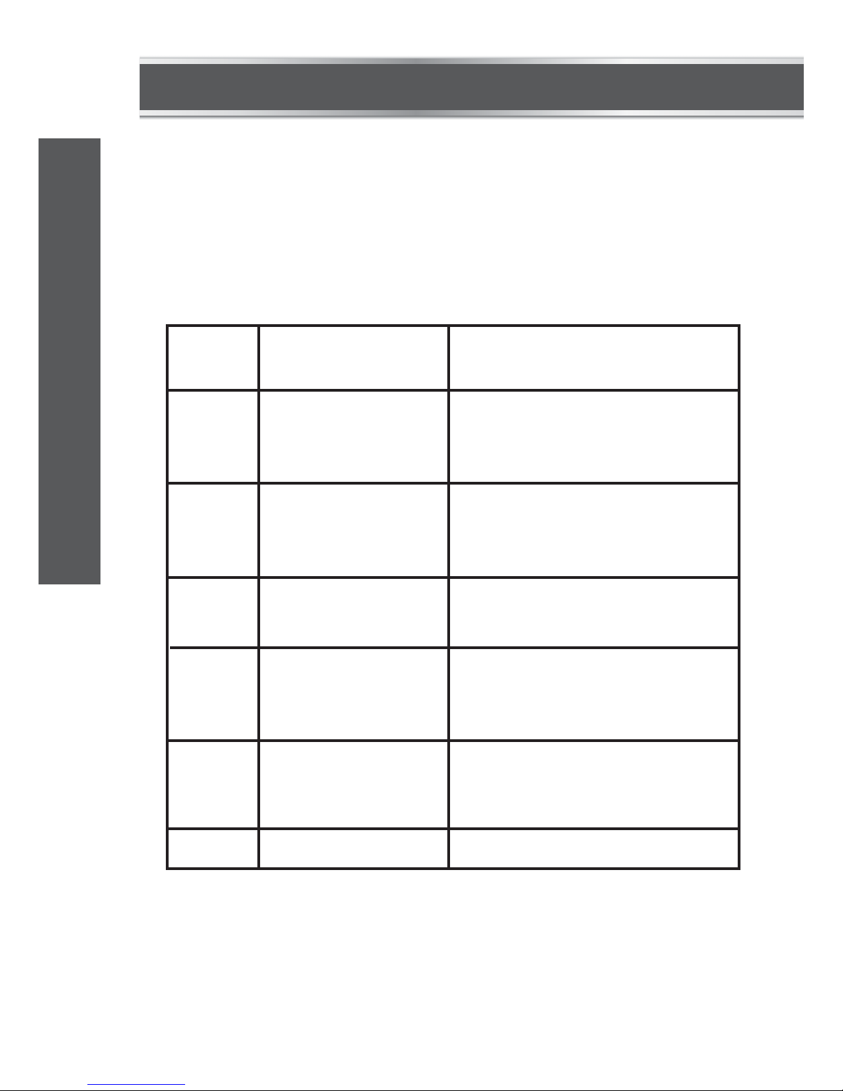
DC VOLTAGE
Readings are accurate for a period of 1 year after calibration at 64 to
82ºF (18 to 28ºC), with relative humidity up to 75%.
Accuracy specifications take the form of:
± [(% of Reading) + (Number of Least Significant Digits)]
Input Impedance: 10 M
Max. Allowable Input Voltage: 600 V DC
[1]If the voltage being measured is >600 V, the display may show
the value of the voltage, but the measurement is dangerous.
NOTE: The 600 V range is accurate from 20 to 100% of range.
Range
400 mV
4 V
40 V
400 V
600 V
± (0.8% + 5)
“OL” shown on
the display
See[1]± (1.0% + 5)
0.1 mV
1 mV
10 mV
0.1 V
1 V
Resolution Accuracy
Overrange
Indication
model no. 052-0052-2 | contact us 1-800-689-9928
13
TECHNICAL SPECIFICATIONS
Page 15
“OL” shown on
the display
“OL” shown on
the display
See[1]
Overrange
Indication
Overrange
Indication
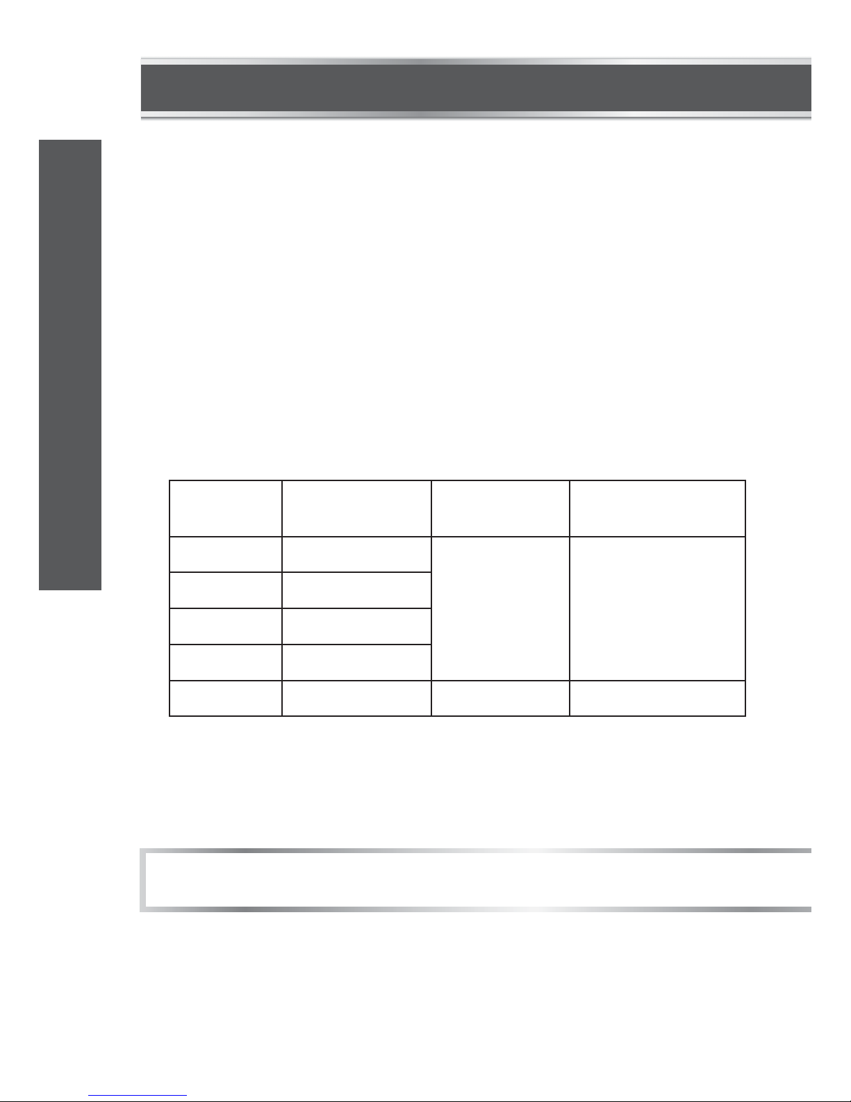
DC CURRENT
Range
400 A
4000 A
40 mA
400 mA
4 A
10 A
0.1 A
1.0 A
0.01 mA
0.1 mA
1 mA
10 mA
± (1.0% + 7)
± (1.5% + 7)
Resolution Accuracy
AC VOLTAGE
Input Impedance: 10 M
Frequency Range: 40 – 400 Hz
Response: Average, calibrated in RMS of sine wave
Max. Allowable Input Voltage: 600 V AC RMS
[1]If the voltage being measured is >600 V, the display may show
the value of the voltage, but the measurement is dangerous.
NOTE: The 600 V range is accurate from 20 to 100% of range.
Range
4 V
40 V
400 V
600 V
± (0.8% + 5)
± (1.2% + 5)
1 mV
10 mV
0.1 V
1 V
Resolution Accuracy
14
TECHNICAL SPECIFICATIONS
Page 16

“OL” shown on
the display
Overrange
Indication
Overload Protection:
400 mA/600 V FAST fuse (for protection for "INPUT" terminal inputs)
10 A/600 V FAST fuse (for protection for "10A" terminal inputs)
Max. Allowable Input Current: 10 A
(For inputs > 2 A: duration < 10 secs, interval >15 minutes)
NOTE: The 10 A range is accurate from 20 to 100% of range.
Overload Protection:
400 mA/600 V FAST fuse (for protection for "INPUT" terminal inputs)
10 A/600 V FAST fuse (for protection for "10A" terminal inputs)
Max. Allowable Input Current: 10 A
(For inputs > 2 A: duration < 10 secs, interval >15 minutes)
Frequency Range: 40 – 400 Hz
Response: Average, calibrated in RMS of sine wave
NOTE: The 10 A range is accurate from 20 to 100% of range.
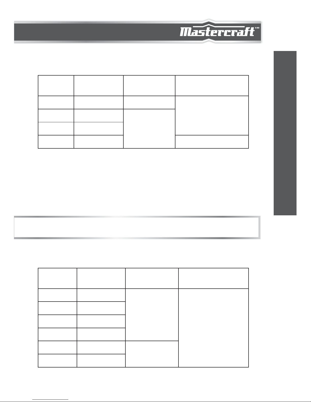
AC CURRENT
Range
400 A
4000 A
40 mA
400 mA
4 A
10 A
0.1 A
1.0 A
0.01 mA
0.1 mA
1 mA
10 mA
± (1.8% + 10)
± (2.5% + 10)
Resolution
Accuracy
model no. 052-0052-2 | contact us 1-800-689-9928
15
TECHNICAL SPECIFICATIONS
Page 17

“OL” shown on
the display
Overrange
Indication
Open Circuit Voltage: < 0.7 V
RESISTANCE
Range
400
4 k
40 k
400 k
4 M
40 M
0.1
1
10
100
1 k
10 k
± (1.0% + 5)
± (3.0% + 10)
± (1.5% + 5)
Resolution Accuracy
Input Voltage: 1 – 20 V RMS
NOTE: Frequency measurements are autoranging.
FREQUENCY
Range
9.999 Hz
99.99 Hz
999.9 Hz
9.999 kHz
99.99 kHz
999.9 kHz
9.999 MHz
0.001 Hz
0.01 Hz
0.1 Hz
1 Hz
10 Hz
100 Hz
1 kHz
± (1.0% + 5)
not specified
Auto-range
Resolution Accuracy Remark
16
TECHNICAL SPECIFICATIONS
Page 18

NOTE: Use Relative mode to subtract the residual capacitance of the
test leads and the meter.
If the capacitance being measured is > 1000 µF, the display
may show a reading, but the measurement error may be
large. If the capacitance being measured is > 4000 µF, “OL”
will be shown on the display.
CAPACITANCE
Range
40 nF
400 nF
4 F
40 F
400 F
1000 F
10 pF
100 pF
1 nF
10 nF
100 nF
1 F
± (2.5% + 5)
± (3.5% + 5)
± (4.0% + 5)
± (3.5% + 20)
not specified
± (5.0% + 5)
Resolution Accuracy
Input Voltage: 4 – 10 V P-P
Frequency Range: 4 Hz – 1 kHz
DUTY CYCLE
Range
5 – 95% 0.1% Auto-range
Resolution Remark
Auto-range
Remark
± ( 2.0% + 7 )
Accuracy
model no. 052-0052-2 | contact us 1-800-689-9928
17
TECHNICAL SPECIFICATIONS
Page 19

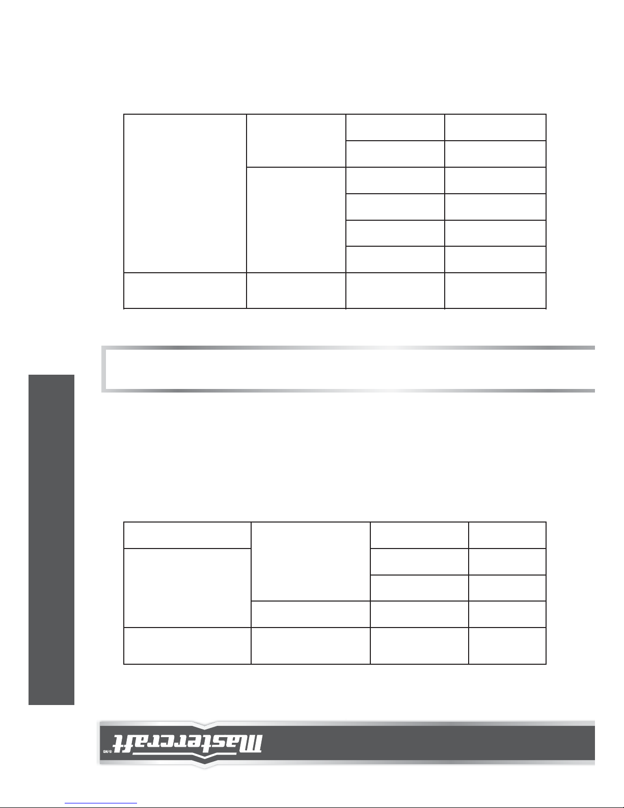
1.
CONTINUITY
OPERATING INSTRUCTIONS
USING RELATIVE MODE
Relative mode is available in some functions. Selecting relative mode
causes the meter to store the present reading as a reference for
subsequent measurements.
Press the "REL" button. The meter enters Relative mode and
stores the present reading as a reference for subsequent
measurements. The symbol "REL" appears as an indicator and
the display reads zero.
Range
The built-in buzzer will sound if the resistance
is less than about 20 .
The buzzer may or may not sound if the
resistance is between 20 and 150 .
The buzzer will not sound if the resistance is
more than 150 .
Description
DIODE
Range
The display shows the
approx. forward voltage
drop of the diode.
Open Circuit Voltage:
about 3 V
Test Current: about 0.8 mA
Description Remark
18
OPERATING INSTRUCTIONS
Page 20

DATA HOLD MODE
Press the HOLD button to hold the present reading on the display.
" " appears on the display as an indicator. To exit Data Hold mode,
just press this button again. " " disappears.
MANUAL RANGING AND AUTORANGING
The meter defaults to autorange mode in measurement functions
which have both autorange mode and manual range mode. When the
meter is in autorange mode, the symbol "AUTO" is displayed.
2.3.When you perform a new measurement, the display shows the
difference between the reference and the new measurement.
To exit Relative mode, just press the "REL" button again. The
symbol "REL" disappears.
1.2.Press the RANGE button. The meter enters manual range mode
and the symbol "AUTO" disappears.
Each press of the RANGE button increases the range. After the
highest range, the meter wraps to the lowest range.
To exit manual range mode, press and hold down the
RANGE
button for more than about 2 seconds. The meter returns
to
autorange mode and "AUTO" is displayed.
NOTE:
When in Relative mode, the actual value of the object under test must
not exceed the full-scale value of the selected range. Use a higher
measurement range if necessary.
model no. 052-0052-2 | contact us 1-800-689-9928
19
OPERATING INSTRUCTIONS
Page 21

MEASURING DC VOLTAGE
1.
2.
3.
4.
1.
2.
Connect the black test lead to the "COM" terminal and the red
test lead to the "INPUT" terminal.
Set the function switch to the V position.
Connect the test leads across the source or circuit to be tested.
Read the reading on the display. The polarity of the red lead
connection will be indicated as well.
NOTE:
To avoid electric shock to you or damage to the meter, do not
apply a voltage higher than 600 V between terminals.
In manual range mode, when the display shows “OL”, a higher
range should be selected.
20
OPERATING INSTRUCTIONS
Page 22

MEASURING AC VOLTAGE
1.
2.
3.
4.
Connect the black test lead to the "COM" terminal and the red
test lead to the "INPUT" terminal.
Set the function switch to the V position.
Connect the test leads across the source or circuit to be tested.
Read the reading on the display.
1.
2.
NOTE:
To avoid electric shock to you or damage to the meter, do not
apply a voltage higher than 600 V between terminals.
In manual range mode, when the display shows “OL”, a higher
range should be selected.
model no. 052-0052-2 | contact us 1-800-689-9928
21
OPERATING INSTRUCTIONS
Page 23

MEASURING DC OR AC CURRENT
1.
2.
3.
4.
Connect the black test lead to the "COM" terminal. If the current
to be measured is less than 400 mA, connect the red test lead
to the "INPUT" terminal. If the current is between 400 mA
and
10 A, connect the red test lead to the "10A" terminal instead.
Set the function switch to A , mA , or μA range position.
Press the button to select DC or AC current measurement.
The display will show the corresponding symbol as an
indication.
Turn off power to the circuit to be tested, and then discharge all
capacitors.
22
OPERATING INSTRUCTIONS
Page 24

5.
6.
1.
2.
Break the circuit path to be tested, and connect the test leads in
series with the circuit.
Turn on power to the circuit, then read the display. For DC
current measurements, the polarity of the red test lead connection will be indicated as well.
NOTE:
If you don't know the magnitude of the current to be measured
beforehand, select the highest range first and then reduce it
range by range until satisfactory resolution is obtained.
In manual range mode, when the display shows “OL”, a higher
range should be selected.
model no. 052-0052-2 | contact us 1-800-689-9928
23
OPERATING INSTRUCTIONS
Page 25
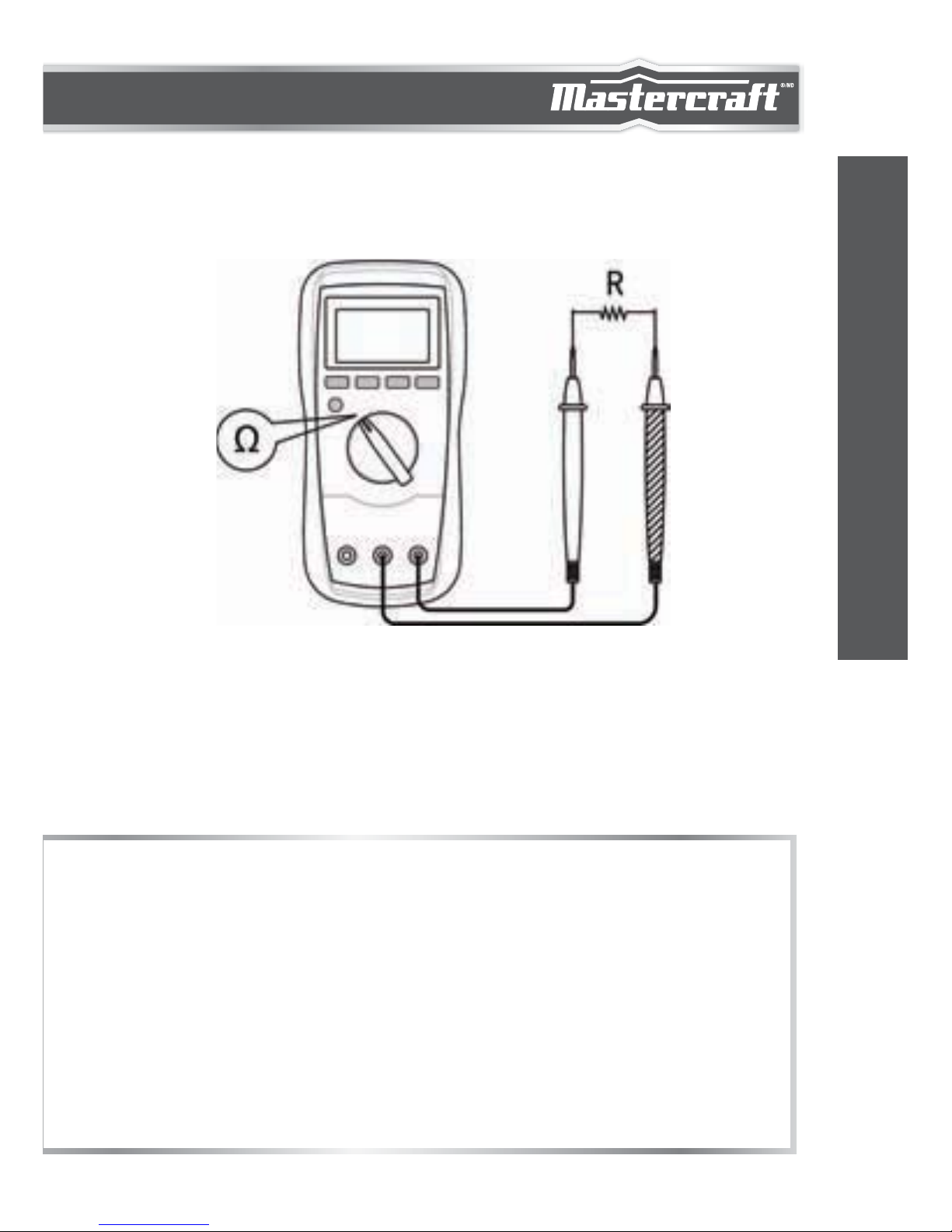
MEASURING RESISTANCE
1.
2.
3.
4.
Connect the black test lead to the "COM" terminal and
the red test lead to the "INPUT" terminal.
Set the function switch to Ω position.
Connect the test leads across the object to be tested.
Read the reading on the display.
1.
2.
3.
4.
For measurements > 1 M, the meter may take a few seconds
to stabilize reading. This is normal for high resistance measurements.
When the input is not connected, i.e. at open circuit, "OL" will be
displayed as an overrange indication.
Before measurement, disconnect all power to the circuit to be
tested and discharged all capacitors thoroughly.
In manual range mode, when the display shows “OL”, a higher
range should be selected.
NOTE:
24
OPERATING INSTRUCTIONS
Page 26
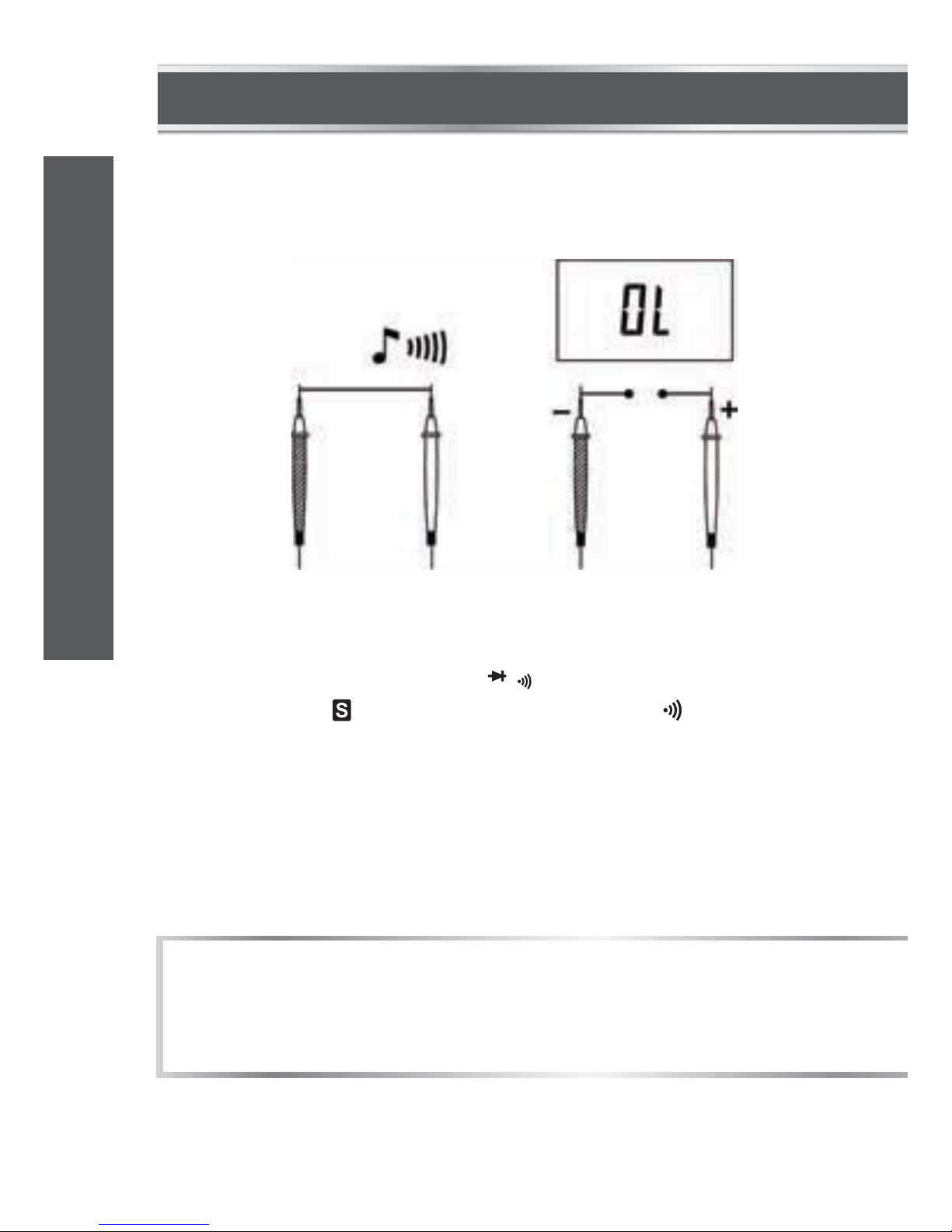
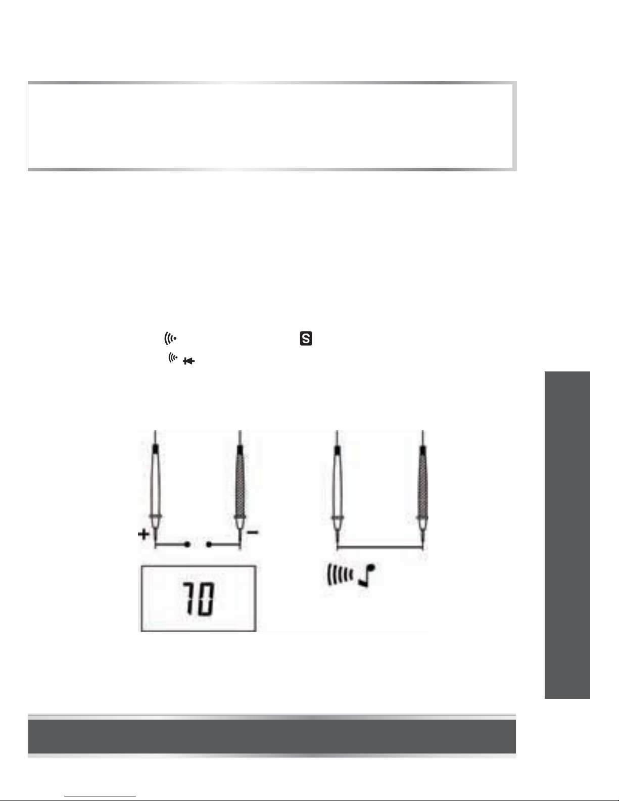
CONTINUITY TEST
1.
2.
3.
4.
5.
Connect the black test lead to the "COM" terminal and the red
test lead to the "INPUT" terminal.
Set the function switch to / position.
Press the button until the display shows " ".
Connect the test leads across the circuit to be tested.
The display shows the resistance value. If the resistance is less
than about 20 , the built-in buzzer will sound. If the resistance
is between 20 and 150 , the buzzer may or may not sound.
If the resistance is more than 150 , the buzzer will not sound.
NOTE:
Before test, disconnect all power to the circuit to be tested and
discharge all capacitors thoroughly.
model no. 052-0052-2 | contact us 1-800-689-9928
25
OPERATING INSTRUCTIONS
Page 27

DIODE TEST
1.
2.
3.
4.
5.
Connect the black test lead to the "COM" terminal and the red
test lead to the "INPUT" terminal. (Note: The polarity of the red
lead is positive " + " .)
Set the function switch to / position.
Press the button until the display shows " ".
Connect the red test lead to the anode of the diode to be tested
and the black test lead to the cathode of the diode.
The display shows the approximate forward voltage drop of the
diode. If the connection is reversed, "OL" will be shown on the
display.
26
OPERATING INSTRUCTIONS
Page 28

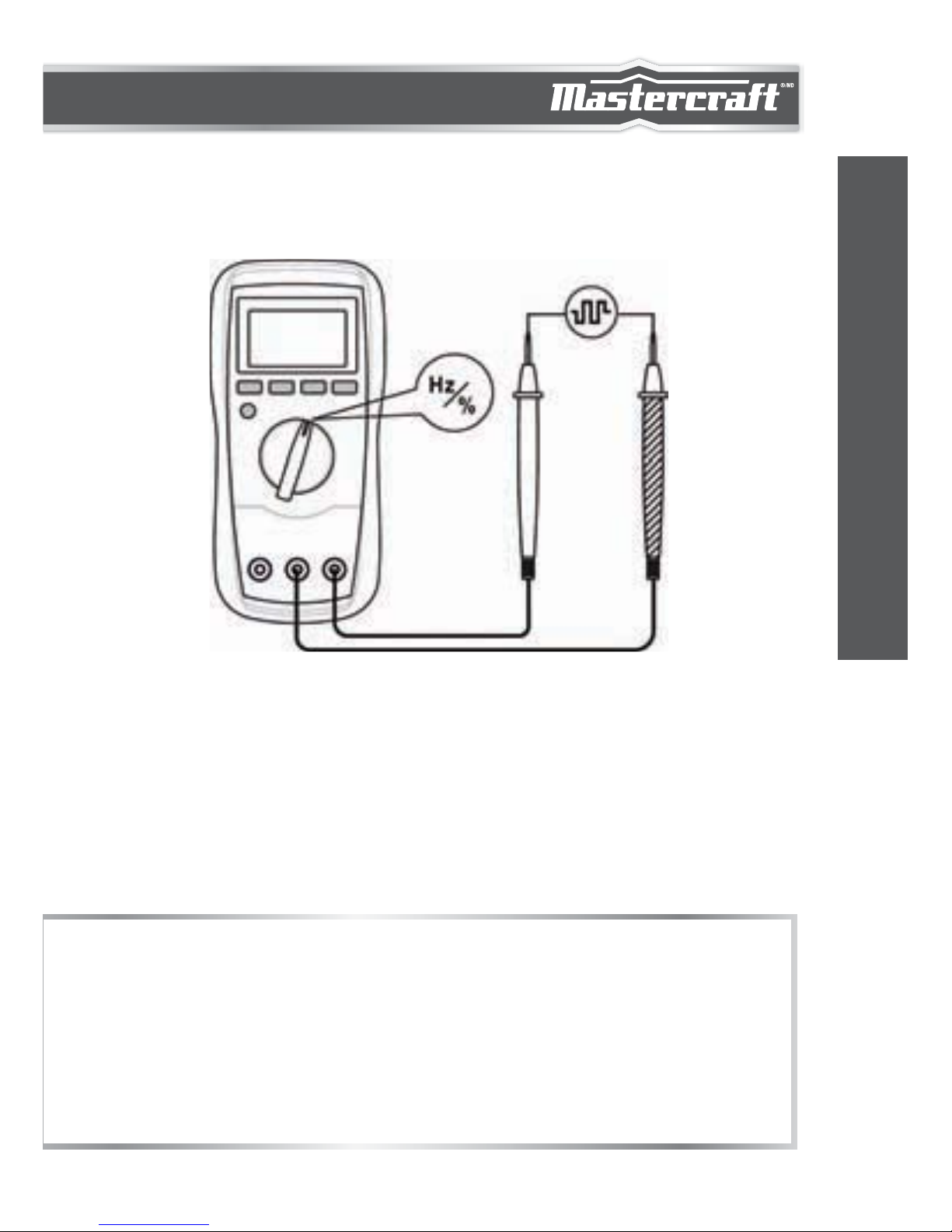
MEASURING FREQUENCY
1.
2.
3.
4.
Connect the black test lead to the "COM" terminal and the red
test lead to the "INPUT" terminal.
Set the function switch to Hz/% position. Then press the "Hz %"
button until the display shows "Hz".
Connect the test leads across the source or circuit to be tested.
Read the reading on the display.
1.
2.
3.
For frequency measurements, the range exchange is automatic,
and measurement range is: 0 – 10 MHz.
The voltage of input signal should be between 1 and 20 V RMS
.
The higher the frequency, the higher the required input voltage.
For measurements < 10 Hz, the amplitude of input signal must
be more than 2 V RMS.
NOTE:
model no. 052-0052-2 | contact us 1-800-689-9928
27
OPERATING INSTRUCTIONS
Page 29
MEASURING DUTY CYCLE
1.
2.
3.
4.
5.
Connect the black test lead to the "COM" terminal and the red
test lead to the "INPUT" terminal.
Set the function switch to Hz/% position.
Press the "Hz %" button until the display shows "%".
Connect the test leads to the circuit to be tested.
The reading on the display is the duty cycle value of the square
wave being measured.
1.2.The voltage of the input signal should be between 4 and 10 V
P-P.
After you remove the measured signal, its reading may still
remain on the display. Pressing the "Hz %" button twice will
zero the display.
NOTE:
28
OPERATING INSTRUCTIONS
Page 30
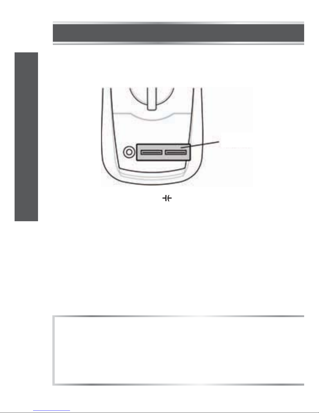
MEASURING CAPACITANCE
1.
2.
3.
4.
5.
Set the function switch to position.
Connect the adaptor to the "COM" and "INPUT" terminals, as
indicated in the figure.
If the display does not read zero, press the REL button to zero
the display; the meter will enter Relative mode and the symbol
"REL" will appear on the display as an indicator.
Discharge thoroughly the capacitor which you will test by
shorting its two leads together. Then insert the two leads of the
capacitor into the two jacks of the adaptor. (Make sure the
polarity connection is correct.)
Wait until the reading is stable, then read the reading on the display.
1.
2.
For capacitance measurements, the range exchange is automatic.
Because the meter measures capacitance by measuring the
time of charging and discharging the capacitor, measuring a
higher capacitance will take more time.
NOTE:
Adaptor
model no. 052-0052-2 | contact us 1-800-689-9928
29
OPERATING INSTRUCTIONS
Page 31
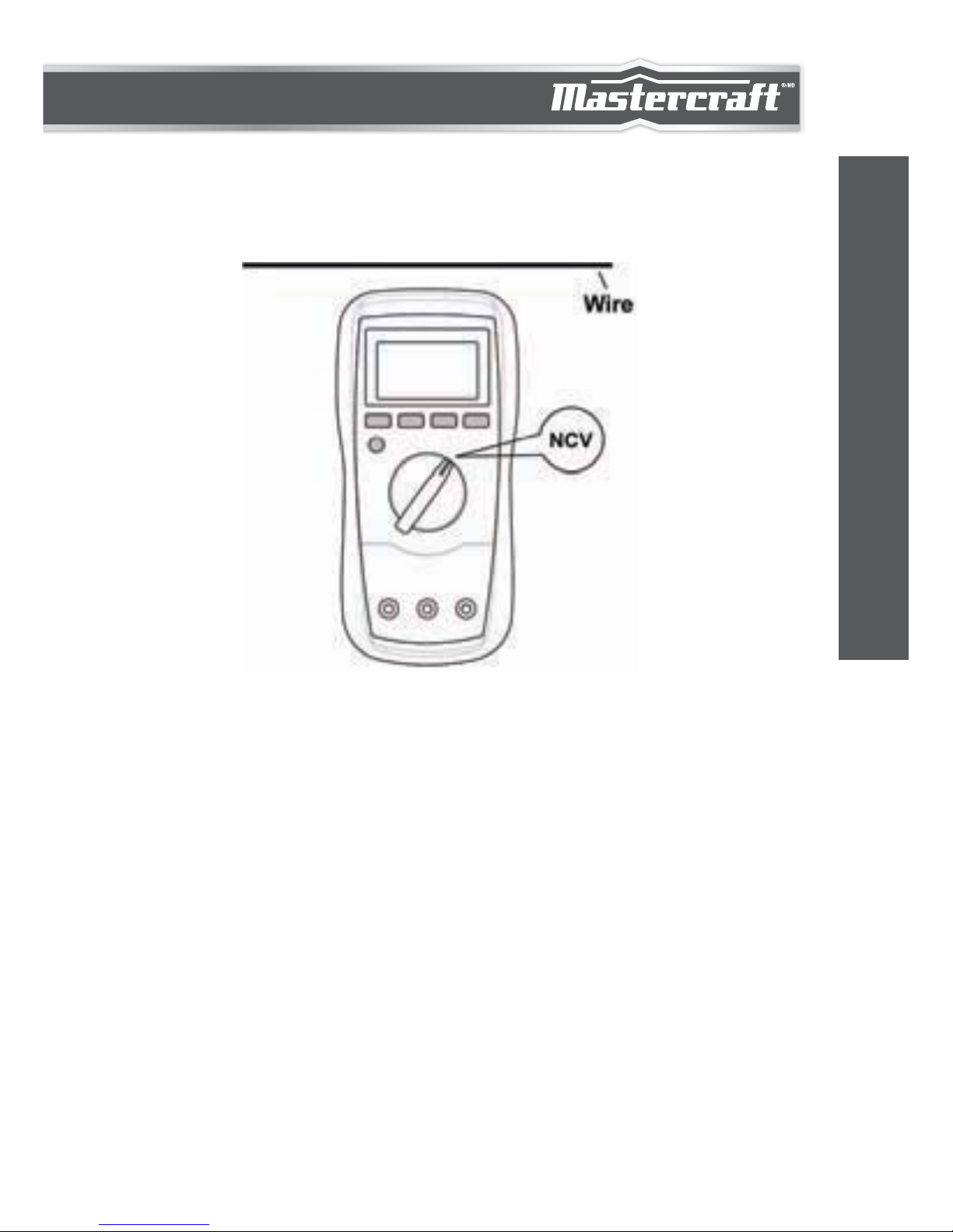
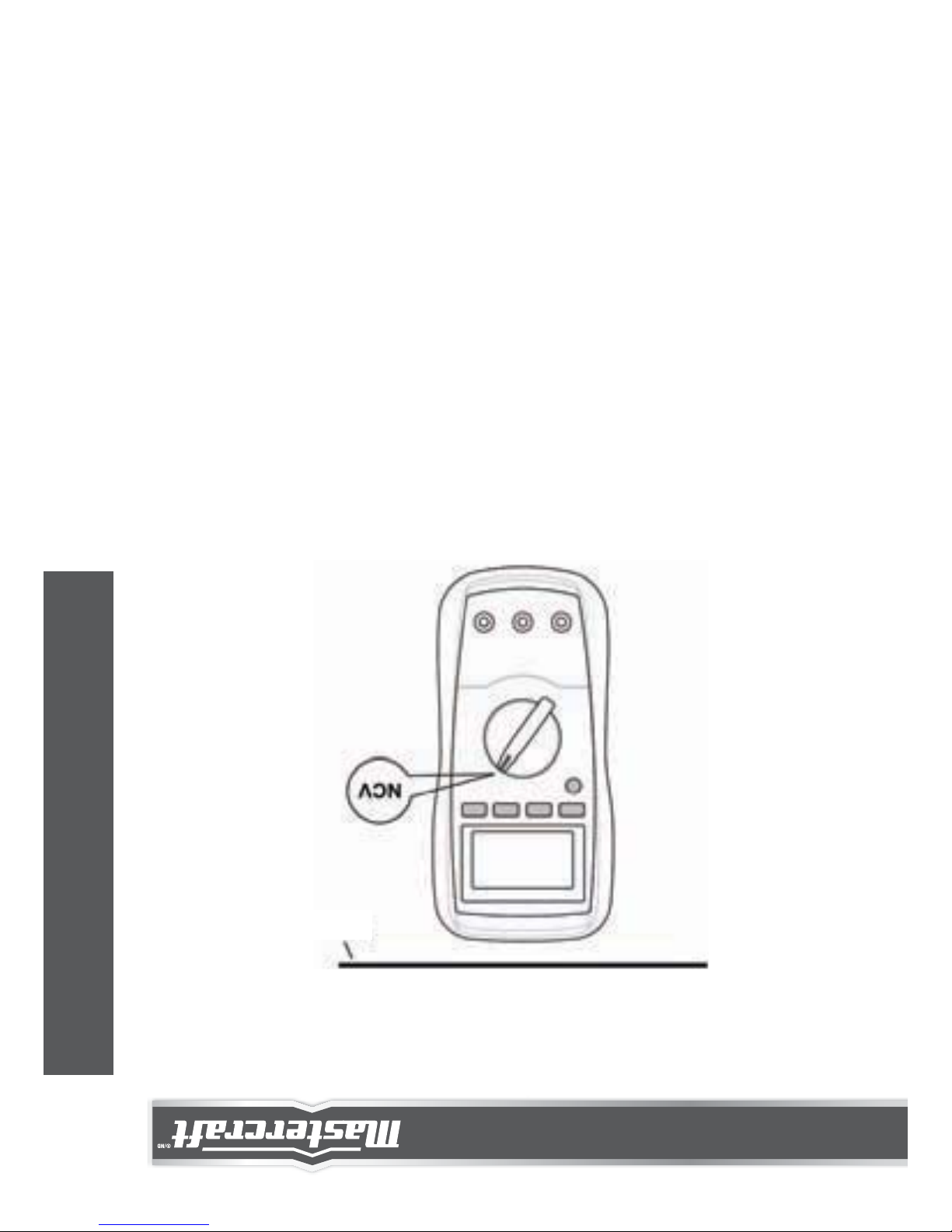
NON-CONTACT AC VOLTAGE DETECTION
1.
2.
3.
Make sure that the meter has been turned on, then set the
function switch to NCV position.
Move the top of the meter close to the object to be tested.
When the meter detects AC voltage, the built-in buzzer will
sound. (Note: The reading on the display is meaningless and
can not be used.)
30
OPERATING INSTRUCTIONS
Page 32

WARNING
AUTOMATIC POWER-OFF
1.
2.
3.
4.
5.
When you just set the function switch to NCV position, the
built-in buzzer may sound several beeps. This is normal and
does not affect subsequent detections.
Because of the meter's detection limit, a line (or conductor)
under test may be live even if the built-in buzzer does not sound.
Before use, verify the meter's operation by detecting a known
AC voltage.
When the meter is interfered with by electric field in environment, it will give alarm even if the object under test does not
contain AC voltage.
To avoid electric shock, don't touch any conductor with hand or skin.
The display will blank and the meter will go into Sleep mode if you
have not turned the function switch or pressed a button for about 15
minutes. You can press a button to arouse the meter from Sleep.
To disable the automatic power-off feature, press and hold down a
button while rotating the function switch from the "OFF" position to
another switch position.
model no. 052-0052-2 | contact us 1-800-689-9928
31
OPERATING INSTRUCTIONS
Page 33

MAINTENANCE
GENERAL MAINTENANCE
1.
2.
3.
4.
Set the rotary switch to OFF position and remove all test leads
from the meter.
Shake out any dirt which may exist in the terminals.
Soak a new swab with alcohol.
Work the swab around in each terminal.
Except replacing fuse and battery, never attempt to repair or service
the meter unless you are qualified to do so and have the relevant
calibration, performance test, and service instructions.
Store the meter in a dry place when not in use. Don't store it in an
intense electromagnetic field environment.
Periodically wipe the case with a damp cloth and a little mild
detergent. Do not use abrasives or solvents.
Dirt or moisture in the terminals can affect readings. Clean the
terminals as follows:
If the meter fails, check and replace (as needed) the battery and
fuses, and/or review this manual to verify proper use of the meter.
32
MAINTENANCE
Page 34

BATTERY AND FUSE REPLACEMENT
F1.
F2.
400 mA/600 V FAST fuse, ø6.35X32 mm, Min Interrupt Rating
10000 A
10 A/600 V FAST fuse, ø6.35X32 mm, Min Interrupt Rating
10000 A
Warning:
To avoid false readings, which could lead to possible electric shock
or personal injury, replace the battery as soon as the low battery
indicator ( ) appears.
To prevent damage or injury, install only replacement fuses with the
specified amperage, voltage, and interrupt ratings.
Remove the test leads before opening the battery cover or the case.
To Replace Battery:
Remove the screw on the battery cover and remove the battery
cover. Replace the exhausted battery with a new one of the same
type. Reinstall the battery cover and the screw.
To Replace Fuse:
Remove the holster from the meter, then remove the screws on the
back cover and move the back cover aside gently. Replace the blown
fuse with a new one of the same ratings. Reinstall the back cover and
all the screws. Finally, reinstall the holster.
This meter uses two fuses:
model no. 052-0052-2 | contact us 1-800-689-9928
33
MAINTENANCE
Page 35

ACCESSORIES
NOTE:
1.
2.
3.
This manual is subject to change without notice.
Our company will not take responsibility for any loss.
The contents of this manual can not be used as the reason to use
the meter for any special application.
DISPOSAL OF THIS ARTICLE
Dear Customer,
If you at some point intend to dispose of this article,
then please keep in mind that many of its
components consist of valuable materials, which
can be recycled.
Please do not dispose of it in the garbage bin, but
check with your local council for recycling facilities
in your area.
Test Lead: 1 pair
Manual: 1 piece
Adaptor: 1 piece
34
WARRANTY
This Mastercraft product carries a one-year warranty against defects
in workmanship and materials. This product is not guaranteed
against wear, breakage or misuse.
WARRANTY
Page 36

Page 37

Page 38
ACCESSOIRES
REMARQUE
1.
2.
3.
Ce guide d'utilisation peut être modifié à tout moment sans préavis.
Notre société n'est pas responsable en cas de perte.
Le contenu de ce guide ne peut être appliqué pour utiliser le
multimètre de toute autre manière que ce soit.
ÉLIMINATION DU PRODUIT
Chers clients,
Si vous avez l'intention à un moment donné de jeter
cet article, alors veuillez garder à l'esprit qu'un bon
nombre de ses composants sont constitués de
matériaux précieux, qui peuvent être recyclés.
Veuillez ne pas le jeter à la poubelle, mais consultez
votre conseil municipal pour connaître les
installations de recyclage dans votre région.
Fils d'essai : 2
Guide d'utilisation : 1
Adaptateur : 1
34
ENTRETIEN
GARANTIE
Cet article Mastercraft comprend une garantie de un (1) an contre les
défauts de fabrication et de matériau(x). Exclusion : usure ou bris
causés par un usage abusif ou inapproprié.
Page 39

REMPLACEMENT DE LA PILE ET DES FUSIBLES
F1.
F2.
400 mA/600 V action rapide, ø6,35 X 32 mm, pouvoir de coupure
min. 10 000 A
10 A/600 V action rapide,
ø
6,35 X 32 mm, pouvoir de coupure
min. 10 000 A
Avertissement :
Pour éviter les erreurs de lecture pouvant mener à d'éventuels chocs
électriques ou blessures, remplacez la pile dès que l'indicateur de
pile faible ( ) apparaît.
Pour éviter tout dommage ou blessure, utilisez uniquement des
fusibles de rechange dont l'intensité, la tension et le pouvoir de
coupure sont conseillés dans ce guide.
Retirez les fils d'essai avant d'ouvrir le couvercle ou le compartiment
de la pile.
Pour remplacer la pile :
Retirez la vis sur le couvercle de la pile, puis retirez le couvercle de
la pile. Remplacez la pile usagée par une pile de même type.
Replacez le couvercle de la pile et la vis.
Pour remplacer un fusible :
Retirez l'étui du multimètre, puis retirez les vis du couvercle arrière
et retirez délicatement le couvercle. Remplacez le fusible grillé par
un nouveau fusible similaire. Replacez le couvercle arrière et les vis.
Enfin, replacez l'étui.
Ce multimètre fonctionne avec deux fusibles :
N° de modèle : 052-0052-2 | Communiquez avec nous au 1 800 689-9928
33
ENTRETIEN
Page 40

ENTRETIEN
ENTRETIEN GÉNÉRAL
1.
2.
3.
4.
Mettez la molette en position ARRÊT et retirez les fils d'essai du
multimètre.
Évacuez toute saleté qui pourrait s'être logée dans les bornes.
Imbibez d'alcool un coton propre.
Passez le coton autour de chaque borne.
À l'exception du remplacement des fusibles et de la pile, n'essayez
pas de réparer le multimètre par vous-même, à moins que vous
soyez qualifié pour le faire et que vous ayez les instructions relatives
à la calibration, au test de fonctionnement et à la réparation.
Rangez le multimètre dans un endroit sec lorsque vous ne l'utilisez
pas. Ne le rangez pas à proximité d'un fort champ électromag-
nétique.
Essuyez le boîtier périodiquement avec un chiffon humide et un peu
de nettoyant doux. N'utilisez pas d'abrasifs ou de solvants.
La saleté ou l'humidité dans les bornes peuvent affecter la lecture
des résultats. Nettoyez les bornes de la manière suivante :
Si le multimètre ne semble pas fonctionner correctement, vérifiez et
remplacez (au besoin) la pile ou les fusibles, ou lisez ce guide
d'utilisation pour vérifier que vous l'utilisez correctement.
32
ENTRETIEN
Page 41

AVERTISSEMENT
ARRÊT AUTOMATIQUE
1.
2.
3.
4.
5.
Lorsque la molette est en position NCV, il est possible que
l'alarme émette plusieurs bips. Il s'agit d'un comportement
normal, qui n'aura aucune incidence sur vos futures détections.
En raison des limites de détection du multimètre, il se peut
qu'une ligne (ou un conducteur) testée soit chargée, même si
l'alarme ne sonne pas.
Avant d'utiliser le multimètre, vérifiez qu'il fonctionne en
détectant une tension CA connue.
Lorsque le multimètre est brouillé par un champ électrique,
l'alarme sonnera même si l'objet testé ne contient pas de
tension CA.
Pour éviter tout choc électrique, ne touchez aucun fil conducteur
avec la main ou la peau.
L'écran s'éteint et le multimètre passe en mode Veille si vous n'avez
pas tourné la molette ni appuyé sur un bouton depuis environ 15
minutes. Pour quitter le mode Veille, appuyez sur un bouton.
Pour désactiver l'arrêt automatique, maintenez un bouton enfoncé
tout en faisant passer la molette de la position « ARRÊT » à une autre
position.
N° de modèle : 052-0052-2 | Communiquez avec nous au 1 800 689-9928
31
CONSIGNES D’UTILISATION
Page 42
DÉTECTION DE TENSION CA SANS CONTACT
1.
2.
3.
Assurez-vous que le multimètre est en marche, puis sélection-
nez la fonction NCV.
Placez le dessus du multimètre près de l'objet à tester.
Lorsque le multimètre détecte une tension CA, l'alarme intégrée
sonnera. (Remarque : Le résultat affiché sur l'écran est
insignifiant et ne peut être utilisé.)
Fil
30
CONSIGNES D’UTILISATION
Page 43

MESURE DE LA CAPACITÉ
1.
2.
3.
4.
5.
Mettez la molette de sélection en position « ».
Branchez l'adaptateur dans les bornes « COM » et « ENTRÉE »,
comme illustré.
Si l'écran n'indique pas zéro, appuyez sur le bouton « REL »
pour effectuer une remise à zéro. Le multimètre passera alors
en mode Relatif et le symbole « REL » s'affichera.
Déchargez soigneusement le condensateur à vérifier en
court-circuitant ses deux fils ensemble. Insérez ensuite les deux
fils du condensateur dans les deux bornes de l'adaptateur.
(Assurez-vous que les polarités sont correctes.)
Attendez que le résultat affiché soit stable.
1.
2.
Pour les mesures de capacité, le changement de calibre est
automatique.
Puisque le multimètre indique la capacité en mesurant le temps de
charge et de décharge du condensateur, il lui faudra plus de temps
pour mesurer une capacité élevée.
Remarque :
Adaptateur
N° de modèle : 052-0052-2 | Communiquez avec nous au 1 800 689-9928
29
CONSIGNES D’UTILISATION
Page 44

MESURE DU CYCLE DE SERVICE
1.
2.
3.
4.
5.
Branchez le fil d'essai noir dans la borne « COM » et le fil d'essai
rouge dans la borne « ENTRÉE ».
Mettez la molette de sélection en position « Hz/% ».
Appuyez sur le bouton « Hz % » jusqu'à ce que « % » apparaisse
sur l'écran.
Branchez les fils d'essai sur le circuit à tester.
Le résultat qui s'affiche sur l'écran correspond au cycle de
service de l'onde carrée mesurée.
1.
2.
La tension du signal d'entrée doit se situer entre 4 et 10 V C-C.
Après avoir supprimé le signal mesuré, il se peut que le résultat
reste affiché sur l'écran. Appuyez deux fois sur le bouton « Hz % »
pour que zéro s'affiche.
Remarque :
28
CONSIGNES D’UTILISATION
Page 45

MESURE DE LA FRÉQUENCE
1.
2.
3.
4.
Branchez le fil d'essai noir dans la borne « COM » et le fil d'essai
rouge dans la borne « ENTRÉE ».
Mettez la molette de sélection en position « Hz/% ». Appuyez
ensuite sur le bouton « Hz % » jusqu'à ce que « Hz » apparaisse
sur l'écran.
Branchez les fils d'essai dans la source ou le circuit à vérifier.
Lisez le chiffre affiché sur l'écran.
1.
2.
3.
Pour les mesures de fréquence, le changement de calibre est
automatique et la gamme de mesure est 0-10 MHz.
La tension du signal d'entrée doit se situer entre 1 et 20 V RMS.
Plus la fréquence est élevée, plus la tension d'entrée requise
doit être élevée.
Pour les mesures inférieures à 10 Hz, l'amplitude du signal
d'entrée doit être supérieure à 2 V RMS.
Remarque :
N° de modèle : 052-0052-2 | Communiquez avec nous au 1 800 689-9928
27
CONSIGNES D’UTILISATION
Page 46

TEST DE DIODE
1.
2.
3.
4.
5.
Branchez le fil d'essai noir dans la borne « COM » et le fil d'essai
rouge dans la borne « ENTRÉE ». (Remarque : La polarité du fil
rouge est positive « + »).
Mettez la molette de sélection en position« / ».
Appuyez sur le bouton « »jusqu'à ce que « » apparaisse
sur l'écran.
Branchez le fil d'essai rouge dans l'anode de la diode à vérifier
et le fil d'essai noir dans la cathode de la diode.
L'écran affiche la chute de tension directe approximative de la
diode. Si le branchement est inversé, « OL » s'affichera sur
l'écran.
26
CONSIGNES D’UTILISATION
Page 47
TEST DE CONTINUITÉ
1.
2.
3.
4.
5.
Branchez le fil d'essai noir dans la borne « COM » et le fil d'essai
rouge dans la borne « ENTRÉE ».
Mettez la molette de sélection en position « / ».
Appuyez sur le bouton « » jusqu'à ce que « » apparaisse
sur l'écran.
Branchez les fils d'essai sur le circuit à tester.
L'écran indique la résistance. Si la résistance est inférieure à
environ 20 , l'alarme intégrée retentira. Si la résistance se
situe entre 20 et 150 , l'alarme sonnera ou non. Si la
résistance est supérieure à 150 , l'alarme ne retentira pas.
Remarque :
Avant de procéder à la vérification, coupez le circuit électrique et
déchargez soigneusement tous les condensateurs.
N° de modèle : 052-0052-2 | Communiquez avec nous au 1 800 689-9928
25
CONSIGNES D’UTILISATION
Page 48

MESURE DE LA RÉSISTANCE
1.
2.
3.
4.
Branchez le fil d'essai noir dans la borne « COM » et le fil d'essai
rouge dans la borne « ENTRÉE ».
Mettez la molette de sélection en position Ω.
Branchez les fils d'essai sur l'objet à tester.
Lisez le chiffre affiché sur l'écran.
1.
2.
3.
4.
Pour les mesures supérieures à 1 M, il se peut que le
multimètre ait besoin de quelques secondes pour se stabiliser.
Ce comportement est normal lorsque des résistances élevées
sont mesurées.
Lorsque l'entrée n'est pas branchée (p. ex., circuit ouvert), « OL »
s'affichera pour indiquer un dépassement.
Avant de procéder à une mesure, coupez le circuit électrique et
déchargez soigneusement tous les condensateurs.
En mode gamme manuelle, lorsque l'écran affiche « OL », une
gamme supérieure devrait être sélectionnée.
Remarque :
24
CONSIGNES D’UTILISATION
Page 49

5.
6.
1.
2.
Interrompez le circuit à vérifier et branchez les fils d'essai en
série avec le circuit.
Mettez en marche l'alimentation du circuit, puis lisez le résultat
sur l'écran. Pour les mesures de courant CC, la polarité du fil
d'essai rouge sera également indiquée.
Si vous ne connaissez pas l'amplitude du courant à mesurer,
sélectionnez le calibre le plus élevé, puis réduisez-le petit à petit
jusqu'à obtenir la résolution voulue.
En mode gamme manuelle, lorsque l'écran affiche « OL », une
gamme supérieure devrait être sélectionnée.
N° de modèle : 052-0052-2 | Communiquez avec nous au 1 800 689-9928
23
CONSIGNES D’UTILISATION
Remarque :
Page 50

MESURE DU COURANT CC OU CA
1.
2.
3.
4.
Branchez le fil d'essai noir à la borne « COM ». Si le courant à
mesurer est inférieur à 400 mA, branchez le fil d'essai rouge
dans la borne « ENTRÉE ». Si le courant se situe entre 400 mA
et 10 A, branchez le fil d'essai rouge dans la borne « 10 A ».
Tournez la molette de sélection sur la position μA , mA ,
A , ou position.
Appuyez sur le bouton « » pour sélectionner le courant CC ou
CA. L'écran affichera alors le symbole correspondant.
Coupez l'alimentation du circuit à vérifier et déchargez tous les
condensateurs.
22
CONSIGNES D’UTILISATION
Page 51

MESURE DE LA TENSION CA
1.
2.
3.
4.
1.
2.
Branchez le fil d'essai noir dans la borne « COM » et le fil d'essai
rouge dans la borne « ENTRÉE ».
Mettez la molette de sélection en position V~.
Branchez les fils d'essai dans la source ou le circuit à vérifier.
Lisez le chiffre affiché sur l'écran.
Pour éviter de recevoir un choc électrique ou d'endommager le
multimètre, veillez à ce que la tension entre les bornes ne
dépasse pas 600 V.
En mode gamme manuelle, lorsque l'écran affiche « OL », une
gamme supérieure devrait être sélectionnée.
N° de modèle : 052-0052-2 | Communiquez avec nous au 1 800 689-9928
21
CONSIGNES D’UTILISATION
Remarque :
Page 52

MESURE DE LA TENSION CC
1.
2.
3.
4.
Branchez le fil d'essai noir dans la borne « COM » et le fil d'essai
rouge dans la borne « ENTRÉE ».
Mettez la molette de sélection en position V .
Branchez les fils d'essai dans la source ou le circuit à vérifier.
Lisez le chiffre affiché sur l'écran. La polarité du fil d'essai rouge
sera également indiquée.
Pour éviter de recevoir un choc électrique ou d'endommager le
multimètre, veillez à ce que la tension entre les bornes ne
dépasse pas 600 V.
En mode gamme manuelle, lorsque l'écran affiche « OL », une
gamme supérieure devrait être sélectionnée.
20
CONSIGNES D’UTILISATION
1.
2.
Remarque :
Page 53

MODE GARDE
Appuyez sur le bouton GARDE pour que le relevé reste affiché à
l'écran. « » s'affiche sur l'écran. Pour quitter le mode Garde,
appuyez de nouveau sur le bouton. « » disparaîtra alors.
SÉLECTION MANUELLE ET AUTOMATIQUE
Par défaut, le multimètre est en mode automatique pour ce qui est
des fonctions de mesure. Vous pouvez également opter pour le mode
manuel. Lorsque le multimètre est en mode automatique, le symbole
« AUTO » s'affiche.
3. Pour quitter le mode Relatif, appuyez de nouveau sur le bouton
« REL ». Le symbole « REL » disparaîtra.
1.
2.
Appuyez sur le bouton « CALIBRE ». Le multimètre passe en
mode manuel et le symbole « AUTO » disparaît.
Chaque fois que vous appuyez sur le bouton « CALIBRE », le
calibre augmente. Lorsque le calibre le plus élevé est atteint, le
multimètre repasse au calibre le moins élevé.
Pour quitter le mode manuel, maintenez le bouton « CALIBRE »
pendant plus de 2 secondes. Le multimètre repasse en mode
automatique et la mention « AUTO » apparaît sur l'écran.
Remarque :
En mode Relatif, la valeur de l'objet testé ne doit pas dépasser la
valeur totale du calibre sélectionné. Utilisez un calibre de mesure
plus élevé au besoin.
N° de modèle : 052-0052-2 | Communiquez avec nous au 1 800 689-9928
19
CONSIGNES D’UTILISATION
Page 54

1.
2.
CONSIGNES D’UTILISATION
UTILISATION DU MODE RELATIF
Le mode Relatif est disponible pour certaines fonctions. En sélection-
nant le mode Relatif, le multimètre enregistre le relevé qui s'affiche
comme référence pour vos futures mesures.
Appuyez sur le bouton « REL ». Le multimètre passe en mode
Relatif et enregistre le relevé affiché comme référence pour vos
futures mesures. Le symbole « REL » s'affiche et l'écran indique
zéro.
Lorsque vous effectuez une nouvelle mesure, l'écran affiche la
différence entre la référence et la nouvelle mesure.
CONTINUITÉ
Calibre
L'alarme intégrée retentira si la résistance est
inférieure à environ 20 .
L'alarme retentira ou non si la résistance se
situe entre 20 et 150 .
L'alarme ne retentira pas si la résistance est
supérieure à 150 .
Description
18
CONSIGNES D’UTILISATION
DIODE
Calibre
L'écran affiche la chute
de tension directe
approximative de la
diode.
Tension à circuit ouvert :
environ 3 V
Courant testé :
environ 0,8 mA
Description Remarque
Page 55

Remarque : Utilisez le mode Relatif pour soustraire la capacité
résiduelle des fils d'essai et du multimètre.
Si la capacité mesurée est de > 1000 µF, l'écran peut afficher une
lecture, mais l'erreur de mesure peut être importante.Si la capacité
mesurée est de > 4000 µF, « OL » s'affichera sur l'écran.
CAPACITÉ
Calibre
40 nF
400 nF
4 F
40 F
400 F
1 000 F
10 pF
100 pF
1 nF
10 nF
100 nF
1 F
± (2,5 % + 5)
± (3,5 % + 5)
± (4,0 % + 5)
± (3,5 % + 20)
non précisé
± (5,0 % + 5)
Résolution Précision
Tension à l'entrée : 4-10 V C-C
Gamme de fréquences : 4 Hz-1 kHz
CYCLE DE SERVICE
Calibre
5 – 95 % 0,1 % ± ( 2,0 % + 7 )
Résolution Précision
Calibrage
automatique
Remarque
Calibrage
automatique
Remarque
N° de modèle : 052-0052-2 | Communiquez avec nous au 1 800 689-9928
17
FICHE TECHNIQUE
Page 56

Tension à circuit ouvert : < 0,7 V
RÉSISTANCE
Calibre
400
4 k
40 k
400 k
4 M
40 M
0,1
1
10
100
1 k
10 k
± (1,0 % + 5)
± (3,0 % + 10)
± (1,5 % + 5)
Résolution Précision
« OL » s'affiche
sur l'écran
Témoin de
dépassement
Tension à l'entrée : 1-20 V RMS
Remarque : Les mesures de fréquence sont automatiques.
FRÉQUENCE
Calibre
9,999 Hz
99,99 Hz
999,9 Hz
9,999 kHz
99,99 kHz
999,9 kHz
9,999 MHz
0,001 Hz
0,01 Hz
0,1 Hz
1 Hz
10 Hz
100 Hz
1 kHz
Calibrage
automatique
Résolution Remarque
± (1,0 % + 5)
non précisé
Précision
16
CARACTÉRISTIQUES TECHNIQUES
Page 57

10 A/600 V, action rapide (protection pour les branchements sur la
borne « 10 A »)
Courant d'entrée maximal autorisé : 10 A
(Pour les mesures supérieures à 2 A : durée inférieure à 10 secondes
et intervalle supérieur à 15 minutes)
Remarque : Le calibre 10 A est précis de 20 à 100 %.
Protection contre la surcharge :
400 mA/600 V, action rapide (protection pour les branchements sur
la borne « ENTRÉE »)
10 A/600 V, action rapide (protection pour les branchements sur la
borne « 10 A »)
Courant d'entrée maximal autorisé : 10 A
(Pour les mesures supérieures à 2 A : durée inférieure à 10 secondes
et intervalle supérieur à 15 minutes)
Gamme de fréquences : 40-400 Hz
Réponse : moyenne, calibrée en RMS d'onde sinusoïdale
Remarque : Le calibre 10 A est précis de 20 à 100 %.
COURANT CA
Calibre
400 A
4 000 A
40 mA
400 mA
4 A
10 A
0,1 A
1,0 A
0,01 mA
0,1 mA
1 mA
10 mA
± (1,8 % + 10)
± (2,5 % + 10)
Résolution Précision
« OL » s'affiche
sur l'écran
Témoin de
dépassement
N° de modèle : 052-0052-2 | Communiquez avec nous au 1 800 689-9928
15
FICHE TECHNIQUE
Page 58
COURANT CC
Protection contre la surcharge :
400 mA/600 V, action rapide (protection pour les branchements sur la
borne « ENTRÉE »)
Calibre
400 A
4 000 A
40 mA
400 mA
4 A
10 A
0,1 A
1,0 A
0,01 mA
0,1 mA
1 mA
10 mA
± (1,0 % + 7)
± (1,5 % + 7)
Résolution Précision
« OL » s'affiche
sur l'écran
Témoin de
dépassement
TENSION CA
Impédance d'entrée : 10 M
Gamme de fréquences : 40-400 Hz
Réponse : moyenne, calibrée en RMS d'onde sinusoïdale
Tension d'entrée maximale autorisée : 600 V CA RMS
Calibre
4 V
40 V
400 V
600 V
1 mV
10 mV
0,1 V
1 V
± (0,8 % + 5)
± (1,2 % + 5)
Résolution Précision
« OL » s'affiche
sur l'écran
Voir[1]
Témoin de
dépassement
14
FICHE TECHNIQUE
Remarque : Le calibre 600 V est précis de 20 à 100 %.
[1]Si la tension mesurée est supérieure à 600 V, cela présente
un danger, même si le résultat s'affiche.
Page 59

FICHE TECHNIQUE
TENSION CC
Les relevés sont précis pendant une période d'un an après un
étalonnage des températures de 18 à 28 °C (de 64 à 82 °F), avec
une humidité relative allant jusqu'à 75 %.
Les caractéristiques d'exactitude prennent la forme suivante :
± [(% du relevé) + (Nombre de chiffres les moins significat-
ifs)].
[1]Si la tension mesurée est supérieure à 600 V, cela présente
un danger, même si le résultat s'affiche.
Impédance d'entrée : 10 M
Tension d'entrée maximale autorisée : 600 V CC
Calibre
400m V
4 V
40 V
400 V
600 V
0,1 mV
1 mV
10 mV
0,1 V
1 V
± (0,8 % + 5)
± (1,0 % + 5)
Résolution Précision
« OL » s'affiche
sur l'écran
Voir[1]
Témoin de
dépassement
N° de modèle : 052-0052-2 | Communiquez avec nous au 1 800 689-9928
13
FICHE TECHNIQUE
Remarque : Le calibre 600 V est précis de 20 à 100 %.
Page 60

GÉNÉRALITÉS
Protection des fusibles pour les branchements sur la borne
« ENTRÉE » :
400 mA/600 V, action rapide, pouvoir de coupure min. 10 000 A
Protection des fusibles pour les branchements sur la borne
« 10 A » :
10 A/600 V, action rapide, pouvoir de coupure min. 10 000 A
Affichage : écran ACL 3 ¾ chiffres avec lecture jusqu'à 3 999
points
Témoin de dépassement : « OL » s'affiche sur l'écran
Témoin de polarité négative :
le symbole « – » s'affiche automatiquement sur l'écran
Cadence d'échantillonnage : environ 2 à 3 fois par seconde
Environnement de fonctionnement :
Température : de 0 à 40 °C (de 32 à 104 °F)
Humidité relative : < 75 % HR
Coefficient de température :
0,2 x (précision spécifiée) / ºC [< 18 °C (64 °F) ou > 28 °C (82 °F)]
Environnement de stockage :
Température : de - 10 à 50 °C (de 14 à 122 °F)
Humidité relative : < 85 % HR
Altitude de fonctionnement : de 0 à 2 000 m (de 0 à 6 560 pi)
Type de pile : pile de 9 V, 6F22 ou équivalent x 1
Témoin de pile faible : « » s'affiche sur l'écran
Dimensions : 185 x 89 x 61 mm (7 1/4 x 3 1/2 x 2 7/16 po)
Poids : environ 440 g (15 1/2 oz), pile et étui inclus
12
FICHE TECHNIQUE
Page 61

Avertissement :
Pour éviter les erreurs de lecture pouvant mener à d'éventuels
chocs électriques ou blessures, remplacez la pile dès que
l'indicateur de pile faible apparaît.
Unités10.
mV, V
Unité de tension
mV : Millivolt; V : Volt;
1 V = 10
3
mV
A : Microampère;
mA : Milliampère; A : Ampère
1 A = 10
3
mA = 10
6
A
: Ohm; k : Kilohm;
M : Megohm;
1 M = 10
3
k = 10
6
nF : Nanofarad; F : Microfarad
1 F = 10
6
F = 10
9
nF = 10
12
pF
°C : degré Celsius
°F : degré Fahrenheit
f (ºF) = 32 + 1,8 x c (ºC)
Hz : Hertz; kHz : Kilohertz;
MHz : Megahertz;
1 MHz = 10
3
kHz = 10
6
Hz
% : pourcentage
Unité de courant
Unité de résistance
Unité de capacité
Unité de température
Unité de fréquence
Unité de cycle de
service
μA, mA,
A
Ω, kΩ,
MΩ
nF, μF
ºC, ºF
Hz, kHz,
MHz
%
N° de modèle : 052-0052-2 | Communiquez avec nous au 1 800 689-9928
11
INTRODUCTION
Page 62
LECTURE DE L'ÉCRAN
SIGNIFICATION DES SYMBOLES
9
10
123
4
5
6
7
8
1.
2.
3.
4.
5.
6.
7.
8.
9.
AUTO
REL
AC
DC
----- Le test de continuité est sélectionné
----- Le test de diode est sélectionné
----- Le mode automatique est sélectionné
----- Le mode Relatif est activé
----- Le mode Garde est activé
----- Symbole négatif
----- CA
----- CC
----- La pile est faible et doit être remplacée
immédiatement
10
INTRODUCTION
Page 63

ALARME INTÉGRÉE
10.
11.
Bouton « GARDE »
Appuyez rapidement sur le bouton « GARDE » pour entrer ou
quitter le mode de maintien des données à l'écran.
Maintenez ce bouton enfoncé pendant environ 2 secondes pour
allumer ou éteindre le rétroéclairage.
Étui
1.
2.
Lorsque vous appuyez sur un bouton, l'alarme intégrée émet un
bip.
L'alarme intégrée émettra plusieurs bips courts environ 1
minute avant l'arrêt automatique et émettra un bip long juste
avant l'arrêt complet de l'appareil.
N° de modèle : 052-0052-2 | Communiquez avec nous au 1 800 689-9928
9
INTRODUCTION
Page 64

●
●
●
3.
4.
5.
6.
7.
8.
9.
Bouton « Hz % »
Sert à passer de la fonction Fréquence à la fonction Cycle de
service lorsque la molette est en position « Hz/% ».
Bouton « »
Sert à sélectionner les fonctions suivantes :
Molette Fonction/Gamme
Sert à sélectionner la fonction ou le calibre désiré, et à mettre en
marche/arrêter le multimètre.
Pour préserver la pile, mettez la molette en position « ARRÊT »
lorsque vous n'utilisez pas le multimètre.
Borne « 10A »
Branchez le connecteur du fil d'essai rouge pour mesurer le
courant (400 mA-10 A).
Borne « COM »
Cette borne permet de brancher le fil d'essai noir pour effectuer
n'importe quelle mesure, à l'exception de la température.
Elle permet également de brancher le fil négatif (-) d'un thermo-
couple de type K pour mesurer une température.
Borne « ENTRÉE »
Cette borne permet de brancher le fil d'essai rouge pour
effectuer n'importe quelle mesure, à l'exception de la tempéra-
ture et du courant ≥ 400 mA.
Elle permet également de brancher le fil positif d'un thermocou-
ple de type K pour mesurer une température.
Bouton « REL »
Sert à ouvrir/quitter le mode Relatif.
Mesures du courant CA ou CC.
Test de diode et de continuité.
Mesures en degrés Fahrenheit et Celsius.
8
INTRODUCTION
Page 65
PANNEAU AVANT
1
2
3
4
5
678
9
10
11
1.
2.
Écran
Écran ACL 3 3/4 chifrfes avec lecture jusqu'à 3 999 points.
Bouton « CALIBRE »
Sert à passer du mode automatique au mode manuel et à
choisir le calibre désiré.
N° de modèle : 052-0052-2 | Communiquez avec nous au 1 800 689-9928
7
INTRODUCTION
Page 66

Cet appareil est un multimètre numérique compact avec afficheur
3 3/4 chiffres. Il s'utilise pour mesurer la tension CC/CA, le courant
CC/CA, la résistance, la continuité, les diodes, la capacité, la
fréquence et pour détecter la tension CA sans contact.
Il dispose des caractéristiques suivantes : mesure relative, enregis-
trement des données, rétroéclairage, témoin de pile faible, témoin de
dépassement, arrêt automatique, protection complète contre la
surcharge et plus encore. Facile à utiliser, ce multimètre est l'outil de
vérification idéal.
INTRODUCTION
Courant alternatif
Courant continu
Courant continu et courant alternatif
Attention : Risque de danger. Reportez-vous au guide d'utilisa-
tion avant toute utilisation
Attention : Risque de choc électrique
Borne de terre
Fusible
Conforme aux directives de l'Union européenne
Cet appareil est protégé par une double isolation ou une
isolation renforcée
SYMBOLES ÉLECTRIQUES
6
INTRODUCTION
Page 67

Pour éviter d'endommager le multimètre ou l'équipement lors de la
vérification, suivez ces consignes :
●
●
●
●
●
Coupez le circuit électrique et déchargez soigneusement tous
les condensateurs avant de mesurer la résistance, une diode,
un condensateur, la température et la continuité.
Utilisez les bornes, la fonction et le calibre appropriés pour vos
mesures.
Avant de mesurer du courant, vérifiez les fusibles du multimètre
et coupez le circuit électrique avant de brancher le multimètre
au circuit.
Avant de tourner la molette de sélection pour changer de
fonction, débranchez les fils d'essai du circuit en cours de
vérification.
Ce multimètre est doté de plusieurs dispositifs anti-interférences.
Toutefois, il se peut qu'il cesse de fonctionner si les interférenc-
es sont trop importantes. Redémarrez le multimètre pour
résoudre ce problème.
ATTENTION
N° de modèle : 052-0052-2 | Communiquez avec nous au 1 800 689-9928
5
ATTENTION
Page 68

●
●
●
●
●
●
Pour éviter tout choc électrique, ne touchez aucun fil conducteur
nu avec la main ou la peau et ne vous tenez pas directement sur
le sol.
N'utilisez pas les fils d'essai fournis avec d'autres équipements.
N'utilisez pas le multimètre si vos mains ou l'appareil sont
humides.
Lorsqu'une borne d'entrée est reliée à un potentiel dangereux, il
est à noter que ce potentiel peut parvenir à toutes les autres
bornes!
CAT IV − La catégorie de mesure IV concerne les mesures
effectuées directement sur des installations de faible intensité.
Par exemple : compteurs électriques et mesures effectuées sur
des dispositifs de protection primaires et des télécommandes
centralisées.
Pour les mesures du circuit principal ou des circuits de
catégorie III/IV, les sondes d’essai doivent être réglées dans le
mode Mesures de catégorie III/IV; sinon, cela pourrait entraîner
un choc électrique!
4
AVERTISSEMENT
Page 69

●
●
●
●
●
●
●
●
●
●
Lors de l'entretien de votre multimètre, utilisez uniquement des
pièces de rechange spécifiques.
Faites preuve de prudence lorsque vous travaillez avec des
intensités électriques supérieures à 30 V CA RMS, 42 V max. ou
60 V CC. De telles intensités présentent un risque de choc
électrique.
Lorsque vous utilisez les sondes, veillez à placer vos doigts
derrière les protège-doigts situés sur les sondes.
Avant d'effectuer tout branchement, branchez le fil d'essai de
terre avant de brancher le fil d'essai sous tension. Lorsque vous
débranchez les fils d'essai, commencez par retirer le fil d'essai
sous tension.
Retirez les fils d'essai du multimètre avant d'ouvrir le couvercle
ou le compartiment de la pile.
Ne faites pas fonctionner le multimètre lorsque le couvercle de
la pile ou certaines parties de celui-ci sont retirés ou desserrés.
Pour éviter les erreurs de lecture pouvant mener à d'éventuels
chocs électriques ou blessures, remplacez la pile dès que
l'indicateur de pile faible ( ) apparaît.
En mode Relatif (lorsque « REL » est affiché) ou en mode Garde
(lorsque « » est affiché), il convient de procéder avec
prudence en raison de la présence éventuelle d'une tension
dangereuse.
N'utilisez pas ce multimètre d'une quelconque façon non
décrite dans ce guide, sans quoi le dispositif de sécurité intégré
pourrait être altéré.
Respectez les codes de sécurité locaux et nationaux. Des
équipements de protection doivent être utilisés pour prévenir
les blessures dues aux chocs et aux arcs électriques, lorsque
des conducteurs sous tension sont exposés.
N° de modèle : 052-0052-2 | Communiquez avec nous au 1 800 689-9928
3
AVERTISSEMENT
Page 70

CONSIGNES DE SÉCURITÉ
Ce multimètre a été conçu conformément à la norme CEI 61010 sur
les appareils de mesure électroniques; il fait partie de la catégorie de
mesure CAT IV 600 V et son degré de pollution est de 2.
AVERTISSEMENT
Pour éviter tout risque de choc électrique ou de blessure, suivez ces
consignes :
●
●
●
●
●
●
●
N'utilisez pas le multimètre s'il est endommagé. Avant d'utiliser
le multimètre, inspectez le boîtier. Prêtez une attention toute
particulière à l'isolation autour des connecteurs.
Inspectez les fils d'essai pour détecter un problème d'isolation
ou une exposition du métal. Vérifiez la continuité électrique des
fils d'essai. Remplacez les fils d'essai endommagés avant
d'utiliser le multimètre.
N'utilisez pas le multimètre s'il fonctionne de façon anormale. Il
se peut que le système de protection soit altéré. En cas de
doute, faites réviser votre multimètre.
Ne faites pas fonctionner le multimètre en présence de
poussière, de vapeurs ou de gaz explosifs.
Ne dépassez pas la tension nominale, indiquée sur le
multimètre, entre les bornes ou entre une borne et la terre.
Avant d'utiliser le multimètre, vérifiez qu'il fonctionne en
mesurant une tension connue.
Avant de mesurer du courant, mettez le panneau électrique hors
service avant de brancher le multimètre au circuit. N'oubliez
pas de mettre le multimètre en série dans le circuit.
2
AVERTISSEMENT
Page 71

Page 72

MULTIMÈTRE NUMÉRIQUE
À SÉLECTION AUTOMATIQUE D’ÉCHELLE
GUIDE
D’UTILISATION
N° de modèle : 052-0052-2
Avant d'utiliser le produit, veuillez lire attentivement et
bien comprendre ce guide d'utilisation. Ce guide contient
des consignes de sécurité importantes ainsi que des
consignes relatives à l'utilisation et à l'entretien du produit.
Conservez ce guide d'utilisation pour toute consultation
ultérieure. Si vous remettez ce produit à un tiers, ce guide
d'utilisation doit l'accompagner.
 Loading...