

Page 1
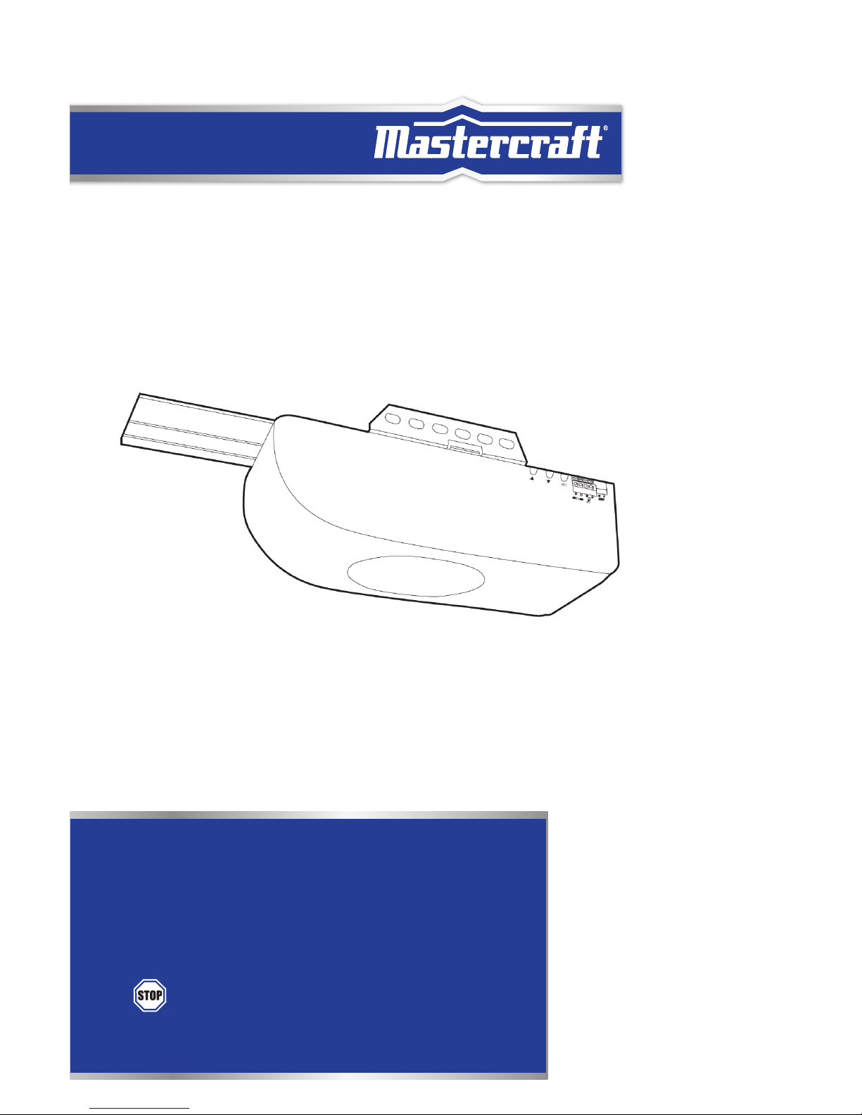
CHAIN DRIVE GARAGE DOOR OPENER
INSTRUCTION
MANUAL
IMPORTANT:
• Please read this manual and enclosed safety materials carefully!
• Safety infrared sensor MUST BE INSTALLED and aligned properly.
• Periodically testing the opener is required to ensure safe operation.
• Save this manual for future reference.
• This equipment meets or exceeds all federal, provincial and UL325
safety requirements.
•
DO NOT RETURN this to the store
• Please call: 1-800-689-9928.
model no. 046-0265-2
Page 2

headline bars
Page 3

3
TABLE OF CONTENTS
TABLE OF CONTENTS
Introduction 5
Pre-Installation Checklist 6
What is Included 7-9
Important Instructions 10-11
Assemble The T-Rail 12-17
Install The Header Bracket 18-21
Hang The Opener 22-23
Install The Door Bracket 24-25
Install The Door Arms 26-28
Install The Wall Console 29-30
Connect The Opener To Power 31-32
Install Safety Beam Sensor 33-37
Programming Guide 38-41
Safety Tests 42
Operation 43-46
Maintenance 47-48
Troubleshooting 49-51
Optional: Programming 52
Accessories 53
FCC 54
Limited Warranty 55
NOTE:
• If any parts are missing or damaged, or if you have any questions, please call our toll-free helpline at
1-800-689-9928.
Page 4

headline bars
headline bars
model no. 046-0265-2 | contact us 1-800-689-9928
TABLE OF CONTENTS
BLANK PAGE (ON PURPOSE)
Page 5

5
INTRODUCTION
INTRODUCTION
Congratulations on purchasing the Mastercraft® Chain Drive Garage Door Opener – a garage
door opener with many innovative features. Features include: extremely quiet operation with
DC motor; automatic force adjustment so the door can be closed with just the right amount
of force, not overpowered; and a state-of-the-art safety reversal system that protects your
family and property near the door.
Important Safety Information
The documentation provided with your opener has been carefully designed and organized
to make the assembly, operation and continued maintenance of your product as easy and
safe as possible. Assuring an extended life of this product is based upon the installation,
operation, maintenance and testing in strict accordance with the instructions and warnings
stated in this manual. Read and follow all guidelines and operating instructions before using
this product. Store the manual in a safe and easily-accessible location for future use.
Safety Symbol Overview
WARNING
This type of warning symbol is used to indicate possible mechanical hazards that may cause
serious injuries or death.
CAUTION
This type of warning symbol is used to indicate the possibility of damage to the garage door
or opener.
Page 6
headline bars
PRE-INSTALLATION CHECKLIST
model no. 046-0265-2 | contact us 1-800-689-9928
6
PRE-INSTALLATION CHECKLIST
Check the following items before assembling the opener:
• Identify the door type: sectional door or one-piece jamb door.
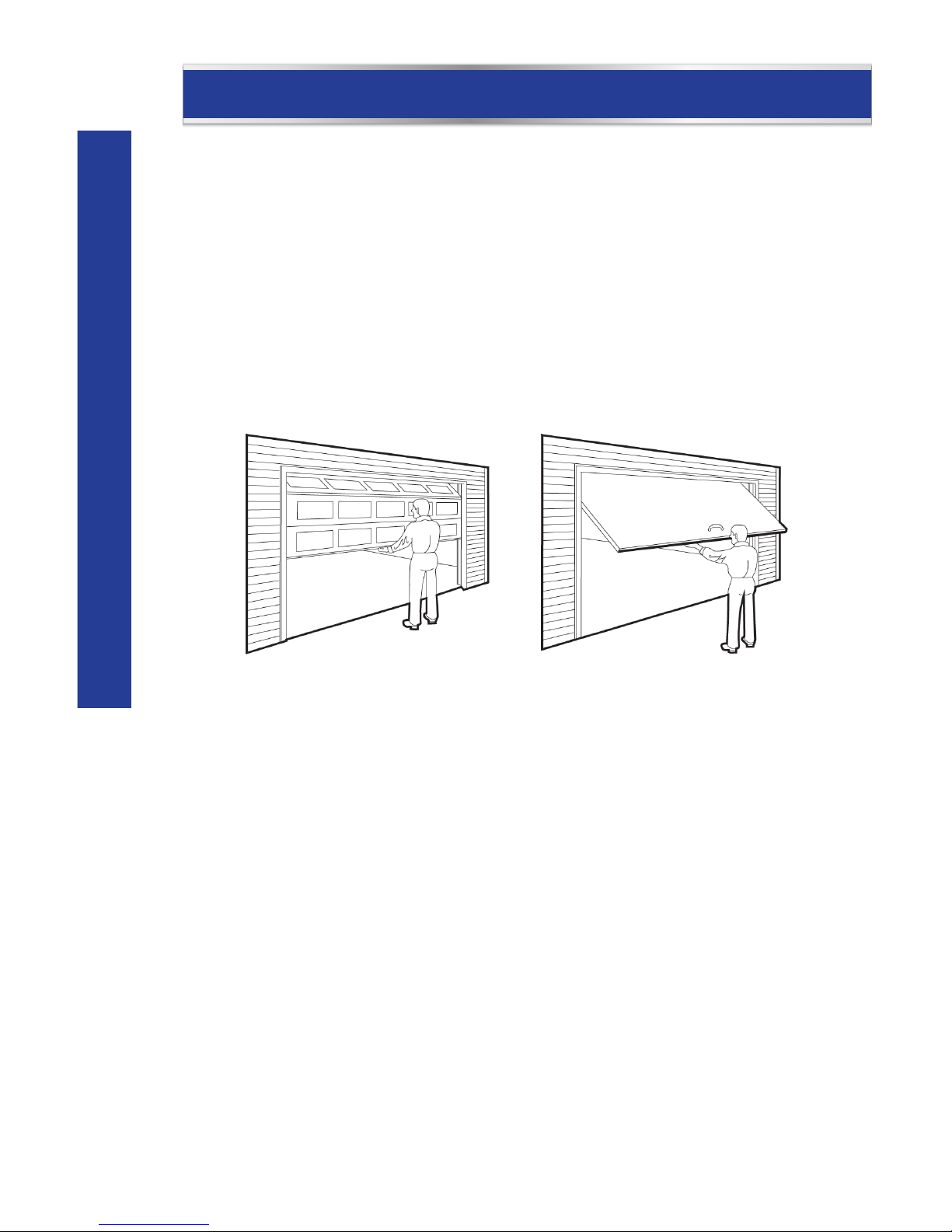
• Ensure your garage door is balanced and is not sticking or binding.
• Here is how to check the door balance:
◊ From outside the garage, slowly open the door all the way and close it all the way –
DOOR SHOULD NOT BIND OR RUB.
◊ Raise the door halfway up – DOOR SHOULD STAY IN PLACE, SUPPORTED ENTIRELY BY
ITS SPRING.
• IMPORTANT: IF THE GARAGE DOOR FAILS EITHER OF THESE TESTS, HAVE A QUALIFIED
GARAGE DOOR PROFESSIONAL ADJUST OR REPAIR THE DOOR.
• If the garage door is lightweight (made with frame and skin, not solid), it must be braced
or reinforced before installing the opener (including the door frame). Check with a qualified
service professional for a door reinforcement kit.
• If you do not have an access door in addition to the garage door, you should install an
emergency key release kit.
• If your door is more than 7' (2.1 m) high, you will need a rail extension kit (sold separately).
• With the garage door closed, check alignment of door and garage floor. The gap, if any,
should be no more than 1/4" (6 mm). If the gap is larger than this, repair floor or door
before installing opener.
Sectional Door
One-piece Jamb Door
Page 7
7
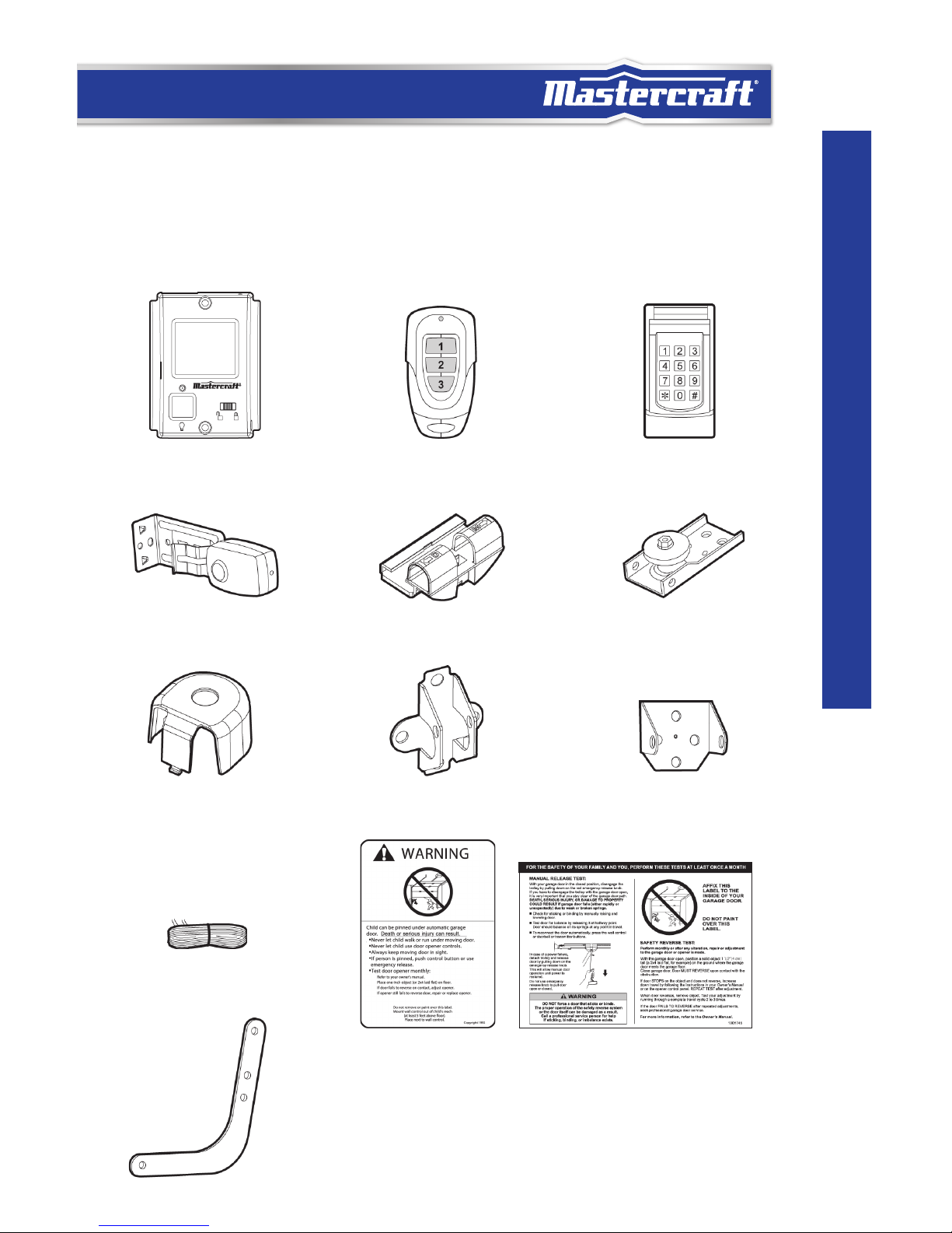
WHAT IS INCLUDED
Safety Beam Unit
Keyless Entry
WHAT IS INCLUDED
The garage door opener and all accessories are packaged in one carton.
Note that accessories will depend on the model you purchased. If anything is missing,
carefully check the packing material.
Bell Wire
Curved Arm
Door Bracket Head Bracket
Keychain Remote
Pulley Assembly
Sprocket Cover
Trolley
Wall Console
Safety Labels
Page 8
8
headline bars
model no. 046-0265-2 | contact us 1-800-689-9928
WHAT IS INCLUDED
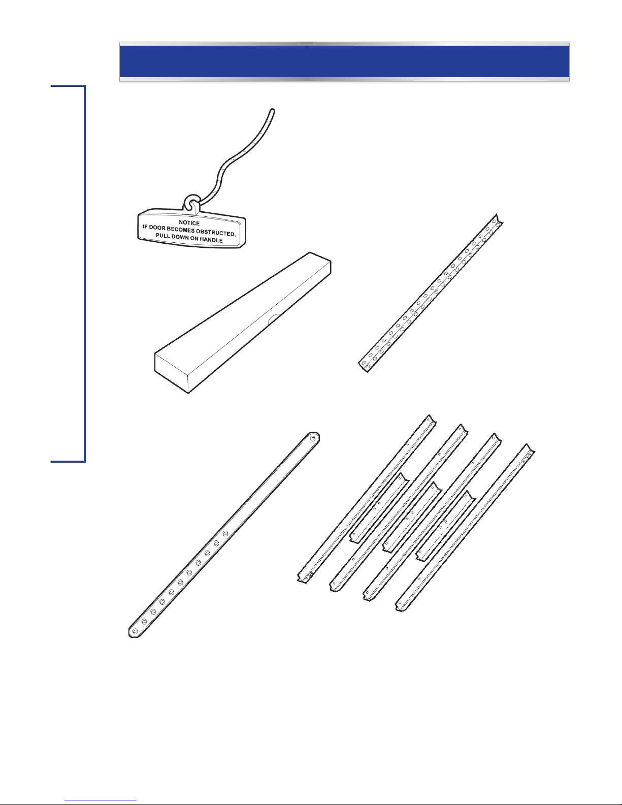
Straight Arm Rail Sections
Chain and Cable
Assembly
Hanging
Bracket
Emergency Release
Rope
Page 9
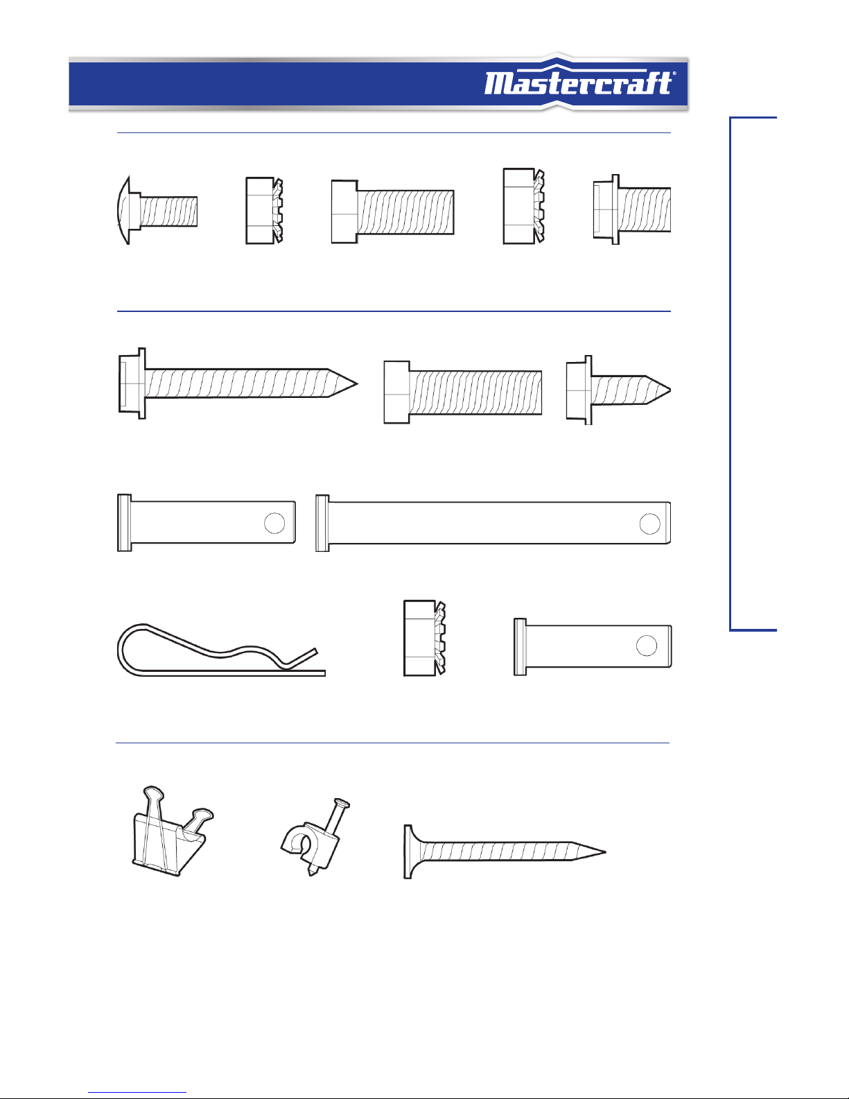
9
WHAT IS INCLUDED
C2 x 4
Wire Clip
C3 x 20
Wire Holder
C5 x 4
Wood Screw
BAG C
BAG B
B6 x 3
Hitch Pin
B8 x 4
Locknut
B9 x 1
Clevis Pin
B1 x 4
Lag Screw
B2 x 4
Bolt
B3 x 2
Self-tapping Screw
B4 x 1
Clevis Pin
B5 x 1
Clevis Pin
BAG A
A1 x 12
Carriage Bolt
A2 x 12
Locknut
A3 x 2
Bolt
A4 x 3
Locknut
A5 x 3
Flange Bolt
Page 10

headline bars
headline bars
IMPORTANT INSTRUCTIONS
model no. 046-0265-2 | contact us 1-800-689-9928
10
IMPORTANT INSTRUCTIONS
WARNING
To reduce the risk of severe injury or death:
1. READ AND FOLLOW ALL INSTALLATION INSTRUCTIONS.
2. Check with the door manufacturer to determine if additional reinforcement is required to
support the door prior to installation of the garage door opener.
3. Install garage door opener only on a properly balanced garage door. An improperly
balanced door could cause serious injury. Have a qualified service professional make
repairs to garage door cables, spring assemblies and other hardware before installing
the opener.
4. Remove all ropes and disable all locks connected to the garage door before installing
opener.
5. Mount the emergency release handle 6' (1.8 m) above floor.
6. Do not connect the opener to source of power until this manual instructs you to do so.
7. Locate the wall console or wall console:
I Within sight of the garage door.
II Out of reach of children at minimum height of 5' (1.5 m).
III Away from all moving parts of the door.
8. Place entrapment warning label on wall next to garage door wall control.
9. Install the Emergency Release Handle on the emergency release rope.
10. Place manual release/safety reverse test label in plain view on inside of garage door.
11. Upon completion of the installation, the door must reverse when it comes in contact with
a 1 1/2" (3.8 cm) high object on the floor (or a 2x4 laid flat at the centre of the door) and
when the infrared safety beam is blocked.
Page 11
11
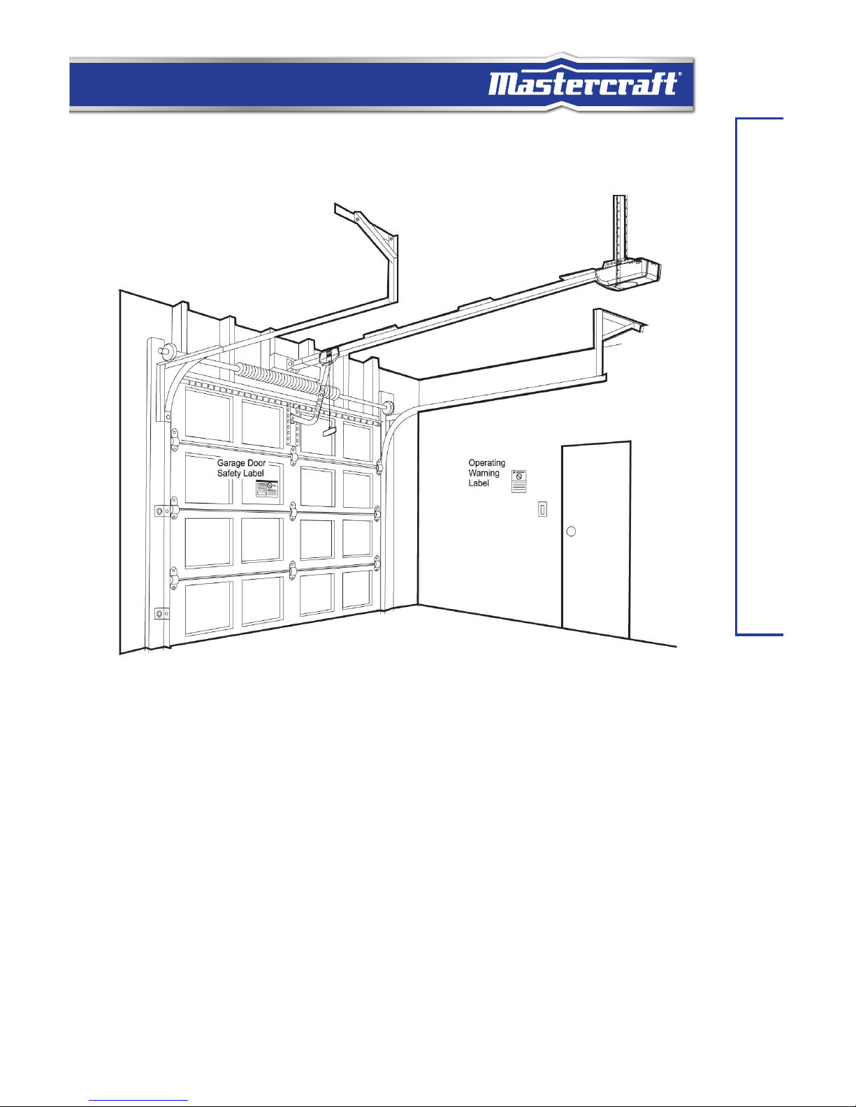
IMPORTANT INSTRUCTIONS
An overall view of a completed garage door opener system installed on a sectional door. The
arrangement is similar for a one-piece jamb door (except for differences described later in
this manual).
Page 12
headline bars
headline bars
ASSEMBLE THE T-RAIL
model no. 046-0265-2 | contact us 1-800-689-9928
12
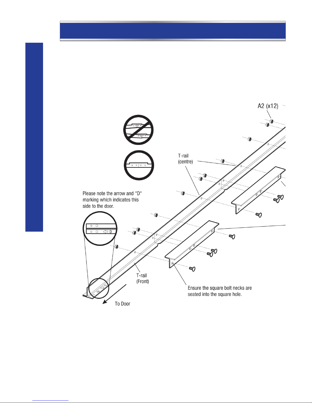
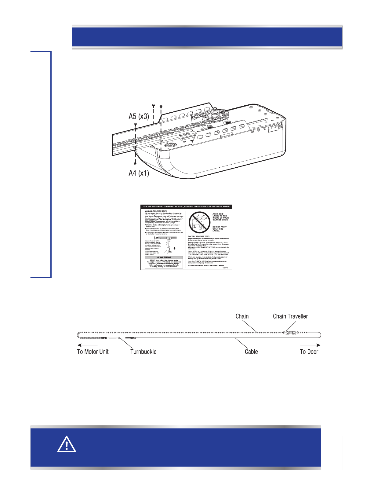
ASSEMBLE THE T-RAIL
Connect the T-Rail Sections
Align the 4 T-Rail sections on the floor. Connect these rails together with the rail couplers as
shown.
All rail pieces must be aligned properly.
Page 13
13
ASSEMBLE THE T-RAIL
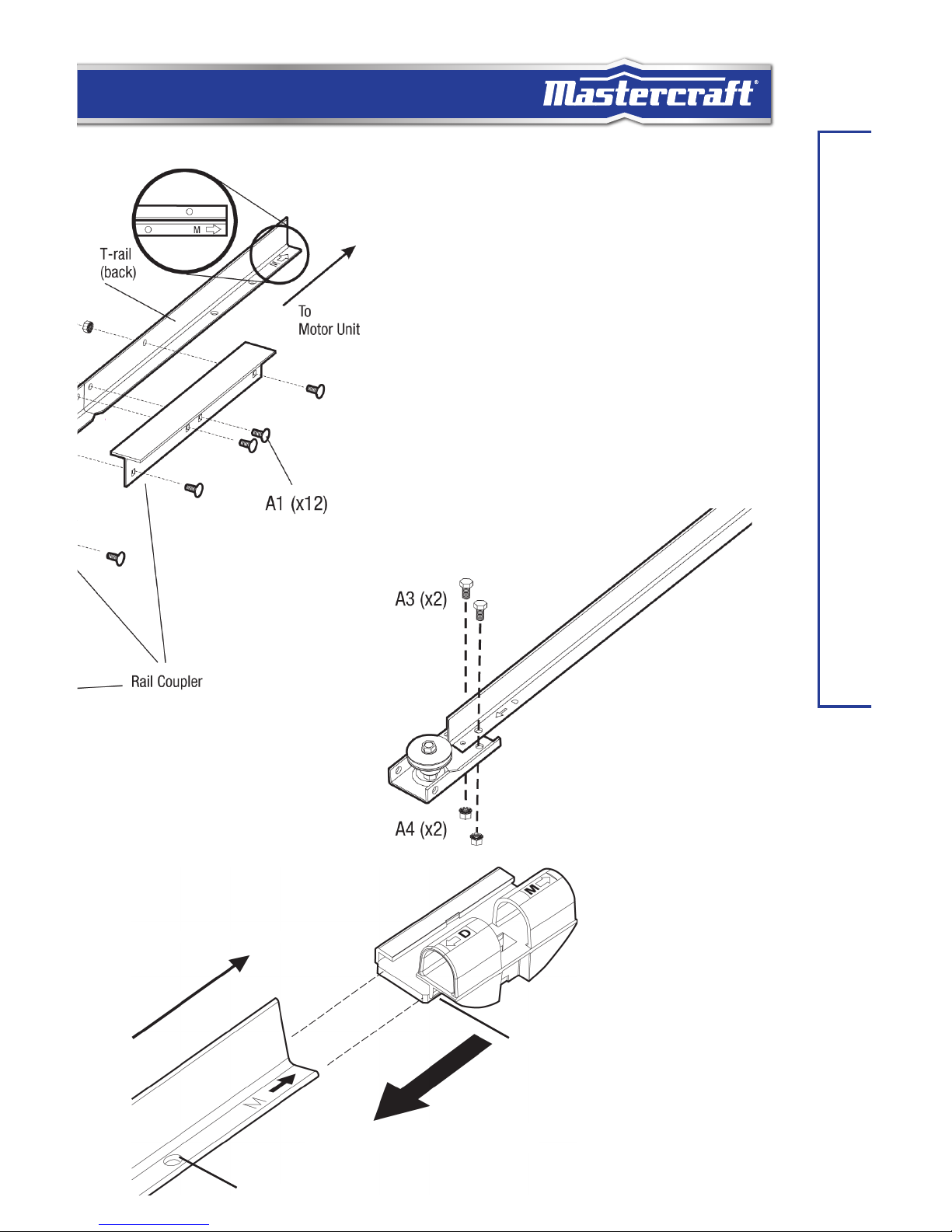
Attach the Pulley Bracket
Attach the pulley bracket assembly to the end of the
front rail with 2 nuts and bolts.
Align the pulley bracket and rail.
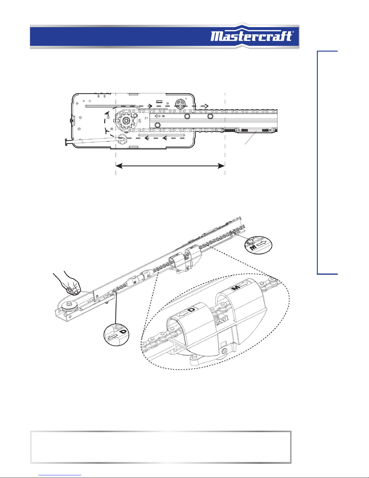
Install the Trolley
Please note the arrow and “M” marking which
indicates this side to the motor unit.
Ensure this side of the trolley is on the
stop bolt hole side of the rail.
Slide the trolley from the back of the
T-rail assembly.
Stop Bolt Hole.
To Motor Unit (Back)
Page 14
14
headline bars
model no. 046-0265-2 | contact us 1-800-689-9928
ASSEMBLE THE T-RAIL
Attach the T-Rail to the Opener
Raise the pulley end of the rail so the rail can sit on the motor unit properly. Attach the rail
to the motor unit by tightening 2 screws. Insert a bolt to the stop bolt hole and secure it with
nut.
Apply the Safety Label
Prepare the Chain
Lay down the chain on the floor, as shown. Do not twist the chain or cable.
CAUTION
• Use only the specified bolts to attach the T-rail to the opener. Any other bolts will cause serious damage
to the opener.
Page 15
15
ASSEMBLE THE T-RAIL
Align the Chain on the Sprocket
Start aligning the chain by placing the turnbuckle 10" (25 cm) from the sprocket. Wrap the
chain around the sprocket. The sprocket teeth must engage the chain as shown.
Place the Cable on the Pulley
Place the cable around the pulley at the end of the rail.
Start from Here
10" (25 cm)
NOTE:
• Ensure chain/cable passes through the trolley guides. Insert the trolley guides into the chain traveller until
you hear a click when the chain traveller is completely seated into the trolley.
Page 16
Do not rotateDo not rotate
16
headline bars
model no. 046-0265-2 | contact us 1-800-689-9928
ASSEMBLE THE T-RAIL
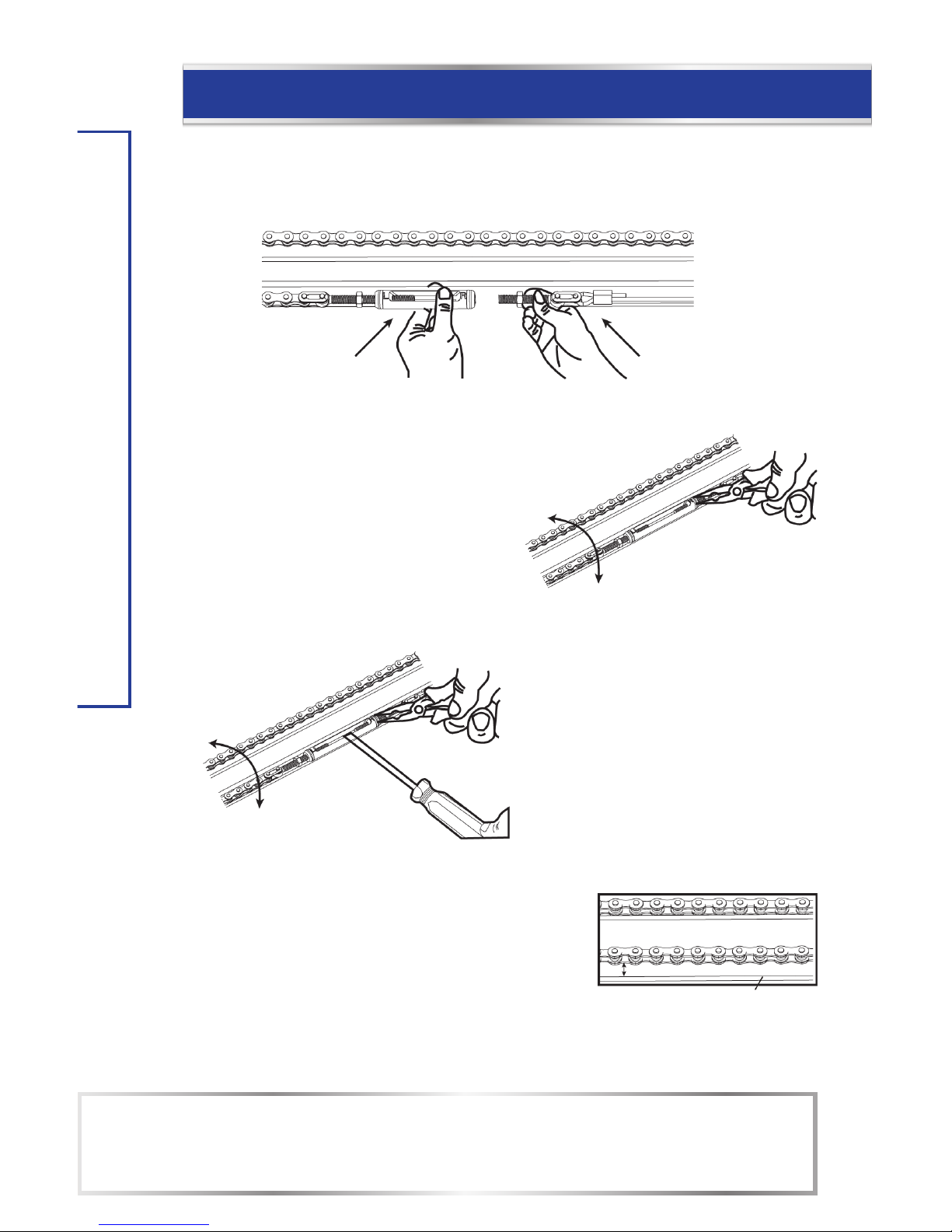
Tighten the Chain and Cable
Connect the 2 ends of the chain assembly together at the turnbuckle.
To connect the turnbuckle and threaded
shaft, hand tighten the turnbuckle by rotating
the turnbuckle only.
Do not rotate the threaded shaft to avoid
twisting the cable.
Twist the turnbuckle to tighten the chain tension until
the chain is 1/3" (8 mm) above the base of the T-rail.
To avoid twisting the cable, use pliers to
hold the threaded shaft while tightening
the turnbuckle with a flat screwdriver.
NOTE:
• After completing the installation, you may notice some chain drop with the door fully closed. The chain
should return to the position as shown when the door is open.
• Too much or too little tension will cause excessive noise.
Locknuts
Tighten
Locknuts Loosen
Tighten the locknuts
once the desired
tension is achieved.
Chain Loosen
Chain Tighten
Base of Rail
1/3" (8 mm)
Page 17
17
ASSEMBLE THE T-RAIL
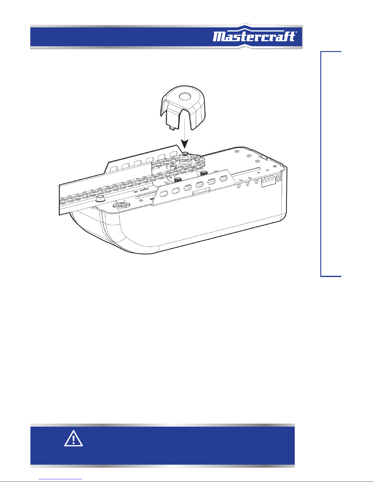
Attaching the Sprocket Cover
Squeeze the cover slightly and insert the 2 tabs on the cover in the slots on the motor unit.
WARNING
• Always keep hand clear of sprocket and chain while operating opener.
• Securely attach sprocket cover before operating.
Page 18

headline bars
headline bars
INSTALL THE HEADER BRACKET
model no. 046-0265-2 | contact us 1-800-689-9928
18
INSTALL THE HEADER BRACKET
Mark the Door Centerline
Close the door from inside the garage and mark the vertical centreline of the door on the wall
and the top door panel.
Sectional Door
One-piece Jamb Door
WARNING
• Header bracket must be secured to structural supports. If appropriate support does not exist, install a
new support using 2x4 board on drywall or between 2 studs with lag screws (not included). DO NOT
install header bracket over drywall.
• Concrete anchors must be used if mounting header bracket or 2x4 into masonry.
• Always call a trained door systems technician if garage door binds, sticks, or is out of balance. An
unbalanced garage door might not reverse when required.
Page 19

19
INSTALL THE HEADER BRACKET
Attach a 2x4 (if necessary)
If the calculated header bracket is above the door header, attach a 2x4 between two studs to
install the header bracket.
Door header
Use lag screws (not included) to attach
the 2x4.
Mark Above the Highest Point of Travel
Mark a spot on the
centreline of the garage
door, 1 1/4" (3 cm) above
the highest point of travel
of the garage door.
Mark a spot on the
centreline of the
garage door, 7”
(18 cm) above the
highest point of travel
of the garage door.
One-Piece Jamb Door
Highest point of travel
1 1/4" (3 cm) above
highest point of travel.
Sectional Door
7" (18 cm)
1 1/4" (3 cm)
Page 20

20
headline bars
model no. 046-0265-2 | contact us 1-800-689-9928
INSTALL THE HEADER BRACKET
Attach the Header Bracket
Place the bottom edge of the bracket on the line marked above the highest point of travel.
Note the orientation of the header bracket. Do not mount it upside down.
Ceiling Installation
The header bracket may be mounted to the
ceiling if there is minimal clearance above the
door. If so, extend the centreline to the ceiling.
The back edge of the bracket must not be
further than 5" (12.7 cm) from the header wall.
1 1/4" (3 cm) Above Sectional Door/
7" (18 cm) Above One-piece Jamb Door
Highest Point of Travel
Mark the 2 holes with
a pencil.
Drill two 3/16" (5 mm) pilot holes.
Attach the header bracket with
2 lag screws provided.
5" (12.7 cm)
Page 21

21
INSTALL THE HEADER BRACKET
Connect the T-Rail to the Header Bracket
Position The Opener
Position the pulley bracket against the header bracket.
Position the opener on the floor
with packaging material as
protective base.
Align the bracket holes and join
with a clevis pin and hitch pin as
shown.
Page 22

headline bars
headline bars
HANG THE OPENER
model no. 046-0265-2 | contact us 1-800-689-9928
22
HANG THE OPENER
Raise the Opener
Raise the opener onto a stepladder. Use extra spacers on top of the ladder if the ladder is not
tall enough.
Carefully raise the door to the fully open position. Be sure the door is clear from the rail or
any other part of the opener.
Place a 2x4 laid flat on the top section beneath the T-rail.
Sectional Door
laid flat
Carefully raise the door to the fully open position so that it is parallel to the floor.
Position the opener so that top of the opener head is level with the top of the opened door.
One-piece Jamb Door
Page 23

23
HANG THE OPENER
Attach the Hanging Brackets
Hanging brackets should be angled to provide rigid support. Measure the distance from the
motor unit to the structural support. Cut and bend the hanging brackets as required.
For an “open-seam” garage, attach the hanging brackets directly to the joists with 2 lag screws.
Bracket (not included)
Bolts and Nuts (not included)
On a finished ceiling, attach a sturdy metal bracket (not included) to structural supports before installing
the opener.
Attach the Opener to the Hanging Brackets
Attach the opener to the hanging brackets with
two bolts and nuts.
Ensure the T-rail is centred over the door. Remove
the 2x4.
WARNING
• To avoid possible serious injury from a falling garage door opener, fasten it securely
to structural supports of the garage. Concrete anchors must be used if installing any
brackets into masonry.
Page 24

Bolt 5/16 x 2" (8 x 50 mm)
(not included)
headline bars
headline bars
INSTALL THE DOOR BRACKET
model no. 046-0265-2 | contact us 1-800-689-9928
24
INSTALL THE DOOR BRACKET
Door arm connects directly
to vertical reinforcement
Top of Door
Door Bracket
Location
Hardware
(not included)
Sectional Metal Doors
Align the door bracket on the centreline 2 to 4" (5 to 10 cm)
below the top edge of the door, or directly below any door
structural support.
Drill two 3/16" (5 mm) pilot holes. Use 2 self-threading
screws to secure the door bracket.
Sectional Wood Doors
For wood doors, drill 5/16" (8 mm) holes through the door
and secure bracket with 5/16 x 2" (8 x 50 mm) carriage
bolts, lock washers and nuts (not included).
Page 25

25
INSTALL THE DOOR BRACKET
One-Piece Metal Doors
Drill two 3/16" (5 mm) pilot holes. Use 2 self-threading screws to
secure the door bracket.
One-Piece Wood Doors
For wood doors, drill 5/16" (8 mm) holes through the door and secure
bracket with 5/16 x 2" (8 x 50 mm) carriage bolts, lock washers and nuts
(not included).
Centre the door bracket
on the top of the door.
CAUTION
• Lightweight garage doors are not designed for use with garage door opener must be
equipped with a door reinforcement kit. Check with the garage door manufacturer for
more information. Many door reinforcement kits provide for direct attachment of the clevis
pin and door arm. In this case, you will not need the door bracket, proceed to “Install the
Door Arms” section.
Bolt 5/16 x 2" (8 x 50 mm)
(not included)
Page 26

headline bars
headline bars
INSTALL THE DOOR ARMS
model no. 046-0265-2 | contact us 1-800-689-9928
26
INSTALL THE DOOR ARMS
Attach Emergency Release Rope
Thread the red rope through the hole in the trolley release handle and tie an over-hand knot.
Leave the trolley release lever in the released position until further testing is completed.
Connect the Door Arm to Door Bracket
Sectional Door
Connect the curved door arm to the door
bracket with clevis pin and hitch pin.
Engaged Released
One-piece Jamb Door
Connect the straight arm to the door
bracket with clevis pin and hitch pin.
Page 27

27
INSTALL THE DOOR ARMS
Connect the Door Arm to the Trolley
Sectional Door
Connect the straight door arm to the trolley with clevis pin and hitch pin.
One-piece Jamb Door
Connect the curved door arm to the trolley with clevis pin and hitch pin.
WARNING
• Use extreme care when pulling release handle. DO NOT use handle to pull door open or
closed.
• Never use emergency release handle unless garage doorway is clear of persons and
obstructions.
NOTE:
• Emergency release handle should hang 6' (1.8 m) above floor. Adjust rope length if it is necessary.
Page 28
headline bars
28
headline bars
model no. 046-0265-2 | contact us 1-800-689-9928
INSTALL THE DOOR ARMS
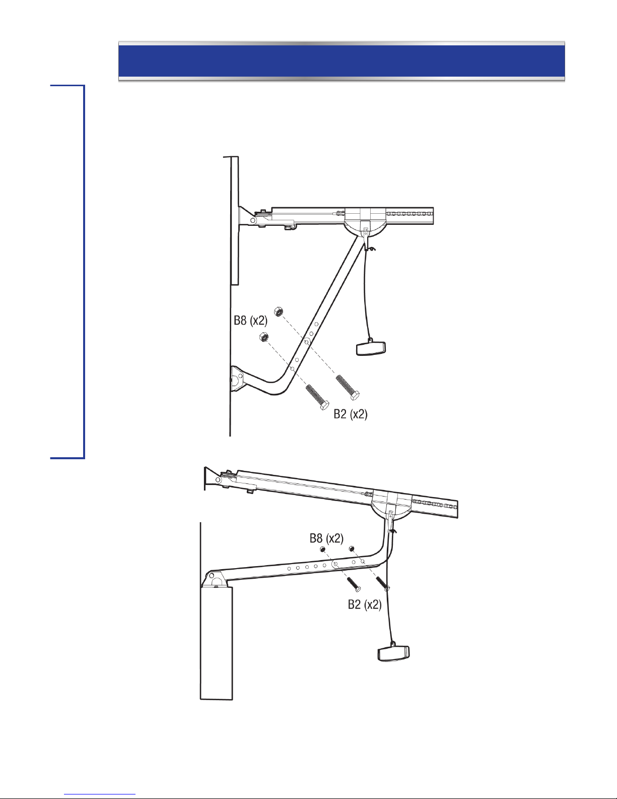
Connect the Door Arms Together
Bring two arms together. Find two pairs of holes that line up and join 2 arms with bolts and
nuts. Select holes as far apart as possible to increase door arm rigidity.
Sectional Door
One-piece Jamb Door
Page 29

29
INSTALL THE WALL CONSOLE
INSTALL THE WALL CONSOLE
Place the wall button or wall console at least 5’ (1.5 m) above the finished floor or the
topmost step.
5' (1.5 m)
Connect the bell wires to the 2 terminal
screws. Wires are not polarity sensitive.
Secure the wall console with two screws.
WARNING
• Wall console must be installed within sight of the garage door, out of reach to children at a
minimum height of 5' (1.5 m) and away from all moving parts of door.
• Be sure power is not connected before installing the wall console.
• Wall console should only be activated when door can be seen clearly, is properly adjusted
and there are no obstructions to door travel.
• Always keep garage door in sight until completely closed. Never permit anyone to cross
path of closing garage door.
Page 30
headline bars
30
headline bars
model no. 046-0265-2 | contact us 1-800-689-9928
INSTALL THE WALL CONSOLE
Mount the user safety instruction label next to the wall console.
Route the wire up the wall and across the ceiling to the opener with wire holders.
Connect the wires to the terminals .
Wires are not polarity sensitive (either wire to either terminal).
White Black
Page 31

31
CONNECT THE OPENER TO POWER
CONNECT THE OPENER TO POWER
Connect AC Power
Plug motor unit into grounded outlet. If a grounded outlet
is not available, contact a qualified electrician to install
a proper outlet. DO NOT ACTIVATE THE OPENER UNTIL
INSTRUCTED.
Permanent Wiring/Remove Cover
Be sure the power cord is unplugged. Remove the screws
from the cover of the opener.
Permanent Wiring -
Remove the Power Cord
WARNING
If permanent wiring is required by your local code, have a licensed electrical contractor follow
the procedures outlined in this manual. Disconnect power to the circuit before removing
cover.
• Be sure power is not connected to the opener and disconnect power to circuit before
removing cover to establish permanent wiring connection.
• Garage door installation and wiring must be in compliance with all local electrical and
building codes.
• Never use an extension cord, 2-wire adaptor, or change plug in any way to make it fit
outlet. Be sure the opener is grounded.
• The opener has a grounded type plug for your protection and only fits into a grounding
type outlet. Do not change the plug in any way.
Page 32

Remove the bushing with pliers
headline bars
32
headline bars
model no. 046-0265-2 | contact us 1-800-689-9928
CONNECT THE OPENER TO POWER
Permanent Wiring/Hardwire the Opener
Green – Ground
White – Neutral
Black – Hot
Connect conduit wiring to opener wiring with wire nuts (not included). Install the bottom
cover and screws.
Permanent Wiring/Remove the Bushing
Be sure the power cord is unplugged. Cut the
cord about 6" (15 cm) above the bushing.
Page 33
33
INSTALL SAFETY BEAM SENSOR
INSTALL SAFETY BEAM SENSOR
Important Information: The safety beam sensor can detect obstacles in the path of its
invisible beam. When the beam is obstructed while the door is closing, the door will stop
immediately, reverse to the fully open position and the opener lights will flash. It is important
to ensure the invisible infrared is unobstructed by any part of the garage door, tracks, other
hardware or objects near the garage door.
Identify the Transmitter and
the Receiver
The unit with the red LED is the
transmitting sensor. The unit with
the blue LED is the receiving sensor.
Avoid sunlight shining directly into the
receiving sensor.
WARNING
• Be sure power is not connected to the garage door opener while installing the safety beam
sensor.
• The safety beam sensor must be installed and aligned properly.
• This safety device must not be disabled.
• The safety infrared sensor must not be installed higher than 6” (15 cm) above the garage
floor.
NOTE:
• Receiving sensor is labelled “Receive” on the wire.
Page 34

34
headline bars
model no. 046-0265-2 | contact us 1-800-689-9928
INSTALL SAFETY BEAM SENSOR
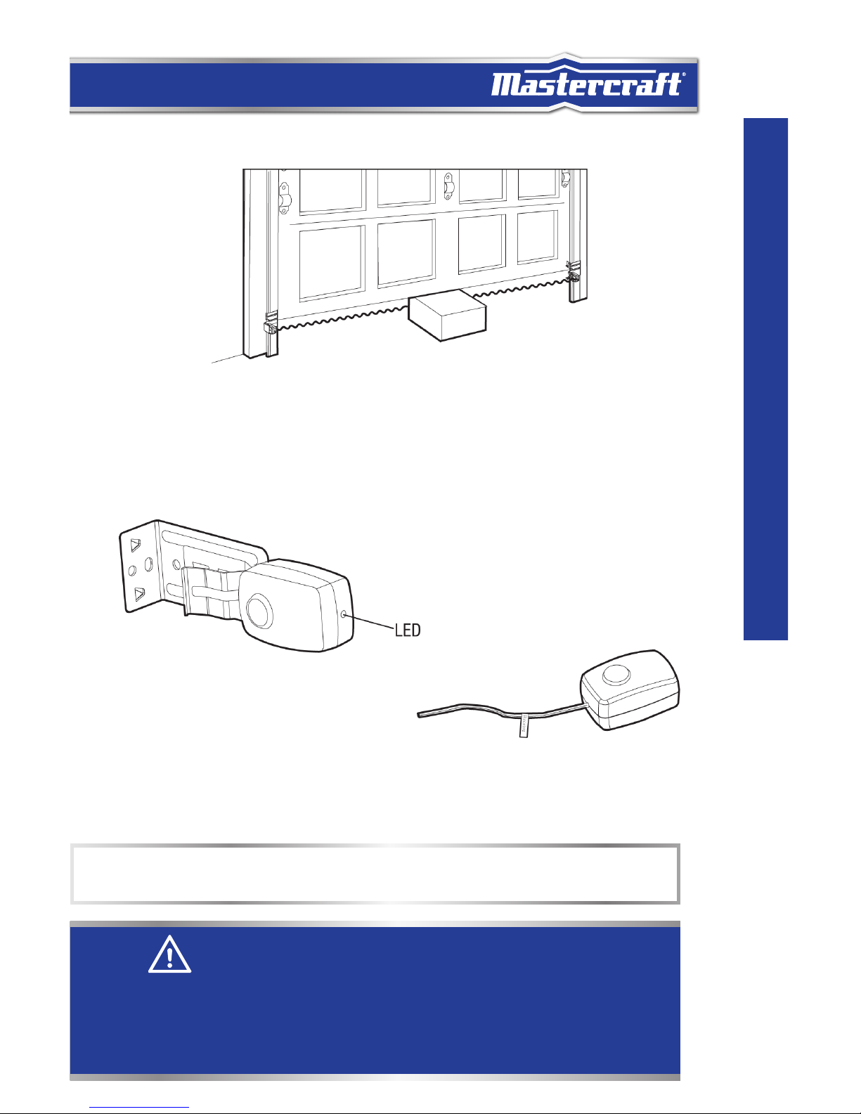
Mounting the Sensor on the Door Track
Clip the mounting bracket onto the garage door track. Ensure the sensor is mounted between
4" (10 cm) and 6" (15 cm) above the ground. Follow the same procedure to install the sensor
on the other track ensuring the sensors are facing each other.
4 to 6" (10 to 15 cm)
Mounting the Sensor on the Wall (Optional)
For wall mounting, use a wooden block to increase depth until there is enough clearance for
the sensor beam to be unobstructed.
Mounting the Sensor on the Floor (Optional)
For floor mounting, use a wooden block to elevate the sensor brackets, if necessary. Ensure
the sensor is no higher than 6” (15 cm) above floor. Fasten the screws to the floor with
concrete anchors (not included).
Wood Block
Page 35

35
INSTALL SAFETY BEAM SENSOR
Route and Secure the Sensor Wires
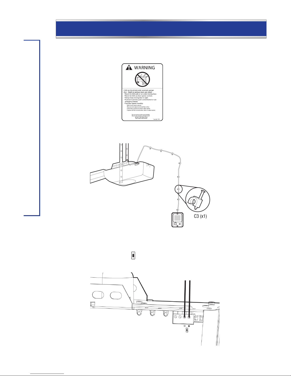
Run the wires up the wall, then over to the centre of the door. Secure the wires to the wall
with wire holders. Run the wires along the top of the T-rail and secure them with 4 wire clips
provided.
Connect the Wires to the Opener
Twist like-coloured wires together. Connect the wires to the safety sensor terminals .
Wires are not polarity sensitivity (either wire to either terminal).
Black White
NOTE:
Remove the spring bracket from the mounting bracket if installing to the wall or floor.
1. Slide the sensor from the
mounting bracket.
2. Slide the spring bracket
from the mounting bracket.
3. Re-install and secure the
sensor to the mounting
bracket.
Page 36

36
headline bars
model no. 046-0265-2 | contact us 1-800-689-9928
INSTALL SAFETY BEAM SENSOR
Align the sensors
Check the Safety Beam Sensor LED
Plug in the opener. The receiving sensor indicator's blue LED should
glow steadily if the wiring and alignment are correct. The transmitting
sensor indicator's red LED will glow steadily regardless of alignment
or obstruction.
Align the Safety Beam Sensor
If the receiver LED is off, dim, or flickering (while the invisible light beam path is not
obstructed), alignment is required.
If the blue LED is flashing or off, slide the mounting bracket up or down on the track until
the blue LED is steadily on. The tab for the sensor can also be adjusted by a slight bend if
needed for alignment.
When properly adjusted both the red and blue LED will be steadily on.
Receiving Sensor (Blue LED)
Blue Light:
On – Beam Aligned. No Obstructions.
Off – Beam Not Aligned Or Obstruction – Sensors Need Alignment.
Dim/Flickering – Sensors Need Alignment.
Transmitting
Sensor (Red LED)
Red Light:
On – Power On.
Off – Power Off.
NOTE:
After two minutes the sensors will go into sleep mode and the red and blue LED will flash
every 10 seconds. When the door is closing, the sensors will return to normal operation
with red and blue LED steadily on.
Page 37

37
INSTALL SAFETY BEAM SENSOR
NOTE:
• Be sure to stay out of the beam’s path while aligning.
• The LED in the safety beam sensors will flash in every 10 seconds during standby mode.
NOTE:
If the transmitting sensor LED does not glow steadily, check the following:
I. Power to the opener is connected.
II. A short in the white or white/red wires (from wire holders or at the openers terminals).
III. Incorrect wiring between sensors and opener.
IV. A broken wire.
If the transmitting sensor LED glows steadily but the receiving sensor LED doesn’t glow:
I. Check alignment.
II. Check for an open wire to the receiving sensor.
III. Check for dirt on lens, or sun shining into lens.
Testing with Obstruction
With the sensors properly aligned, place
an obstacle in the path of the beam. The
transmitting sensor's red LED should be
on, the receiving sensor's blue LED should
be off. Remove the obstacle, both LEDs
should be on steadily.
Page 38

headline bars
headline bars
PROGRAMMING GUIDE
model no. 046-0265-2 | contact us 1-800-689-9928
38
PROGRAMMING GUIDE
While programming, the p and q buttons can be used to move the door as needed.
A. Set Up Travel Limit and Open/Close Force
1. Connect the opener to an approved
power source. The dot in the LED
display stays on.
2. Press and hold [SET] button for 5
seconds until the LED display shows
the number “1”. Release the [SET]
button.
3. Press the p button until the door is in
fully open position.
4. Press the [SET] button to confirm the
door position.
SET DOOR TRAVEL
LIMIT (OPEN/CLOSE)
5. The LED display will show the number
“2”.
6. Press the q button until the door is in
fully closed position.
7. Press the [SET] button again to
confirm.
8. The LED light will flash 3 times when
the travel limit settings are completed.
SET DOOR TRAVEL
LIMIT (CLOSE/OPEN)
9. The LED display will show the number
“3”.
10. Press the wall button to open the
garage door to its fully open position.
11. The LED light will flash 3 times.
LEARN DOOR FORCE
(OPEN/CLOSE)
12. The LED display will show the number
“4”.
13. Press the wall button again to close
the garage door to its fully closed
position.
14. The LED display will turn off.
LEARN DOOR FORCE
(CLOSE/OPEN)
LED
Page 39

39
PROGRAMMING GUIDE
B. Changing Force Adjustment
1. Press and hold the [SET] button for 10
seconds. When the LED display shows
“F”, release the [SET]button.
2. The LED display will show “0”.
SET FORCE LEVEL
3. Press the p or q button to set the
force 0, 1, 2 or 3.
0 is the default force level.
3 is maximum force level.
4. Press the [SET] button again to
confirm the force at the desired level.
C. Programming Remote Control
1. Press the [SET] button for one second.
The LED display will show the letter
“P”.
LEARN WIRELESS
CONTROL
2. Program a Remote:
Within 30 seconds, press any button
on the remote that you would like to
program to the opener.
3. Once the button on the remote is
programmed, the LED display will turn
off and emit one beep indicating the
programming has been successful.
LEARN WIRELESS
CONTROL
Page 40

40
headline bars
model no. 046-0265-2 | contact us 1-800-689-9928
PROGRAMMING GUIDE
D. Keypad Initial Setup
The factory default PIN is 0 0 0 0. It will be used during the keypad initial setup.
After you set your own PIN, you will need to use your current PIN instead of 0 0 0 0 in below
steps.
1. FOR SINGLE DOOR
A. Enter 0 0 0 0 and *.
B. Enter the new PIN (2 to 8 digit password) and *.
C. Enter your PIN again and *.
If the new PIN codes are the same, the keypad will beep 3 times.
If not, it will emit a long beep.
D. Press the [SET] Button on the opener
E. Within 30 sec. enter your PIN on the keypad and press #
F. Now enter your PIN and # to open/close the garage door.
2. FOR MULTIPLE DOORS:
G. Enter 0 0 0 0 * 9 # to enable multiple door mode.
(0 0 0 0 # 0 # to disable and back to single door)
Will beep 2 times to confirm the multiple-door operating mode is enabled.
A. Enter 0 0 0 0 and *.
B. Enter the new PIN and press *.
C. Enter your PIN again and press *.
D. Press the [SET] Button on the opener
E. Within 30 sec. enter your PIN on the keypad and press #1
F. Now enter your PIN and #1 to open/close the garage door.
Repeat step 6 and 7 to program additional doors:
2nd door: PIN #2, ex. 1 2 3 4 #2
3rd door: PIN #3, ex. 1 2 3 4 #3
NOTE:
• To erase any unwanted remote control, first erase all remotes.
Page 41

41
PROGRAMMING GUIDE
E. Erasing all the Remote Controls from Opener
1. Press the [SET] button for 15 seconds.
When the LED display flashes “E”,
release the [SET]button.
2. Press the [SET] button again to
confirm erase all the programmed
remotes.
3. The dot in the LED display stays
on indicating the erasing has been
successful.
ERASE WIRELESS
CONTROL
(FLASHING)
Page 42

headline bars
SAFETY TESTS
model no. 046-0265-2 | contact us 1-800-689-9928
42
WARNING
• Without a properly installed safety reversing sensor, persons (particularly small children) could be
seriously injured or killed by a closing garage door.
SAFETY TESTS
Test Safety Reversal System
With the door fully open, place a 1 1/2" (3.8 cm) board (or 2x4 laid flat) on the floor, centred
under the garage door. Close the door by
pressing the button on the wall console.
After making contact with the board, the
door should stop then reverse to a fully open
position.
If the door fails to reverse:
• If the door stops on the obstruction, re-
adjust the down travel limit as it is not
travelling far enough in the down direction.
• Repeat the test until the door reverses upon striking the obstruction.
Test Safety Beam Sensor System
To test the safety beam sensor system, open the door to the fully open position.
1. Place an obstacle (such as the opener carton) to break the safety infrared beam.
2. Press the push button to close the door.
3. The door should not move more than 1" (2.5 cm), and the opener light will flash. If this
does not happen:
• Ensure the safety beam sensors are aligned properly (refer to “Install Safety Beam Sensor
System”).
• Ensure the obstacle is breaking the beam by checking the receiving sensor's blue LED is
off.
• If everything fails, call for a trained door systems technician.
Page 43

43
OPERATION
OPERATION
Important Safety Instructions
WARNING
To reduce the risk of severe injury or death:
1. READ AND FOLLOW ALL INSTRUCTIONS CAREFULLY.
2. NEVER let children operate or play with any garage door controls or remote controls.
Always keep these controls away from children.
3. Always keep moving door in sight and away from people and objects until it is
completely closed. NO ONE SHOULD CROSS THE PATH OF THE MOVING DOOR.
4. Only activate garage door when it can be seen clearly, is properly adjusted and there are
no obstructions to door travel.
5. NEVER GO UNDER A STOPPED, PARTIALLY OPEN DOOR.
6. Test the door opener monthly. The garage door MUST reverse on contact with a 1 1/2"
(4 cm) high object (2x4 laid flat) on the floor. Retest the door opener after adjusting the
travel limits. Failure to adjust the opener properly may cause severe injury or death.
7. If possible, use the red emergency release only when the door is closed. Use caution
when using this release with the door open. Weak or broken springs may allow the door
to fall rapidly, causing severe injury or death.
8. Never use the emergency release rope to pull garage door open or closed. If the rope
knot becomes untied, you could fall.
9. KEEP GARAGE DOORS PROPERLY BALANCED. (See Garage Door Opener Maintenance.)
An improperly balanced door could cause severe injury or death. Have a qualified service
professional make repairs to cables, spring assembly and other hardware.
10. Disconnect the electrical power to the garage door opener before making any repairs or
removing the housing cover.
SAVE THESE INSTRUCTIONS.
Page 44
44
headline bars
model no. 046-0265-2 | contact us 1-800-689-9928
OPERATION
Operating the Door
Activate your opener by:
• Pressing the wall console.
• Pressing the assigned button on the remote control.
Depending on the status of the garage door opener and the
position of the garage door, the garage door opener behaves in different ways:
• If the door is closed, activating it will open the door.
• If the door is open, activating it will close the door.
• If the door is closing, activating it will stop the door.
• If the door is opening, activating it will stop the door.
If the door is obstructed:
• While opening, the door will stop.
• While closing, the door will reverse.
• The opener light will flash.
Opener Light
The opener light will turn on:
• When the opener is plugged in (light will turn off automatically after 3 minutes).
• When the opener is activated (light will turn off automatically after 3 minutes).
• When the light button is pressed on the wall console.
You can manually turn on and off the light with the wall console.
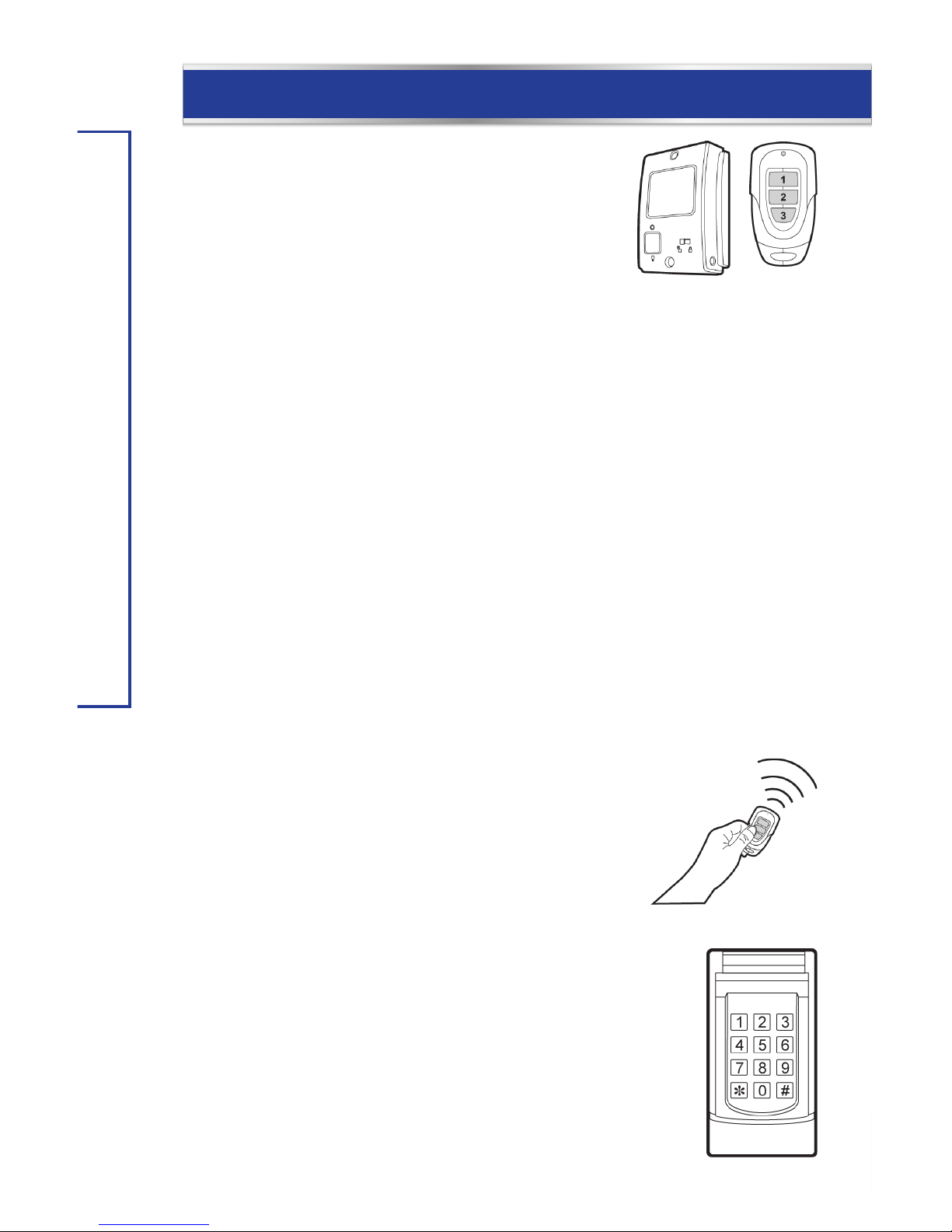
Remote Control
To activate the opener with the remote control, hold down the button
until the door begins to move. When the button is pressed, the light
indicator on the remote will flash. For remotes with multiple
buttons, press the button programmed to the desired operation.
Keypad Operation
Single Door Operation: Enter the pin code plus [#].
For example: 1 2 3 4 #.
Multiple Doors Operation: Enter the pin code plus [#] plus [door number].
For example:
Door 1: 1 2 3 4 # 1
Door 2: 1 2 3 4 # 2
Door 3: 1 2 3 4 # 3
Door 4: 1 2 3 4 # 4
Page 45

45
OPERATION
Mastercraft® Garage Door Opener Deluxe Wall Console (046-0508-6)
Press the large button on the wall console to
activate the garage door opener.
On the wall console there are 3 additional features:
1. Light feature.
2. Lock feature.
3. Door closer timer.
Light Feature:
The light button can be used to turn the opener light
on or off. The automatic timer is ignored—the light
will remain on until the button is pressed again.
Lock Feature:
The lock button (also known as vacation button) can be used to lock out all remote control
transmitters. The door can still be activated by wall console. Simply slide the switch to the
locked position and the opener will ignore all the radio signals. To unlock, slide the switch
to the unlocked position .
Door Closer Timer:
The opener has the option to program how long until the door closes automatically after it
has been opened. To change the setting of this timer, there is a slide switch on the side of
the wall console.
Slide switch position Function
Door Closer Timer Disabled.
3 The door will close automatically after 3 minutes.
10 The door will close automatically after 10 minutes.
30 The door will close automatically after 30 minutes.
Large button
NOTE:
• With the door closer timer enabled, the opener will beep every 10 seconds when the door is opened. The
beeping rate will increase as the timer is runs out, indicating the door is about to close.
Page 46

headline bars
46
headline bars
model no. 046-0265-2 | contact us 1-800-689-9928
OPERATION
To Open the Door Manually
In case of a power failure, or if the door becomes obstructed, pull the red trolley release
handle to disengage the opener from the door.
Flip the trolley release level up and raise or lower the door to re-engage the opener.
Use caution: if the door is open while disengaging, the door may drop.
WARNING
To prevent possible serious injury or death from a falling garage door:
• If possible, use emergency release handle to disengage trolley only when garage door is closed. Weak or
broken springs or unbalanced door could result in an open door falling rapidly and/or unexpectedly.
• Never use emergency release handle unless garage doorway is clear of persons and obstructions.
• Never use handle to pull door open or closed. If the rope knot becomes untied, you could fall.
Page 47

47
MAINTENANCE
MAINTENANCE
Once a Month
• Test the door balance. Manually operate door. If it is unbalanced or binding, call a trained
door systems technician.
• Check to be sure door opens and closes fully. Adjust limits and/or force if necessary.
• Test both the safety reversal system and the safety beam sensor system as shown on
page 37 of this manual.
Once Every Six Months
• Check the chain tension. Turnbuckle should be slightly above the rail. Adjust chain tension
as shown on page 15 of this manual.
• Once a Year
• Oil the door rollers, bearings and hinges.
Automatic Opening/Closing Force Adjustment
The opener will adjust the opening and closing force automatically so it operates at the most
efficient setting. To allow the opener to adjust the opening and closing force automatically,
operate the opener once after setting travel limits.
To operate the opener:
• Press the push button to open the door, until it reaches the
fully open position.
• Press the push button to close the door completely, until it
reaches the fully closed position.
You have now finished setting the opening and closing force.
In order to readjust the opening/closing force, you must first enter travel limit adjustment.
Force adjustment will proceed automatically after travel limit adjustment sequence.
Press
NOTE:
• After adjusting the Up/Down travel limits, the opener will re-adjust its opening and closing force during
the first opening and closing cycle. Therefore, it is important to pay attention not to obstruct the door
during the first opening and closing cycle after adjusting the travel limits. The opener has now finished
adjusting the opening and closing force.
• During the force adjustment, do not obstruct the door's travel or the safety beam sensor.
Page 48

headline bars
48
headline bars
model no. 046-0265-2 | contact us 1-800-689-9928
MAINTENANCE
WARNING
To prevent possible serious injury or death:
• Never allow small children near batteries.
• If battery is swallowed, immediately notify doctor.
Battery Disposal:
• Please dispose the used battery per municipal or provincial law.
Battery Replacement
All remotes come with battery installed. To
replace the battery, follow the instructions
below.
It is time to change the battery when the red
LED light on the remote does not turn on when
either button is pressed.
Lithium battery CR-2032 included (positive side up).
To replace the battery:
1. Undo the two screws on the back of the remote. The bottom case will then come off.
2. Take out the old battery.
3. Place the new battery in position.
4. Close the cover and reinsert two screws.
Install Keypad and Battery
Undo the screw on the bottom side of the keypad.
Remove the back plate.
Insert a AAA battery (1.5 V Alkaline type).
Mount the back plate with the mounting accessories.
Attach the keypad on the back plate and tighten the screw on the bottom of the keypad.
Page 49

49
TROUBLESHOOTING
TROUBLESHOOTING
LED Light
Flashing
LED
Display
Flashing
Symptom Solution
3 Flashes The wall console is
in lock mode. The
remote controls are
deactivated.
• Unlock the wall console.
5 Flashes
Overtime. The motor is
running continuously
over 30 seconds in one
direction.
• Ensure the opener is correctly
installed and attached to the
garage door.
• Adjust the travel limit to let the
opener open or close the door
within 30 seconds.
10 Flashes
Safety beam sensor
blocked.
• Check if the safety beam
sensor is misaligned.
• Check if any obstacle is
interfering with the beam path.
15 Flashes
The door is not fully
open or fully closed.
• Check if something is
obstructing the door.
• Re-adjust the travel limits.
• Re-adjust the opening and
closing force.
Continuous
Flashing
Wall console wire
shorted.
• Check the wall console wires
for a short.
Opener does not
operate from either
wall console or
remote.
• Check the opener’s AC outlet has power. Plug a lamp into the
outlet to check. If it does not turn on, check fuse box or circuit
breaker.
• Check the wall console wiring at the wall console's and
opener’s terminals, and be sure the remote is programmed into
the opener.
Opener tries to
operate, but the door
does not move.
• A door spring may have been broken. Visually inspect the door
hardware for any broken springs. Have a qualified garage door
service professional repair the door if any door hardware is
broken.
• In cold weather climates, check that the door is not frozen to
the ground or that snow build-up is not blocking the door.
Page 50

50
headline bars
model no. 046-0265-2 | contact us 1-800-689-9928
TROUBLESHOOTING
Opener operates from
remote but not from
wall console.
• Ensure the wiring connections are correct.
• Is the wall console lit? If not, disconnect low voltage wires to
wall button and momentarily touch them together. If opener
runs, replace wall button. If not, check wiring connections at
opener and check wire for shorts or breaks under wire holder.
Opener operates from
wall console but not
remote.
• Is the wall console in lock mode?
• Does remote indicator light glow when remote button is
pressed? If not, replace the battery.
• Has the opener learned the code of the remote? Repeat remote
programming steps on pages 39.
Door does not open
completely.
• Is something obstructing the door? Remove obstructions after
ensuring the door area is free of persons and any other objects.
• If door has been working properly but now doesn’t open all
the way, reset the travel limit adjustment. Be sure to run
a complete opening and closing cycles to reset the force
adjustment as well. Follow instructions on page 38.
Door does not close
completely.
• Is something obstructing the safety beam sensor? Ensure the
receiving beam sensor’s LED is on.
• Is something obstructing the door? Remove obstructions after
ensuring the door area is free of persons and any other objects.
• If the door has been working properly but, now, doesn’t open
all the way, reset the travel limits. Be sure to run a complete
opening and closing cycle to reset the force adjustment. Follow
instructions on page 38.
Opener light stays on.
• It is normal for the opener’s light to stay on for about 3 minutes
after each activation.
• If the opener’s light was turned on by the light button on the
wall console, it will stay on until the light button is pressed
again to turn the light off.
Opener activates by
itself.
• Check all remotes programmed into the opener. Check for
items pressing on any remote’s button.
• If a remote has been stolen, erase the opener’s memory (refer
to page 40 to prevent the lost remote from activating the
opener. Reprogram the remaining remotes into the opener
(refer to page 39).
• Check the wiring between the wall console and the opener.
Look for any wire holder that has cut into the wire’s insulation,
or wire that has been pinched by another object. Replace any
bad wiring.
• Examine the wiring at the opener’s terminals and at the wall
console's terminals. Look for any wire strands that are close to
or touching adjacent terminals.
Page 51

51
TROUBLESHOOTING
Door reverses for no
apparent reason.
• The door hardware may be binding causing the close door
force setting to be exceeded. Disengage the trolley and
manually check the door movement and balance. Lubricate
the door hardware as recommended by the garage door
manufacturer.
• Re-adjust the travel limits and force adjustments to ensure the
automatic force adjustment are set properly.
• Ensure the safety beam sensor is securely fastened and no
sunlight is shining directly onto the receiving sensor.
Opener is noisy.
• Adjust the chain tension (refer to page 16).
• Lubricate the door hardware as recommended by the garage
door manufacturer.
Opener won’t work
due to power failure.
• Use the emergency release handle to disconnect the opener
from the door. The door can be opened or closed manually until
power is restored.
Page 52

headline bars
OPTIONAL: PROGRAMMING
model no. 046-0265-2 | contact us 1-800-689-9928
52
OPTIONAL: PROGRAMMING
To SKYLINK® Internet Hub (046-0510-8; Sold separately)
1. Open SkylinkNet App and tap on “System Settings”.
2. Tap on “Set-up Wizard”.
3. Tap on “Add Device”.
4. Tap on “2-way Garage Door Opener”.
5. Name your garage door opener and location and tap on “Continue”.
6. Press the [SET] button on the GDO for 1 sec until LED shows [P]; then,
tap on “Learn Now”.
7. Tap on GDO icon to open/close the door. The icon shows the status of the door.
NOTE:
• Internet hub is not included.
Page 53

53
ACCESSORIES
Mastercraft® GARAGE DOOR OPENER
COMPACT REMOTE
Model no. 046-0507-8
Mastercraft® GARAGE DOOR OPENER
BACKUP BATTERY
Model no. 046-0504-4
Mastercraft® GARAGE DOOR OPENER
KEYLESS ENTRY SYSTEM
Model no. 046-0506-0
Mastercraft® GARAGE DOOR OPENER
PROGRAMMABLE LCD WALL CONSOLE
Model no. 046-0509-4
Mastercraft® GARAGE DOOR OPENER
INFRARED SAFETY SENSORS
Model no. 046-0505-2
ACCESSORIES
Page 54

headline bars
FCC
model no. 046-0265-2 | contact us 1-800-689-9928
54
FCC
This device complies with Part 15 of the FCC Rules. Operation is subject to the following
two conditions: (1) This device may not cause harmful interference and (2) This device must
accept any interference received, including interference that may cause undesired operation.
Warning:
Changes or modifications to this unit not expressly approved by the party responsible for
compliance could void the user’s authority to operate the equipment.
Note:
This equipment has been tested and found to comply with the limits for a Class B digital
device, pursuant to Part 15 of the FCC Rules. These limits are designed to provide reasonable
protection against harmful interference in a residential installation. This equipment
generates, uses and can radiate radio frequency energy and, if not installed and used in
accordance with the instructions, may cause harmful interference to radio communications.
However, there is no guarantee that interference will not occur in a particular installation. If
this equipment does cause harmful interference to radio or television reception, which can
be determined by turning the equipment off and on, the user is encouraged to try to correct
the interference by one or more of the following measures:
• Reorient or relocate the receiving antenna.
• Increase the separation between the equipment and receiver.
• Connect the equipment into an outlet on a circuit different from that to which the receiver
is connected.
• Consult the dealer or an experienced radio/TV technician for help.
Page 55

55
LIMITED WARRANTY
LIMITED WARRANTY
The motor on this Mastercraft product carries an 8 (eight) year LIMITED warranty against
defects in workmanship and materials. The parts, including the rail and belt, carry a
2 (two) year LIMITED warranty. The accessories carry a 1 (one) year LIMITED warranty.
This product is not guaranteed against wear or breakage due to misuse and/or abuse.
Made in China
Imported for
Mastercraft Canada Toronto, Canada M4S 2B8
 Loading...