

Page 1
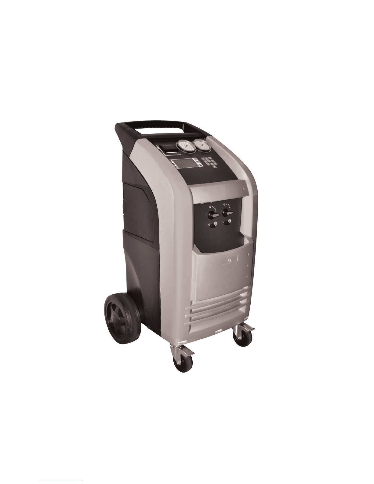
RECOVERY/RECYCLE/RECHARGE
Operating Instructions
Do not stop the recovery process. Permanent damage will occur that could void the warranty.
WARNING!!
Page 2

CONTENTS
INTRODUCTION 4
SAFETY SUMMARY 4
SAFETY INFORMATION 4
ELECTRICAL SHOCK HAZARDS 4
MOTION HAZARDS 5
FUME HAZARDS 5
HEAT/FREEZING HAZARDS 5
EXPLOSION/FLAME HAZARDS 5
ADDITIONAL SAFETY INFORMATION 5
CERTIFICATION 6
ABOUT THIS MANUAL 6
ABOUT YOUR AIR CONDITIONING RECOVERY/RECYCLE SERVICE CENTER 6
WARRANTY 6
GENERAL INFORMATION 6
PRINCIPLES OF OPERATION 7
SETUP 7
THE MACHINE 8
BASIC COMPONENTS 8
CONTROLS AND CONTROL SYSTEM 8
CONTROL PANEL FUNCTION KEYS 9
FUNCTION SELECTOR KEYBOARD 9
ALARMS 9
PRELIMINARY OPERATIONS 10
AUTOMATIC PROCEDURE 10
ASSISTED PROCEDURE 16
RECOVERY AND RECYCLING 17
VACUUM 18
VACUUM LEAK CHECKING 18
NEW OIL INJECTION 19
CHARGING REFRIGERANT 20
SET-UP 23
LAST RECOVERED QUANTITY 23
FILLING THE MACHINE TANK 23
PURGING NON-CONDENSABLE GASES 24
LANGUAGE 25
MEASURE UNITS 26
WEIGHT 26
PRESSURE 26
TEMPERATURE 26
SET DATE & TIME 27
SET-UP HEAD PRINTING 27
INSERT OPERATOR NUMBER 28
OPTION 28
INFORMATION 29
DATA 29
2
Page 3

COUNTERS 29
FILTER CONDITIONS 30
REF MANAGEMENT 30
PASSWORD 31
INFO: SW, LANGUAGE DB 32
ROUTINE MAINTENANCE 32
VACUUM PUMP 32
Oil Fill 32
Checking Oil Level 33
Oil Change 33
REPLACING THE DRYER FILTERS 33
FILLING THE NEW OIL CONTAINER 34
EMPTYING THE USED OIL CONTAINER 34
CHECKING THE SCALE RESPONSE 34
DATABASE CUSTOMIZATION 35
DATA ENTRY 35
USE 36
DELETION 36
DATABASE UPGRADE 36
CONTRAST 37
REPLACING THE PRINTER PAPER 37
CONVERSION CHART 37
3
Page 4

INTRODUCTION
This machine is ETL Laboratories approved, in compliance with SAE J2788. We are dedicated to solving the issues surrounding the safe
containment and proper management of refrigerants. Your new machine incorporates the latest technology and state of the art features to aid you in
servicing R134a air conditioning and refrigeration systems.
NOTICE:
The SAE J2788 standard has, by design made recycling machines more complex than previous models that some End Users might be familiar with.
Some noticeable changes that the End User should expect from ALL new recycling machines are the following.
1. RECOVERY TIME: The average recovery time is approximately 30 minutes. This time is necessary to meet the SAE J2788 standard which requires
that the machine recovers at least 95% of the AC system refrigerant and cleans the refrigerant to a minimum of 95% purity.
2. HOT WEATHER: As the ambient temperature approaches 100°F, some End Users have experienced an increase in recovery time. This is due
to the natural response of R134a when its temperature is elevated. R134a has difficulty transforming from a gas into a liquid state at elevated
temperatures. The transformation into liquid is necessary for the machine to complete the recovery process. The End User might notice the same
effect when performing a TANK CHARGING operation.
3. COLD WEATHER: As the ambient temperature approaches 50°F, some End Users have experienced an increase in recovery time. This is due
to the natural response of R134a when its temperature is lowered. R134a has difficulty transforming from a liquid into a vapor state at reduced
temperatures. The transformation into vapor is necessary for the machine to complete the distilling process. The End User might notice the same
effect when performing a TANK CHARGING operation.
SAFETY SUMMARY
The following safety information is provided as guidelines to help you operate your new system under the safest possible conditions. Any equipment
that uses chemicals can be potentially dangerous to use when safety or safe handling instructions are not known or not followed. The following
safety instructions are to provide the user with the information necessary for safe use and operation. Please read and retain these instructions for
the continued safe use of your service system.
SAFETY INFORMATION
Every craftsman respects the tools with which they work. They know that the tools represent years of constantly improved designs and
developments. The true craftsman also knows that tools are dangerous if misused or abused. To reduce risk of discomfort, illness, or even death,
read, understand, and follow the following safety instructions. In addition, make certain that anyone else that uses this equipment understands and
follows these safety instructions as well.
READ ALL SAFETY INFORMATION CAREFULLY before attempting to install, operate, or service this equipment. Failure to comply with these
instructions could result in personal injury and/or property damage.
RETAIN THE FOLLOWING SAFETY INFORMATION FOR FUTURE REFERENCE.
Published standards on safety are available and are listed at the end of this section under ADDITIONAL SAFETY INFORMATION.
The National Electrical Code, Occupational Safety and Health Act regulations, local industrial codes and local inspection requirements also provide a
basis for equipment installation, use, and service.
The following safety alert symbols identify important safety messages in this manual.
When you see one of the symbols shown here, be alert to the possibility of personal injury and carefully read the message that follows.
Never fill the tank to more than 80% of maximum capacity as this will not leave an expansion chamber for absorbing any pressure increases.
ELECTRICAL SHOCK HAZARDS
• To reduce the risk of electric shock, unplug the power supply cord from the outlet before attempting any maintenance or cleaning. Turning off
controls will not reduce this risk.
• Do not operate the machine with a damaged cord or plug — replace the cord or plug immediately. To reduce the risk of damage to electric plug
and cord, disconnect the power cord by pulling on the plug rather than the cord.
An extension cord should not be used unless absolutely necessary. Use of an improper extension cord could result in a risk of fire, electric shock
and component damage. If extension cord must be used, make sure:
a. That pins on plug of extension cord are the same number, size, and shape as those on plug on recycler.
b. That extension cord is properly wired and in good electrical condition; and
c. That the wire size is large enough for the length of cord as specified below:
Length of cord in feet: 25 50 100 150
AWG size of cord: 16 12 10 8
4
Page 5

MOTION HAZARDS
• Engine parts that are in motion and unexpected movement of a vehicle can injure or kill. When working near moving engine parts, wear snug fit
clothing and keep hands and fingers away from moving parts. Keep hoses and tools clear of moving parts. Always stay clear of moving engine
parts. Hoses and tools can be thrown through the air if not kept clear of moving engine parts.
• The unexpected movement of a vehicle can injure or kill. When working on vehicles always set the parking brake or block the wheels.
FUME HAZARDS
• FUMES, GASES, AND VAPORS CAN CAUSE DISCOMFORT, ILLNESS, AND DEATH! To reduce the risk of discomfort, illness, or death, read,
understand, and follow the following safety instructions. In addition, make certain that anyone that uses the equipment understands and follows
these safety instructions as well.
• Avoid breathing A/C refrigerant and lubricant vapor mist. Exposure may irritate eyes, nose, and throat. To remove R134a from the A/C system,
use service equipment certified to meet the requirements of SAE J2788--R134a recycling equipment. Additional health and safety information
may be obtained from refrigerant and lubricant manufacturers.
• Always perform vehicle service in a properly ventilated area. Never run an engine without proper ventilation for its exhaust.
• Stop the recycling process if you develop momentary eye, nose, or throat irritation as this indicates inadequate ventilation. Stop work and take
necessary steps to improve ventilation in the work area.
HEAT/FREEZING HAZARDS
• When under pressure, refrigerants become liquid. When accidentally released from the liquid state they evaporate and become gaseous. As they
evaporate, they can freeze tissue very rapidly. When these gases are breathed in, the lungs can be seriously damaged. If sufficient
quantities are taken into the lungs, death can result. If you believe you have exposed your lungs to released refrigerant, seek immediate medical
assistance.
• Refrigerants can cause frostbite and severe burns to exposed skin. Refrigerants are under pressure and can be forcibly sprayed in all directions if
carelessly handled. Avoid contact with refrigerants and always wear protective gloves and make certain other exposed skin is properly covered.
• Refrigerants can also severely injure or cause permanent blindness to unprotected eyes. Refrigerants are under pressure and can be forcibly
sprayed in all directions if carelessly handled. Avoid contact with refrigerants and always wear safety goggles.
EXPLOSION/FLAME HAZARDS
• Never recover anything other than the approved refrigerants as specified on the machine. Alternate refrigerants may contain flammables such as
butane or propane and can explode or cause a fire. Recovering alternate refrigerants will also void the warranty on your machine.
• For general safety reasons, at the end of the working day or in between services (when services do not immediately follow), see to it that all valves
on hoses and the machine are closed.
ADDITIONAL SAFETY INFORMATION
For additional information concerning safety, refer to the following standards.
ANSI Standard Z87.1 — SAFE PRACTICE FOR OCCUPATION AND EDUCATIONAL EYE AND FACE PROTECTION - obtainable from the American National
Standards Institute, 11 West 42nd St., New York, NY 10036, Telephone (212) 642-4900, Fax (212) 398-0023 - www.ansi.org
CAUTION: This equipment should be used in locations with mechanical ventilation that provides at least four air changes per hour or the
equipment should be located at least 18 inches (457 mm) above the floor, or the equivalent.
CAUTION: Do not pressure test or leak test R134a service equipment and/or vehicle air conditioning systems with compressed air. Some
5
Page 6

mixtures of air and R134a have been shown to be combustible at elevated pressures. These mixtures, if ignited, may cause injury or
property damage. Additional health and safety information may be obtained from refrigerant manufacturers.
ATTENTION: Technicians using this equipment must be certified under EPA Section 609 (Environmental Protection Agency).
WARNING: There is the possibility of refrigerant contamination in the refrigerant container or the mobile A/C system being serviced or
refrigerant container. Before recycling use proper equipment such as a refrigerant identifier, if necessary.
NOTE: Use only new refrigerant oil to replace the amount removed during the recycling process. Used oil should be discarded per
applicable federal, state, and local requirements.
The manufacturer shall not be responsible for any additional costs associated with a product failure including, but not limited to, loss of
work time, loss of refrigerant, cross contamination of refrigerant, and unauthorized shipping and/or labor charges.
IMPORTANT: R134a systems have special fittings (per SAE specifications) to avoid cross-contamination with R12 systems. DO NOT adapt
your unit for a different refrigerant — system failure will result.
PERIODICALLY INSPECT AND MAINTAIN REFRIGERANT HOSES AND SEALS TO ENSURE THAT HOSES AND SEALS PREVENT THE ADDITION OF
EXCESS AIR, DUE TO LEAKS, DURING THE RECOVERY PROCESS, WHICH WOULD INCREASE THE NCG LEVEL IN THE RECOVERED REFRIGERANT.
CERTIFICATION
All technicians opening the refrigeration circuit in automotive air conditioning systems must now be certified in refrigerant recovery and recycling
procedures to be in compliance with Section 609 of the Clean Air Act Amendments of 1990. For information on certification call MACS Worldwide at
(215) 631-7020.
ABOUT THIS MANUAL
This manual includes a SAFETY SUMMARY, MACHINE PREPARATION FOR USE, OPERATION procedures, and MAINTENANCE instructions, for your
Air Conditioning Service Center. Anyone intending to use the machine should become familiar with ALL the information included in this manual
(especially the SAFETY SUMMARY) before attempting to use it.
Before operating this machine for the first time, perform all PREPARATION FOR USE instructions. If your new machine is not properly prepared to
perform a service, your service data could be erroneous. In order to properly perform a complete air conditioning service, follow all procedures in the
order presented. Please take the time to study this manual before operating the machine. Then keep this manual close at hand for future reference.
Please pay close attention to the SAFETY SUMMARY and all WARNINGS and CAUTIONS provided throughout this manual.
ABOUT YOUR AIR CONDITIONING RECOVERY/RECYCLE SERVICE CENTER
Your machine incorporates a highly accurate electronic scale for determining charging weights, etc. Other functions can also be performed with
the electronic scale as you will discover during the operating procedures. Either standard or metric units of measure can be selected. Your new
machine has been designed specifically to use R134a, to operate within the objectives of the Montreal Protocol.
WARRANTY
This product is warranted against any defect in materials and/or construction for a period of 1 year from the date of delivery. The warranty consists
of free-of-charge replacement or repair of defective component parts or parts considered defective by the Manufacturer. Reference to the machine
serial number must be included in any requests for spare parts. This warranty does not cover defects arising from normal wear, incorrect or
improper installation, or phenomena not inherent to normal use and operation of the product.
NOTE: Regarding the above, the Manufacturer reminds the Customer that according to international and national laws and regulations in force the
goods are shipped at the sole risk of the latter and, unless otherwise specified in the confirmation of order phase, the goods are shipped uninsured.
The Manufacturer therefore declines any and all responsibility in merit of CLAIMS for damages due to shipping, loading and unloading, and
unpacking.
The product for which repair under guarantee is requested must be shipped to the manufacturer under the customer’s exclusive responsibility and
at the customer’s exclusive expense and risk. In order to avoid damage during shipping for repairs, the Manufacturer’s original packing must always
be used and scale must be locked prior to shipping, refer to Setup on page 7.
The manufacturer declines any and all responsibility for damage to vehicles on which recovery/recycling and recharging are performed if said
damage is the result of unskillful handling by the operator or of failure to observe the basic safety rules set forth in the instruction manual.
The warranty will expire automatically at the end of the twelve month period or whenever one of the following occurs: failure to perform
maintenance; use of improper maintenance procedures; use of unsuitable lubricants and/or tracer fluids; inept or improper use; repairs performed
by unauthorized personnel and/or with non-original spare parts; damage caused by shocks, fires, or other accidental events.
To activate the warranty, mail the attached warranty card.
GENERAL INFORMATION
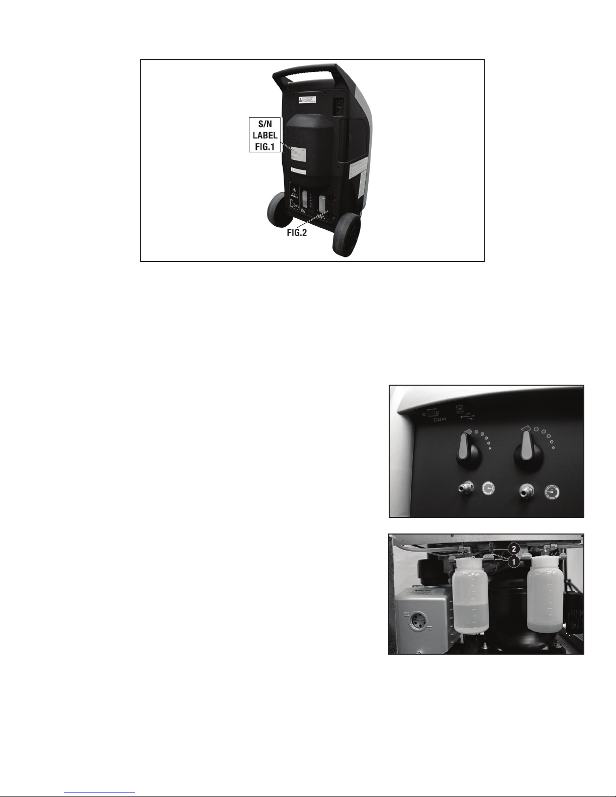
Machine identification information is printed on the data plate on the rear of the machine (see Figure 1). Overall machine dimensions:
Height:
Like any equipment with moving parts, the machine inevitably produces noise. The construction system, paneling, and special provisions adopted by
6
41.3 inch
Width:
23.6 inch
Depth:
21.6 inch
Weight:
176 lb
Page 7
the Manufacturer are such that during work, the average noise level of the machine is less than 70 dB (A).
NOTE: The machine is intended for indoor use only.
PRINCIPLES OF OPERATION
In a single series of operations, the machine permits recovering and recycling refrigerant with no risk of release into the environment, and also
permits purging the A/C system of humidity and deposits contained in the oil. The machine is equipped with a built-in evaporator/separator that
removes oil and other impurities from the refrigerant recovered from the A/C system and collects them in a container for that purpose. The fluid is
then filtered, recycled and returned to the tank installed in the machine. The machine also permits running certain operational and leak tests on the
A/C system.
SETUP
The machine is supplied fully assembled and tested. Referring to Figure 3, mount the
hose with the BLUE quick-connect coupling on the male threaded connector indicated by
the BLUE LOW PRESSURE symbol and the hose with the RED quick-connect coupling on
the male threaded connector indicated by the RED HIGH PRESSURE symbol.
Referring to Figure 4, remove the protection under the refrigerant scale as follows
(UNLOCK SCALE):
- Loosen the nut (Fig 4-2.)
- Loosen the screw (Fig. 4-1) two to four turns (do not remove from machine.)
- Tighten the nut (Fig. 4-2.)
NOTE: In the event that the equipment has to be transported; the refrigerant tank scale
MUST be locked in place as follows:
- Use two 10mm wrenches.
- Loosen the nut (Fig. 4-2.)
- Switch the machine on.
- Tighten the screw slowly (Fig. 4-1) until the display signals ZERO Ref. Available.
- Tighten the nut (Fig. 4-2) forcefully (using the second wrench to lock the screw
(Fig. 4-1).
- Check that the screw (Fig. 4-1) is actually locked, if necessary repeat the locking
operation from the beginning.
FIG. 3
FIG. 4
7
Page 8
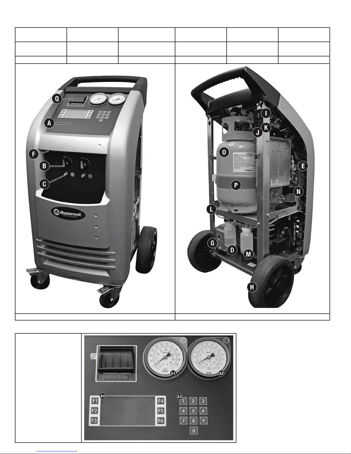
THE MACHINE
BASIC COMPONENTS (Refer to Figures 5, 6)
A) Control Console B) Service Valves
G) Vacuum Pump H) Wheels I) Main Switch
M) Used Oil Bottle N) Drier Filters O) Tank P) Tank Heater Q) Printer
C) High & Low Service
Ports
D) New Oil Bottle E) Sight Glass F) Serial Port
J) Socket for Electrical
Supply Plug
K) Fuse Holder L) Electronic Scale
FIG. 5 FIG. 6
CONTROLS AND CONTROL SYSTEM
Fig. 7
A1) High pressure gauge
A2) Low pressure gauge
A3) Keyboard
A4) LCD
8
Page 9
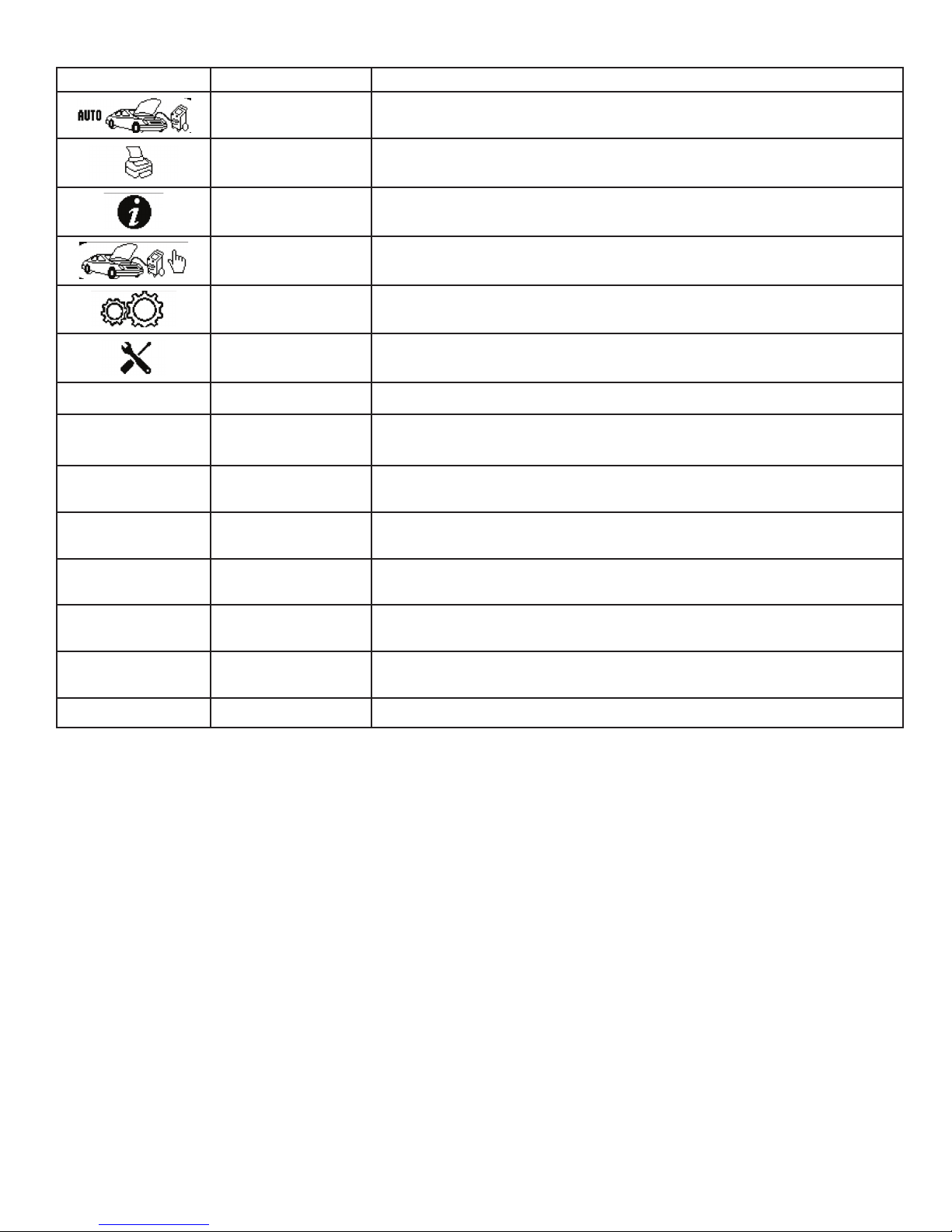
CONTROL PANEL FUNCTION KEYS
Choose control panel functions by pressing the FN key that appears beside the icon on the display.
ICON DESCRIPTION FUNCTION
AUTOMATIC PROCEDURE
PRINT Print a summary of the last procedure performed
INFO Activates a menu that contains all the information of the recycling machine
Activates a menu that helps the user set up an automatic recover/vacuum/vacuum leak
check/oil injection and charge sequence
▶
■
↵
↑
←
↓
→
ASSISTED PROCEDURE
SETUP Activates the setup menu of the recycling machine
CALIBRATION
START To start a procedure or operation shown on the display
STOP
ENTER To accept a procedure or operation shown on the display
UP ARROW Used for scrolling up through the menu items
LEFT ARROW Used for moving the cursor to the left
DOWN ARROW Used for scrolling down through the menu items
RIGHT ARROW Used for moving the cursor to the right
Activates a menu that helps the user to perform a recovery, vacuum, oil injection, or
charge operation individually
Activates the calibration menu of the recycling machine. Should only be performed by a
Qualified Service Center. Special tools and codes are needed
To stop a procedure or operation, silences the audible alarm or returns to the previous
screen
[DB]
FUNCTION SELECTOR KEYBOARD
F1: Press to launch the procedure or operation shown on the display.
F2: Press to interrupt the operation being performed -- recovery - oil discharge - vacuum/oil charging - charging. Press F1 to resume
operation from the point of interruption. Pressing F2 during an alarm state, error state, or end-of-operation state silences the audible
alarm.
F4: Press to confirm the procedure or operation flashing on the LCD.
↓: Press to move downward from one procedure or operation to another within a menu.
↑: Press to move upward from one procedure or operation to another within a menu.
NOTE: “Tank” and “Bottle” are both used to describe a refrigerant container.
ALARMS
HIGH PRESSURE ALARM: Beeper and LCD advise when the pressure of the fluid in the circuit reaches 290 psi (20 bar). The recovery
operation is automatically interrupted. See page 24, Purging Non-Condensable Gases.
FULL TANK ALARM: Beeper and LCD advises when the tank is filled to more than 80% of maximum capacity; that is,
24 lbs (10.8 kg.), the RECOVERY operation is automatically interrupted. To cancel this alarm, charge one or
more A/C systems before recovering any more refrigerant or, using a scale and a D.O.T. tank, charge enough
refrigerant into the D.O.T. tank so that the refrigerant available will be approximately 12 to 15 lbs. This
refrigerant can be reclaimed later should 69789/69789-H need to be re-filled again with refrigerant.
(See Empty Tank Alarm)
NOTE: Do not attempt to charge a new refrigerant tank (blue tank with a single port valve). These tanks are
not D.O.T. approved for refilling and only have a check valve in them that allows refrigerant to leave the tank.
Since these tanks have a check valve and DO NOT have pressure safety devices on them they cannot be
DATABASE Used to select a charge value from a database
9
Page 10

refilled by 69789/69789-H.
NOTE: Never transfer refrigerants to a cylinder or tank unless it is D.O.T. approved for refilling. D.O.T. approval
is indicated by the designation “DOT 4BA” or “DOT 4BW” stamped on a tank’s collar (handle.) If a refrigerant
tank is overfilled, it may explode! Failure to abide by these warnings may cause personal injury or death.
EMPTY TANK ALARM: Beeper and the LCD advise when the quantity of refrigerant fluid contained in the tank is too low. At this time
it will be necessary to bottle fill 69789/69789-H to approximately 12 to 15 lbs of refrigerant in order for the
alarm to clear.
SERVICE ALARM: Service Alarm: The first service alarm; when the total recovered amount of refrigerant reaches 114 lbs, a
beeper will sound and the LCD will display SERVICE ALARM. To clear the alarm, press F2.
After the first alarm is cleared, filters should be purchased to have ready when 69789/69789-H requires that
the filters be replaced. The second service alarm; when the total recovered amount of refrigerant reaches
132 lbs, a beeper will sound and the LCD will display ENTER FILTER CODE. There will also be 10 dots along
the bottom of the screen. To deactivate the alarm, the filters will need to be replaced (see page 34 Replacing
the dryer filters.)
NOTE: It is good practice to change the Vacuum pump oil when the filters are being changed. (see page 32,
Vacuum Pump)
LOW REFRIGERANT ALARM: Beeper and the LCD advise when the charging quantity set exceeds the amount of refrigerant available. The
minimum quantity of refrigerant is 4.50 lbs. If the gas available minus the charge quantity equals less than
4.5 lbs, 69789/69789-H will interrupt the attempt to charge and notify the operator that there is insufficient
refrigerant. At this time it will be necessary to tank charge 69789/69789-H to approximately 12 to 15 lbs of
refrigerant in order to perform a charge. For instance, if the gas available is 9.50 lbs and the charge
quantity is 1.80 lbs, then 9.50 lbs minus 1.80 lbs equals 7.70 lbs. 7.70 lbs is greater than 4.50 lbs so
69789/69789-H will perform the charge. If the gas available is 5.90 lbs and the charge quantity is 1.80 lbs,
then 5.90 lbs minus 1.80 lbs equals 4.10 lbs. 4.10 lbs is less than 4.50 lbs, so 69789/69789-H will not
charge and will let the operator know that there is insufficient refrigerant available.
PRELIMINARY OPERATIONS
Check that the main switch (Fig. 6-I, page 8) is set to 0. Check that all the machine valves are closed. Connect the machine to the electrical supply
and switch on. Check that the vacuum pump oil level indicator shows at least one-half full. If the level is lower, add oil as explained in the ROUTINE
MAINTENANCE section (page 32.) Check that in the new oil container (Fig. 6-D, page 8) there are at least 3.4 oz. (100 cc) of the oil recommended by
the manufacturer of the vehicle A/C system. Check that the oil level in used oil container (Fig. 6-M, page 8) is less than 6.7 oz. (200 cc.) Check the
machine’s data display to be sure there is at least 9 lbs (4.08 kg) of refrigerant in the tank. Should this not be the case, fill the on-board machine
tank from an external tank of appropriate refrigerant following the procedure described in the ROUTINE MAINTENANCE section (page 32.)
WARNING:
DO NOT STOP THE RECOVERY PROCESS. Stopping the recovery process will definitely cause damage to the Compressor and perhaps other
components. It will also cause the machine to fill up with unprocessed liquid refrigerant which will disable the machine from further use.
Damage due to STOPPING THE RECOVERY PROCESS could void the warranty.
AUTOMATIC PROCEDURE
In the automatic mode, all the operations are performed automatically: recovery and recycling, oil discharge, vacuum, new oil reintegration, and
charging. The values for the quantity of gas recovered, quantity of oil recovered, vacuum time, quantity of oil reintegrated, and quantity of
gas charged into the system are automatically printed at the end of all operations.
Connect the hoses to the A/C system with the quick-connect couplings, bearing in mind that BLUE must be connected to the low pressure side and
RED to high pressure. If the A/C system is equipped with a single quick-connect coupling for high or low pressure, connect only the relative hose.
Check that the high- and low-pressure taps are closed. Start the vehicle engine and switch on the air conditioner. Allow both to run for about 5 to 10
minutes with the passenger compartment fan at full speed. THEN TURN OFF THE A/C SYSTEM AND SHUT-OFF THE VEHICLE’S ENGINE.
Turn on the machine, from main menu:
F1
F2
F3
Select AUTOMATIC PROCEDURE, the following screen is displayed (only if the hardware for hybrid vehicles is installed in the machine).
10
F4
F5
F6
Page 11

SELECT
↵
Standard vehicle
■
Hybrid vehicle
Gas Filling xxg
↑
↓
Press F4 ↵ to confirm STANDARD VEHICLE or press the DOWN ARROW ↓ and then F4 ↵ to select HYBRID VEHICLE.
NOTE: When HYBRID VEHICLE is selected the OIL phase of the AUTOMATIC PROCEDURE is disabled.
The following message appears:
warning
■
using pag oil or
tracer in hybrid vehicles can damage the
compressor
Gas Filling xxg
↵
↑
↓
Press F4 ↵ to continue
use specic oil
with a separate
device
Press ENTER
■
↵
↑
Gas Filling xxg
↓
Press F4 ↵ to continue, a pop-up window with vacuum settings will be displayed:
vacuum 20 MIN
↵
■
Gas Filling xxg
↑
↓
Set the vacuum time by keying in the desired time. To accept the time value that is already there, press F4. The machine will automatically perform
a 2 minute automatic leak check when the time value is 11 minutes or longer. Automatic leak check will start after 9 minutes of vacuuming. If a
leak is detected, the machine will notify the operator that a leak was detected and will not continue vacuuming. If no leak is detected, the machine
will continue vacuuming for the time remaining.
Oil No
Automatic Oil
Oil xxcc
■
Gas Filling xxg
↵
↑
↓
1) Press F4 ↵ to skip Oil Refill.
2) Scroll to “Automatic Oil” with the DOWN ARROW ↓ and confirm it by pressing F4 ↵.
11
Page 12
Oil No
Automatic Oil
Oil xxcc
↵
■
NOTE: When the Vacuum operation is completed the system will automatically reintegrate with the same quantity of oil extracted during
Recovery.
3) Scroll to “Oil” with the DOWN ARROW ↓, then use the keys 0 to 9 to type the volume of oil to be automatically reintegrated after
Vacuum, then press F4 ↵ to confirm.
NOTE: cc = ml
■
The following summary screen will be displayed:
■
Gas Filling xxg
Oil No
Automatic Oil
Oil 30cc
Gas Filling xxg
AUTOMATIC PROCEDURE
Vacuum 20min
Oil 30cc
Ref Charge xxg
↑
↓
↵
↑
↓
↵
↑
DB
1. Set the quantity of refrigerant required for the A/C system to be charged. Following are examples for each set of units.
Lb, the display will have 4 digits, two digits then a decimal point and then two digits. The cursor moves from the left to the right. If the desired
charge is 1.75 lbs, then you will enter 0 1 7 5.
Oz, the display will have 3 digits. The cursor moves from the right to the left. If the desired charge is 36 oz’s, then you will enter 0 3 6.
Gr, the display will have 5 digits. The cursor moves from the right to the left. If the desired charge is 980 grams, the you will enter 9 8 0.
Kg, the display will have 3 digits, two digits then a decimal and then one digit. The cursor moves from the right to the left. If the desired charge is
1.5 Kg’s then you will enter 1 5.
Lb-oz, the display will have 4 digits, two digits then a colon and then two digits. The cursor moves from the left to the right. If the desired charge
is 1 lb’s 7 oz’s then you will enter 0 1 0 7.
AUTOMATIC PROCEDURE
Vacuum 20min
Oil 30cc
Ref Charge 1.75lb
■
DB
NOTE: When working with A/C systems with a single high-pressure (RED) coupling, set the charging quantity 3 oz. (.19 lb or 85g) more than the
required quantity, since in this case it will be impossible to recover the residual refrigerant from the hoses after charging.
NOTE: In most cases, the quantity of refrigerant being charged into the A/C system is given on a data plate inside the engine compartment of the
vehicle. If you do not know the correct quantity, consult the relevant manuals.
2. DATABASE ADVANCE: Press the DATABASE [DB] key, the following screen will appear on the display.
↓
↵
↑
↓
12
Page 13

DATABASE ADVANCED
Acura
Alfa Romeo
■
Use DOWN ARROW ↓ and UP ARROW ↑ to select the required vehicle brand and press F4 ↵ to confirm. The display will now show the various
models (for example, if the brand chosen was BMW):
■
Use DOWN ARROW ↓ and UP ARROW ↑ to select the model required press F4 ↵ to confirm. The following will appear on the display:
Audi
BMW
Buick
Cadillac Charge
BMW
Alpina B7 2007-08
Alpina B7 2011-12
Alpina V8 2003
128 2008-09
128 2011-12
135 2008-09
↵
↑
↓
↵
↑
↓
■
AUTOMATIC PROCEDURE
Vacuum 20min
Oil 30cc
Ref Charge 01.79lb
↵
↑
↓
The machine will be ready to enter the correct quantity of refrigerant. Confirm by pressing the F4 ↵ key. See customizing the database (page 35) to
add user defined vehicle charge values.
Insert Plate N.
■
.......................
Press F4
Gas Filling xxg
↵
←
→
Type the plate of the car, use RIGHT ARROW → and LEFT ARROW ← to move inside plate number; press ENTER ↵ to confirm. If no plate number is
needed, press F4 to continue.
NOTE: the numerical keys include an alphabet that is used similar to text messaging; for example: press “2” once to display “A”, twice to display
“B”, three times for “C”, four times for “2”.
If “Hybrid vehicle” was selected, the graphic display will show the flushing procedure:
▶
■
Press F1 ▶ to continue, the following screen will be displayed:
AUTOMATIC PROCEDURE
HP & LP Hoses
Flushing Procedure
F1 to continue
F2 to exit
↵
↑
↓
13
Page 14

▶
■
Press F1 ▶ to begin hoses flushing, the following screen will be displayed:
Connect and open HP
and LP hoses to the
side of the machine
F1 to continue
F2 to exit
Hoses Flushing
Please Wait
AUTOMATIC PROCEDURE
↵
↑
↓
■
ACP>26inHg
Hose flushing consists of 4 cleaning rounds, at the end of the 4 phases the following screen will be displayed:
NOTE: The hose flushing process takes approximately 10 minutes to complete. DUE TO THE SAFETY ISSUES RELATED TO HYBRID VEHICLES DO
NOT STOP THIS PROCESS.
AUTOMATIC PROCEDURE
Disconnect hoses
from machine, then
■
Press F4 ↵ to continue with the AUTOMATIC PROCEDURE. The following screen will be displayed:
▶
connect to AC system
Press F4 Charge
RECOVERY/RECYCLING
Open high and low
service port valves
Press F1
↵
■
Open the high and low pressure taps on the machine and press F1 ▶ to begin the RECOVERY/RECYCLING process. During this phase, the graphic
display will show the following:
RECOVERY/RECYCLING
Ref recov. 00.00lb
Tp 87 psi T 68.7˚F
■
Upon completion of recovery, the machine will stop and automatically discharge the used oil from the A/C system if any was present during recovery.
The oil discharge operation lasts 6-14 minutes depending on the ambient temperature and the amount of refrigerant recovered. During the oil
discharge operation, the following screen will be displayed:
Acp 2 psi
14
Page 15

RECOVERY/RECYCLING
Recovery paused
oil draining
■
If any residual refrigerant is left in the A/C system, as indicated by an increase in pressure during the oil discharge phase, recovery will automatically
restart.
NOTE: Stopping the recovery phase before the oil is discharged may damage the recovery/recycle machine’s compressor.
Upon completion of discharge, the machine will check for the presence of air in the tank, and if it’s necessary, purge the non-condensable gases.
The alarm will sound continuously and the display will show:
please wait
Time: 6 min
Recov. Oil oml
RECOVERY/RECYCLING
Air Purge
Tp 137 psi T 80.4˚F
■
The Recovery/Recycle machine will automatically purge non-condensable gases (NCGS) if excess NCGS are detected at the end of recovery. Allow
the unit to complete this procedure, eliminating the chance of NCGS being charged to the AC system.
NOTE: Charging may not run to completion due to pressure balance between the internal refrigerative storage tank and the A/C system. If this occurs,
close the high pressure valve (leaving the low-pressure side open), start the vehicle and switch on the A/C system. The unit is equipped with a tank
heater to limit this occurrence. When the charging operation is complete, the machine will display the following dialog boxes:
▶
■
▶
Acp 0 psi
Air Purge
REF CHARGING
END OF CHARGE
CLOSE HIGH AND LOW
SERVICE PORT VALVES
F1: TO CONTINUE
REF CHARGING
START ENGINE
TURN ON A/C SYSTEM
■
F1: TO CONTINUE
▶
■
▶
■
REF CHARGING
VERIFY A/C SYSTEM PRESSURES
F1: TO CONTINUE
REF CHARGING
CLOSE HP PRESSURE COUPLER
F1: TO CONTINUE
15
Page 16

▶
■
REF CHARGING
Open high and low
service port valves
Turn on A/C system
F1: to continue
■
ASSISTED PROCEDURE
WARNING:
DO NOT STOP THE RECOVERY PROCESS. Stopping the recovery process will definitely cause damage to the Compressor and perhaps other
components. It will also cause the machine to fill up with unprocessed liquid refrigerant which will disable the machine from further use.
Damage due to STOPPING THE RECOVERY PROCESS could void the warranty.
In the assisted procedure mode, all the operations can be performed individually. The values for the quantity of gas recovered, quantity of oil
recovered, vacuum time, quantity of oil reintegrated, and quantity of gas charged into the system are automatically printed at the end of each single
operation.
F1
F2
REF CHARGING
ALLOW HIGH AND LOW
PRESSURE TO EQUALIZE
CLOSE ALL VALVES
F2: WHEN COMPLETE
F4
F5
F3
From main menu:
Select the ASSISTED PROCEDURE, the following screen is displayed (only if the hardware for hybrid vehicles is installed in the machine).
SELECT
F6
↵
Standard vehicle
■
Hybrid vehicle
Gas Filling xxg
↑
↓
Press F4 ↵ to confirm STANDARD VEHICLE or press the DOWN ARROW ↓ and then F4 ↵ to select HYBRID VEHICLE.
NOTE: When HYBRID VEHICLE is selected the OIL phase of the AUTOMATIC PROCEDURE is disabled and the HOSE FLUSHING operation is activated.
The following message appears:
warning
■
using pag oil or
tracer in hybrid
vehicles can damage
the compressor
Gas Filling xxg
↵
↑
↓
Press F4 ↵ to continue
16
Page 17

use specic oil
with a separate
device
Press ENTER
■
Gas Filling xxg
↵
↑
↓
Press F4 ↵ to continue
ASSISTED PROCEDURE
Hose Flushing
■
Since hybrid was selected, the hose flushing procedure will need to be performed to ensure that no cross contamination will occur. Select hose
flushing and press F4 ↵.
Recovery/Recycling
Vacuum
Ref Charge xx.xx lb
▶
HP & LP HOSES
FLUSHING PROCEDURE
F1 to continue
F2 to exit
■
F1 to continue
▶
Connect and open HP
and LP hoses to the side of the machine
F1 to continue
F2 to exit
■
F1 to continue
▶
HOSE FLUSHING
PLEASE WAIT
ACP >26 inHg
■
Hose flushing consists of 4 cleaning rounds. At the end of the 4 phases, the following screen will be displayed.
NOTE: The hose flushing process takes approximately 10 minutes to complete. Due to the safety issues related to hybrid vehicles, do not stop this
process.
■
RECOVERY AND RECYCLING
Connect the hoses to the A/C system with the quick-connect couplings, bearing in mind that BLUE must be connected to the low-pressure side and
RED to high pressure. If the A/C system is equipped with a single quick-connect coupling for high or low pressure, connect only the relative hose.
Check that the high- and low-pressure taps are closed. Start the vehicle engine and the air conditioner and allow both to run for 5 to 10 minutes
HOSE FLUSHING
END OF SEQUENCES
F2 to exit
17
Page 18

with the passenger compartment fan at full speed. Switch off the vehicle engine.
From ASSISTED PROCEDURE, the following screen will be displayed:
ASSISTED PROCEDURE
Recovery/Recycling
■
Press F4 ↵ to confirm “Recovery/Recycling,” a pop-up window will be displayed:
▶
■
Press F1 ↵ to confirm “Recovery/Recycling.” The following screen will be displayed:
■
Vacuum
Oil
Ref Charge xx.xxlb
Recovery/Recycling
Open high and low service port valve
Press F1
Gas Filling xxg
Insert Plate N.
.......................
Press F4
Gas Filling xxg
↵
↑
↓
↵
←
→
Type the plate of the car, use RIGHT ARROW → and LEFT ARROW ← to move inside plate number; press F4 ↵ to confirm.
NOTE: The numerical keys include an alphabet that is used similar to text messaging; for example: press “2” once to display “A”, twice to display
“B”, three times for “C”, four times for “2”.
The following screen will be displayed:
Recovery/Recycling
▶
■
Open the high and low pressure taps on the machine and press the START to begin the refrigerant recovery/recycling phase. During this phase, the
graphic display will show the quantity of refrigerant recovered. The machine checks whether or not there is air in the bottle and, if necessary, purges
the non-condensable gas. The alarm will sound continuously and an AIR PURGE warning will be displayed. The machine will automatically discharge
any non-condensable gas. Allowing the machine to fully complete the procedure will reduce the risk of return flows, which may cause excessive
non-condensable gas to be recharged into the air conditioning system. Upon completion of recovery, the machine will stop and discharge, while
automatically displaying the used oil extracted from the A/C system during the recovery phase. The oil discharge operation lasts 6-14 minutes. If any
residual refrigerant in the A/C system should increase in pressure during this phase, the machine will automatically begin recovering the refrigerant.
VACUUM
Use the quick-connect couplings to connect the hoses to the A/C system, bearing in mind that BLUE must be connected to the low pressure side
and RED to high pressure. If the system is equipped with a single quick-connect coupling for high or low pressure, connect only the relative hose.
Open high and low
pressure taps, then
Press F1 to continue
F2 to exit
VACUUM LEAK CHECKING
The machine will automatically perform a 2 minute AUTOMATIC LEAK CHECK when the time value is 11 minutes or longer. The AUTOMATIC LEAK
CHECK will start after 9 minutes of vacuuming. If a leak is detected the machine will notify the operator that a leak was detected and it will
not continue vacuuming. If no leak is detected, the machine will continue vacuuming for the time remaining. (Detection of micro leaks are not
guaranteed.)
From the ASSISTED PROCEDURE, scroll down with the DOWN ARROW ↓, select “Vaccum,” then press F4 ↵.
18
Page 19

Recovery/Recycling
Vacuum
■
NOTE: The oil phase is disabled in case of hybrid vehicles.
Enter the vacuum time and press F4 ↵.
Oil
Ref Charge xx.xxlb
Vacuum 20 min
ASSISTED PROCEDURE
↵
↑
↓
↵
■
Gas Filling xxg
↑
↓
The following screen will be displayed:
VACUUM
▶
■
Open the high- and low-pressure taps of the machine and press F1 ▶.
■
NEW OIL INJECTION
This operation can be carried out ONLY following a vacuum operation and before charging. From the ASSISTED PROCEDURE, scroll down with DOWN
ARROW ↓, select “Oil”:
Vacuum 20min
Open high and low
service port valves
F1: to continue
F2: exit
VACUUM
Time Left 20min
HEATER*
ACp = >26 inhg
Tp = 86 psi
■
*The OIL phase is disabled in case of hybrid vehicles.
Press F4 ↵ to confirm, a pop-up window with oil settings will be displayed.
■
Enter the amount of oil, then press F4 ↵.
ASSISTED PROCEDURE
Recovery/Recycling
Vacuum*
Oil*
Ref Charge xx.xxlb
Oil 0 cc
Hybrid Vehicle
Gas Filling xxg
↵
↑
↓
↵
↑
↓
19
Page 20

Oil NO
Manual Oil 30 cc
↵
The following screen will be displayed:
NOTE: cc = ml
■
■
▶
■
Gas Filling xxg
→ 3 → 0 →
Oil NO
Manual Oil 30 cc
Gas Filling xxg
Oil Injection
Oil 30 ml
Press F1 to continue
F2 to exit
↑
↓
↵
↑
↓
Open the high and low-pressure taps (if the A/C system is equipped with a single quick-connect coupling for high or low pressure, open only the
relative tap) of the machine, press F1 ▶.
Oil Injection
■
CHARGING REFRIGERANT
From ASSISTED PROCEDURE, scroll with the DOWN ARROW ↓, select “Ref Charge”:
■
DB
*The OIL phase is disabled in case of hybrid vehicles.
Set the quantity of refrigerant required for the A/C system to be charged using one of the two procedures below.
1. Manual Operation: Set the quantity for the charge. Following are examples for each set of units.
Lb, the display will have 4 digits, two digits then a decimal point and then two digits. The cursor moves from the left to the right. If the desired
charge is 1.75 lbs, then you will enter 0 1 7 5.
Oz, the display will have 3 digits. The cursor moves from the right to the left. If the desired charge is 36 oz’s, then you will enter 0 3 6.
Gr, the display will have 5 digits. The cursor moves from the right to the left. If the desired charge is 980 grams, the you will enter 9 8 0.
Kg, the display will have 3 digits, two digits then a decimal and then one digit. The cursor moves from the right to the left. If the desired charge is
1.5 Kg’s then you will enter 1 5.
Lb-oz, the display will have 4 digits, two digits then a colon and then two digits. The cursor moves from the left to the right. If the desired charge
is 1 lb’s 7 oz’s then you will enter 0 1 0 7.
20
End of oil injection
procedure
Press F2
ASSISTED PROCEDURE
Recovery/Recycling
Vacuum
Oil*
Ref Charge xx.xxlb
↵
↑
↓
Page 21

NOTE: When working with A/C systems with a single high-pressure (RED) coupling, set the charging quantity 3 oz. (.19 lb or 85 g) more than the
required quantity, since in this case it will be impossible to recover the residual refrigerant from the hoses after charging.
Recovery/Recycling
■
DB
■
DB
DATABASE ADVANCED: press DATABASE [DB] key, the following screen will appear on the display:
■
Vacuum
Oil
Ref Charge 01.75lb
Recovery/Recycling
Vacuum
Oil
Ref Charge 01.75lb
Acura
Alfa Romeo
Audi
BMW
Buick
Cadillac Charge xxg
AUTOMATIC PROCEDURE
→ 0 → 1 → 0 → 7
AUTOMATIC PROCEDURE
DATABASE ADVANCED
↵
↑
↓
↵
↑
↓
↵
↑
↓
Use DOWN ARROW ↓ and UP ARROW ↑ to select the required vehicle brand and press F4 ↵ to confirm. The display will now show the various
models (for example, if the brand chosen was BMW):
BMW
Alpina B7 2007-08
Alpina B7 2011-12
■
Use DOWN ARROW ↓ and UP ARROW ↑ to select the model required and press F4 ↵ to confirm. The following will appear on the display:
■
DB
Alpina V8 2003
128 2008-09
128 2011-12
135 2008-09 Charge xxg
Recovery/Recycling
Vacuum
Oil*
Ref Charge 01.79lb
ASSISTED PROCEDURE
↵
↑
↓
↵
↑
↓
See Customizing the Database (page 35) to add user defined vehicle charge values.
Insert Plate N.
.......................
↵
■
Type the plate of the car, use RIGHT ARROW → and LEFT ARROW ← to move inside plate number; press F4 ↵ to confirm.
NOTE: the numerical keys include an alphabet that is used similar to text messaging; for example: press “2” once to display “A”, twice to display
Press F4
Gas Filling xxg
←
→
21
Page 22

“B”, three times for “C”, four times for “2”.
The following screen will be displayed:
▶
REF CHARGING
Ref Charging
Ref 01.79 lb
■
Open the high- and low-pressure taps (if the A/C system is equipped with a single quick-connect coupling for high or low pressure, open only the
relative tap) of the machine and press F1 ▶.
Note: Charging may not run to completion due to pressure balance between the internal tank and the A/C system. If this occurs, close the valve
on the high pressure quick connect coupling (leaving the low-pressure side open), turn on the vehicle and switch on the A/C system. The unit is
equipped with a tank heater to limit this occurrence. When the charging operation is complete, the machine will display the following:
▶
■
▶
Open high and low valves
Press F1
REF CHARGING
END OF CHARGE
CLOSE HIGH AND LOW
SERVICE PORT VALVES
F1: TO CONTINUE
REF CHARGING
START ENGINE
TURN ON A/C SYSTEM
■
F1: TO CONTINUE
▶
■
▶
■
▶
■
REF CHARGING
VERIFY A/C SYSTEM PRESSURES
F1: TO CONTINUE
REF CHARGING
CLOSE HP PRESSURE COUPLER
F1: TO CONTINUE
REF CHARGING
OPEN HIGH AND LOW
SERVICE PORT VALVES
TURN ON A/C SYSTEM
F1: TO CONTINUE
22
Page 23

■
SETUP
LAST RECOVERED QUANTITY
To see how much refrigerant was recovered during the last recovery phase.
REF CHARGING
ALLOW HIGH AND LOW
PRESSURE TO EQUALIZE
CLOSE ALL VALVES
F2: WHEN COMPLETE
F1
F2
F3
Select F5:
■
Select LAST RECOVERED QTY, Press F4 ↵:
■
Last Recovered Qty
Tank Charging
Air Purge
Language
Measure Units
Set Date & Time
LAST RECOVERED QTY
F2: MAIN MENU
SETUP
01.50 LB
F4
F5
F6
↵
↑
↓
↵
↑
This valve gets updated after each complete recovery phase.
FILLING THE MACHINE TANK
This operation must be performed whenever the available refrigerant fluid in the tank is less than 9 lbs (4.8 kg) and must be performed when the
“Empty Tank” alarm is displayed. Recommended capacity is between 10 and 15 lbs. Obtain a tank of R134a. Connect the tank adapter fitting
(69788-332) to the R134a tank. Then, connect the high pressure hose from the tank to the high pressure valve on the machine. Open both the valve
on the external tank and the high pressure valve on the machine. If the external tank is not supplied with a liquid valve, turn it upside down to obtain
a higher delivery rate.
F1
F2
F3
At the MAIN MENU select F5.
↓
F4
F5
F6
23
Page 24

Select Tank Charging and press F4 ↵.
The following screen will be displayed:
■
Last Recovered Qty
Tank Charging
Air Purge
Language
Measure Units
Set Date & Time
SETUP
↵
↓
▶
Tank Charging
Set amount: xx.x lb
Min=xx Max=xx lb
■
F1 to continue
F2: reset
Set the quantity of refrigerant to be transferred to the machine bottle (the quantity must be between the limit values suggested by the machine) and
press F1 ▶ to confirm:
▶
■
Press F1 ▶:
▶
■
Tank Charging
Use the HP hose to connect external tank
and
Press F1 to continue
Tank Charging
Open the external tank valve, open HP
valve and
Press F1 to continue
F2 to exit
Press F1 ▶, the machine will now fill the machine bottle with the preset quantity. When the quantity minus 1 lb is reached, the machine will stop
and display:
▶
■
Close the bottle tap and press F1 ▶ , the machine will stop automatically after having recovered the residual refrigerant from the hoses. Close the
high-pressure tap. Disconnect the external bottle. Switch the machine off.
PURGING NON-CONDENSABLE GASES
If 69789/69789-H should become loaded with excessive tank pressure due to the accumulation of NCG (Non-Condensable Gases) it will be
necessary that the operator purge the NCG manually. The operator will need to start the manual purge and the machine will automatically stop the
purge when the proper pressure is reached. The operator can also stop the purge manually before the machine determines the proper pressure.
24
Tank Charging
Close external bottle tap
Press F1 to continue
F2 to exit
Page 25

F1
F4
F2
F3
At the MAIN MENU select F5.
SETUP
Last Recovered Qty
Tank Charging
■
Select AIR PURGE and press F4 ↵, the following screen will be displayed:
▶
■
Air Purge
Language
Measure Units
Set Date & Time
Air Purge
Bottle Pres 107 psi
Tank Temp 75.7˚F
F1: to purge air
F2: Main Menu
F5
F6
↵
↑
↓
Press F1 ↵ to start the air purge:
Air Purge
Bottle Pres 107 psi
Tank Temp 75.7˚F
■
If no air purge is necessary, the following screen will be displayed:
▶
Air Purge
No purge necessary
■
LANGUAGE
F1
F1: Back
F1: Back
F2: Main Menu
F4
F2
F3
At the MAIN MENU select F5.
F5
F6
25
Page 26

SETUP
Last Recovered Qty
Tank Charging
■
Select LANGUAGE and press F4 ↵, the following screen will be displayed:
Air Purge
Language
Measure Units
Set Date & Time
↵
↓
SETUP
↵
English
■
Use the DOWN ARROW ↓ and UP ARROW ↑ to scroll the available languages. Select a language and press F4 ↵. The machine will reset in a few
seconds.
MEASURE UNITS
F1
F2
F3
At the MAIN MENU select F5.
Italiano
Francais
Espanol
Deutsch
Portuguese
↑
↓
F4
F5
F6
SETUP
Last Recovered Qty
Tank Charging
■
Select MEASURE UNITS, press F4 ↵:
Air Purge
Language
Measure Units
Set Date & Time
Weight lb
Pressure Unit psi
Temperature ˚F
■
Setup Heading Print
Insert Operator N.
WEIGHT
Press F4 ↵ to select the units (lb, oz, gr, kg or lb:oz). Press F2 ■ to exit.
PRESSURE
Use DOWN ARROW ↓ to select “Pressure” then press F4 ↵ to change from psi to bar. Press F2 ■ to exit.
↵
↓
↵
←
→
TEMPERATURE
Use DOWN ARROW ↓ to select “Temperature” then press F4 ↵ to change from ˚F to ˚C. Press F2 ■ to exit.
26
Page 27

SET DATE & TIME
The machine holds date and time data in memory for about one year, even if switched off.
At the MAIN MENU select F5.
Select DATE & TIME, Press F4.
F1
F2
F3
■
▶
■
SETUP
Last Recovered Qty
Tank Charging
Air Purge
Language
Measure Units
Set Date & Time
Set Date & Time
hh:mm:ss - dd/mm/yy
F1: modify
F2 to exit
F4
F5
F6
↵
↓
Press F1 ▶ to modify “Date & Time.” Type actual hours and minutes, then day, month and year. When finished press F2 ■ to exit.
SETUP HEADING PRINT
F1
F2
F3
At the MAIN MENU select F5.
SETUP
F4
F5
F6
↵
SETUP HEAD PRINTING
■
Insert Operator N.
Option
↑
↓
Select SETUP HEAD PRINTING, press F4 ↵:
SETUP HEAD PRINTING
Insert Name Workshop
................................................
■
↵
←
→
27
Page 28

Type the shop name in the space provided. Use RIGHT ARROW → and LEFT ARROW ← to move the cursor then Press F4 ↵. A second line for shop
name appears. Fill in the second line and press F4 ↵ or press F4 ↵ to skip to the second shop name line.
SETUP HEAD PRINTING
Insert Phone Number
................................................
■
↵
←
→
Type the “Phone Number” use RIGHT ARROW → and LEFT ARROW ← to move then Press F4 ↵ to confirm.
NOTE: the numerical keys include an alphabet that is used similar to text messaging; for example: press “2” once to display “A”, twice to display
“B”, three times for “C”, four times for “2”.
INSERT OPERATOR NUMBER
F1
F2
F3
At the MAIN MENU select F5.
F4
F5
F6
■
SETUP
Setup Head Printing
INSERT OPERATOR N.
Option
↵
↑
↓
Select INSERT OPERATOR N., press F4 ↵:
INSERT OPERATOR N.
................................................
■
↵
←
→
Type the “Operator Number,” use RIGHT ARROW → and LEFT ARROW ← to move; then Press F4 ↵ to confirm and exit.
NOTE: the numerical keys include an alphabet that is used similar to text messaging; for example: press “2” once to display “A”, twice to display
“B”, three times for “C”, four times for “2.”
OPTION
For Manufacturers Only.
28
Page 29

INFORMATION
DATA
This menu shows all the data read by the machine.
At the MAIN MENU select INFO F3.
Select DATA, press F4 ↵:
F1
F2
F3
■
■
INFO MENU
Data
Counters
Filter Conditions
Ref Management
Password
Info: SW, Language DB
DATA
Ref avail 09.58lb
Oil 150cc
Acp 15psi
Tank Press 98psi
Tank Temp 74.4˚F
F4
F5
F6
↵
↑
↓
↓
-Ref avail.: quantity of refrigerant available in the storage bottle.
-Oil: total quantity of oil in all the oil containers.
-Acp: pressure in the vehicles air conditioning system.
-Tank Press: refrigerant storage bottle pressure.
-Tank Temp: temperature of the tank temperature probe.
COUNTERS
F1
F2
F3
At the MAIN MENU select INFO F3.
Data
Counters
■
Filter Conditions
Ref Management
Password
Info: SW, Language DB
F4
F5
F6
INFO MENU
↵
↑
↓
Select COUNTERS, press F4 ↵:
29
Page 30

▶
Recovery 18.89lb
Service 18.10lb
■
This screen displays the total value for: refrigerant recovered, service alarm counter, vacuum time, refrigerant charging and tank charging.
Press F1 ▶ to print all values.
FILTER CONDITIONS
Vacuum 85min
Gas Chg. 09.49lb
Cyl. Chg. 03.75lb
F1 to print
COUNTERS
At the MAIN MENU select INFO F3.
Select FILTER CONDITIONS, press F4 ↵:
F1
F2
F3
■
■
INFO MENU
Data
Conditions
Filter Conditions
Ref Management
Password
Info: SW, Language DB
FILTER CONDITIONS
13.44%
F2 to exit
F4
F5
F6
↵
↑
↓
This screen shows the percentage of used filter life.
Press F2 ■ to exit.
REF MANAGEMENT
This machine memorizes the various operations involving refrigerant: recovery, filling the A/C system and filling the storage tank. A record is kept for
each operation: data and time, type of operation, displaced amount, operator number, refrigerant availability in the storage tank. The machine can
store up to 100 records. Beginning with the 90th record, a message is displayed to inform the operator of how many operations can still be recorded.
F1
F2
F3
At the MAIN MENU select INFO F3.
30
F4
F5
F6
Page 31

INFO MENU
Data
Conditions
■
Select REF MANAGEMENT, press F4 ↵:
Filter Conditions
Ref Management
Password
Info: SW, Language DB
Ref Management
0 - delete
■
1 - print
Press “1” to print all the records in batches of 25, beginning with the most recent:
Press “0” to delete all the records in memory.
When finished press STOP ■ to exit.
PASSWORD
↵
↑
↓
At the MAIN MENU select INFO F3.
Select PASSWORD, press F4 ↵:
F1
F2
F3
■
■
INFO MENU
Data
Counters
Filter Conditions
Ref Management
Password
Info: SW, Language DB
PASSWORD
............................................
F4
F5
F6
↵
↑
↓
A 4-digit password may be entered to block the machine. Once a code is put in, it will be necessary to input the code in order to use automatic
procedure, assisted procedure or setup.
Entering the passcode “0000” removes the block.
31
Page 32

INFO: SW, LANGUAGE, DB
MAX
MIN
2
3
MIN
MAX
4
5
6
90016
VACUUM PUMP OIL
16 oz (450ml)
F1
F2
F3
At the MAIN MENU select INFO F3.
■
Select INFO: SW, LANGUAGE DB, press F4 ↵:
■
INFO MENU
Data
Counters
Filter Conditions
Ref Management
Password
Info: SW, Language DB
SOFT VERSION
SW: x.xx
DBA: xxxxxxxxx
Text: xx.xx
F4
F5
F6
↵
↑
↓
F2 to exit
This screen displays the name of the current software revision and the current database software that is loaded in the machine’s memory.
ROUTINE MAINTENANCE
VACUUM PUMP
Perform the operations listed below on a routine basis in order to ensure the best operation of the vacuum pump:
When filling or replacing the pump oil, use only the oil recommended by the manufacturer.
FIG. 8
OIL FILL - (NEW MACHINE)
This vacuum pump has been tested at the factory and shipped with only trace amounts of oil. OIL MUST BE ADDED BEFORE OPERATING! Failure to
add oil will damage the cartridge and void warranty.
NOTE: Make sure the oil drain valve located below the front casing is closed before attempting to add oil (Fig 8-3.)
32
Page 33

1) Disconnect the machine from the electrical supply.
2) Remove the rear cover (6 screws.)
3) Unscrew the oil fill/muffler plug (Fig 8-2.)
4) Oil Bottle: A) Remove oil bottle cap
B) Remove the silver foil
C) Attach the filling top (be sure to remove the red cap) (Fig. 8-5.)
D) Attach the filling hose (Fig. 8-6.)
5.) Slowly add oil until oil level rises to the top of the oil level line. Do not overfill with oil! (Fig 8-4.)
6.) Replace the oil fill/muffler plug (Fig 8-2.)
7.) Re-install the rear cover (6 screws.)
CHECKING OIL LEVEL
The oil level in the sight glass should be between the max and min line (Fig 8-4.) If oil level falls below the MIN line add oil per oil fill instructions.
OIL CHANGE
The vacuum pump oil must be replaced:
1) Every 120 working hours, or
2) When the filter/dryers are replaced, or
3) At the beginning or end of every season, or
4) Whenever the oil changes color due to absorption of moisture.
Before beginning the oil change procedure, obtain an empty 16 oz. (1 pint) or larger container in which to collect the used oil.
1) Disconnect the machine from the electrical supply.
2) Remove the rear cover (6 screws.)
3) Unscrew the oil fill/muffler plug (Fig 8-2.)
4) Unscrew the drain plug (Fig. 8-3.)
5) Allow all the oil to run out into a disposal container (drain clearance is less than 3.95 inches.)
6) Close the drain plug (Fig. 8-3.)
7) Pour in new oil through the fill hole until the level rises to the midpoint on the indicators (Fig. 8-4.)
8) Replace the oil fill/muffler plug (Fig. 8-2.)
9) Replace the rear plastic cover on the machine (6 screws.)
NOTE: When changing the vacuum pump oil, dispose of used oil as per federal, local and state regulations.
REPLACING THE DRYER FILTERS
Replace the filters when the machine alerts you. Replace the filters only with
Mastercool part numbers: 69788-FLTRPK. When changing the filters you will need
a filter code. To obtain a filter code, please call Mastercool Inc. Technical Service at
888-825-6989.
LOCK OUT: If you are changing the filters because of the Second Service alarm (see
page 10) and has locked out 69789/69789-H, then a filter code will be needed to
re-set 69789/69789-H. Before changing the filters, call Mastercool Inc. Technical
Service at 888-825-6989 to get the filter code.
NO LOCK OUT: If the filters are being changed at an unscheduled time, no filter
code will be needed to continue operating 69789/69789-H. Only when the machine
reaches the pre-programmed recovery quantity of 132 lbs will it lock out. Once the
machine is locked out, the filter code will be needed to re-set the 69789/69789-H.
(See LOCK OUT)
To change the filters, proceed as described below (refer to Fig. 9):
1) Disconnect the machine from the electrical supply.
2) Wear protective gloves and glasses.
3) Remove the rear plastic cover from the machine (6 screws.)
4) Close both of the valves on top of tank.
5) Close the valve (Fig. 9-1) under the filter (Fig. 9-4.)
6) Connect the low pressure quick-connect coupling to the male connector
(Fig. 9-2) under the filter (Fig. 9-4.)
7) Connect the machine to the electrical supply and turn the machine on.
8) Put in the filter code. (Only if locked out) To put in the filter code, you will need to
use the down arrow key to move the cursor to the next character. To input a letter, continue to press the same number with the corresponding
FIG. 9
33
Page 34

letter until the desired letter appears. Once the entire code is showing on the screen, press the F4 key.
9) Using Assisted Procedure, start a recovery operation (NOTE: the valve under the low pressure filter [Fig. 9-3] should be open).
10) When oil draining is reached, immediately close the valve (Fig. 9-3) under the filter (Fig. 9-5) and turn the machine off.
11) Disconnect the machine from the electrical supply.
12) Disconnect the low pressure quick-connect coupling from the connector (Fig. 9-2) under the filter (Fig. 9-4).
13) Replace the filters. IMPORTANT: The filter replacement must be performed as quickly as possible in order to avoid possible contamination by
moisture in the ambient air.
14) Open the valve (Fig. 9-1) under the filter (Fig. 9-4) and the valve (Fig. 9-3) under the filter (Fig. 9-5).
15) Open both valves on top of the tank.
16) Connect the machine to the electrical supply and turn the machine on. (Leave the rear cover off at this time)
17) Press F1 when the machine displays “INTERRUPTED, F1: TO CONTINUE.”
18) Press F2 when the machine displays “ERROR SYSTEM EMPTY.”
19) Tank charge about 1 lb (-500g) of refrigerant to charge the machine circuit.
20) While the machine is recovering, use an electronic leak detector to check the seal on the connections that were opened to replace the filters. Re tighten if necessary.
21) Turn the machine off and replace the rear plastic cover on the machine. (6 screws)
22) The machine is now ready for normal use.
FILLING THE NEW OIL CONTAINER
It is good practice to fill the oil container whenever the oil level falls below 3.4 oz (100 cc) in order to guarantee that there will be sufficient oil for
topping off during successive operations. Always refer to the information provided by the A/C system manufacturer for oil specifications (oil is not
supplied.)
Remove the new oil container from its holder. Unscrew the container while holding the cap in place. Fill the new oil container with the correct
quantity of oil, of suitable type and grade. Screw the new oil container back on and replace the new oil container in the holder.
EMPTYING THE USED OIL CONTAINER
This operation must be performed whenever the oil level exceeds 6.7 oz (200 cc.)
Procedure: Remove the container from its holder. Unscrew the container while holding the cap in place. Empty the used oil into a suitable container
for used oils. Screw the container back in place while holding the cap in place. Carefully replace the container into its holder. (Dispose of used oil
as per your federal, local and state regulations.)
CHECKING THE SCALE RESPONSE
Turn the unit on and go to the data screen (F3.) Note the Refrigerant Available value. Hang the 500g test weight that was supplied with the machine
from the hook under the scale. (Fig 10-7) The “REF AVAILABLE” should go up by 500g+/-28g, 1.10lb +/-.06lb or 18oz +/-1oz depending on what
units the machine is set at. If the results of the test are not within these specifications, it is recommended that the scale be re-calibrated. The scale
re-calibration should be done by a qualified Service Technician. The equipment necessary for scale re-calibration is not supplied with 69789/69789H.
34
FIG. 10
Page 35

DATABASE CUSTOMIZATION
F1
F2
F3
At the MAIN MENU select either AUTOMATIC or ASSISTED PROCEDURE.
Recovery/Recycling
Vacuum
■
DB
At the Ref Charge step, press the DATABASE [DB] key, the following screen will appear on the display:
■
Oil
Ref Charge 00.00lb
Acura
Alfa Romeo
Audi
BMW
Buick
Cadillac Charge xxg
ASSISTED PROCEDURE
DATABASE ADVANCED
F4
F5
F6
↵
↑
↓
↵
↑
↓
Press the UP ARROW ↑, select “User Defined.”
DATABASE ADVANCED
Subaru
Suzuki
Toyota
■
Press F4 ↵, the following screen will appear on the display:
▶
■
DATA ENTRY
To enter customized data, press F1. The following screen will be displayed:
Volkswagen
Volvo
User Dened
xxg
DATABASE ADVANCED
????
????
????
????
????
????
↵
↑
↓
↵
↑
↓
35
Page 36

DATABASE ADVANCED
■
Model Name:
..............................................
↵
←
→
Type in the vehicle model, use RIGHT ARROW → and LEFT ARROW ← to move inside; press F4 ↵ to confirm.
NOTE: the numerical keys include an alphabet that is used similar to text messaging; for example: press “2” once to display “A,” twice to display
“B,” three times for “C,” four times for “2.”
The following screen will be displayed:
DATABASE ADVANCED
■
Model Name:
Abcde Fghilmn
Model Quantity:
..............................................
↵
←
→
Type in the corresponding refrigerant quantity in grams, press F4 ↵ to confirm.
USE
To use the customized data, scroll with the DOWN ARROW ↓ and UP ARROW ↑ to the desired vehicle model:
DATABASE ADVANCED
▶
■
DELETION
To delete custom data fields, scroll the DOWN ARROW ↓ and UP ARROW ↑ to the desired vehicle model and press “0” (ZERO). An alarm signal will
sound and the following screen will be displayed.
▶
■
Abcd Efgh
Lmno Pqrs
????
????
????
????
DATABASE ADVANCED
Abcd Efgh
Xxx g
DELETE?
F1 : yes F2: no
↵
↑
↓
Press F1 ▶ to confirm deletion or F2 ■ to exit without deletion.
NOTE CONCERNING THE DATABASE: We have taken all due care in gathering and entering the information contained in the database. The database
data must nevertheless be considered purely indicative; the manufacturer declines any and all responsibility for incorrect data.
DATABASE UPGRADE
Database upgrades are available. Call 973-252-9119 and ask for details.
36
Page 37

CONTRAST
Keys 4 and 5 may be used to adjust the screen contrast. Key 4 decreases contrast; key 5 increases contrast.
NOTE: Contrast control is active only with the machine in the main menu.
REPLACING THE PRINTER PAPER
Use only heat-sensitive paper of the type described below.
Paper width: 58mm
Maximum paper roll diameter: 40mm
Alternative paper roll sizes: 2 1/4” x 55’
2 1/4” x 80’
CONVERSION CHART
Ounces (oz) to pounds (lbs): divide by 16
Pounds (lbs) to ounces (oz): multiply by 16
Ounces (oz) to grams (g): multiply by 28.4
Grams (g) to ounces (oz): divide by 28.4
Pounds (lbs) to kilograms (kg): divide by 2.205
Kilograms (kg) to pounds (lbs): multiply by 2.205
Kilograms (kg) to ounces (oz): multiply by 35.27
Ounces (oz) to kilograms (kg): multiply by 0.0284
If you have difculty with a procedure please call Mastercool’s Technical Service at 973-252-9119
69789/89H-INST1
37
 Loading...