

Page 1
Owner’s Manual
Manual de Operación
CAUTION
SAVE AND READ THESE
IMPORTANT INSTRUCTIONS
Read all instructions carefully before setting up and
operating this unit. This manual was designed to provide you with important information needed to setup,
operate, maintain, and trouble-shoot your cooler.
Failure to follow these instructions may damage
and/or impair its operation and void the warranty.
U.S. Models:
MMB10, MMB12, MMB14 & MMPC12
Mexico Modelos:
MMB10, MMB12 & MMB14
PRECAUCIO´N
LEA Y CONSERVE ESTE MANUAL
Lea todas las instrucciones cuidadosamente antes
de montar y operar esta unidad. Este manual fue
diseñado para proveerle importante información
necesaria para instalar
problemas en su enfriador. La falla en seguir estas
instrucciones puede dañar y/o afectar la operación
del enfriador y anular la garantía.
, operar
, mantener y detectar
1450 E. Grant Street, Phoenix, Arizona U.S.A.
www.AdobeAir.com 602-257-0060
AP059719 2/2008
Av. Carr. Miguel Alemán #6061, Col. América, Cd. Guadalupe, Nuevo León, México, C.P. 67130
www.Impco.com.mx (81)-8144-5440
Page 2
1
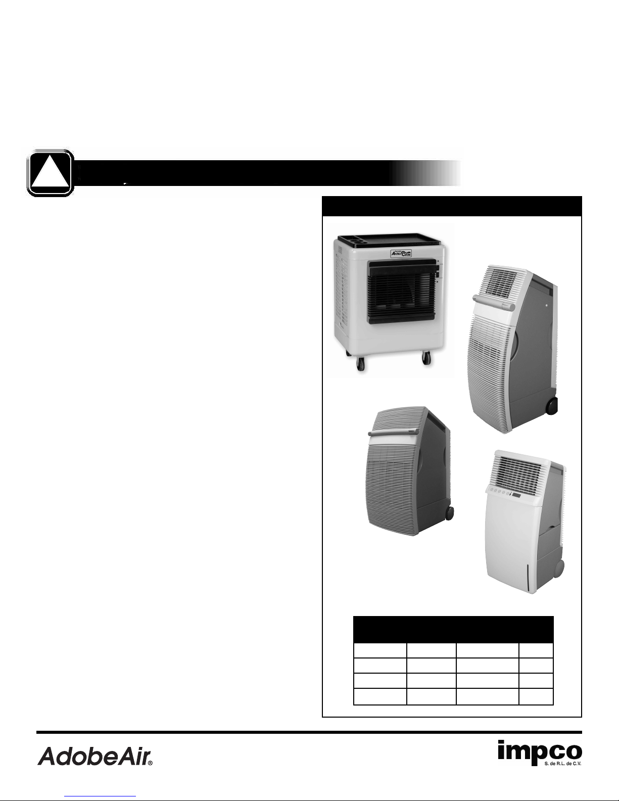
INTRODUCTION
Evaporative cooling works on the principle of heat absorption
by moisture evaporation. Simply put, heat is removed from the
ir as water evaporates. You feel this principle in action when
a
you step out of a swimming pool or shower; you feel immediately cooler as water evaporates from the surface of your skin.
!
WARNINGS AND SAFETY RULES
WARNING…
To reduce the risk of electric shock, fire or injury:
• Read instructions and labels carefully.
Always unplug the electric cord to your cooler before
•
you work on the cooler.
• Your cooler will run on 120 Volt AC, 60 Hz (cycle)
current only.
Your evaporative cooler works on the same principle. Hot outside air is pulled through water-saturated pads, where the air is
ooled by evaporation and then discharged from the cooler. In
c
order for your cooler to work at maximum efficiency, it must
have hot air to draw in (from an open door or window) and an
outlet to vent out the air (window or vent). To learn more about
evaporative cooling, visit our website at www.AdobeAir.com.
Other Mobile Products by AdobeAir
MMB8
• Plug into three-prong grounded GFCI protected
electrical receptacle only.
• Do not operate if plug or cord are damaged in any way.
• Do not step on or roll over power cord with heavy or
sharp objects.
• Do not operate unit unless all panels are securely in
place.
• Remove the plug from the electrical receptacle by
pulling on the plug and not the cord.
• Test the GFCI receptacle or breaker monthly to ensure
it is functioning properly.
• Do not operate near open containers of flammable
liquids or gases.
Never wash your cooler cabinet with a garden hose;
•
water may harm the motor and pump.
• If the unit is damaged or it malfunctions, do not continue to operate it. Refer to the warranty or troubleshooting
section at www.AdobeAir.com or call AdobeAir Customer
Service Department at (602) 257-0060.
P12
MMB8 500 ft
P700 500 ft
P10 700 ft
P12 1,000
P10
P700
Cools Water Motor
Up T
Capacity
o
2
4.5 Gallons
2
2.5 Gallons 1/12
2
6 Gallons
2
ft
12 Gallons
HP
1/8
1/8
1/3
1450 E. Grant Street, Phoenix, Arizona U.S.A.
www.AdobeAir.com 602-257-0060
AP059719 2/2008
Av. Carr. Miguel Alemán #6061, Col. América, Cd. Guadalupe, Nuevo León, México, C.P. 67130
www.Impco.com.mx (81)-8144-5440
Page 3
2
ASSEMBLY INSTRUCTIONS
Unpacking the Mobile MasterCool®.
molded plastic tray not attached. Remove the plastic tray from the carton and
then remove the cooler from the carton.
Grille Installation.
cooler you must complete the grille installation.
Before attempting to use your new Mobile MasterCool
The unit is shipped with the
CAUTION: Handle the grille with care it may have
sharp edges or burrs.
!
Using the four Phillips screws and lock washers (included) start each screw
into each path, then tighten for assembly of the grill to the front of the cabinet.
DO NOT OVER TIGHTEN. See Figure 5
Installing the casters.
attached to the cabinet bottom. If wheels are not attached then locate the
wheels inside of the cooler and attach them to the cabinet bottom using the
bolts included.
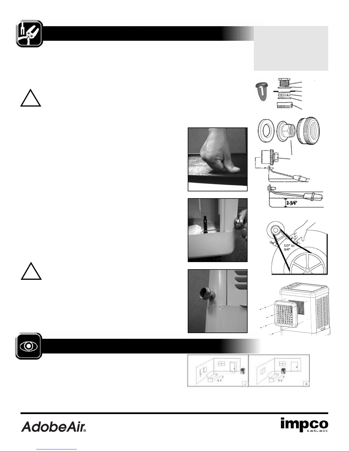
Attaching the plastic tray.
by lifting them up and out of the cooler cabinet. Locate the parts bag in the
cooler and attach the tray top using the push rivets provided. (Picture 1)
Installing the drain bushing and plug.
to Figure 1 and install the drain bushing and cap through the hole
provided in the bottom of the cooler.
Installing the float valve and adapter.
float to the side leg of the cooler using the hole provided. The garden hose
adapter attaches to the brass inlet fitting on the float valve. Verify that the hose
washers are properly in place. (Picture 2)
Connecting to Water
with water and drained. The cooler should be located on level ground.
Connect to a water supply using a commercial grade garden hose (supplied by
customer) connected to the adapter on the float valve and turn on the water.
Verify water tight connections by visually examining both the float / hose connection and the drain plug. (Picture 2)
Some models ship with the wheels already
Remove the side pad frames from the cooler
If it is not already installed, refer
Refer to Figure 2 and attach the
.
Move the cooler to an area where it can be filled
CAUTION: Water inlet pressure should be limited to a
maximum of 105 PSI or an inline pressure regulator
!
should be installed.
Adjusting the water level.
shown by adjusting the float.
Connecting to a Power Supply
120 Volt AC 60 Hz grounded GFCI protected electrical power sup
Note:
Improper voltage will burn out the motor and pump windings and will
void the warranty.
Refer to Figure 3 and set the water height as
.
Plug the gro
d plug directly into a
unde
ply.
Check Belt Tension.
This applies only to models
with belt drive construction.
Check belt tension (Figure 4)
by pushing downward on it.
proper tension will allow
deflection 1/2˝ to 3/4˝. To
adjust belt tension, loosen
bolt in slot of motor support
bracket, adjust to proper
tension and retighten bolt.
Picture 1
Picture 2
TOOLS REQUIRED
• 3/8˝Open End Wrench
ox End Wrench
3/8
˝
B
•
• 6
˝
Adjustable Wrench
˝
• 7/16
• #2 Phillips Screwdriver
Push Rivet
Box End Wrench
D
rain Bushing
W
asher
Cooler Bottom
Lock Nut
Washer Inside
Cap
H
ose Adapter
Figure 4
Cap
Figure 2
Figure 3
igure 1
F
LOCATION
Always make sure the unit is operated on a level surface. The
best location for it is near a partially opened window or door
where hot outdoor air can be drawn into the unit. This cooler is
portable, but use caution when rolling the unit to avoid splashing and spilling of water. Cool air can best be directed through
the space by using a partly opened window or door
that is situated on the opposite side of the
1450 E. Grant Street, Phoenix, Arizona U.S.A.
www.AdobeAir.com 602-257-0060
, ideally one
AP059719 2/2008
Picture 3
Figure 5
space from the cooler. This allows the cooled air to be moved
through the space and exhausted back outdoors which is
critical to proper performance of the cooler.
Av. Carr. Miguel Alemán #6061, Col. América, Cd. Guadalupe, Nuevo León, México, C.P. 67130
www.Impco.com.mx (81)-8144-5440
Page 4
3
USE & OPERATION
1. If your model has locking casters, make sure the two
locking casters have been locked to prevent the cooler
from moving before turning on the fan.
2. Turn on the water supply to the cooler. The hose connection
to the float valve provides an automatic method of refilling
the water supply as water evaporates.
3. For best results, turn the pump on a few minutes before
turning on the blower fan. This allows the cooling pads to
pre-wet for best efficiency.
4. Whenever possible, operate the blower fan at low speed for
maximum cooling. When cooling is not required you can
operate the unit as a fan by turning on the blower fan only
and leaving the pump turned off.
CAUTION
Do not operate the unit with pads or
!
grille removed.
CAUTION
Unplug the electrical cord to the cooler
!
before attempting to work on or service
the cooler.
CLEANING & MAINTENANCE
Periodic Drying of Pads. For best results allow pads to
dry after each operation by turning off the pump 15 minutes
before turning off the fan blower motor.
Periodic Draining of Sump. The entire water sump
should be drained at least once weekly to reduce mineral buildup. The failure to regularly drain the entire water sump will
greatly increase the mineral deposits and reduces the expected
life of the cooling pads. This could result in early replacement
of the pads at the owner’s expense. Use a damp cloth and wipe
off any mineral deposits that appear outside or inside the unit
at least once per week of use.
Lubrication. The pump and blower motors do not require
lubrication. For belt driven blower wheel models only, the
blower shaft bearings need periodic lubrication. The oil cups
on the blower shaft bearings should be filled with a good grade
SAE20W or 30W oil when necessary. Under normal use, oiling
is required every three months of operation. DO NOT OVER OIL.
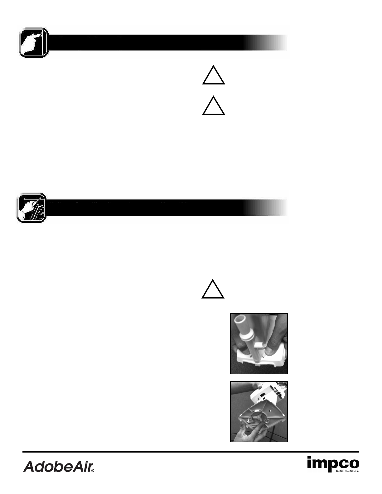
Cleaning Water Pump. (Pictures 5 and 6) Disassemble
and clean the water pump as follows.
• Use a mild detergent solution and wash all deposits from
the inside around the impeller and impeller base plate.
• Spin the impeller to dislodge any foreign material.
(Picture 6) Rinse and reinstall impeller base plate.
• Reinstall pump into the cooler.
CAUTION
Do not allow the pump to fall over and
!
become submerged in the water. Water
will damage the pump motor.
Picture 5
• Disconnect power supply to the cooler.
Access the pump by lifting the pad frames up and out of
•
the cooler. Remove pump from cooler.
• To prevent breakage, carefully release the four snap-out
tabs and lift impeller base plate from the pump body.
(Picture 5)
1450 E. Grant Street, Phoenix, Arizona U.S.A.
www.AdobeAir.com 602-257-0060
AP059719 2/2008
Picture 6
Av. Carr. Miguel Alemán #6061, Col. América, Cd. Guadalupe, Nuevo León, México, C.P. 67130
www.Impco.com.mx (81)-8144-5440
Page 5
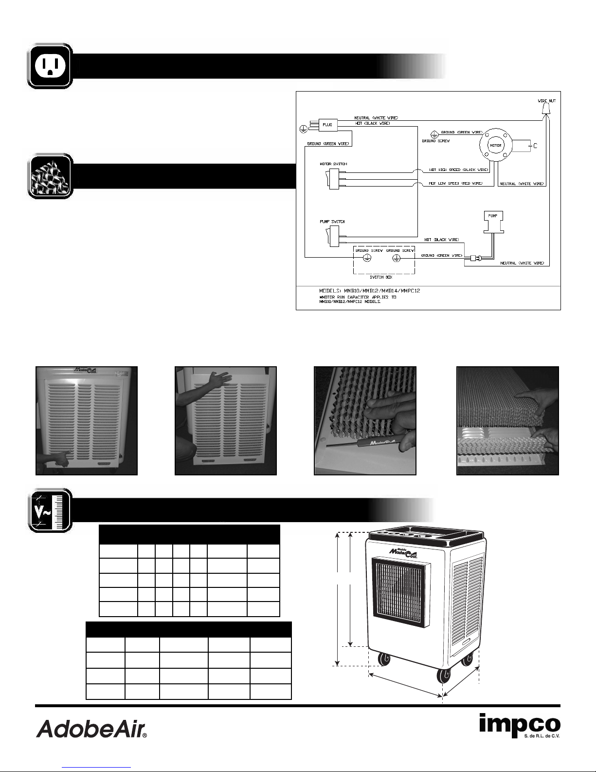
ELECTRICAL
D C
A
B
lectrical wiring on your unit is not required as the unit has
E
been wired at the factory. For your future reference, the wiring
diagram in Figure 7 shows rocker switches, two-speed motor,
capacitor and pump.
COOLING PAD REPLACEMENT
igure 7
F
4
The cooling pads should be changed at least every two years.
Check and clean them at the beginning of the season and
clean and reverse them in the middle of the season. The pads
may need to be replaced more frequently depending on local
conditions and the maintenance schedule followed.
Replacement Instructions:
To remove pad assemblies from the unit, lift up, pull out and then
down. Lay the metal side down on a flat surface and remove the
pad retainers. The MasterCool pad can now be removed. Rinse
off pad assembly, then install new MasterCool pad and retainer.
Replacement filter pads are available at your cooler dealer. See
pictures 7-10.
Picture 7
Picture 8
Picture 9
Picture 10
SPECIFICATIONS AND DIMENSIONS
Model Dimensions (in)
ABCD
MMB10 22 20 27.5 32.7 6.4 Gallons 60 lb
MMB12 26.5 25 33 38.7 7.2 Gallons 119 lb
MMB14 34 31 35.4 41 14.5Gallons 130 lb
MMPC12
Model Motor Frequency Volts Current
1450 E. Grant Street, Phoenix, Arizona U.S.A.
www.AdobeAir.com 602-257-0060
MMB10 1/8 HP 60 Hz 120 3.0 Amps
MMB12
MMB14
MMPC12 1/3 HP 60 Hz 120 5.5 Amps
26.5 26 31 35.7 7.2 Gallons 95 lb
1/3 HP 60 Hz 120 5.5 Amps
1/2 HP
60 Hz
Water Shipping
Capacity Weight
120
AP059719 2/2008
7.5 Amps
Av. Carr. Miguel Alemán #6061, Col. América, Cd. Guadalupe, Nuevo León, México, C.P. 67130
www.Impco.com.mx (81)-8144-5440
Page 6

5
TROUBLESHOOTING
The following troubleshooting guide is intended to address the most common symptoms and is by no means exhaustive. If
symptoms persist, call a qualified service provider. Only a certified electrician should complete electrical work.Turn off all power
to the cooler before attempting to troubleshoot any of the following symptoms.
SYMPTOM POSSIBLE CAUSES REMEDY
Unit fails to start or deliver air 1. No electrical power to unit 1. Check power
A. Fuse blown A. Replace fuse*
B. Circuit breaker tripped B. Reset breaker*
C. GFCI tripped C. Reset GFCI*
D. Cord(s) unplugged or damaged D. Plug in cord(s) or replace if damaged
If condition persists, call an electrician
*
2. Motor overheated (thermally protected) 2. Try to restart after cool down
3. Motor frozen
4. Motor able to free spin 4. Replace capacitor
Unit starts but air delivery is inadequate 1. Insufficient air exhaust 1. Open windows or doors
2. Insufficient water – pad not wet 2. Check water distribution system
A. Cooling pads plugged A. Clean or replace pads
B. Dry streaks on pads B. Check water level
C. Large dry spots on pads C. Make sure cooler is level
D. Pump not working D. Clean or replace pump
E. Loose water connections E. Check for leaks and correct
3. Replace motor
Water draining from cooler 1. Float arm improperly adjusted 1. Adjust float to proper level
2. Seat in float valve leaking 2. Replace float valve
3. Drain bushing not tight 3. Tighten fitting
Musty or unpleasant odor 1. Stale or stagnant water in sump 1. Drain, flush and clean sump
2. Pads mildewed or clogged 2. Replace pads
3. Pads not completely wet before 3. Turn on pump before starting fan
cooler is turned on
Knocking, shaking or rattling sounds 1. Loose parts 1. Check and tighten where needed
2. Blower wheel loose or rubbing 2. Inspect and adjust, or replace
Water droplets in the discharged air stream 1. Too much water delivered to the 1. Make sure pads are properly positioned
cooling pads in the pad frames and that the unit is level.
, reduce the flow of water to
If necessar
the pads by tightening the screw on the
hose restrictor clamp found on the pump
discharge hose.
2. Outdoor humidity level is too high 2. Use cooler as a fan only (turn pump off)
or it is raining or discontinue use of cooler until outdoor
humidity level drops.
y
NOTE
Do not use cooler cleaners, cooler treatments, or other additives in this evaporative cooler. The use
!
of any of these products will void your warranty and may impair the life of your evaporative cooler.
1450 E. Grant Street, Phoenix, Arizona U.S.A.
www.AdobeAir.com 602-257-0060
AP059719 2/2008
Av. Carr. Miguel Alemán #6061, Col. América, Cd. Guadalupe, Nuevo León, México, C.P. 67130
www.Impco.com.mx (81)-8144-5440
Page 7

WARRANTY
MODELS MMB10, MMB12, MMB14,
AND MMPC12 Mobile MasterCool
1-YEAR LIMITED WARRANTY
AdobeAir, Inc., Phoenix, Arizona, extends this limited warranty
to the original purchaser of a Mobile MasterCool Evaporative
Cooler operated under normal conditions within the continental
United States.
I. One Year Coverage applies to all components and
accessories furnished by AdobeAir. At our option, we
will exchange or repair any part which fails due to
non-conformance of material or workmanship during
the first year from the date of initial purchase.
II. What this warranty does not cover:
a. This warranty does not cover any failure or damage
resulting from unauthorized modification or service;
or from the use of products or replacement parts
other than those from AdobeAir; including, but not
limited to, motors and pumps.
b. This warranty does not cover any damage or
malfunction unless caused by a non-conformance
in material or workmanship. Damage or malfunction
which is not covered by this warranty includes, but is
not limited to, water damage to the motor, abuse,
misuse, alteration, improper installation / maintenance
/ operation, and transportation damage.
c. Mineral accumulations, dirt, and dust on the pad are
not defects and are excluded from this warranty. Refer
to the Owners’ Manual section here for maintenance
instructions to help minimize these conditions.
d. This warranty does not cover the cost of a service call
at the site of installation to diagnose cause of trouble,
the cost of labor to install the part, or mileage
allowance to or from the site. AdobeAir does not
pay freight or postage on any exchange.
This specific warranty does not cover evaporative
e.
coolers installed and operated outside the continental
United States.
6
IV. To obtain service under this warranty, contact the dealer
where you purchased your evaporative cooler. As a final
step, if you cannot locate your dealer, contact Customer
Service, AdobeAir, Inc. Include your name, address and
ZIP code, the model number and serial number of your
evaporative cooler, date of installation, and a description
of your problem.
AdobeAir
1450 E. Grant Street
Phoenix, Arizona 85034 U.S.A.
Tel: 602-257-0060
www
.AdobeAir.com
This warranty is the only warranty extended by AdobeAir to
suppliers and/or purchasers of this evaporative cooler.
AdobeAir disclaims all other warranties, express or implied,
that arise by the operation of the law, except that implied
warranties of merchantability or fitness for a particular purpose
are limited to the duration of the warranty period. AdobeAir
shall not be liable for any incidental or consequential damage
which may have resulted from any alleged breach or warranty.
Some states do not allow limitations on how long an implied
warranty lasts or the exclusion or limitation of incidental or
consequential damages, so the limitations or exclusions stated
above may not apply to you.
This warranty gives you specific legal rights and you may have
other rights, which vary from state to state.
Since AdobeAir, Inc., follows a policy of continuous product
improvement; it reserves the right to change design and
specification without prior notice or liability.
For information on the entire family of AdobeAir cooling
solutions, visit us online at www
.AdobeAir
.com.
III. Do not use cooler cleaners, cooler treatments, or other
additives in this evaporative cooler. The use of any of
these products will void your warranty and may impair
the life of your evaporative cooler.
1450 E. Grant Street, Phoenix, Arizona U.S.A.
www.AdobeAir.com 602-257-0060
AP059430 2/2008
Av. Carr. Miguel Alemán #6061, Col. América, Cd. Guadalupe, Nuevo León, México, C.P. 67130
www.Impco.com.mx (81)-8144-5440
Page 8

7
NOTES
1450 E. Grant Street, Phoenix, Arizona U.S.A.
1450 E. Grant Street, Phoenix, Arizona U.S.A.
www.AdobeAir.com 602-257-0060
www.AdobeAir.com 602-257-0060
AP059430 2/2008
Av. Carr. Miguel Alemán #6061, Col. América, Cd. Guadalupe, Nuevo León, México, C.P. 67130
Av. Carr. Miguel Alemán #6061, Col. América, Cd. Guadalupe, Nuevo León, México, C.P. 67130
www.Impco.com.mx (81)-8144-5440
www.Impco.com.mx (81)-8144-5440
Page 9

MANUAL DE OPERACIÓN
8
INTRODUCCIO´N
El enfriamiento evaporativo funciona bajo el principio de
absorción de calor por medio de evaporación de la humedad.
En otras palabras, el calor es removido del aire cuando el agua
se evapora. Usted lo puede experimentar cuando sale de una
alberca o de la regadera y siente inmediatamente frío cuando el
agua se evapora de la superficie de su piel.
Su enfriador evaporativo trabaja bajo el mismo principio.
El aire caliente exterior es jalado a través de filtros
!
Para reducir el riesgo de descarga eléctrica,
fuego o lesiones:
ADVERTENCIAS Y REGLAS DE SEGURIDAD
• Lea las instrucciones y las etiquetas cuidadosamente.
• Siempre desconecte el cable eléctrico de su enfriador
de aire antes de trabajar en él.
• Su enfriador de aire trabaja únicamente con
corriente alterna de 120 V~ 60 Hz 1 Fase
saturados de agua, donde el aire se enfría por evaporación
para después salir del enfriador de aire hacia su habitación.
ara lograr que su enfriador funcione de manera eficiente,
P
debe asegurarse que esté tomando aire del exterior, y de
siempre mantener una ventana o puerta entreabiertas para
que el aire fluya libremente.
Otros Productos de Impco
MMB8
• Conecte el aparato únicamente a una toma de corriente
eléctrica haciendo tierra con tres espigas.
• No lo opere si el tomacorriente o el cable están dañados
de alguna forma.
• No pise o aplaste el cable de corriente con objetos
pesados o afilados.
• No opere la unidad a menos que todos los paneles estén
bien asegurados en su lugar.
• Desconecte el tomacorriente de la toma de corriente
jalando el enchufe y no el cable.
• Pruebe el cable tomacorriente o el interruptor mensualmente, para asegurar su funcionamiento adecuado.
No opere el enfriador cer
•
contengan líquidos o gases inflamables.
• Nunca lave el gabinete de su enfriador de aire con el
chorro directo de una manguera de jardín; el agua puede
dañar al motor y la bomba.
• Si la unidad se daña o no funciona, consulte la sección
de resolución de problemas. Para hacer válida su
garantía, llame al 01(81) 81445400 ó al 01(800)
8317700 en Monterrey, N.L., México.
ca de recipientes abiertos que
P12
P700
Enfria Capacida Motor
Hasta (m2) de Agua (C.F.)
MMB8 46 17 litros 1/8
P700 46 10 litros 1/12
P10 65 23 litros 1/8
P12 93 45 litros 1/3
.impco.com.mx
www
P10
1450 E. Grant Street, Phoenix, Arizona U.S.A.
www.AdobeAir.com 602-257-0060
AP059430 2/2008
Av. Carr. Miguel Alemán #6061, Col. América, Cd. Guadalupe, Nuevo León, México, C.P. 67130
www.Impco.com.mx (81)-8144-5440
Page 10

9
INSTRUCCIONES DE INSTALACIÓN
Desempacando la unidad Mobile MasterCool.
La unidad está empacada con la charola de plástico moldeado sin
colocar. Retire la charola de plástico de la caja de cartón y después
saque el enfriador de aire de la caja de cartón.
Instalación de la Rejilla. Antes de operar su nuevo cooler
Mobile MasterCool, debe completar la instalación de la rejilla al
gabinete.
PRECAUCIÓN: Maneje con cuidado la rejilla,
ésta podría tener las orillas filosas o alguna
!
rebaba.
Usando las cuatro pijas hexagonales y las rondanas estriadas
(incluidas en la bolsa de accesorios), fije la rejilla al gabinete
apretando las pijas a los orificios marcados en el gabinete. No
apriete en exceso. Vela la ilustración 5.
Instalando las ruedas. Algunos modelos se empacan con las
ruedas colocadas en la base del gabinete. Si las ruedas no están
colocadas, busque las ruedas dentro del enfriador de aire y atorníllelas a la base del gabinete con los tornillos que se incluyen.
Revise la tensión de la
banda.
corresponde solamente a los
modelos que se mueven por
medio de una banda. Revise la
tensión de la banda (Figura 4)
empujándola hacia abajo. Si la
banda tiene la tensión adecuada
ésta bajará entre 1/2” y 3/4”.
Para ajustar la tensión de la
banda, afloje el tornillo en la
ranura del soporte del motor,
ajústela a la tensión adecuada,
y apriete el tornillo.
Esta instrucción
HERRAMIENTAS REQUERIDAS
ARA LA INSTALACIÓN
P
• Llave española de 3/8˝
• Llave se estrías de 3/8˝
• Perica ajustable de 6˝
• Desarmador #2
• Llave de Ojo ó Desarmador de
Caja de 7/16
Figura 1
Colocando la charola de plástico. Retire los marcos laterales
de los paneles del enfriador de aire levantándolos hacia arriba y hacia
afuera del gabinete del enfriador de aire. Encuentre la bolsa de partes
adentro del enfriador de aire y atornille la parte superior de la charola
con los tornillos y las tuercas que se incluyen.
Instalando la boquilla y el tapón de drenado.
Si aún no está conectada, remítase a la Figura 1 e instale la boquilla y
el tapón de drenado a través del orificio que se encuentra en la base
del enfriador de aire.
Instalando la válvula y el adaptador del flotador.
Remítase a la Figura 2 e inserte el flotador en la pata lateral del
enfriador de aire usando el orificio suministrado. El adaptador de
manguera de jardín se conecta a la toma de bronce ajustándose a la
válvula del flotador. Verifique que los empaques de la manguera estén
adecuadamente colocados en su lugar.
Conectando el agua. Mueva el enfriador de aire a un área donde
pueda ser llenado de agua y drenado. El enfriador de aire deberá
colocarse en un piso nivelado. Conéctelo a una fuente de agua usando
una manguera de jardín de grado comer
cliente) conectada al adaptador en la válvula del flotador
llave del agua. Verifique que las conexiones de agua sellen bien
examinando visualmente tanto a la conexión del flotador / manguera
como a la boquilla de drenado.
cial (suministrada por el
, y abra la
PRECAUCIÓN:
La presión de la toma de agua no debe de ser
!
mayor a 0,588 MPa, o menor 0,392 MPa, ó se
deberá instalar un regulador de presión en la
línea.
Figura 2
Fotografia 1
Figura 3
Fotografia 2
Figura 4
Ajustando el nivel del agua.
altura del agua como se muestra, ajustando al flotador
1450 E. Grant Street, Phoenix, Arizona U.S.A.
www.AdobeAir.com 602-257-0060
Remítase a la Figura 3 y ajuste la
.
AP059430 2/2008
Fotografia 3
Figura 5
Av. Carr. Miguel Alemán #6061, Col. América, Cd. Guadalupe, Nuevo León, México, C.P. 67130
www.Impco.com.mx (81)-8144-5440
Page 11

UBICACIÓN DEL ENFRIADOR DE AIRE
Asegúrese de que la unidad sea operada en una superficie
nivelada. Cuando use el enfriador de aire en el interior, la mejor
ubicación para el enfriador es cerca de una ventana o puerta
arcialmente abierta donde pueda jalar aire caliente del exterior
p
hacia adentro de la unidad. El enfriador Mobile MasterCool es
portátil, pero tenga cuidado cuando ruede la unidad, para evitar
que riegue o derrame agua. El aire frío se puede dirigir mejor a
través del espacio, usando una ventana o puerta parcialmente
abiertas, idealmente una que esté situada en el lado opuesto
INSTRUCCIONES DE OPERACIÓN
1. Si su modelo tiene ruedas con seguros, asegúrese de que
las dos ruedas con seguros estén bloqueadas para evitar
que el enfriador de aire se mueva antes de encender el
ventilador.
2. Abra la llave del agua del enfriador de aire. La conexión de
la manguera a la válvula del flotador proporciona un método
automático de rellenar el suministro de agua a medida que
ésta se evapora.
del espacio del enfriador de aire. Esto permite que el aire fresco circule por el espacio y sea sacado nuevamente al exterior,
lo que es una condición crítica para la adecuada operación del
nfriador de aire.
e
PRECAUCIÓN
Desconecte el cable de corriente
!
eléctrica del enfriador de aire antes de
darle servicio o empezar a trabajar en él.
PRECAUCIÓN
No opere la unidad cuando la rejilla o
!
los paneles hayan sido removidos.
10
3. Para mejores resultados, encienda la bomba unos minutos
antes de encender el ventilador. Esto permite que los
paneles de enfriamiento se mojen previamente para mayor
eficiencia.
4. Siempre que sea posible opere el ventilador a velocidad
baja para obtener el máximo enfriamiento. Cuando no se
requiere enfriamiento de aire, puede operar la unidad sólo
como ventilador, sencillamente encendiendo el ventilador y
dejando apagada la bomba.
MANTENIMIENTO REGULAR
Secado Periódico de los Paneles. Para mejores resul-
tados, permita que los paneles se sequen después de cada
operación, apagando la bomba 15 minutos antes de apagar el
motor del ventilador.
Vaciado Periódico del Depósito de Agua. El depósito
de agua deberá vaciarse completamente cuando menos una
vez por semana para reducir la acumulación de sales min
erales. Si no se vacía completa y regularmente el depósito de
agua, se acumularán demasiados depósitos de sales minerales
y se reducirá la vida esperada de los paneles de enfriamiento.
Como consecuencia de esto, deberá reemplazar más seguido
dichos paneles a expensas del propietario. Use un trapo húme
-
do y limpie cualquier depósito de minerales que aparezcan en
el exterior o interior de la unidad, por lo menos una vez por
semana cuando lo esté usando.
Lubricación. Los motores de la bomba y del ventilador
no requieren lubricación. Sólo en el caso de los modelos de
rueda de ventilador movida por banda, los baleros del eje del
ventilador necesitan lubricación periódica. Los depósitos del
aceite de los baleros del eje del ventilador deberán llenarse con
un aceite de buena calidad de especificación SAE20W ó 30W
siempre que sea necesario. En condiciones de uso normal,
se requiere llenar de aceite cada tres meses de operación.
-
NO LLENE DE MÁS EL DEPÓSITO DEL ACEITE.
1450 E. Grant Street, Phoenix, Arizona U.S.A.
www.AdobeAir.com 602-257-0060
AP059430 2/2008
Av. Carr. Miguel Alemán #6061, Col. América, Cd. Guadalupe, Nuevo León, México, C.P. 67130
www.Impco.com.mx (81)-8144-5440
Page 12

1
1
Limpieza de la Bomba de Agua. Vea las fotos 5 y 6.
esarme y limpie la bomba de agua de la siguiente manera.
D
• Desconecte el cable de corriente eléctrica del enfriador
e aire.
d
• Llegue a la bomba levantando hacia arriba y hacia afuera
os marcos de los paneles del enfriador de aire. Saque la
l
bomba del enfriador de aire.
• Para evitar que se rompa, con cuidado suelte las cuatro
lengüetas de desprendimiento rápido y levante la placa de
la base del impulsor del cuerpo de la bomba.
• Usando una solución de detergente suave, lave todos los
depósitos del interior alrededor del impulsor y de la placa
de la base del impulsor.
• Gire el impulsor para expulsar cualquier material extraño.
Enjuague y reinstale la placa de la base del impulsor.
• Reinstale la bomba en el enfriador de aire.
PRECAUCIÓN
No permita que la bomba se caiga y se
!
sumerja en el agua. El agua daña el motor
de la bomba.
Fotografia 5
Fotografia 6
Eléctrico
No se requiere cableado eléctrico en su unidad, ya que la
unidad ya viene cableada de la fábrica. Para referencia futura,
el diagrama eléctrico de la Figura 7, muestra los interruptores,
el motor de dos velocidades, el capacitor y la bomba.
Nota: El capacitor solo
aplica para modelos MMB10
y MMB12
Nota: Si el cordón de
alimentación es dañado, éste
debe ser reemplazado por el
fabricante o su agente de
vicio o por personal
ser
calificado para evitar el
riesgo.
1450 E. Grant Street, Phoenix, Arizona U.S.A.
www.AdobeAir.com 602-257-0060
AP059430 2/2008
Figura 7
Av. Carr. Miguel Alemán #6061, Col. América, Cd. Guadalupe, Nuevo León, México, C.P. 67130
www.Impco.com.mx (81)-8144-5440
Page 13

REEMPLAZO DE LOS FILTROS
D C
A
B
Los paneles de enfriamiento deben reemplazarse por lo menos
una vez cada dos años. Revíselos y límpielos al principio de la
emporada y voltéelos a media temporada. Puede ser necesario
t
reemplazar los paneles con mayor frecuencia, dependiendo de
las condiciones locales y del programa de mantenimiento que
se siga.
Reemplazo de los Filtros:
Remueva las paredes, jalando hacia arriba, hacia afuera y
entonces hacia abajo. Coloque el lado metal de la pared hacia
bajo sobre una superficie plana y retire los soportes del filtro
a
y el filtro usado. Limpie las cavidades de la pared e instale un
nuevo filtro.
Pregunte por nuestros Distribuidores de Partes Originales.
12
Fotografia 7
Fotografia 8
ESPECIFICACIONES Y DIMENSIONES
Modelo Motor Frecuenc Tensión Corriente
MMB10 1/8 C.F. 60 Hz 120 V~ 3,0 A
MMB12 1/3 C.F. 60 Hz 120 V~ 5,5 A
MMB14 1/2 C.F. 60 Hz 120 V~ 7,5 A
MMPC12
Modelo Dimensiones (cm)
MMB10 56 51 70 84 24.2 L 27.3 Kg
1/3 C.F. 60 Hz 120 V~ 5,5 A
Cap.
de Agua
ABCD
Peso
Fotografia 9
Fotografia 10
MMB12 67.3 63.5 84 98.5 27.4 L 54 Kg
MMB14
86.3
79
104 54.5 L 59 Kg
90
MMPC12 67 66 79 91 27.4 L 43 Kg
1450 E. Grant Street, Phoenix, Arizona U.S.A.
www.AdobeAir.com 602-257-0060
AP059430 2/2008
Av. Carr. Miguel Alemán #6061, Col. América, Cd. Guadalupe, Nuevo León, México, C.P. 67130
www.Impco.com.mx (81)-8144-5440
Page 14

13
SOLUCIÓN DE PROBLEMAS
a siguiente guía de Solución de Problemas se elaboró con la intención de abarcar los síntomas más comunes, y no se pretende
L
que sea exhaustiva. Si el síntoma persiste, llame a un técnico calificado de servicio. Solamente un electricista certifcado puede
realizar el trabajo eléctrico. Apague todos los interruptores del enfriador de aire antes de intentar solucionar los problemas de
cualquiera de los siguientes síntomas.
SÍNTOMA CAUSAS POSIBLES REMEDIO
La unidad no arranca o no echa aire 1. No le llega corriente eléctrica a la unidad 1. Revise la corriente eléctrica
A. Fusible fundido A. Reemplace el fusible*
B. Interruptor de corriente botado B. Reprograme/reconecte el interruptor de
corriente*
C. Interruptor botado C. Reprograme/reconecte el interruptor de
corriente.
D. Cable/s desconectado/s o dañado/s D. Conecte el/los cable/s o reemplácelo/s si
está/n dañado/s
*Si la condición persiste, llame a un electricista
2. El motor se sobrecalentó 2. Trate de encenderlo después de que se enfríe
(protegido termalmente)
3. El motor se congeló 3. Reemplace el motor
4. El motor puede girar libremente 4. Reemplace el capacitor
La unidad arranca pero la salida de aire no es 2. Agua insuficiente – filtro seco 2. Revise el sistema de distribución
la adecuadaa A. Filtros tapados de enfriamiento filtros A. Limpie o remplace los filtros
B. Rayas secas en los filtros B. Revise el nivel del agua
C. Grandes manchas secas en los filtros C. Asegúrese de que el enfriador esté nivelado
D. No trabaja la bomba D. Limpie o remplace la bomba
E. Conexiones flojas de agua E. Revise para detectar fugas y corríjalas
Agua drenándose del enfriador 1. Brazo del flotador mal ajustado 1. Ajuste el brazo del flotador al nivel adecuado
2. Fugas en el asiento de la válvula del flotador 2. Reemplace la válvula del flotador
3. Boquilla/tapón de drenado flojos 3. Apriete el accesorio y/o el tapón
Olor desagradable o a humedad 1. Agua estancada o vieja en el depósito de agua 1. Vacíe, descargue y limpie el depósito de agua
2. Filtros mohosos o tapados 2. Remplace los filtros
3. Filtros parcialmente secos antes
de encender el enfriador de aire
Golpeteos, sacudidas, traqueteo 1. Partes sueltas 1. Revise y apriete donde se necesite
2. La turbina está suelta o rozando 2. Inspeccione y ajuste, o reemplace
Gotitas de agua en la corrientede
de descarga de aire
1. Demasiada agua suministrada al filtro
2. Nivel de humedad exterior muy alto o está
lloviendo si está lloviendo deje de usar el enfriador de aire
3. Encienda la bomba antes de encender el ventilad
1. Asegúrese de que los filtros estén colocados
correctamente en sus marcos, y que la unidad
esté nivelada. Si fuese necesario, reduzca el flujo
de agua a los paneles apretando el tornillo de la
abrazadera de la manguera de descarga de la
bomba
2. Sólo use el enfriador de aire (apague la bomba),
hasta que baje el nivel de humedad en el exterior
No use limpiadores para enfriadores de aire, tratamientos para enfriadores de aire, ni otros aditivos en este
enfriador evaporativo. El uso de cualquiera de estos productos invalidará su garantía y puede afectar la vida
de su enfriador de aire por evaporación.
1450 E. Grant Street, Phoenix, Arizona U.S.A.
www.AdobeAir.com 602-257-0060
AP059430 2/2008
ATENCION
Av. Carr. Miguel Alemán #6061, Col. América, Cd. Guadalupe, Nuevo León, México, C.P. 67130
www.Impco.com.mx (81)-8144-5440
Page 15

PÓLIZA DE GARANTÍA
14
IMPCO, S. DE R.L. DE C.V. Garantiza al comprador y usuario
riginal del enfriador identificado en la presente y en los térmi-
o
nos que aquí se mencionan exclusivamente lo siguiente:
Conceptos Cubiertos por la Garantía
Defectos de fabricación que impiden total o parcialmente el
funcionamiento del enfriador, que se presenten dentro del
término de vigencia de esta garantía. En este caso, la
reparación será sin costo alguno para el comprador. Si se
requiere el reemplazo de alguno de los componentes o del
enfriador así mismo correrá por cuenta del otorgante.
Términos
Esta garantía tiene una vigencia de: 12 MESES a partir de la
fecha de compra, excepto filtros.
ESTA GARANTÍA SE INVALIDA EN LOS SIGUIENTES CASOS:
1. Cuando el producto haya sido utilizado en condiciones
distintas a las normales.
2. Si el producto no ha sido operado conforme a las
recomendaciones en este instructivo.
3. Si se ha tratado de reparar parcial o totalmente el producto
por personal no autorizado por la empresa.
Procedimiento para Hacer Efectiva la Garantía
Esta garantía queda sin efecto cuando el cliente no cuenta con la
documentación que acredite a la unidad dentro del período de
garantía, o cuando personas o establecimientos no autorizados
intervengan en la reparación o reemplazo de algunos de sus
componentes.
Modelo: ____________________________________________
__________________________________________________
__________________________________________________
Fecha de compra: ____________________________________
__________________________________________________
__________________________________________________
Lugar de compra: ____________________________________
__________________________________________________
__________________________________________________
Para solicitar asistencia técnica de la unidad,
servicios de garantía o refacciones originales llame:
En Monterrey: 01(81)-8144-5440
Sin cargo para usted, Servicio Nacional a Clientes:
01-800-831-7700
Impco, S. de R.L. de C.V.
Carretera Miguel Alemán #6061 Col. América,
Guadalupe Nuevo León, Mexico
Tel: (01) 81- 81445400
www.impco.com.mx
e-mail: ventas@impco.com.mx
El modelo y el número de serie del aparato se localiza en una
etiqueta colocada en la parte posterior del gabinete. Durante la
vigencia de esta póliza, nos comprometemos a efectuar, sin
cargo, la reparación de su aparato en un plazo no mayor de
30 días.
1450 E. Grant Street, Phoenix, Arizona U.S.A.
www.AdobeAir.com 602-257-0060
AP059430 2/2008
OMOM-MKT/MMC-062007
Av. Carr. Miguel Alemán #6061, Col. América, Cd. Guadalupe, Nuevo León, México, C.P. 67130
www.Impco.com.mx (81)-8144-5440
Page 16

1450 E. Grant Street, Phoenix, Arizona U.S.A.
www.AdobeAir.com 602-257-0060
AP059430 2/2008
Av. Carr. Miguel Alemán #6061, Col. América, Cd. Guadalupe, Nuevo León, México, C.P. 67130
www.Impco.com.mx (81)-8144-5440
 Loading...