

Page 1
INSTALLATION AND OPERATION MANUAL
MOBILE EVAPORATIVE COOLER
Circle the model of your cooler and record the serial number.
Encierrre con un circulo el modelo de su enfriador y escribe
el número de série.
MMBT12 MMBT14
DATE OF PURCHASE:
FECHA DE COMPRA: ___________________
SERIAL NUMBER:
NÚMERO DE SÉRIE: _________________
Read carefully all of this manual before installing the unit /
Lea con cuidado todo este manual antes de instalar la unidad.
TABLE OF CONTENTS
SAFETY INSTRUCTIONS ...................................................... 1
HOW EVAPORATIVE COOLING WORKS ............................. 1
COOLER ASSEMBL Y ............................................................. 2
OPERATION ........................................................................... 2
MAINTENANCE ......................................................................3
ROUTINE. ......................................................................... 3
YEARLY ............................................................................. 3
TROUBLE SHOOTING ...........................................................4
SPECIFICA TIONS .................................................................. 4
LIMITED WARRANTY ............................................................ 5
INSTRUCCIONES EN ESPAÑOL ................................6-9
ILLUSTRATED PARTS LIST /
LISTA ILUSTRADA DE PIEZAS DE REPUESTO
(ENGLISH / ESPAÑOL) .................................................. 10-11
GARANTIA LIMITADA .......................................................... 12
HOW EVAPORATIVE COOLING WORKS
Evaporative cooling is nature’s way of cooling. When air is
moved over a wet surface, water is evaporated and heat is
absorbed. When stepping out of a swimming pool with the wind
blowing, evaporative cooling makes you feel cool, even though
the air may be warm. The human body itself is cooled primarily
by the evaporation of perspiration.
This unit works on the same principle. Air is drawn across
wet fi lter pads where the air is cooled by evaporation and then
circulated throughout the building. It is this combination of
cooled air and the movement of air over the skin which makes it
feel cool.
Unlike refrigeration systems which recirculate the air, an
evaporative cooler continually brings in fresh air while
exhausting old air. You are completely replacing the air every 2
to 4 minutes by opening windows or doors or a combination of
both. The air is always fresh, not stale, laden with smoke and
odors as happens with refrigerated air conditioning.
PN 110522-3 REV. 11-15
READ AND SAVE THESE INSTRUCTIONS
1. Read these instructions carefully.
2. Unit must be in the Off Position and Unplugged from power
receptacle when installing or performing any maintenance.
3. This cooler will run on 120 volt A.C., 60 Hz (cycle) current
only.
4. Motor and pump are grounded and have an automatic thermal overload switch which will shut motor off if it overheats.
The motor will restart automatically when it cools down.
5. Pump receptacle is for grounded evaporative cooler pump
only. Do not plug anything else into receptacle.
6. Do Not operate any fan with a damaged cord or plug. Discard fan or return to an authorized service facility for examination and/or repair.
. Do Not run cord under carpeting. Do Not cover cord with throw
7
rugs, runners or similar coverings. Do Not route cord under
furniture or appliances. Arrange cord away from traffi c area
and where it will not be tripped ove
8. Use only in GFCI protected receptacles.
r.
WARNING: To reduce the risk of fi re or electric shock,
do not use this fan with any “solid-state fan speed control
device.
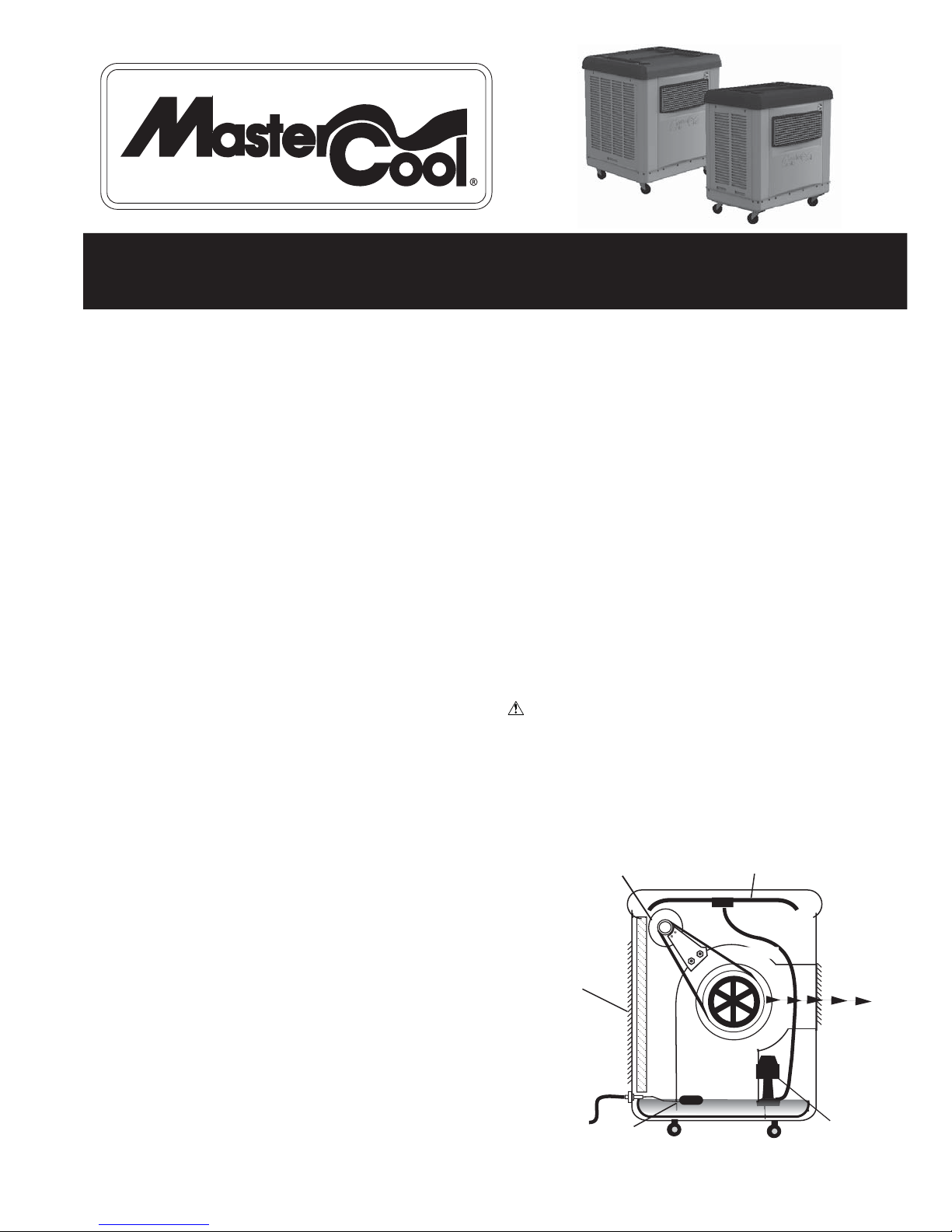
2 SPEED MOTOR
WATER-SATURATED
COOLER PADS
3 SIDES
WATER
LINE
FLOAT
WATER DISTRIBUTION HOSE
AIR FLOW
BLOWER
GRILLE
)
WATER PUMP
Page 2
COOLER ASSEMBLY
NOTE: Installation kit and manual are inside the unit.
1. Unpack unit from carton. Please recycle and discard of packing material responsibly.
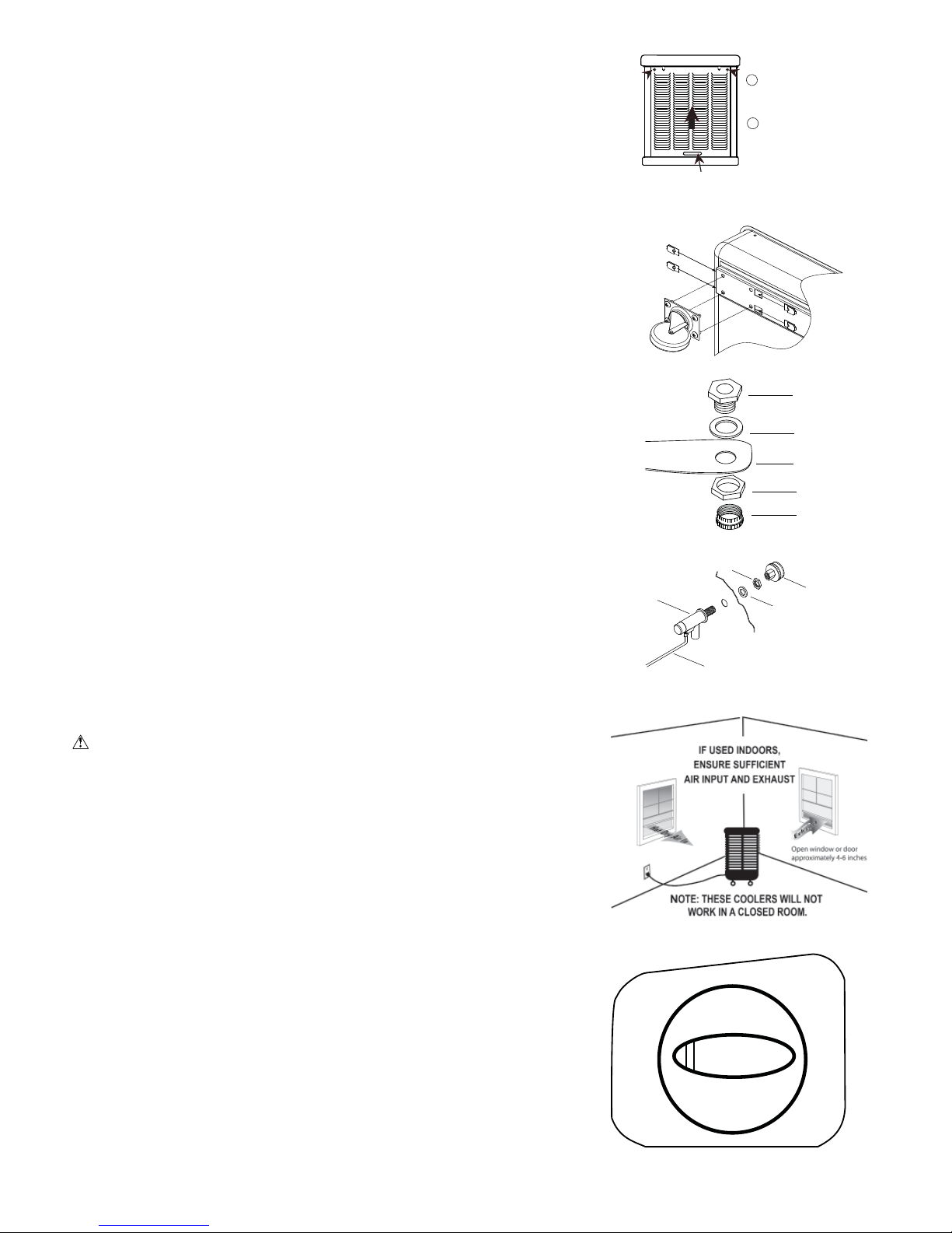
2. Two screws secure each louver panel. Locate and remove the screws about 1-1/2 inches
below the plastic work top. Replace these screws when re-installing panel.
3. Access the interior of the unit by using the handhold at the bottom of the louvered side to
lift up and out of the cabinet. Locate and remove the plastic bag of parts and manual.
CASTER INSTALLATION
NOTE: The installation kit includes (2) swivel casters with brake, (2) swivel casters
without brake, (16) tinnerman nuts and (16) 1/4-20 x 1/2 screws.
1. Place the unit on its side. Place the tinnerman nuts on the caster bracket on the bottom pan.
2. Attach the casters to the brackets with the screws provided. See illustration at right.
WATER CONNECTION
In addition to containing a large reservoir, this unit can have constant water supply via a common water hose or designated water line.
• Install drain assembly. Place the nipple through the hole in the pan, with the rubber
washer between the pan and the head of the drain nipple. Thread nut onto nipple and
draw up tight against bottom of pan. Thread the drain cap to the nipple and tighten water tigh
• Install fl oat valve. Refer to fi gure at right. Install the valve in the provided hole in the
corner post using the provided washer and nut. Install the included garden hose adapter
to the fl oat as shown if attaching a garden hose to the unit. A 1/4 inch water line may
also be used to supply a continuous amount of water to the unit.
• Fill pan with water. You may fi ll the pan manually for up to 3 hours of cooling. For auto-
matic fi lling you may attach a garden hose to the garden hose adapter or a 1/4 inch water
line to the fl oat valve.
Note: Do Not Overfi ll. Fill water to a maximum height of 2 1/2 inches (approximately 1
inch from the top of the bottom pan).
to be adjusted
to maintain this water level. This can be accomplished by bending the fl oat
If using a garden hose or water line, the fl oat will need
rod.
t.
FLOAT
HAND HOLD
REMOVE 2 SCREWS AT
1
TOP OUTSIDE OF LOUVER
PANEL
2
PUSH PANEL UP,
ANGLE BOTTOM
OUT, AND
REMOVE PANEL.
NUT
NIPPLE
RUBBER
WASHER
BOTTOM
OF COOLER
WASHER
NUT
DRAIN CAP
WATER
HOSE
CONNECTION
OPERATION
LOCATION
• When setting up the MasterCool MMBT unit in an outdoor location, take into consideration the following cautions:
CAUTIONS: Ensure power cord is secured and does not pose a tripping hazard.
Similarly, if using a water hose for constant water supply, lock unit casters, and
secure hose to reduce tripping hazard.
• If the unit is used in an enclosed area, ensure suffi cient outside air intake and
exhaust by opening windows or doors. Without a good source of outside air and an
outlet to exhaust the air, humidity will build up in the enclosed space and the unit
will not cool adequately.
CONTROLS
This unit can be used as a fan only or as an evaporative cooler. The six-position switch
allows for two speeds in fan mode (VENT), two speeds for COOL mode, a separate
PUMP position to pre-wet the pads, and an OFF position.
COOLING MODE:
1. If cooling pads are dry, place the knob in the PUMP ONLY position about 3 minutes to
allow the cooling pads to wet before turning on fan.
2. Turn the switch to either HIGH COOL or LOW COOL to start the fan in cooling mode.
NOTES: The pump will automatically turn on when the HIGH or LOW COOL position is
selected.
Use the LOW COOL setting whenever possible. This lower speed causes
the air to stay longer in the wet pads and therefore increases the cooling
effi ciency.
FAN ONLY MODE:
1. The HIGH VENT or LOW VENT positions will start the fan only, without water.
2
POWER
OFF
PUMP
ONLY
LOW
VENT
FLOAT ROD
HIGH
COOL
LOW
COOL
HIGH
VENT
110522-3
Page 3
MAINTENANCE
WARNING:
ROUTINE MAINTENANCE
WEEKLY:
1. Drain and replenish water from the cooler at least weekly. This keeps the water in the pan fresh and helps prevent scale
and mineral deposit accumulation on the pads.
AT THE END OF THE SEASON OR DURING EXTENDED PERIODS OF NON-USE:
1. Completely drain the reservoir and disconnect water supply. Ensure no water remains during freezing weather.
2. Unplug unit from power supply.
3. Cover unit or store inside when not in use.
ANNUAL MAINTENANCE
1. Change Pads. Pads should be replaced once or twice a season, depending upon the length of the season. At the beginning and at
mid season a clean pad is more absorbent and effi cient and will deliver substantially cooler air.
a. Remove louvered side.
b. Unhook the wire pad holder.
c. Replace pad (some trimming may be necessary.)
d. Reattach the wire pad holders and replace louvered sides.
NOTE: These units come with synthetic cooling pads. Although aspen pads
can be used in these coolers, we recommend using synthetic pads
pads if using indoors, to reduce the incidence of shedding.
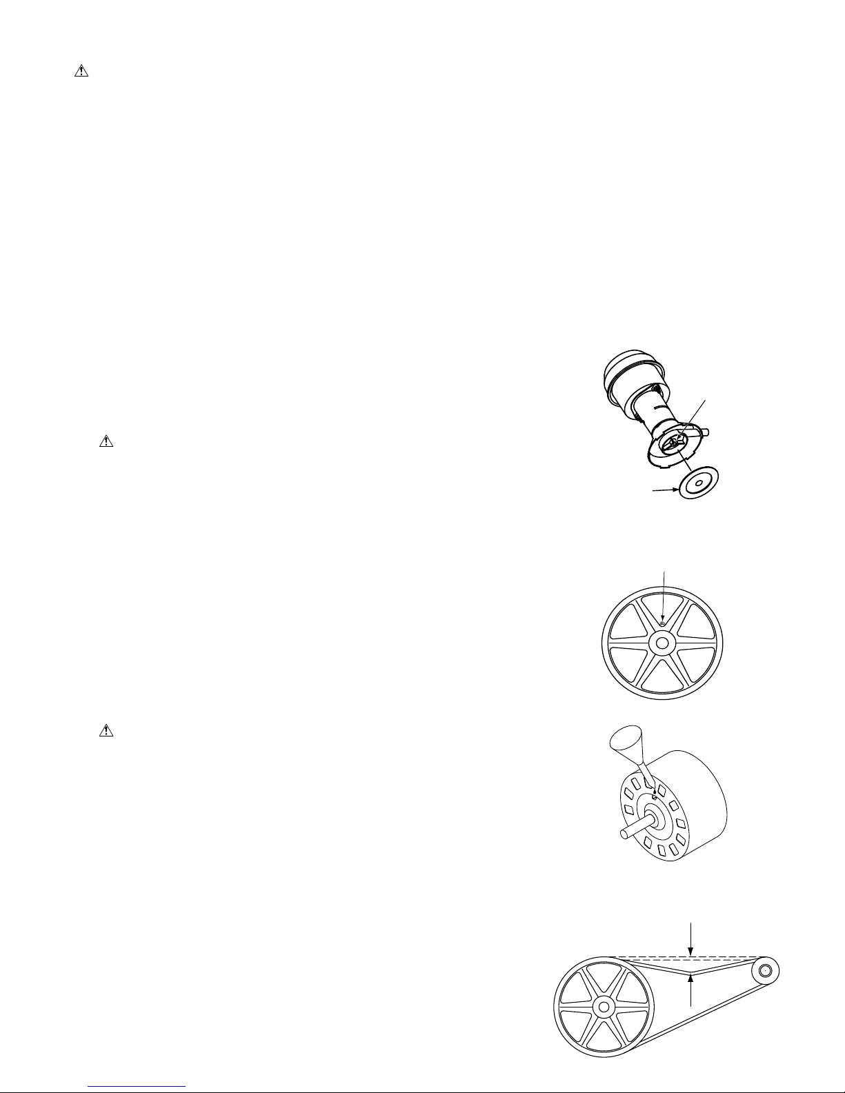
2. Clean pump. Cleaning the pump is necessary once a year at start-up.
CAUTION: Before cleaning pump, ensure unit is turned off and unit and
pump are unplugged.
a. Remove the pump from the mount slot.
b. Remove the base of the pump.
c. Clean the pump and turn the impeller to ensure free operation
d. Remove the pump spout and check for any blockage.
e. After cleaning, reinstall the base onto the pump. Press fi rmly to make sure it
is secure.
f. Reattach the pump to the mount in the cooler using the plastic retainer to
ensure that the pump will not overturn.
NOTE: Do not forget to replace the spout and water delivery tube onto the
pump outlet.
3. Oil blower bearings (MMBT14 only). The blower bearings should be oiled with a
few drops of non-detergent 20/30 weight at least oil once each year.
4. Oil motor bearing (MMBT12 only). The cooler motor in this unit should be oiled
with a few drops of non-detergent 20/30 weight oil once each year. The oil ports
are located on each side of the motor.
CAUTION: Do not over oil. Over oiling can cause motor burn out, due to
excessive oil getting into motor winding.
5. Check belt and belt tension. This applies only to model MMBT14 which is belt
driven. Model MMBT12 has a direct drive motor. Check the belt for any cracks or
wear and replace if necessary. Check the tension on the belt. A 3 lb. force should
defl ect the belt 3/4 inches. Readjust belt if needed.
Before doing any maintenance be sure power is off and unit is unplugged. This is for your safety.
over aspen
REMOVE BASE
BLOWER BEARING
IMPELLER
OIL PORT
Oil Motor
By following the operating, installation, and maintenance suggestions as outlined,
you can get many years of effi cient and satisfactory service from your cooler. In the
event additional information is desired, your dealer will be more than glad to assist
you in every possible way.
110522-3
3 LB. PRESSURE
3/4”
3
Page 4
TROUBLESHOOTING
Problem Possible Cause Remedy
Failure to start or no air delivery
1. No electrical power to unit
• Fuse blown
• Circuit breaker tripped
• Electric cord unplugged or damaged
2. Belt too loose or tight
3. Motor overheated
• Belt too tight
• Blower bearings dry
4. Motor locked
1. Check power
• Replace fuse
• Reset breaker
• Plug in cords or replace if damaged
2. Adjust belt tension
3. Determine cause of overheating
• Adjust belt tension
• Oil blower bearings
4. Replace motor
Inadequate air delivery with
cooler running
Inadequate cooling
Motor cycles on and off
Noisy
Excessive humidity in house
Musty or unpleasant odor
Water draining from cooler
1. Insuffi cient air exhaust
2. Belt too loose
3. Pads plugged
1. Inadequate exhaust in house
2. Pads not wet
• Pads plugged
• Open spots in pads
• Trough holes clogged
• Pump not working properly
1. Low voltage
2. Excessive belt tension
3. Blower shaft tight or locked
4. Bearings dry
1. Bearings dry
2. Wheel rubbing blower housing
3. Loose parts
1. Inadequate exhaust
1. Stale or stagnate water in cooler
2. Pads mildewed or clogged
3. Pads not wetting properly
• Trough holes clogged
• Pump not working properly
1. Float arm not adjusted properly
2. Drain assembly leaking
pen windows or doors to increase air fl ow
1. O
2. Adjust belt tension or replace if needed
3. Replace pads
1.
Open windows or doors to increase air fl ow
2. Check water distribution system
• Replace pads
• Repack pads
• Clean trough and unplug holes
• Replace or clean pump
1. Check voltage
2. Adjust belt tension
3. Oil or replace bearings
4. Oil bearings
1. Oil bearings
2. Inspect and realign
3. Tighten loose parts
1. Open doors or windows
1. Drain pan and clean pads
2. Replace pads
3. Check water distribution system
• Clean
• Replace or clean pump
1. Adjust fl oat
2. Tighten nut and drain cap.
SPECIFICATIONS: MMBT12
DIMENSIONS
A
REA COOLED
MOTOR SPECS.
ELECT. SPECS.
WEIGHT (LBS)
RESERVOIR
H: 34-7/8” W: 32-5/8” D: 22-1/8”
UP TO 600 SQ.FT.
1/3 HP 2 SPEED 1145 CFM
115 VOLTS 8.1 AMPS
DRY: 96 OPERATING: 162H
8 GALLONS
SPECIFICATIONS: MMBT14
DIMENSIONS
A
REA COOLED
MOTOR SPECS.
ELECT. SPECS.
WEIGHT (LBS)
RESERVOIR
H: 38-7/8” W: 35-3/16” D: 29-9/16”
UP TO 1100 SQ. FT.80
1/2 HP 2 SPEED 1600 CFM
115 VOLTSTS 10.7 AMPS
DRY: 150 OPERATING: 242G
11 GALLONS
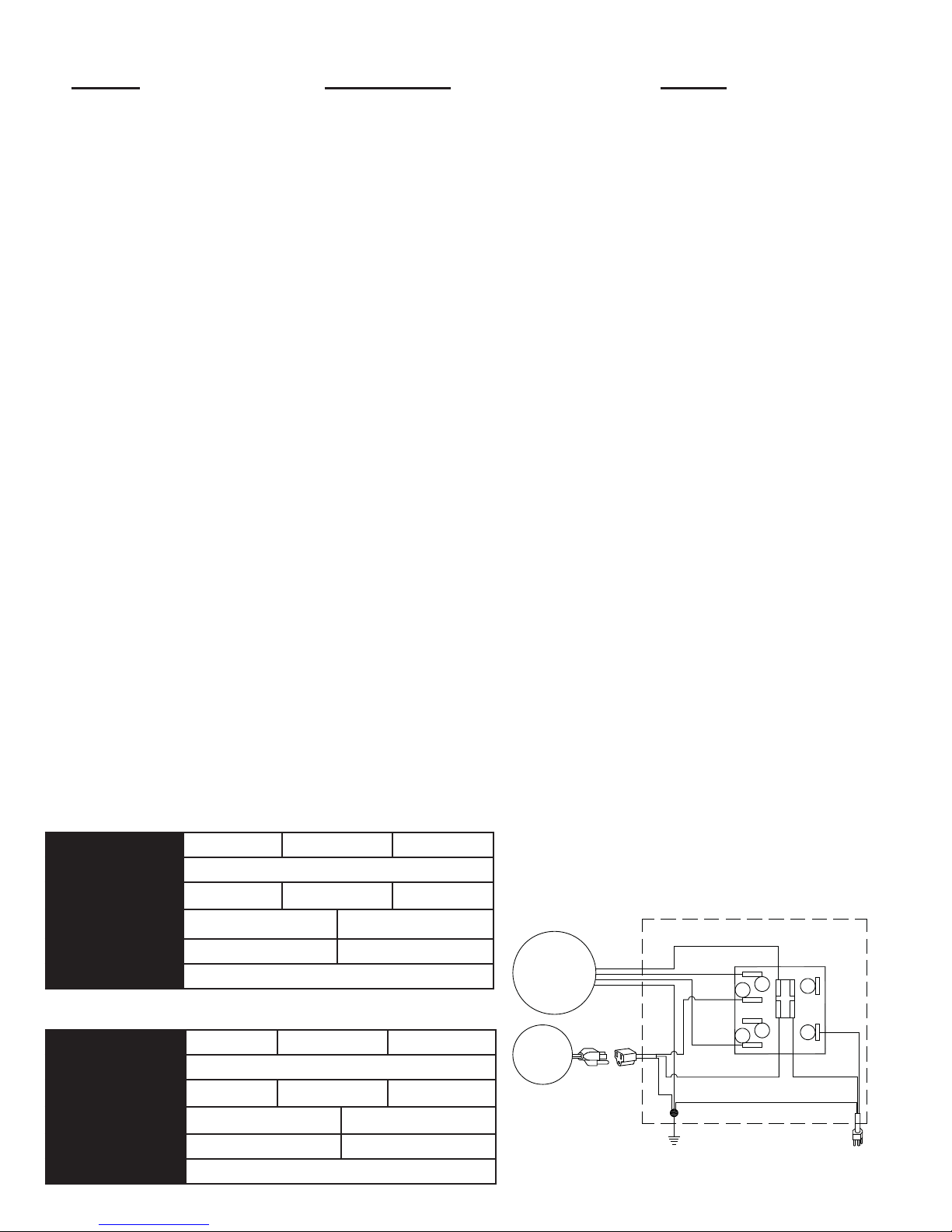
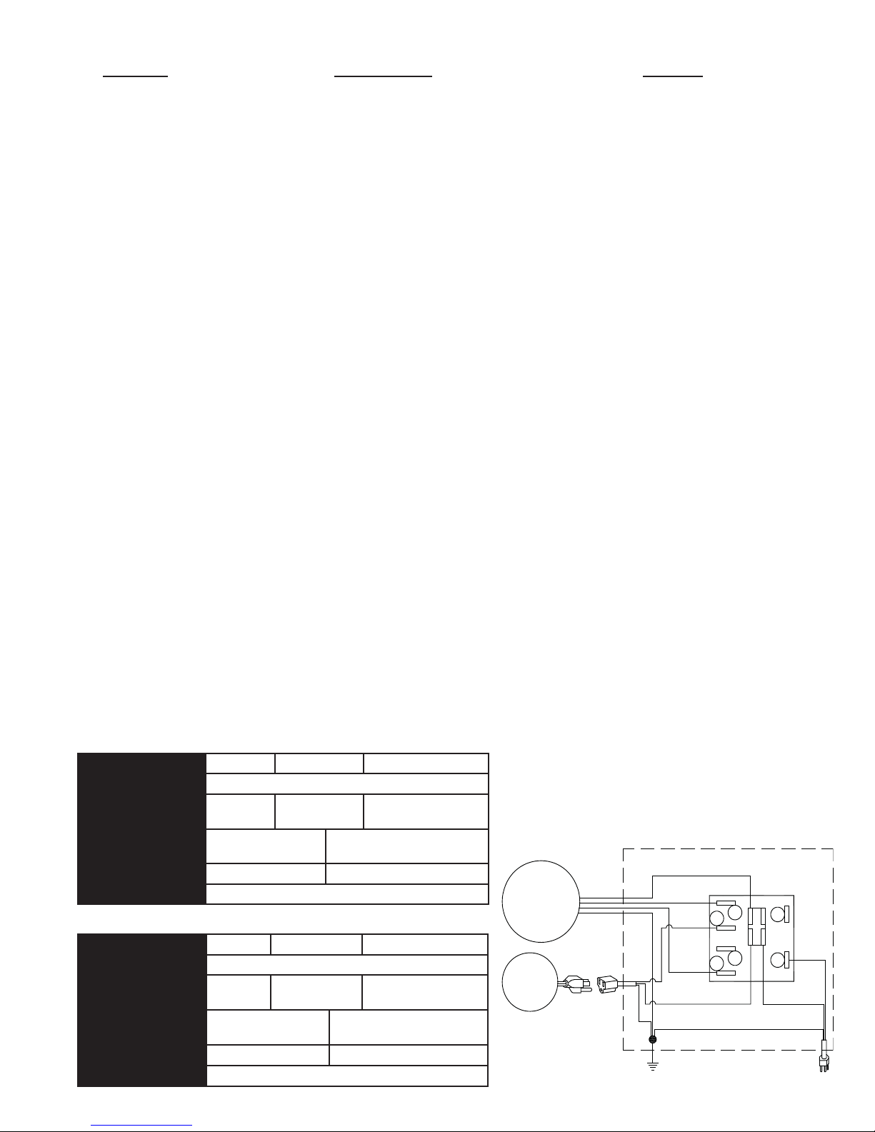
ELECTRICAL SCHEMATIC
(FOR REFERENCE ONLY)
WHITE - COMMON
4
2
SWITCH
B
PLAIN
A
RIBBED - COMMON
110522-3
GREEN
GREEN
BLACK - HIGH
BLACK
RED - LOW
WHITE - COMMON
GREEN - GROUND
3
1
BLOWER
MOTOR
PUMP
MOTOR
4
Page 5

MASTERCOOL MOBILE EVAPORATIVE COOLER
ONE YEAR LIMITED WARRANTY POLICY
SALES RECEIPT REQUIRED AS PROOF OF PURCHASE FOR ALL WARRANTY CLAIMS.
This warranty is extended only to the original purchaser of this evaporative cooler when the unit is
installed and used under normal conditions against defects in workmanship and materials as follows:
One (1) year from date of sale on the unit
The manufacturer will replace the defective part/product, at its discretion, with return freight paid
by the manufacturer. It is agreed that such replacement is the exclusive remedy available from the
manufacturer and that TO THE MAXIMUM EXTENT PERMITTED BY LAW, THE MANUFACTURER
IS NOT RESPONSIBLE FOR DAMAGES OF ANY KIND, INCLUDING INCIDENTAL AND
CONSEQUENTIAL DAMAGE OR LOSS OF PROFITS OR REVENUES.
Some states do not allow limitations on how long an implied warranty lasts, so the above limitations
may not apply to you.
Exclusions from this warranty
We are not responsible for media pads which are considered disposable and should be replaced
periodically.
We are not responsible for any incidental or consequential damage from any malfunction,
accident, misuse, alterations, unauthorized repairs, abuse, including failure to perform reasonable
maintenance, normal wear and tear, nor where the connected voltage is more than 5% above the
nameplate voltage.
Alterations include the substitution of name brand components including, but not limited to media pads.
We are not responsible for any damage from the use of water softeners or treatments, chemicals or
descaling materials.
We are not responsible for the cost of service calls to diagnose the cause of trouble, or labor charge
to repair and/or replace parts.
No employee, agent, dealer or other person is authorized to give any warranties or conditions on
behalf of the manufacturer. The customer shall be responsible for all labor costs incurred.
Some states do not allow the exclusion or limitation of incidental or consequential damages, so the
above limitations or exclusions may not apply to you.
How to obtain service under this warranty
Within the limitations of this warranty, purchaser with inoperative units should contact the dealer
where you purchased the cooler. If for any reason you are not satisfied with the response from
the dealer, contact Customer Service at 800-643-8341 for instructions on how to obtain service
within warranty as listed above.
This warranty gives the customer specifi c legal rights, and you may also have other rights which
vary from province to province, or state to state.
Register your product at www.championcooler.com.
110522-3
MASTERCOOL BY CHAMPION COOLER
5800 MURRAY ST.
LITTLE ROCK, AR. 72209
WWW.CHAMPIONCOOLER.COM
5
Page 6

MANUAL DE INSTALACIÓN Y OPERACIÓN
MÓVIL ENFRIADOR EVAPORATIVO
Encierrre con un circulo el modelo de su enfriador y
escribe el número de série.
MMBT12 MMBT14
FECHA DE COMPRA: ___________________
NÚMERO DE SÉRIE: _________________
Lea con cuidado todo este manual antes de instalar la unidad.
TABLA DE CONTENIDO
REGLAS DE SEGURIDAD ................................................6
CÓMO ENFRIAMIENTO POR
EVAPORACIÓN FUNCIONA .........................................6
CONJUNTO DEL ENFRIADOR .........................................7
OPERACIÓN ....................................................................7
MANTENIMIENTO .............................................................8
GENERAL .....................................................................8
ANUAL .........................................................................8
LA LOCALIZACIÓN DE AVERÍAS .....................................9
ESPECIFICACIONES ........................................................9
LISTA DE PIEZAS DE REPUESTO
(ENGLISH / ESPAÑOL) .............................................10-11
GARANTÍA LIMITADA ......................................................12
REGLAS DE SEGURIDAD
1. Lea las instrucciones con cuidado.
2.
La unidad debe estar Apagada y Desconectada de la electricidad cuando se instale o haga cualquier mantenimiento.
3. Su enfriador funciona sólo con corriente alterna de 120
voltios, 60 Hz. (ciclos).
El motor y la bomba están conectados con la tierra, y se
4.
apagarán automáticamente en caso de sobrecalentamiento. Los motores volverán a funcionar cuando se enfrían.
5. Enchufe una bomba del enfriador evaporativo solamente
y nada más al receptáculo de la bomba.
No haga a funcionar ningún ventilador con el cable o el
6.
enchufe dañado. Deseche el ventilador o llévelo a una instalación de servicio autorizada para revisarlo y/o repararlo.
7. No pase el cable debajo de alfombras. No cubra el cable
con tapetes, alfombras o coberturas similares. No pase
el cable debajo de los muebles o los aparatos. Coloque
el cable lejos del área de tráfi co y donde no se puede
tropezar con él.
8.
Utilice solamente en receptáculos protegidos con ICFT.
ADVERTENCIA: Para reducir el riesgo de incendio
o toques eléctricos, no use este ventilador con ningún
“dispositivo de estado sólido para controlar la velocidad
del ventilador.”
CÓMO ENFRIAMIENTO POR EVAPORACIÓN FUNCIONA
El enfriamiento por medio de evaporación es la manera de la naturaleza de refrescarse. Cuando el aire se mueve sobre una superfi cie mojada, se evapora el agua y se absorbe el calor. Al salir de
una piscina con el viento que sopla usted se siente fresco, aunque
el aire puede ser caliente. El cuerpo humano sí mismo es refrescado principalmente por la evaporación del sudor.
Este enfriador funciona usando el mismo principio. El aire se traza
a través de los fi ltros mojados donde el aire se enfría por medio de
evaporación y después circula a través del edifi cio. Se hace frío de
la sensación cuando tiene esta combinación del aire enfriado y del
movimiento del aire sobre la piel.
A diferencia de los acondicionadores de aire que recirculan el aire,
un enfriador evaporativo trae continuamente por dentro el aire fresco mientras escapa el aire viejo. Se reemplaza completamente el
aire cada 2 a 4 minutos, abriendo las ventanas o las puertas o una
combinación de ambas. El aire es siempre fresco, no es viciado,
cargado de humo y olores como ocurre con los sistemas de aire
acondicionado a base de refrigeración.
6
MOTOR DE DOS
VELOCIDADES
FILTROS
MOJADOS
3 LADOS
LÍNEA
DE AGUA
FLOTADOR
SYSTEMA DE DISTRIBUCIÓN
DE AGUA
SOPLADOR
REJA
FLUJO DE AIRE
BOMBA
110522-3
Page 7

CONJUNTO DEL ENFRIADOR
NOTA: Las ruedas y el manual se encuentran dentro de la unidad.
1. Desembale la unidad de la caja. Por favor, reciclar y desechar el material de embalaje de
manera responsable.
2. Dos tornillos fi jan cada panel. Localice y retire los tornillos que se encuentran unas 1-1/2 pulga-
das por debajo de la superfi cie de plástico. Vuelva a colocar los tornillos al volver a instalar el
panel.
3. Acceder al interior de la unidad mediante el orifi cio de la mano en la parte inferior del panel
para levantarlo arriba y fuera del gabinete. Localice y retire la bolsa de plástico de las piezas y
el manual.
INSTALAR LAS RUEDAS
NOTA: El kit de instalación contiene 2 ruedas giratorias con freno, 2 ruedas giratorias sin
freno, 16 tuercas de tinnerman y 16 tornillos.
1. Pone la unidad por su lado. Coloque las tuercas de tinnerman por el soporte del rueda como
se muestra la fi gura.
2. Coloque los ruedas al soporte con los tornillos probados.
CONECTAR
Además de contener un depósito grande, esta unidad puede tener suministro constante de agua a
través de una manguera de agua común o línea de agua designada.
1. Instale el montaje de desagüe. Quite la tuerca y pase la boquilla por el agujero de la bandeja, colocando la arandela de goma entre la bandeja y la cabeza de la boquilla. Coloque la tuerca en la boquilla y atorníllela hasta que quede apretada contra la parte inferior de la bandeja.
Atornille la tapa del desagüe a la boquilla para retener el agua.
2. Instale la válvula del fl otador. Instale la válvula en el agujero que se encuentra en el poste
de esquina usando la tuerca y arandela provistas. Si desea conectar una manguera de jardín
para un suministro continua de agua, instale el adaptador de manguera de jardín como se
muestra en la fi gura. También se puede conectar un tubo de 1/4 pulgadas.
3. Llene la bandeja con agua. Se puede llenar la unidad con agua manualmente por hasta 3
horas de aire fresco. Para llenar automáticamente conecte una manguera de jardín al adaptador o un tubo de 1/4 pulgadas al fl otador.
Nota: No Sobrellene. Llene el agua hasta una altura máxima de 2 y 1/2 pulgadas (aproximadamente una pulgada por debajo del borde superior de la bandeja). Si utiliza una manguera de jardín,
debe ajustar el fl otador para que mantenga este nivel. Esto se puede lograr doblando la varilla del
fl otador para arriba o para abajo.
EL AGUA
ORIFICIO DE MANO
FLOTADOR
QUITE LOS DOS
1
TORNILLOS DEL PANEL
2
EMPUJE HACIA ARRIBA,
GIRE LA PARTE INFERIOR
DEL PANEL AFUERA DE
LA UNIDAD, Y
REMUEVE EL PANEL.
TUERCA
ARANDELA
VARILLA DEL FLOTADOR
BOQUILLA ROSCADA
ARANDELA
DE GOMA
BANDEJA
TUERCA
TAPA DEL DESAGÜE
ADAPTADOR
PARA MANGUERA
DE JARDÍN
OPERACI
UBICAC
ÓN
IÓN
• Al usar la unidad MasterCool MMBT en una ubicación exterior, tomar en consideración los
siguientes precauciones:
PRECAUCIONES: Asegúrese de que el cable de alimentación está asegurada y no
plantea un peligro de tropiezo. Del mismo modo, si se utiliza una manguera de jardín para el
suministro de agua constante, bloquee las ruedas de la unidad, y asegure la manguera para
reducir los riesgos de tropiezos.
• Si utiliza el enfriador evaporativo en interiores, asegúrese de tener sufi ciente entrada de aire
exterior y de escape mediante la apertura de ventanas y puertas. Sin una buena fuente de aire
exterior y una salida para escapar el aire, la humedad se acumulará en el espacio encerrado y
la unidad no se enfriará adecuadamente.
LOS CONTROLES
Esta unidad se puede utilizar como sólo un ventilador o como un enfriador evaporativo.
El interruptor de seis posiciones permite dos velocidades para los modos de ventilador (VENT) y del
modo fresco (COOL), una posición de la bomba para mojar los fi ltros (PUMP ONLY), y una posición
de apagado (OFF).
MODO DE ENFRIAMIENTO:
1. Si los fi ltros están secos, coloque la perilla en la posición de “PUMP ONLY” durante unos 3
minutos para permitir que los fi ltros se mojen antes de encender el ventilador.
2. Gire el interruptor a cualquiera “HIGH COOL” (Alta Fresco) o “LOW COOL” (Bajo Fresco) para
iniciar el ventilador en modo de enfriamiento.
NOTES: La bomba se encenderá automáticamente cuando se selecciona la posición HIGH COOL o
LOW COOL. Utilice el ajuste de bajo fresco cuando sea posible. Esta menor velocidad mantiene el
aire más tiempo en los fi ltros mojados y por lo tanto aumenta la efi ciencia de enfriamiento.
MODO DE VENTILADOR SOLAMENTE:
1. Los posiciones de “HIGH VENT” o “LOW VENT” iniciará el soplador únicamente, sin agua.
APAGADO
BOMBA
SOLAMENTE
BAJO VENTILACIÓN
POWER
OFF
PUMP
ONLY
LOW
VENT
ALTA FRESCO
HIGH
COOL
LOW
COOL
HIGH
VENT
ALTA VENTILACIÓN
BAJO
FRESCO
110522-3
7
Page 8

MANTENIMIENTO
ADVERTENCIA: Antes de hacer cualquier mantenimiento, compruebe que la unidad esté apagada y desconectada de
la electricidad. Esto es por su seguridad.
MANTENIMIENTO GENERAL
SEMANALMENTE:
• Drenar y reponer el agua del enfriador al menos semanalmente. Esto mantiene el agua dulce en la bandeja y ayuda a
prevenir la acumulación de la escala y depósitos minerales en los fi ltros.
AL FIN DE LA TEMPORADA Y DURANTE PERIODOS PROLONGADOS:
• Desagüe completamente toda el agua de la unidad y desconecte el suministro de agua. Asegúrese de que no queda agua
durante el tiempo de congelación.
• Desconecte la unidad de la electricidad cuando no sea utilizada durante períodos extendidos.
• Cubra la unidad o almacénela adentro cuando no esta funcionando.
MANTENIMIENTO ANUAL
1. Cambie los fi ltros. Debe cambiar los fi ltros una o dos veces durante cada temporada, según la duración de ésta. Al principio y a
mediados de la temporada, un fi ltro limpio es más absorbente y efi ciente y producirá un mayor volumen de aire frío.
a. Quite los lados con rejillas.
b. Desenganche los soportes del fi ltro de alambre.
c. Reemplace los fi ltros (algunos recorte puede ser necesario.)
d. Vuelva a colocar los soportes del fi ltro de alambre y vuelva a instalar los lados con rejillas.
NOTA: Estas unidades vienen con fi ltros de enfriamiento sintéticos. Aunque fi ltros de
álamo se pueden utilizar en estos enfriadores, se recomienda utilizar fi ltros sintéticas en
lugar de fi ltros de álamo si se utiliza en el interior, para reducir la incidencia de verti-
miento.
2. Limpie la bomba. Es necesario limpiar la bomba una vez al principio de cada año.
PRECAUCIÓN: Antes de limpiar la bomba, compruebe que la unidad está apaga-
da y la unidad y la bomba están desenchufados.
a. Quite el sujetador de plástico de la montura y jale la bomba, deslizándola hacia
usted.
b. Quite la base de la bomba.
c. Limpie la bomba. Dé le vuelta a la hélice para verifi car que se mueve libremente.
d. Quite el pico de la bomba y vea si está obstruido.
e. Después de limpiar, reinstale la base en la bomba. Presione fi rmemente para
asegurarse de que es segura.
f. Vuelva a colocar la bomba en la unidad y fíjela en su montura con el sujetador de
plástico. Esto impedirá que se caiga la bomba al agua, lo que dañaría el motor.
NOTA: No se olvide de volver a conectar el tubo de agua a la bomba.
3. Lubrique los cojinetes del soplador (MMBT14 solamente). Los cojinetes del sopla-
dor deben aceitarse cada año con aceite no detergente de grado 20/30.
4. Lubrique los cojinetes del motor (MMBT12 solamente). El motor debe aceitarse
cada año con aceite no detergente de grado 20/30. Los puertos de aceite están situados en cada lado del motor.
PRECAUCIÓN: No lubrique demás. El agregar demasiado aceite puede ocasio-
nar que se queme el motor, a causa de un exceso de aceite entrando en los devanados
del motor.
5. Compruebe la correa y la tensión de la correa. Esto se aplica solamente al modelo
MMBT14 que tiene una correa. El modelo MMBT12 tiene motor de transmisión directa
sin correa. Compruebe el correa para saber si hay grietas o desgaste y reemplácela si
es necesario. Compruebe la tensión de la correa. Una fuerza de 3 libras debe desviar
la correa 3/4 pulgadas (véase la fi gura). Ajuste la correa si es necesario.
QUITE LA BASE
LOS COJINETES
DEL SOPLADOR
ACEITE DEL MOTOR
HÉLICE
Si usted sigue estas sugerencias en cuanto a instalación, operación y mantenimiento,
podrá disfrutar de muchos años de servicio efi ciente y satisfactorio de este enfriador.
8
3 LIBRAS
3/4 PULGADAS
110522-3
Page 9
LA LOCALIZACIÓN DE AVERÍAS
Problema Causa Posible Remedio
No arranca o no sale aire
1. No llega corriente
• Fusible fundido
• Cortacircuito desactivado
• Cable eléctrico dañado
2. Correa muy fl oja o apretada
3. Motor recalentado
• Correa muy apretada
• Cojinetes de la rueda están secos
4. Motor parado
1. Revise la corriente
• Cambie el fusible
• Restablecer el cortacircuito
• Reemplace el cable
2. Ajuste la tensión de la correa
3. Determine la causa
• Ajuste la tensión de la correa
• Lubrique los cojinetes
4. Cambie el motor
Sale poco aire cuando la
unidad está funcionando
Enfriamiento inadecuado
Motor se apaga y se enciende
Hace Ruido
Demasiada humedad en la
casa
Olor a encerrado, olor
desagradable
1. Insufi ciente abertura para que salga
el aire
2. Poca tensión en la correa
3. Filtros obstruidos
1. El agotamiento del aire es inadecuado
2. Los fi ltros no están mojados
• Filtros obstruidos
• Filtros agujereados
• Agujeros de los canales obstruidos
• Bomba no funciona
1. Voltaje defi ciente
2. Demasiada tensión en la correa
3. Eje del ventilador atorado
4. Cojinetes secos
1. Cojinetes secos
2. Rueda roza contra caja de la rueda
3. Partes sueltas
1. Insufi ciente salida de aire
1. Agua estancado en la unidad
2. Los fi ltros tienen moho o son obstruidos.
3. Los fi ltros son secos
• Agujeros del canal tapados
• Bomba no trabaja adecuada
1. Abra las ventanas o las puertas para
aumentar el fl ujo de aire
2. Ajuste la tensión o cambie la correa
3. Cambie los fi ltros
1. Abra más las ventanas o puertas
2. Revise la distribución de agua
• Cambie los fi ltros
• Acomode la paja en el fi ltro
• Límpielos
• Cámbiela o límpiela (Desconecte la unidad)
1. Compruebe el voltaje
2. Ajuste la tensión de la correa
3. Lubrique o cambie los cojinetes (Desconecte
la unidad)
4. Lubrique los cojinetes
1. Lubrique los cojinetes
2. Inspeccione y alinee (Desconecte la unidad)
3. Apriételas
1. Abra las puertas o las ventanas
1. Desagüe y limpie los fi ltros
2. Cambie los fi ltros
3. Revise la distribución de agua
• Límpielos
• Reemplace o limpie la bomba (Desconecte
la unidad)
El agua está drenando del
enfriador.
1. El fl otador no se ajusta correctamente
2. El montaje de desagüe se está
escapando
ESPECIFICACIONES: MMBT12
DIMENSIONES A: 34-7/8” L: 32-5/8” AN: 22-1/8”
ENFRIA HASTA 600 PIES CUADRADOS
ESPECIFICACIONES
DE MOTOR
ESPECIFICIONES
1/3 CV 2 VELOCIDADES
1145 PIES CUBICOS
POR MINUTO
115 VOLTIOS 8.1 AMPERAJES
ELECTRICAS
PESO (LIBRAS) SECO: 96 LLENO: 162H
RESERVOIR
8 GALÓNES
ESPECIFICACIONES: MMBT14
DIMENSIONES A:38-7/8” L: 35-3/16” AN: 29-9/16”
ENFRIA HASTA 1100 PIES CUADRADOS
ESPECIFICACIONES
DE MOTOR
ESPECIFICIONES
ELECTRICAS
PESO (LIBRAS) SECO: 150 LLENO: 242
DEPÓSITO
1/2 CV 2
VELOCIDADES
1600 PIES CUBICOS
POR MINUTO
115 VOLTIOSTS 10.7 AMPERAJES
11 GALÓNES
1. Ajuste el fl otador
2. Apriete la tuerca y la tapa de desagüe
ESQUEMA ELÉCTRICO
(SÓLO DE REFERENCIA)
BLANCO - COMÚN
VERDE
BLACK - ALTO
VERDE
ROJO- BAJO
BLANCO - COMÚ
VERDE - TIERRA
NEGRO
MOTOR DE
LA RUEDA
BOMBA
INTERRUPTOR
4
3
2
1
N
B
LISO
A
ACANALADO - COMÚN
110522-3
9
Page 10

9
8
12
14
13
7
11
10
4
6
48
MMBT12 Parts Diagram
49
46
42
45
5
41
47
24
50
43
51
25
1
27
38
40
16
39
38
3
15
2
33
34
18
35
39
28
11
30
32
36
37
7
10
9
8
13
14
12
15
26
27
24
33
23
20
18
22
19
21
7
9
8
MMBT14 Parts Diagram
35
11
39
16
7
17
38
38
39
47
43
48
44
49
9
41
42
46
3
2
34
28
1
40
10
8
11
30
31
32
45
4
5
6
50
51
10
37
36
10
110522-3
Page 11

PARTS IDENTIFICATION/ IDENTIFICACIÓN DE PIEZAS
When ordering parts, please be sure to furnish the following information on all orders. Failure to do so may delay your order. / Al
pedir piezas, incluya toda la información siguiente con su pedido. El no proporcionar toda esta información resultará en una demora.
1. Model number / El Modelo,
2. Descripton and part number / Descripción y número de pieza
3. Serial number / Número de serie
4. Date of purchase / Fecha de compra
Note: Items listed without a part number are not available for purchase and are shown for reference only.
may be purchased from your local hardware store.
Nota: Los artículos sin un número de pieza no están disponibles para la compra y se muestran sólo para referencia.
uso corriente pueden comprarse en la ferretería de su localidad.
N° Description / Descripción MMBT12 MMBT14
1. Bottom Pan / Base De La Caja...........................................................................................322175-102 322903-506
2. Top Pan / Tapa ...................................................................................................................322175-101 222905-001
3. Top Cover / Cubierta Superior De Plástico .........................................................................281049-2 281049-3
4. Blower Support Panel / Panel De Soporte Para El Soplado ..............................................222330-001 222331-001
5. Front Post, Left / Poste De Frente, Izquierda .....................................................................222323-001 222324-001
6. Front Post, Right / Poste De Frente, Derecha ....................................................................222323-002 222324-002
7. Corner Post / Poste De Esquina) .......................................................................................324018-002 (2) 324003-054 (2)
8. Louvered Side Assembly / Montaje De Reja Lateral ..........................................................324006-207 (2) 324006-206 (2)
9. Water Trough, Side / Canal De Agua, Lateral ....................................................................226004-001 (2) 226003-001 (2)
10. Media, Side / Medio Evaporativo Lateral ............................................................................110124-3 (2) 110124-5 (2)
11. Media Retainers, Side / Soportes Para El Medio Evaporativo, Lateral ..............................3PW-16 (6) 3PW-3 (6)
12. Louvered Back Assembly / Montaje De Reja Posterior ......................................................324006-208 324007-305
13. Water Trough, Back / Canal De Agua, Posterior ................................................................226004-002 226003-002
14. Media, Back / Medio Evaporativo, Posterior.......................................................................110124-4 110124-6
15. Media Retainers, Back / Soportes Para El Medio Evaporativo, Posterior ..........................3PW-15 (3) 3PW-5 (3)
16. Blower Housing / Caja Del Soplador ..................................................................................
17. Blower Housing Filler Panel / Panel De Relleno Del Caja Del Soplador ............................
18. Blower Wheel / Rueda De Soplador ...................................................................................
19. Shaft, Blower Wheel / Eje De La Rueda De Soplador........................................................- 110182
20. Bearings, Blower Wheel Shaft / Cojinetes Del Eje De La Rueda De Soplador ..................- 110351 (2)
21. Pulley, Blower Wheel / Polea Del Soplador ........................................................................- 110275
22. Drive Belt / Correa ..............................................................................................................- 110227
23. Pulley, Motor / Polea Del Motor ..........................................................................................- 110273
24. Motor Mount / Montura Del Motor.......................................................................................218109-001 (2) 314003-025
25. Motor Rail Grommet / Arandela De Goma Para La Montura Del Motor .............................110731 (4) -
26. Motor Mount Clips / Seguros Para Montar Motor ...............................................................- 314005-001
27. Motor / Motor ......................................................................................................................110441-2 110447
28. Pump / Bomba ....................................................................................................................110428 110429
30. Pump Mount / Montura De La Bomba ................................................................................222175-006 218001-031
31. Pump Retainer / Sujetador De La Bomba ..........................................................................- 1 10714
32. Tube, Water Delivery / Tubo De Agua ................................................................................310716 310716
33. Water Distributor Assembly / Sistema Del Distribuidor De Agua ........................................3D-15 3D-3
34. Holder, Water Distributor / Soporte Para El Distribuidor De Agua ......................................110574 (3) 110574 (3)
35. Drain Assembly / Montaje De Desagüe ..............................................................................3DA-1 3DA-1
36. Float Valve / Válvula De Flotador .......................................................................................FL-C FL-C
37. Garden Hose Adapter / Adaptador Para Manguera De Jardín ...........................................110824 110824
38. Swivel Caster w/ Brake / Rueda Giratoria Con Freno ........................................................110822-5 (2) 110822-5 (2)
39. Swivel Caster w/o Brake / Rueda Giratoria Sin Freno........................................................110822-2 (2) 110822-2 (2)
40. Tinnerman Nut / Tuerca Tinnerman ....................................................................................110916 (16) 110916 (16)
41. Switch Box Assembly / Ensemblaje De La Caja Para El Interruptor ....................................322334-1 322334-1
42. Switch / Interruptor .............................................................................................................110425 1 10425
43. Pump Receptacle / Tomacorriente De La Bomba ..............................................................1 10395-1 1 10395-1
44. Electrical Motor Cord / Cable Eléctrico Del Motor ..............................................................- 1 10366
45. Electrical Power Cord / Cable Eléctrico ..............................................................................110394 110394
46. Knob, Switch / Perilla Del Interruptor..................................................................................110839-006 110839-006
47. Strain Relief Bushing / Dispositivo De Alivio De Tensión ...................................................1 10736 110736
48. Front Panel / Panel Delantero ............................................................................................
49. Decal / Pegatina .................................................................................................................110543-2 1105 43-2
50.
Adjustable Vent Assembly / Montaje De La Rejilla Ajustable De Ventilador .........................110839-501 110839-501
51. Grill Trim Frame / Moldura Decorativa y Soporte De La Rejilla Ajustable ..........................310889 310889
Standard hardware items
Artículos de
110522-3
11
Page 12
MASTERCOOL ENFRIADOR MÓVIL POLÍTICA
DE GARANTÍA LIMITADA UN AÑO
PARA CUALQUIER RECLAMO RELACIONADO CON LA GARANTÍA ES
NECESARIO PRESENTAR EL RECIBO COMO PRUEBA DE COMPRA.
Esta garantía se extiende solo al comprador original de este enfriador evaporativo,
siempre y cuando la unidad sea instalada y utilizada en condiciones normales, contra
defectos de fabricación y materiales como se detalla a continuación:
Un (1) año a partir de la fecha de la venta de la unidad
El fabricante reemplazará la parte o producto defectuoso, según lo crea conveniente,
y se hará cargo de los gastos de envío de la devolución al cliente. Se acuerda que el
reemplazo es la única solución que el fabricante tiene disponible. ASIMISMO, HASTA
EL GRADO MÁXIMO PERMITIDO POR LA LEY, EL FABRICANTE NO SE HACE
RESPONSABLE POR LOS DAÑOS DE CUALQUIER TIPO, INCLUIDOS DAÑOS
INCIDENTALES Y EMERGENTES, O LA PÉRDIDA DE GANANCIAS O INGRESOS.
Algunos estados no permiten limitaciones con respecto a cuánto tiempo dura una
garantía implícita, por lo tanto es posible que las limitaciones detalladas anteriormente
no se apliquen a usted.
Exclusiones de esta garantía
No nos responsabilizamos por las almohadillas, que se consideran desechables y deben
reemplazarse periódicamente.
No nos responsabilizamos por cualquier tipo de daños accidentales o resultantes,
producto de cualquier tipo de mal funcionamiento, accidente, mal uso, alteraciones,
reparaciones no autorizadas, abuso, incluidos la falta de mantenimiento razonable, uso
o desgaste normal, ni en situaciones donde el voltaje conectado sea un 5% mayor al
indicado por la placa indicadora.
Las alteraciones que puede sufrir el producto incluyen la sustitución de componentes de
marca, incluido, pero no limitado almohadillas del medio.
No nos responsabilizamos por cualquier daño provocado por el uso de suavizantes o
tratamientos de agua, químicos o materiales de descalcifi cación.
No nos responsabilizamos por el costo de las llamadas al servicio para diagnosticar la
causa del problema o el cargo de la mano de obra para reparar o reemplazar piezas.
Los empleados, agentes, distribuidores u otras personas no se encuentran autorizados
a brindar garantías o condiciones en nombre del fabricante. El cliente será responsable
por todos los costos de mano de obra incurridos.
Algunos estados no permiten la exclusión o la limitación de daños incidentales o
resultantes, por lo tanto es posible que las limitaciones o exclusiones detalladas
anteriormente no se apliquen a usted.
Cómo obtener servicio bajo esta garantía
Dentro de las limitaciones de la presente garantía, el comprador que tanga unidades
fuera de funcionamiento debe comunicarse con el servicio de atención al cliente al 800-
643-8341 para obtener instrucciones sobre cómo obtener las piezas de repuesto dentro
de la garantía, como se indica anteriormente.
Esta garantía le confi ere al cliente derechos específi cos. Además, el cliente puede gozar
de otros derechos que varían según la provincia o el estado.
Registre su producto en www.championcooler.com.
MASTERCOOL BY CHAMPION COOLER
5800 MURRAY ST.
LITTLE ROCK, AR. 72209
WWW.CHAMPIONCOOLER.COM
12
110522-3
 Loading...