

Page 1
72968-R11.16
Page 2

MasterCool® MCP Series Evaporative Window Cooler
Installation and Operating Manual
Congratulations on your purchase of the MasterCool® MCP Series plastic evaporative cooler. This unit is manufactured with
the intent of off ering you years of reliable, effi cient cooling.
NOTE: READ THESE INSTRUCTIONS BEFORE INSTALLING THE COOLER. Follow the installation instructions in
this manual carefully. Varying from them may create safety concerns and will void the warranty.
Safety Instructions
1. Use only with 110V 60 Hz single phase grounded outlet.
2. Ensure cooler is turned OFF and UNPLUGGED before installing, servicing or cleaning the unit.
3 . Do not operate unit with damaged cord or plug, or with any other damaged or missing parts.
4 . Do not run cord under carpeting. Do not cover cord with throw rugs, runners, or similar coverings.
Do not route cord under furniture or appliances. Arrange cord away from traffi c area and where it will not be tripped over.
5. Do not operate cooler with the rear media guard removed.
6. Do not use an extension cord to operate cooler.
7. Do not use an adapter to convert the three pin connector for use in an ungrounded 2 prong outlet.
8. Do not use with a solid state speed control device. Violation of this could cause fi re or electrical shock.
9. Do not alter or modify this cooler.
10. Repairs or replacement of electrical components should only be carried out by qualifi ed electricians.
11. Do not allow children to install, service, or operate the cooler.
12. This fan cannot be used as an exhaust fan in a kitchen, and must be a minimum of 3 feet from open fl ame.
Table of Contents
Safety Instructions ........................................................................................................................................................ 2
Note About Evaporative Coolers .................................................................................................................................... 3
Features of the MasterCool
Before Installing ............................................................................................................................................................. 4
Required Clearances/specifi cations .............................................................................................................................. 4
Cooler Assembly ........................................................................................................................................................... 4
Installation Procedures
Installation in Window ............................................................................................................................................... 5
Installation in Wall ..................................................................................................................................................... 5
Water Connections ......................................................................................................................................................... 6
Water Pump .............................................................................................................................................................. 6
Overfl ow Drain ......................................................................................................................................................... 6
Float Connection ....................................................................................................................................................... 6
Water Source Connection ......................................................................................................................................... 6
Option 1 ................................................................................................................................................................ 6
Option 2 ................................................................................................................................................................ 6
Closing up Cooler........................................................................................................................................................... 7
Electrical System ............................................................................................................................................................ 7
Operating Instructions .................................................................................................................................................... 7
Optional Installations / Accessories ................................................................................................................................ 8
Optional Purge Pump ................................................................................................................................................ 8
Programming Purge Pump ...................................................................................................................................... 9
Optional Plug-in Thermostat Usage .................................................................................................................... 9
Servicing Instructions .....................................................................................................................................................10
Annual Maintenance ................................................................................................................................................10
Winterization ...........................................................................................................................................................12
Troubleshooting ..............................................................................................................................................................12
Cooler Diagram and Parts List ......................................................................................................................................13
Warranty ........................................................................................................................................................................14
Español Manual… ..........................................................................................................................................................15
®
MCP Series Window Cooler ........................................................................................... 3
2
Page 3
BEFORE INSTALLING
WARNING: Do not connect electrical power to the unit
until the installation is completed.
The MasterCool MCP Series cooler can be installed in a
sash-style or a slider-style window.
Alternatively, this unit is approved for in-wall installations.
REQUIRED CLEARANCES/ SPECIFICATIONS:
In all installations, the following clearances are required:
• Width: 22”
• Height: 22” PLUS: 4” additional space required above
exterior of cabinet for maintenance.
• Weight: 93 lbs operating weight.
Tools & Materials Required: (Not supplied)
• Drill (power or cordless)
• Assorted drill bits (for drilling pilot holes for mounting
hardware)
• Adjustable Wrench
• Phillips Head Screwdriver
• Silicone or all-weather caulk for sealing closeout panels
to window frame
• Bubble level ( 3 foot level is preferred)
• Spacer material (as required)
Water connection Option 1
• Standard water hose
Water connection Option 2
• Sill-cock valve
• Length of ¼” copper or plastic tubing
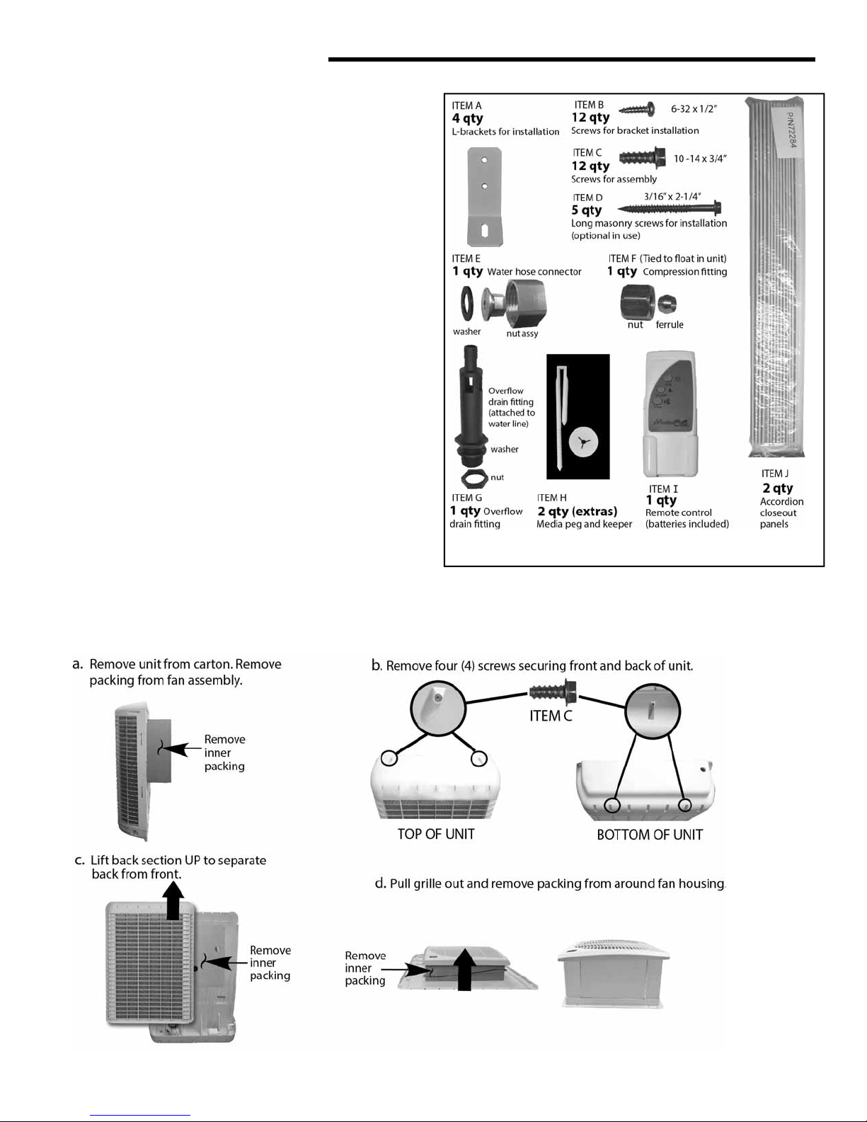
Cooler Assembly
1. Remove unit from box. Verify that all parts are included.
2. Remove all packing materials, as shown below.
Parts
CALL 1-800-643-8341 IF YOU FIND PARTS
MISSING OR HAVE ANY QUESTIONS.If If
CALL 1-800-643-8341 IF YOU FIND PARTS
MISSING OR HAVE ANY QUESTIONS.
4
Page 4
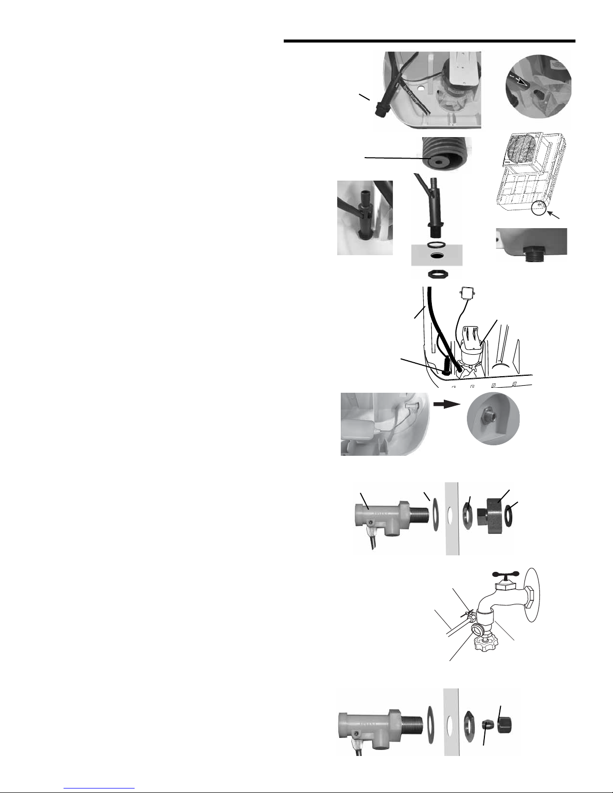
WATER CONNECTIONS
(see illustrations at right)
The cooler operates by water being pumped from the bottom pan
through a water distribution system to saturate cellulose media pads.
water lines are snapped into plastic keepers along the inside of
The
the unit.
Water Pump
A self-contained water pump continuously circulates water through
black plastic lines to a distribution tray in the top of the cooler that
percolates water over the media.
1. The pump and water lines are shipped disconnected.
2. The overfl ow drain (ITEM G) is attached to the drain line and
should be pushed down to be fl ush with the end of the drain tube.
3. Push the other portion of water line onto the intake port on the pump
Overfl ow Drain
4. Remove the nut on the end of the drain and insert the fi tting
through the hole in the cooler bottom. Then tighten the nut on
the bottom of the cooler.
5. Make sure the rubber washer (installed inside reservoir) does
not twist while tightening, which could cause it to leak. DO
NOT OVER TIGHTEN.
6. If leakage occurs after reservoir is full, re-tighten the overfl ow
fi tting until leaking stops.
7. A standard water hose can be attached to exterior portion of
the overfl ow drain fi tting to
Float Connection
The fl oat has been installed in bottom of the cooler with ferrule and
compression nut zipped tied to the fl oat. Cut these free for use
(as described below) with water line installation. The fl oat level is
factory set to maintain 2 inches of water in the reservoir. After installation is complete the fl oat might need readjustment by slightly
bending the fl oat arm.
Water Source Connection
Steady water supply is required for operation of the cooler. If taking
water from an external faucet, there are two options for attaching
water to the cooler.
Option 1:
If using a standard water hose to supply water:
1. Install the fl oat and red gasket on the inside of the cooler,
securing them with the threaded jam nut on the outside of
the cooler.
2. On the exterior, screw the small nut inside the water hose
connector onto the threaded fl oat valve port. Can use a
14mm wrench to tighten. DO NOT OVERTIGHTEN.
3. Screw a standard water hose into the connector. Verify washer is in place.
4. Leave water spigot turned off until installation is complete.
Option 2:
A more permanent supply of water can be installed from an outside
water faucet by installing a sill-cock and 1/4" water line to supply
continuously to the cooler.
1. Install a sill-cock (locally available) onto the faucet.
2. Determine length of water line needed and install one end of
1/4" plastic or copper line on sill-cock and use the ferrule and
nut (zip-tied to the fl oat for packing) to connect the water line
to the fl oat valve attach point.
6
1.
OVERFLOW
DRAIN
2.
DRAIN LINE FLUSH
WITH OVERFLOW
DRAIN
4.
.
VIEW FROM TOP
OVERBOARD
DRAIN
FLOAT VALVE
3.
OVERFLOW
DRAIN
5.
WASHER
COOLER
BOTTOM
NUT
6.
TO WATER
DISTRIBUTION
FLOAT VALVE
WATER LINE
ATTACH POINT
INTERIOR
OPTION 1
GASKET
OPTION 2
SHUT OFF VALVE
PLASTIC OR
COPPER LINE
TO COOLER
STD. HOSE CONNECTION
INTERIOR EXTERIOR
WATER PUMP
EXTERIOR
JAM
NUT
FERRULE
WATER HOSE
CONNECTOR
COMPRESSION NUT
VIEW FROM
BOTTOM
WASHER
TO
STANDARD
WATER
HOSE
SILL-COCK
TO 1/4"
WATER LINE
LOCATION
OF DRAIN
Page 5
P
Remote Control
The remote control supplied with this cooler allows you to turn the unit on or off , control
fan speed and initiate the pump. The buttons operate in the same manner as those on the
front control panel. The remote control’s range is approximately 20 feet within sight of the
cooler. Two AA alkaline batteries are included. Remove the guard between the batteries to
activate the remote. It is now ready for use. A wall mountable holder is also supplied with
the remote.
OPTIONAL ACCESSORIES
Optional Purge Pump
In addition to the standard water pump to recirculate water
from the reservoir, an optional purge pump can be installed to
evacuate the contents of the reservoir on a scheduled basis.
The cooler base has space and pre-located screw attach points
for purge pump bracket.
CAUTION: The MCP44-PPK purge pump kit is designed to be
used with the MCP series coolers. If a diff erent purge pump is
installed the warranty cooler will be voided.
The MCP44-PPK is available for purchase at local retailers, at
www. championcooler.com or by calling
1.800.643.8341.
When a purge pump has been installed, purge cycles can be
activated and programmed from the control panel (See below)
The use of the purge pump saves water and is actually more
economical, than continual bleed.
growth and mineral buildup extending media life.
fresher air in the home.
Purge Pump Discharge: The water ejected at the time of
purging will be expelled at a high rate of speed, and must be
routed away from the foundation of the home or other areas
where rushing water could do damage.
1. Attach a standard water hose to the overfl ow drain to
direct the water away from the house.
NOTE: This water is not potable, but can be used for watering
vegetable or fl ower gardens.
.
UNIT POWER ON/OFF
PUMP ON/OFF
ON
FAN SPEED (1-3)
PUMP
FAN
It helps reduce bacterial
It also maintains
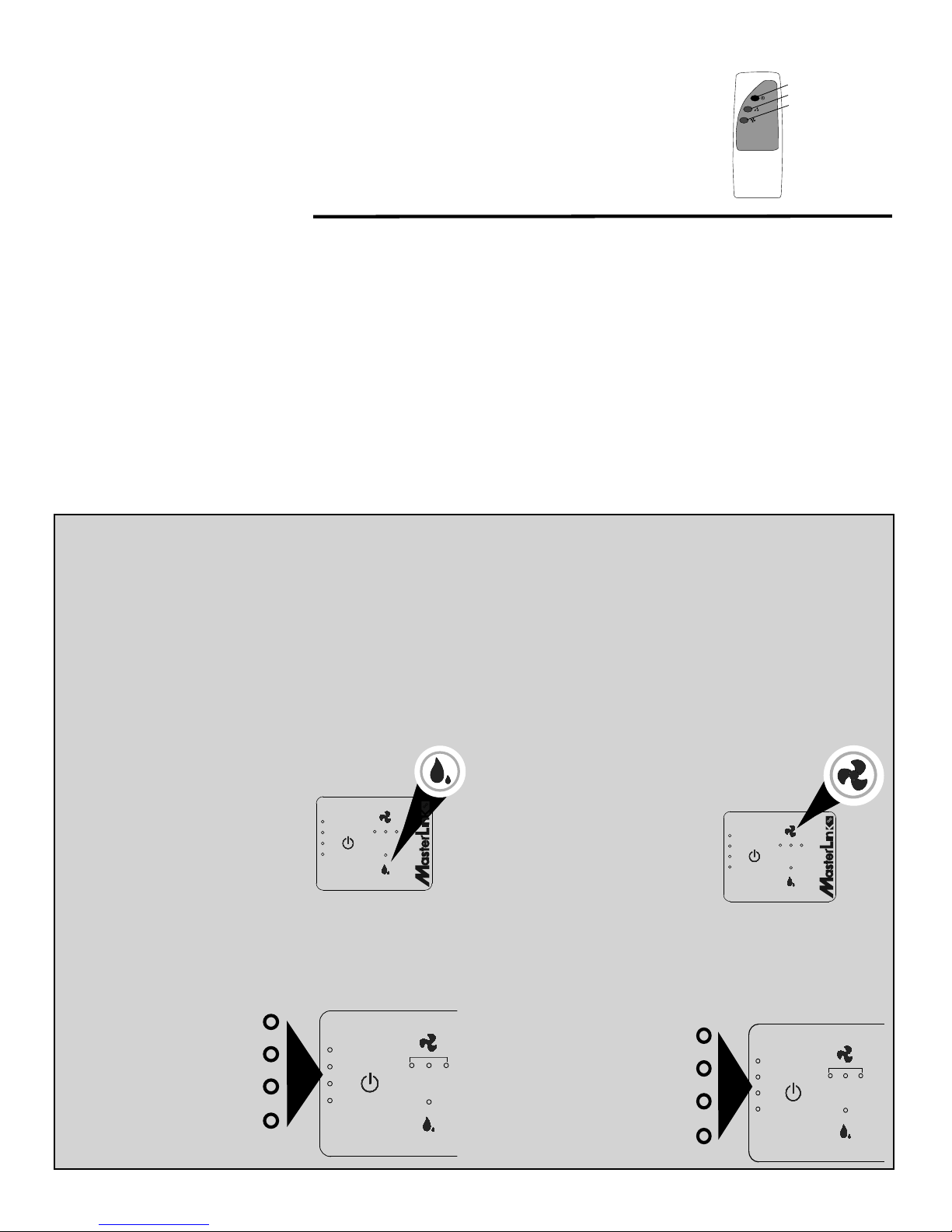
PROGRAMMING PURGE PUMP
NOTE: When in Purge Set Up Mode, you will not aff ect the fan speed or main water pump operation.
Once a purge pump has been installed and plugged
into the cooler, the purging cycle can be programmed
from the control panel:
The default setting for the purge pump is 1 minute of
purge every 24 hours. This setting can be changed to
increase interval and duration of purges as needed.
order to enter the programming
In
panel hold down the PUMP touch
point for fi ve (5) seconds.
At this point the Purge Interval
can be set. Four lights on the left
side illuminate.
This indicates one
mode of the control
PRESS AND
HOLD 5
SECONDS
FAN
PUM
purge every 24 hours.
HI
M
To change the number of hours
POWER
ED LO
between purges, press PUMP
again until the desired schedule
PUMP
is selected. The options for purge
interval are 24,12, 8 and 6 hours. The lights decrease
by one each time the Pump button is pressed. Note
the legend of intervals listed below.
4 LIGHTS = EVERY 24 HOURS
3 LIGHTS = EVERY 12 HOURS
2 LIGHTS = EVERY 8 HOURS
POWER
1 LIGHT = EVERY 6 HOURS
HI
FAN
M
PUMP
ED LO
NOTE: Depending on the amount of minerals in
the local water, it may be advantageous to increase the purges to extend the life of the media
and the unit.
After the number of hours in the Purge Interval has
been set, you may select the duration of the purge.
Options are from 1 to 4 minutes that the water will be
expelled.
Press the FAN touch point
POWER
PRESS TO
SET PURGE
DURATION
FAN
HI
M
ED LO
PUMP
to enter the Purge Duration
setting feature.
The four lights on the left side
will begin blinking indicating 4
minutes of purging. Press the
PUMP touch point to change
the setting from 4 to 3 minutes,
then 2 or 1 minute duration.
To save and exit the Duration portion of the programming
press and hold the FAN touch point for 5 seconds.
NOTE: If no touch-point is pressed within 10 seconds, the program will automatically exit the set up
mode and retain previous settings.
4 LIGHTS BLINKING = 4 MINUTES
3 LIGHTS BLINKING = 3 MINUTES
2 LIGHTS BLINKING = 2 MINUTES
1 LIGHT BLINKING = 1 MINUTE
POWER
HI
FAN
FAN
M
ED LO
PUMP
,
8
Page 6

Annual Maintenance (Con’t)
Water Distributor
1. Inspect the water distribution section to ensure all orifi ces
are clear.
2. Verify the hose connections are in good order and no
kinks or tears are present.
Water Drain Overfl ow
3. On the bottom of the cooler, unscrew the plastic nut holding the overfl ow drain in place. Push the drain up into the
cooler base to allow rapid draining. Check the condition
of the gasket at the bottom of the fi xture. When reinstalling, ensure the standpipe fi xture is secure and there is no
leakage after the reservoir is fi lled.
NOTE: If during usage of the cooler you start noticing low saturation of pads and insuffi cient cooling, or
leakage from the cooler, check the gasket at the base
of the standpipe. This is the most likely cause of leakage on this unit.
Optional Water Purge Pump (if installed)
4. If a purge pump has been installed on the MCP Series,
check that the purge pump and strainer are corrosion-free with freely moving parts.
WATER
DISTRIBUTOR
OPTIONAL
PURGE PUMP
(OWNER INSTALLED)
Media Pad Replacement
5. When the media pads have become encased with mineral buildup, broken or damaged, replace them with Genuine Munters GreenGuard Celdek
model MCP44-PAD. You may purchase them on-line at
www.championcooler.com or by calling 1.800. 643.8341.
®
replacement pads,
Winterization
The MCP Series cooler is durable enough to be left installed
during the winter, though a few precautions must be taken to
ensure no water freezes in the unit or lines.
If the temperatures in your area drop well below freezing it
may be wise to remove the water supply line from the
outside faucet.
Draining
1. Turn off and unplug cooler.
2. Turn the water supply to the cooler off .
3. On the bottom of the cooler, unscrew the plastic nut holding the overfl ow drain in place. Push the drain up into the
cooler base to allow rapid draining.
4. Remove 4 screws securing the back media guard, lift up
and remove . Access interior of unit.
5. Soak up any remaining water and ensure all water is
drained from both the water pump and purge pump
(if installed).
6. Disconnect and drain the water hoses and water
distributor.
7. Replace the media guard with four screws
Covering
1. An optional weatherproof exterior fi tted cover, model
MCP44-EC is available for purchase on line at www.
championcooler.com, at retail outlets or by calling
1.800.643.8341.
a. Use the elastic corners and straps to secure the
cover onto the back of the unit.
2. An optional interior grille cover, model MCP44-IC
(Included with MCP44E) to keep air from entering the
home through the window is available at www.championcooler.com, a retail outlet or by calling 1.800.643.8341.
a. Use the snap on clips molded into the cover to
secure the cover to the grille.
10
Page 7
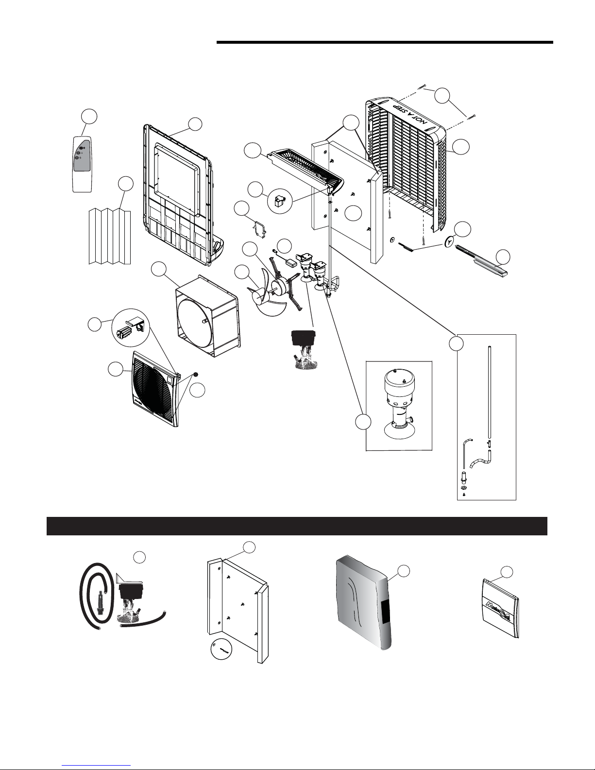
COOLER PARTS DIAGRAM
2
ON
PUMP
FAN
CHAMPION / ESSICK AIR
21
19
(2 ea.)
17
20
16
12
18
(4 ea.)
13
15
5
6
14
11
(OPTIONAL
OWNER INSTALLED
PURGE PUMP)
4
3
MCP SERIES COOLER
(1 pump)
1
7
8
10
22
PURGE PUMP KIT
OPTIONAL ACCESSORIES
23
Kit includes full set
of media, pegs
and keepers
PAD REPLACEMENT KIT
9
EXTERIOR COVER
24
25
INTERIOR COVER
12
Page 8

MASTERCOOL MCP SERIES COOLER
ONE YEAR LIMITED WARRANTY
SALES RECEIPT REQUIRED AS PROOF OF PURCHASE FOR ALL WARRANTY CLAIMS.
This warranty is extended only to the original purchaser of this evapora ve cooler when the unit is installed and used under
normal condi ons against defects in workmanship and materials as follows:
• One (1) year from date of sale on the unit, and
• Five (5) years on the evapora ve media, which is considered a disposable component and should be replaced
periodically, and
• Two (2) years on motor.
The manufacturer will replace the defec ve part/product, at its discre on, with return freight paid by the manufacturer. It is
agreed that such replacement is the exclusive remedy available from the manufacturer and that TO THE MAXIMUM EXTENT
PERMITTED BY LAW, THE MANUFACTURER IS NOT RESPONSIBLE FOR DAMAGES OF ANY KIND, INCLUDING INCIDENTAL AND
CONSEQUENTIAL DAMAGE OR LOSS OF PROFITS OR REVENUES.
Some states do not allow limita ons on how long an implied warranty lasts, so the above limita ons may not apply to you.
Exclusions from this warranty
We are not responsible for any incidental or consequen al damage from any malfunc on, accident, misuse, altera ons,
unauthorized repairs, abuse, including failure to perform reasonable maintenance, normal wear and tear, nor where the
connected voltage is more than 5% above the nameplate voltage.
Altera ons include the subs tu on of name brand components including, but not limited to media pads.
We are not responsible for any damage from the use of water so eners or treatments, chemicals or descaling materials.
We are not responsible for the cost of service calls to diagnose the cause of trouble, or labor charge to repair and/or replace
parts.
No employee, agent, dealer or other person is authorized to give any warran es or condi ons on behalf of the manufacturer.
The customer shall be responsible for all labor costs incurred.
Some states do not allow the exclusion or limita on of incidental or consequen al damages, so the above limita ons or
exclusions may not apply to you.
How to obtain service under this warranty
Within the limita ons of this warranty, purchaser with inopera ve units should contact the dealer where you purchased the
cooler. If for any reason you are not sa sfi ed with the response from the dealer, contact Customer Service at 800-643-8341
for instruc ons on how to obtain service within warranty as listed above.
This warranty gives the customer specifi c legal rights, and you may also have other rights which vary from province to
province, or state to state.
Register your product at www.championcooler.com.
MasterCool® by Champion Cooler
5800 Murray St.
Little Rock, AR 72209
800.643.8341
www.championcooler.com
14
Page 9
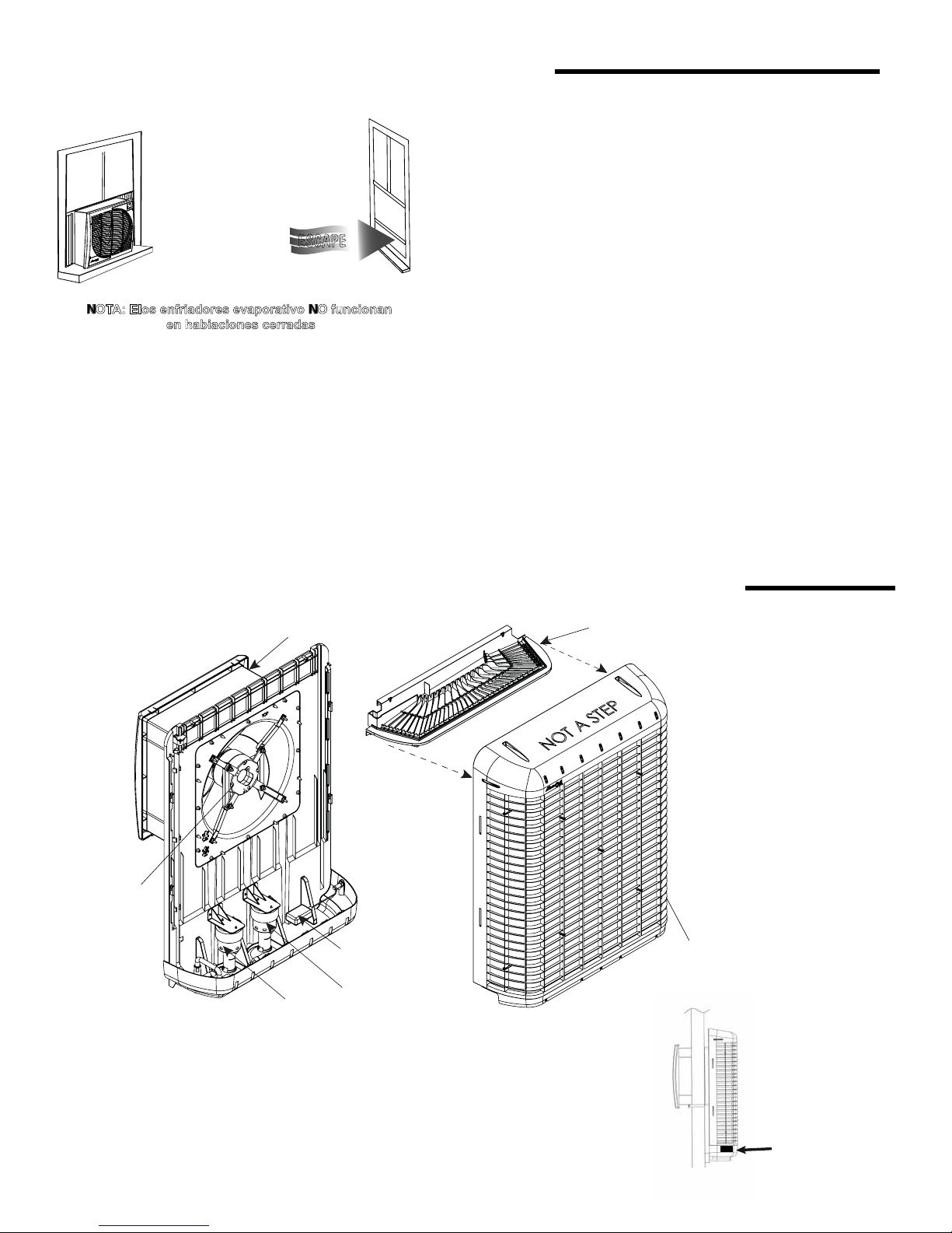
NOTA ACERCA DE LOS ENFRIADORES EVAPORATIVO
Ó
Para enfridaor trabajar mejor, tiene que
haber una vnetana o puerta abierta
en cada habitacion donde
el enfriamiento
es deseado.
ESCAPE
Ventana o puerta
abierta 4-6 pulgades
NOTA: Elos enfriadores evaporativo NO funcionan
en habiaciones cerradas
Purga de agua:
Los enfriadores evaporativo requieren un suministro de agua
continuo para mantener saturado el medio y lograr un máximo
enfriamiento. Debe retirarse de la unidad el agua bombeada
dentro del enfriador para evitar la acumulación de minerales
y bacterias. Esto puede suceder por acción gravitatoria de
un fl ujo de descarga constante o por un sistema de purga
programado a través de una bomba. . La bomba de purga
(MCP44-PPK) está disponible en www.championcooler.com
o llamando al 1.800.643.8341.Consulte las páginas 21 y 22
para obtener más detalles acerca del funcionamiento de la
bomba de purga.
Ventilación:
A diferencia de los acondicionadores de aire, los enfriadores
evaporativo necesitan un sistema de ventilación abierto y no
cerrado.
Se requieren tanto una fuente de aire fresco como una apertura de escape para generar una correcta circulación de aire.
En general, una ventana o puerta parcialmente abierta en
cada habitación donde se desea enfriamiento creará el fl ujo
de aire adecuado para una efectividad óptima de un enfriador
por evaporación. De manera alternativa, los conductos de
ventilación del ático como UP-DUX® se pueden instalar para
proporcionar un movimiento de aire sufi ciente sin necesidad
de ventanas abiertas.
NOTA: Para mejores resultados, las ventanas/puertas
abiertas no deben estar en la parte de la casa enfrentada al viento.
ADVERTENCIA: El agua expulsada del enfriador debe
dirigirse lejos de cualquier área que pudiera afectar
los cimientos u otras zonas vulnerables.
NOTA: Los dibujos de este manual son para fi nes
ilustrativos y pueden refl ejar pequeñas diferencias en
función de las diferencias de diseño y confi guración.
FUNCIONES DEL ENFRIADOR DE VENTANA MASTERCOOL® MCP SERIE
CARCASA DEL VENTILADOR
C/ FRENTE DESMONTABLE
MOTOR DEL
VENTILADOR
FLOTADOR
OPCIONAL
BOMBA DE AGUA
BOMBA DE PURGA
La carcasa y la estructura de este enfriador están realizados
en un plástico reforzado y resistente a los rayos UV, lo que da
como resultado un enfriador liviano y de fácil instalación. La
unidad está construida en dos secciones básicas para posibilitar una rápida instalación dentro de ventanas a guillotina o
corredizas.
El medio rígido de altísima efi ciencia brinda un enfriamiento
superior, comparado con otros enfriadores a evaporación.
BANDEJA DE DISTRIBUCI
DE AGUA
NOTA: Antes de insta-
lar la unidad, tómese
un momento para
anotar el número de
serie y escribirlo en la
cubierta del manual en
el espacio provisto.
16
N
SECCIÓN EXTERIOR/
PROTECCIÓN DEL MEDIO
EL NÚMERO DE SERIE
SE ENCUENTRA EN EL
LADO DERECHO DEL
ENFRIADOR
Page 10

PROCEDIMIENTOS DE INSTALACIÓN (consulte las ilustracio-
nes de la derecha)
Carcasa del ventilador segura
1. En la sección frontal, extienda la carcasa del ventilador completamente desde el armazón.
2. Utilice 12 tornillos (ARTÍCULO C) para asegurar el módulo del
ventilador en el lugar.
Instalación en la ventana
NOTA: Recomendamos dos personas para la instalación.
1. Extraiga la pantalla (según sea necesario) y asegúrese de que
la ventana esté abierta en toda su altura. Desde el exterior de la
ventana, deslice la parte del módulo del ventilador en la ventana.
Asegúrese de que la persona que esté en el interior ajuste la colocación exacta de la unidad para mantener el aspecto y las longitudes
correctas de los dos separadores de acordeón (incluidos).
Nota: Después de identifi car la posición de la instalación, coloque
un nivel de
de la unidad y realice los ajustes necesarios para asegurarse de
que la unidad esté nivelada cuando se haya completado la instalación.
distintos puntos durante la instalación.
Parte exterior
2. Cierre la ventana para ayudar a sostener la unidad en posición durante los siguientes pasos. Empuje la unidad dentro de la ventana hasta
que el montaje del ventilador esté completamente en la apertura de la
ventana. El borde del montaje del ventilador debe estar posicionado
fuera de la ventana. El ancho del borde generalmente requerirá el uso
de un espaciador (no suministrado) en la parte inferior del enfriador
con el fi n de garantizar una instalación en escuadra. Utilice dos (2)
tornillos de mampostería (ARTÍCULO D) u otros sujetadores para
asegurar la unidad en la estructura externa.
Parte interior
3. Cuatro soportes en L (ARTÍCULO A) se suministran para asegurar
el enfriador a la estructura de la ventana. La instalación recomendada usa dos soportes para asegurar la unidad en la parte superior y
dos para asegurarla al antepecho de ventana. Sin embargo, puede
confi gurar su instalación según sea necesario siempre que haya
cuatro puntos de ajuste seguros.
NOTA: Para una instalación fácil, existen ranuras en la parte inferior de la carcasa del ventilador que se ajustan a los soportes.
4. Compruebe que el módulo esté fi jo para evitar vibraciones entre las
secciones frontal y posterior.
5. Sujete los paneles de cierre de acordeón (ARTÍCULO J). Para ello,
despegue las cintas adhesivas y sujete un lado en la cubierta de la
ventana y el otro lado en el montaje del ventilador. Pueden utilizarse tornillos cortos (no incluidos) para obtener una instalación más
segura. (Cerciórese de que los tornillos no interfi eran con las aspas
del ventilador.)
6. Una vez instalados los separadores de acordeón, selle cualquier
hueco que haya quedado alrededor de los espaciadores con
silicona o masilla para todo tipo de clima (no incluidos).
burbuja en la parte superior de la parte posterior externa
Se recomienda verifi car que la unidad esté nivelada en
Instalación empotrada
1. Este enfriador se aprobó para instalaciones empotradas.
un
contratista
autorizado para que instale el enfriador en una pared externa.
33
215/
5
"
/
8
8
"
Póngase en contacto con
33 5/
8
"
Vista exterior
INSTALACIÓN DEL SOPORTE
Vista interior
POSIBLES
UBICACIONES
DEL SOPORTE
TORNILLO
VENTANA
TORNILLO
ANTEPECHO
DE VENTANA
MÍNIMO
DE 4"
TENGA
EN CUENTA
EL ANCHO
DEL BORDE
DEL MÓDULO
DEL VENTILADOR
AJUSTE AL REVESTIMIENTO
EXTERIOR CON EL TORNILLO
DE MAMPOSTERÍA
ARTÍCULO D
SEPARADOR
PARA GARANTIZAR
INSTALACIÓN A ESCUADRA
VENTANA
MONTAJE OPCIONAL
EN ANTEPECHO DE VENTANA
RIELES PARA LOS SOPORTES
(PARTE INFERIOR DE LA CARCASA
DEL VENTILADOR)
MÍNIMO
DE 4"
SOPORTE
ARTÍCULO A
UBICACIONES
DEL SOPORTE
TORNILLOS
ARTÍCULO B
215/
8
"
1
"
/
8
46
VISTA FRONTAL
12
19 13/
21 5/
16
"
8
"
NO PISAR
TORNILLOS
SEPARADOR PARA
GARANTIZAR UNA
INSTALACIÓN ENRASADA
O A ESCUADRA (NO INCLUIDO)
TORNILLO
TORNILLOS
SOPORTE
DEL ANTEPECHO
PLACA
DEL ANTEPECHO
9 3/
4
"
5
"
3
10
/
16
/
8
"
VISTA SUPERIOR
18
Page 11

CIERRE DEL ENFRIADOR
g
Después de completar las conexiones de agua, cierre la unidad al
reposicionar el enfriador de vuelta en el enfriador instalado y vuelva a
colocar los cuatro tornillos que aseguran la parte frontal y posterior del
enfriador juntas.
Pasos fi nales
Antes de encender la unidad, asegúrese de que está conectada, que el
suministro de agua a la bomba está encendido y que se cuenta con una
correcta ventilación, tal como se indica en la página 3 de este manual.
SISTEMA ELÉCTRICO
El sistema eléctrico no requiere mantenimiento general. El siguiente diagrama de cableado es sólo a modo de referencia.
(OPCIONAL
MOTOR DE
VENTILADOR
CABLE DE
ALIMENTACIÓN
TIERRA (AMA/VER)
MAR
MAR
COMÚN (BLANCO)
BOMBA
PRINCIPAL
PROPIETARIO
INSTALADA)
BOMBA
DE PURGA
ESPECIFICACIONES ELÉCTRICAS
ARTICULO VOLTIOS / AMPERIOS
Motor de
120 / 2.8
ventilador
La bomba
120 / 0.9
principal:
Bomba de
purga
120 /Adicional 0.9
amperios
(opcional)
* Basado en la instalación del propietario Instalado
purga MCP44-PPK bomba.
ARTÍCULO
ALTA (NEGRO)
MEDIA (AZUL)
INSTRUCCIONES DE USO
El enfriador MCP serie posee un panel de control electrónico táctil en la
esquina superior derecha.
BAJA
(ROJO)
Luces indicadoras de la Velocidad de ventilador
FAN
Nota: Estas unidades se pueden controlar por medio de 3 botones ubicados en el panel frontal del enfriador o con control remoto.
(Encendido/Apagado)
Este botón encien
(o después de un corte de energía), presione el botón ON/OFF (Encendi-
de la unidad. Cuando se la conecta por primera vez,
Luces indicadoras de
la programación de
la bomba de purga
POWER
HI
M
ED LO
do/Apagado) para encender la unidad en la confi guración predeterminada
(la bomba encendida y el ventilador en HI (Alta)). Luego del uso inicial, se
restituirá la última confi guración utilizada (para ventilador y bomba) cuando
se encienda nuevamente la unidad.
PUMP
Indicadore de Bomba de a
ua
Después de un fallo de alimentación:
Cuando se restablezca la alimentación, la unidad se reiniciará con la misma confi guración que antes de que se interrumpiera la
alimentación
Al presionar este botón mientras la unidad todavía está funcionando, se apagarán el ventilador y la bomba.
Pump (Bomba)
Este botón alterna la bomba entre encendida y apagada. Cuando el LED está encendido, indica que la bomba está funcionando.
La bomba debe estar encendida mientras funciona el ventilador para que la unidad funcione como un Enfriador Evaporativo de Ventana
aunque, si lo desea, también la puede utilizar en modo ventilador sin la bomba.
Nota: Para mejores resultados, encienda la bomba durante unos minutos para humedecer las almohadillas antes de
hacer funcionar el
ventilador.
Fan (Ventilador)
Al presionar el botón del ventilador, la unidad varía la velocidad de HI (Alta) a MED (Media), a LO (Baja) y a OFF (Apagado).
Nota: Se produce una demora de dos segundos desde que se presiona el botón hasta que el ventilador engrana o cambia de velocid-
ad. Esto sucede tanto con el panel de control frontal como con el control remoto.
20
Page 12

ACCESORIOS OPCIONALES (CONTINUACIÓN)
Uso del termostato complementario opcional
La serie MCP también se puede controlar mediante un termostato programable complementario, como el WIN 100
de la marca LUX. Estos termostatos pueden adquirirse a nivel local y permiten un control preciso del tiempo y la
temperatura
a través de un termostato electrónico que se conecta a un tomacorriente de 110 V. Para utilizar dicho
dispositivo con el enfriador serie MCP, siga las instrucciones para ese termostato en particular y conecte el enfriador al
tomacorriente en el termostato
.
NOTA: La ilustración es solamente para referencia, los modelos y las características varían según el modelo
y el fabricante.
FRÍO
CALOR
FRÍO
INSTRUCCIONES DE SERVICIO
El mantenimiento en enfriadores por evaporación es mínimo, pero sí muy importante para un funcionamiento y efi cacia adecuados. La
inspección periódica del interior del enfriador reducirá la posibilidad de un enfriamiento defi ciente debido a una distribución de agua
insufi ciente o irregular.
NOTA: Para
Este no es el drenaje apropiado para el acondicionamiento para el invierno (ver procedimientos en la sección Acondicionamiento para el invierno).
Mantenimiento anual (puede ser necesaria una mayor
frecuencia en áreas con aguas duras)
Limpieza
ADVERTENCIA: Desconecte la alimentación eléctrica y
apague la unidad durante todas las tareas de mantenimiento.
Cierre el suministro de agua antes de retirar la parte posterior por limpieza o mantenimiento.
PRECAUCIÓN: Para mantener la resistencia UV, no utilice limpiadores abrasivos en el exterior del cuerpo del enfriador.
1. Retire la protección del medio posterior (como se indica abajo).
2. Inspeccione las almohadillas en su sitio. Retire las
almohadillas del medio de la protección posterior
desatornillando los ganchos de sujeción. Tenga cuidado de
no dañar el medio mientras lo retira. Examine visualmente
ambas caras de las almohadillas del medio. Observe si hay
alguna obstrucción, acumulación mineral o crecimiento de
moho, rotura o alguna otra anomalía.
3. Lave las almohadillas con una manguera de jardín. No utilice
una lavadora a presión.
4. Controle el distribuidor de agua por si existe obstrucción o
excesiva acumulación de polvo.
5. Coloque el medio en un lugar seguro hasta que termine con todo el
mantenimiento
6. Lave el depósito de manera exhaustiva con un cepillo
de cerdas suaves. Utilice abundante agua para quitar el
crecimiento de algas. Limpie las áreas alrededor de la
bomba, el fi ltro y el fl otador para asegurarse de que no
quedan restos de algas.
PRECAUCIÓN: No utilice químicos abrasivos (como blanqueador de cloro) para limpiar las partes interiores del
enfriador.
7. Enjuague minuciosamente después de utilizar cualquier solución de limpieza en el interior o el exterior de la unidad.
Bomba del sistema de agua:
1. La bomba de agua es una unidad independiente que no
requiere más mantenimiento que evitar que los residuos o la
corrosión interfi eran en el libre movimiento de las piezas.
2. Cerciórese de que la conexión de la manguera a la bomba
esté en buenas condiciones.
Flotador de agua:
3. El nivel del fl otador está ajustado de fábrica para un
rendimiento óptimo; sin embargo, se pueden realizar leves
ajustes doblando el brazo del fl otador para un nivel de
agua diferente.
4. El nivel de agua máximo recomendad
de
tareas de mantenimiento general, la unidad puede drenarse rápidamente al retirar la grifería de rebose del fondo.
d
. RETIRE LA PROTECCIÓN
c
. DESCONECTE LA MANGUERA
DEL SUMINISTRO DE AGUA
POSTERIOR DE LA UNIDAD
BOMBA DE PURGA
INSTALADA POR
EL USUARIO OPCIONAL
NO PISAR
a
. RETIRE LOS 4 TORNILLOS
DE LA PROTECCIÓN
DE MEDIOS POSTERIOR
b
. EMPUJE HACIA ARRIBA
LA PROTECCIÓN POSTERIOR
NOTA: Cuando se quita la
parte posterior del enfriador,
siempre verifi que que el
tubo del suministro de agua
se conecte nuevamente a
la bandeja de distribución
de agua antes de hacer
.
UBIQUE LAS CLAVIJAS DE MEDIO Y RETÍRELAS.
UTILIZANDO
PINZAS, RETIRE
LAS CLAVIJAS
DEL EXTERIOR.
funcionar el enfriador.
O BIEN, RETIRE
LOS CLIPS DE
LAS CLAVIJAS
DE SUJECIÓN
DEL INTERIOR.
FLOTADOR
DE AGUA
BOMBA
DEL SISTEMA
o es aproximadamente
DE AGUA
dos pulgadas (la altura del orifi cio de desborde).
22
Page 13

DIAGRAMA DE PIEZAS DEL ENFRIADOR
2
ON
PUMP
FAN
CHAMPION / ESSICK AIR
21
19
(4 c/u)
17
20
16
12
18
(4 c/u)
5
6
13
14
15
11
BOMBA
DE PURGA OPCIONAL
(INSTALADA POR EL USUARIO)
4
3
ENFRIADOR SERIE MCP
(1 bomba)
NO PISAR
1
7
8
10
22
KIT DE BOMBA DE PURGA
ACCESORIOS OPCIONALES
23
El kit incluye un juego
completo de medios,
clavijas y retenedores
KIT DE REEMPLAZO DE ALMOHADILLA
9
CUBIERTA EXTERIOR
24
25
CUBIERTA INTERIOR
24
Page 14
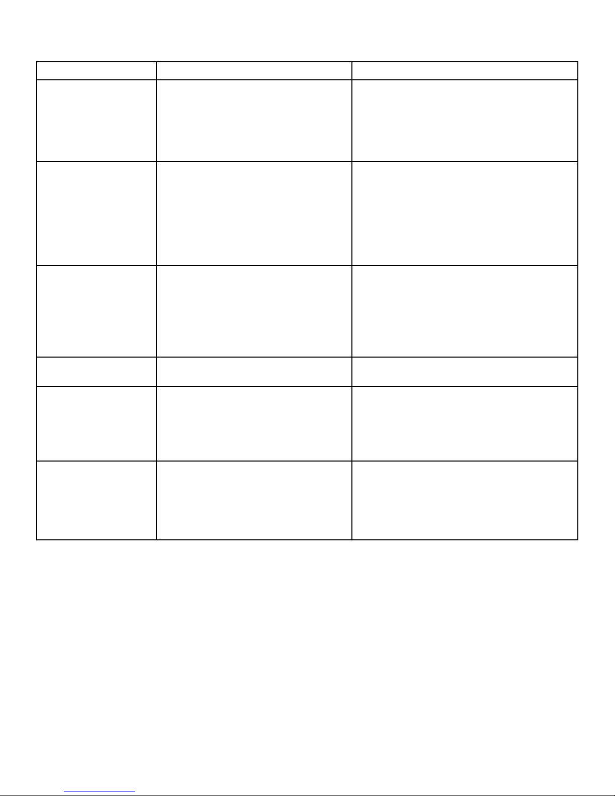
Tabla de solución de problemas
PROBLEMA CAUSA PROBABLE SOLUCIÓN
No arranca la unidad a. No hay energía
b. Disyuntor activado
c. Fusible quemado (en casa)
d. Falla eléctrica
Enfriamiento defi ciente a. Distribución de agua inadecuada (al-
mohadillas no saturadas)
b. Almohadillas sucias o cubiertas de
sedimentos minerales
a. Compruebe que la unidad esté conectada y
que el tomacorriente esté operativo
b. Restablezca el disyuntor
c. Reemplace el fusible en casa
d. Llame a la línea telefónica de ayuda de
Champion
a. Revise la bandeja de distribución de agua y la
manguera por si existen obstrucciones.
- Compruebe que la bomba funciona
correctamente
- Revise que el suministro de agua tenga
el caudal correcto
b. Lave las almohadillas para eliminar polvo y
sedimentos o reemplácelas
Agua en la corriente
de aire
Alta humedad interior a. Insufi ciente fl ujo de aire
Olor en el hogar a. Se produce inicialmente cuando pada
Rápida acumulación mineral en las almohadillas
del medio.
a. El sistema de agua tiene fugas o con-
exiones sueltas
b. Las almohadillas del medio no absor-
ben el agua, que entra directamente al
fl ujo de aire
b. Escape insatisfactorio
se satura primero
b. Crecimiento bacteriano en el depósito
c. La toma de aire está recogiendo el olor
ambiental de los alrededore.
a. Aguas duras a. Instale la bomba de purga para reducir la
a. Revise todas las conexiones de agua, tuberías
y bandeja de distribución para verifi car que no
haya conexiones sueltas, fugas o roturas..
b. Controle el estado de las almohadillas. Limpie
o reemplácelas si fuese necesario.
a. Aumente la velocidad del ventilador
b. Abra más las puertas o ventanas
a. Normal. Se disipará en breve
b. Limpie la unidad de manera regular.
c. Retire la fuente de olor o mueva el enfriador a
otra ventana.
acumulación.
b. Incremente el ciclo de mantenimiento y retire
el sarro con más frecuencia. Controle que los
orifi cios estén sin obstrucción de acumulación
mineral.
26
Page 15

CHAMPION COOLER
5800 MURRAY ST.
LITTLE ROCK, AR
72209
www.championcooler.com
28
72968-R11-16
 Loading...