

Page 1
INSTALLATION AND OPERATING MANUAL
MANUAL DE INSTALACIÓN Y FUNCIONAMIENTO
with
MCP SERIES
MCP44, MCP44E & MCP59
con Funciones de Control Mejoradas
SLIM-LINE
EVAPORATIVE
WINDOW COOLER
LÍNEA DELGADA ENFRIADOR DE VENTANA
Read and Keep this document for future reference.
Access this manual online at www.championcooler.com
Leer y Guardar este documento para consultarlo en el futuro.
Puede acceder a este manual en línea en www.championcooler.com
Enhanced Control Features
Serial number / Número de serie:
72968 -201
Page 2
MasterCool® MCP Series Evaporative Window Cooler
Installation and Operating Manual
Congratulations on your purchase of the MasterCool® MCP Series plastic evaporative cooler. This unit is manufactured with
the intent of offering you years of reliable, ef¿ cient cooling.
NOTE: READ THESE INSTRUCTIONS BEFORE INSTALLING THE COOLER. Follow the installation instructions in
this manual carefully. Varying from them may create safety concerns and will void the warranty.
Safety Instructions
1. Use only with 110V 60 Hz single phase grounded outlet.
2. Ensure cooler is turned OFF and UNPLUGGED before installing, servicing or cleaning the unit.
3 . Do not operate unit with damaged cord or plug, or with any other damaged or missing parts.
4 . Do not run cord under carpeting. Do not cover cord with throw rugs, runners, or similar coverings.
Do not route cord under furniture or appliances. Arrange cord away from traf¿ c area and where it will
not be tripped over.
5. Do not operate cooler with the rear media guard removed.
6. Do not use an extension cord to operate cooler.
7. Do not use an adapter to convert the three pin connector for use in an ungrounded 2 prong outlet.
8. Do not use with a solid state speed control device. Violation of this could cause ¿ re or electrical shock.
9. Do not alter or modify this cooler.
10. Repairs or replacement of electrical components should only be carried out by quali¿ ed electricians.
11. Do not allow children to install, service, or operate the cooler.
12. This fan cannot be used as an exhaust fan in a kitchen, and must be a minimum of 3 feet from open À ame.
Table of Contents
Safety Instructions ........................................................................................................................................................2
Note About Evaporative Coolers .................................................................................................................................... 3
Features of the MasterCool
Installation Procedures .................................................................................................................................................. 4
Cooler Assembly ................................................................................................................................................... 4
Installation in Window ............................................................................................................................................4
Installation in Wall .................................................................................................................................................. 5
Water Connections ......................................................................................................................................................... 6
Water Pump ............................................................................................................................................................. 6
Water Line Connections .......................................................................................................................................... 6
OverÀ ow Drain ........................................................................................................................................................ 7
Water Level ............................................................................................................................................................. 7
Electrical System ............................................................................................................................................................ 7
Operating Instructions .................................................................................................................................................... 8
Optional Installations / Accessories ................................................................................................................................ 8
Optional Purge Pump .............................................................................................................................................. 8
Programming Purge Pump .............................................................................................................................. 9
Optional MasterLink
Optional Plug-in Thermostat Usage ........................................................................................................................9
Servicing Instructions .....................................................................................................................................................10
Annual Maintenance ...............................................................................................................................................10
Winterization ..........................................................................................................................................................12
Troubleshooting ..............................................................................................................................................................12
Cooler Diagram and Parts List ......................................................................................................................................13
Warranty ........................................................................................................................................................................14
Español Manual… ..........................................................................................................................................................15
®
MCP Series Window Cooler ........................................................................................... 3
TM
Thermostat / Remote ...........................................................................................................9
2
Page 3
NOTE: Evaporative coolers
WILL NOT
work in a Closed Room
EXHAUST
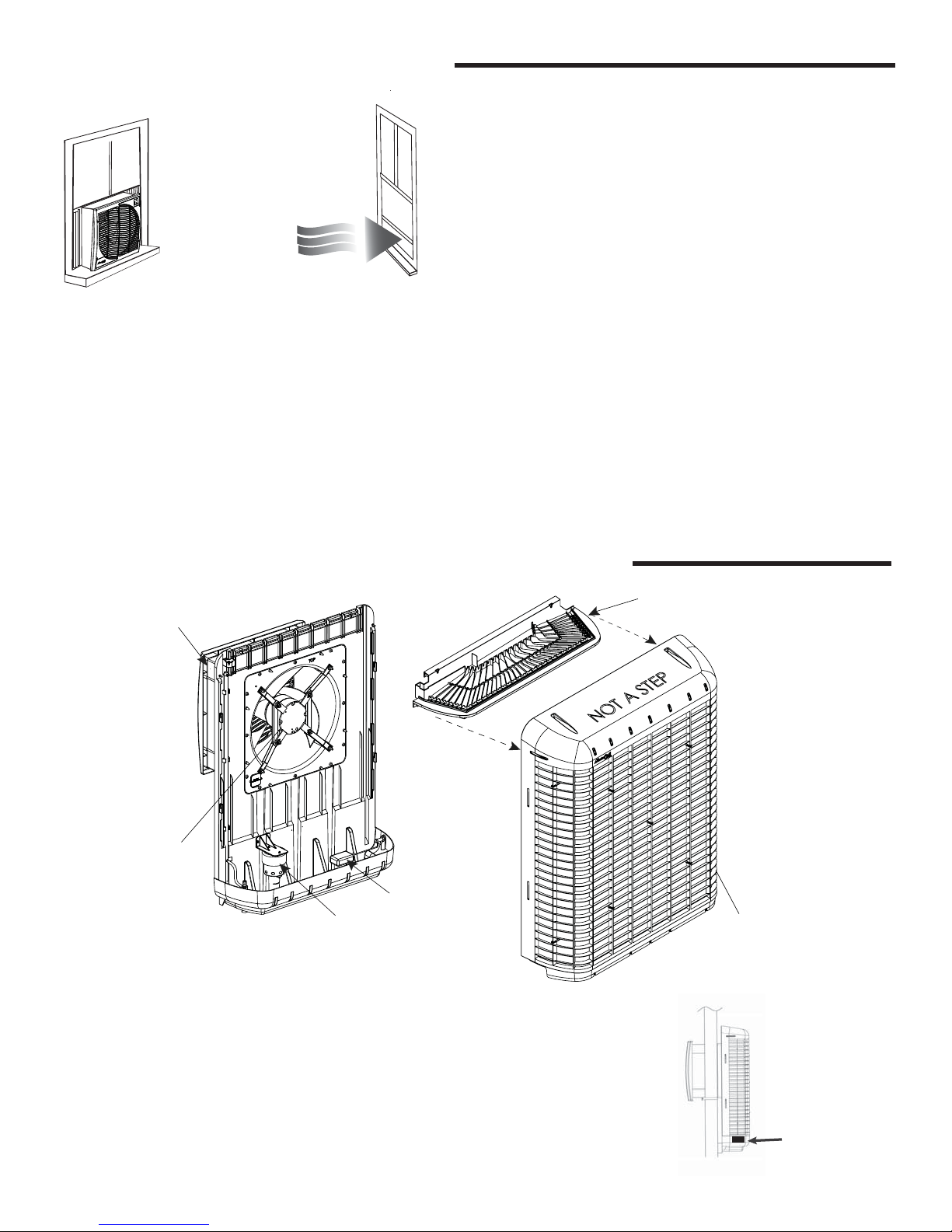
NOTE ABOUT EVAPORATIVE COOLERS
For this cooler to effectively cool
a whole house there must be open
windows or doors in each room
where cooling is desired.
EXHAUST
Door or window should
be open 4 to 6 inches
NOTE: Evaporative coolers
Water bleed or purge:
Evaporative Coolers require a continuous supply of water
to keep the media saturated for maximum cooling. Water
pumped into the cooler must be removed from the unit to
ensure mineral and bacteria build-up do not occur. This can
occur with a gravity-fed steady bleed off stream or a timed
purge system via a pump. A purge pump kit (MCP44-PPK)
is available at www.championcooler.com or at 800.643.8341
to order. See pages 8 and 9 for more details on purge pump
operation.
WILL NOT
work in a Closed Room
Ventilation:
Unlike traditional air conditioners, evaporative coolers require
an open ventilation system, not a closed system. Both a fresh
air source and an exhaust opening are required to provide
correct air À ow. Typically, a partially opened window or door in
each room where cooling is desired will create correct airÀ ow
for optimum effectiveness of an evaporative cooler. Alternately,
attic ventilation ducts such as UP-DUX
p
rovide sufficient air movement without requiring open window
NOTE: For best results, open windows/doors should
not be on the windward side on the house.
CAUTION: Water expelled from the cooler must be
routed away from any areas that could do damage to
foundations or other vulnerable areas.
NOTE: Drawings in this manual are for illustrative
purposes only and may reÀ ect slight differences
depending on design level and con¿ guration.
®
can be installed to
s.
FEATURES OF THE MASTERCOOL® MCP SERIES WINDOW
FAN HOUSING
WITH REMOVABLE
FASCIA
FAN MOTOR
FLOAT
WATER PUMP
COOLER
WATER DISTRIBUTION TRAY
EXTERIOR PORTION
MEDIA GUARD
This cooler’s housing and frame are made of heavy-duty
Ultra-Violet resistant plastic to provide a light weight, easily installable cooler. The unit is constructed in two basic sections
to facilitate quick installation into traditional sash windows or
slider windows.
The high-ef¿ ciency rigid media offers superior cooling over
other types of evaporative coolers.
NOTE: Before installing
unit, take a moment to
record the serial number
and write it on the manual
cover in the space provided.
3
SERIAL NUMBER
ON RIGHT HAND
SIDE OF UNIT.
Page 4
INSTALLATION PROCEDURES
WARNING: Do not connect electrical power to the unit
until the installation is completed.
The MasterCool MCP Series cooler can be installed in a
sash-style or a slider- style window.
Alternatively, this unit is approved for in-wall installations.
In all installations, the following clearances are required:
Width: 22”; Height: 22” ; 4” clearance above the exterior
cabinet is needed for maintenance.
Parts Included:
• Cooler Unit
• Mounting brackets (4)
• Accordion spacers (2) Hardware kit
Tools & Materials Required:
• Drill (power or cordless)
• Assorted drill bits (for drilling pilot holes for mounting
hardware)
• Adjustable Wrench
• Phillips Head Screwdriver
• Silicone or all-weather caulk for sealing in¿ ll panel to
window frame
• Length of ¼” copper or plastic tubing
• Sill-cock valve
• Bubble level
• Spacer material (as required)
OPEN UNIT UP SECURE FAN HOUSING
Cooler Assembly
1. Remove unit from box. Verify that all parts are included.
2. Remove all packing materials.
CALL 1-800-643-8341 IF YOU FIND PARTS
MISSING OR HAVE ANY QUESTIONS
3. With the unit in an upright position, remove 4 screws
holding the back media guard, and separate the front and
back sections. Pull the fan assembly forward (about 6”)
until it is fully engaged with the mating part and secure in
place using the 12 supplied screws.
4. Verify that assembly is secure to prevent vibration between the two sections.
NOTE: Ensure the location selected for installing the
unit is strong enough to support the unit and will accept the mounting hardware. The operating weight of
the cooler is 93 pounds.
NOTE:
installation.
A minimum of two people is required for
3. PULL BACK GUARD
AWAY FROM UNIT
1. REMOVE 4 SCREWS FROM
BACK MEDIA GUARD
2. PUSH UP ON BACK GUARD
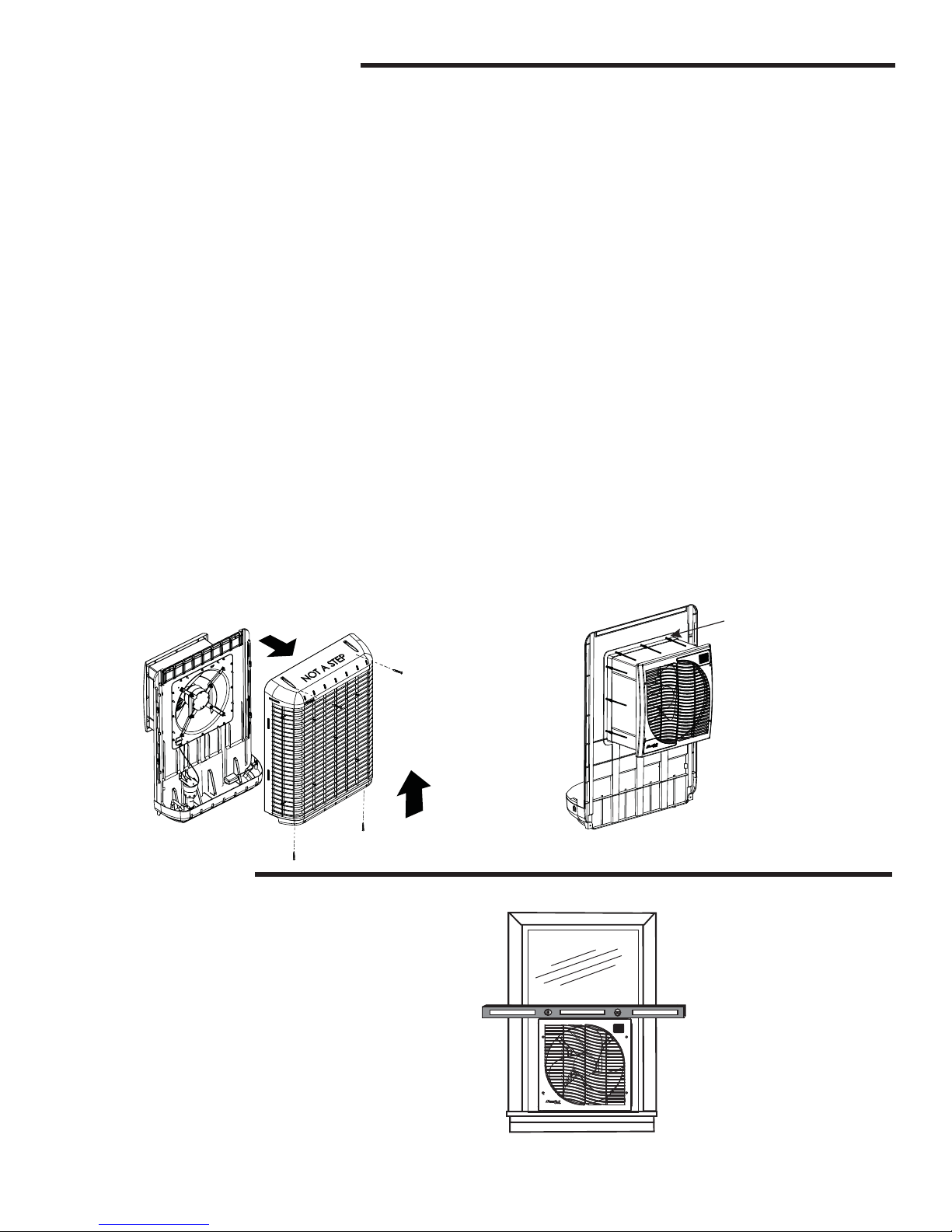
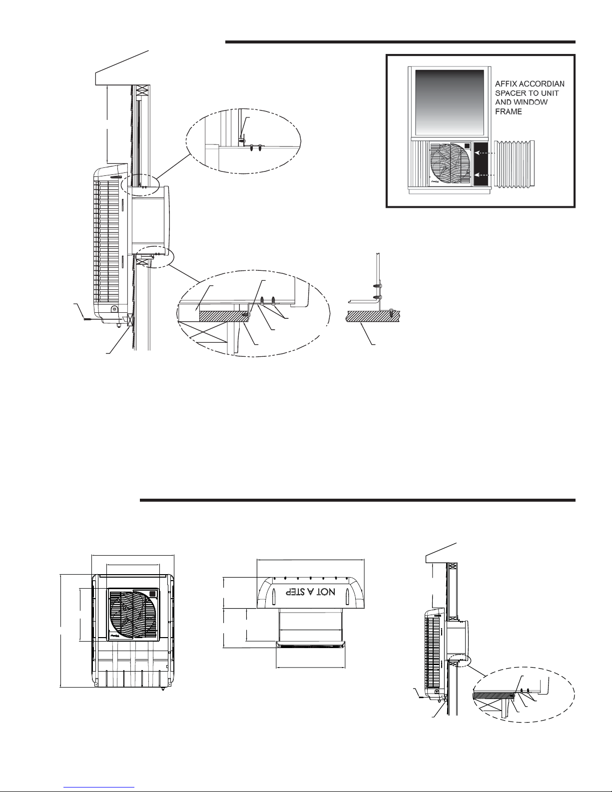
Installation in Window
1. Remove screen (as needed) and make sure window is
opened to its maximum height. From the exterior of the
window, slide the fan assembly section into the window.
Have the person on the interior adjust the exact placement of the unit for aesthetics and correct lengths of the
two accordion spacers (included).
Note: After identifying the position for installation,
place a bubble level on top of the unit and make adjustments to ensure the unit will be level when installation is complete. It is recommended to verify unit is
level at various points during installation.
EXTEND HOUSING AND
ATTACH IT TO
COOLER BODY FRONT
WITH 12 SCREWS
3. From the interior, locate
the two tracks on the
bottom of the fan assembly. Drill pilot holes as
necessary and install the
two window sill brackets
as shown in illustration on
following page.
2. Closing the window may help hold the unit in place during
the following steps – Push the unit into the window until
the bottom is À ush with the outside wall or spacer (not
supplied) as shown in the illustration.
4
Page 5
Installation in Window (continued)
4" MINIMUM
SCREWS
SPACER TO ENSURE
FLUSH/SQUARE
INSTALLATION
(NOT SUPPLIED)
2 PLACES - MINIMUM 14" APART
WINDOW
WINDOW
SCREW
WINDOW SILL BRACKET
WINDOW SILL
4. Secure the top of the fan housing to the window frame
with two additional brackets and screws.
5. From the outside, secure the unit to the exterior wall (or
spacer) with two screws at the base of the back cover
(as shown in illustration.) Complete the installation of
the exterior portion with two screws at the top of the back
media guard.
SCREWS
WINDOW SILL
OPTIONAL MOUNTING
6.
With the unit now installed in the window, attach one ac
accordion spacer to each side of the fan assembly using
the adhesive backed edges. Short screws(not included)
can be used for a more secure installation. (Make sure
screws do not interfere with fan blade.)
7. Once accordion spacers are installed, seal any gaps
around the units with silicone or all weather caulk (not
supplied).
Installation in Wall
This cooler is approved for in-wall installation. Contact a licensed contractor to have the cooler installed in an outside wall.
5
"
33
/
8
215/
8
"
215/
8
"
1
"
/
8
46
FRONT VIEW
12
9 3/
33 5/
8
"
4
"
5
3
/
8
"
10
/
16
"
19 13/
16
"
21 5/
8
"
TOP VIEW
SPACER TO ENSURE
FLUSH/SQUARE
(NOT SUPPLIED)
4" MINIMUM
SCREWS
INSTALLATION
SCREW
SCREWS
SILL BRACKET
SILL PLATE
5
Page 6
T
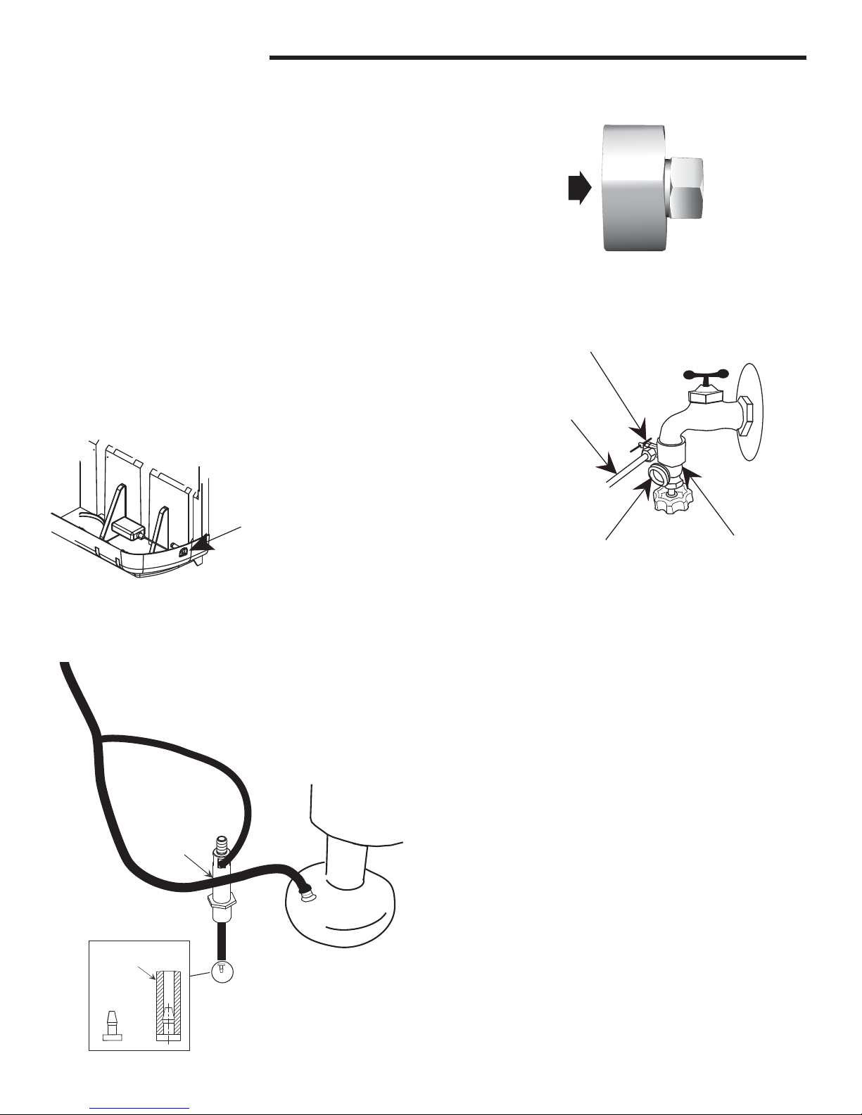
WATER CONNECTIONS
Steady water supply is required for operation of the cooler. If taking
water from an external faucet, there are two options for attaching
water to the cooler.
Option 1:
Using a standard water hose to supply water:
1. Remove the nut and ferrule that secures the À oat ¿ tting in the
unit at the attach point.
2. Take the brass ¿ tting enclosed in the parts bag and attach
one end to the À oat valve and the other end to the water hose.
Option 2:
Install a sill-cock onto faucet to facilitate a dedicated water line to
the cooler.
SCREWS
DIRECTLY
ONTO END OF
WATER HOSE
SCREWS DIRECTLY
ONTO FLOAT VALVE
1. Install a standard sill-cock (locally available) with water
valve onto the faucet and connect the water supply to the
cooler.
2. Install plastic or copper line to sill-cock and connect it to the
À oat valve.
FLOAT VALVE
WATER LINE
ATTACH POIN
Water Pump
A self-contained water pump continuously circulates water through the
water distribution system and over the media.
The pump and water lines are shipped disconnected.
MAIN
WATER
LINE
JUNCTION
PUMP
(STRAINER NETTING
NOT SHOWN
OVERFLOW
DRAIN
FITTING
REMOVE NIPPLE FROM
TUBE BEFORE FEEDING
IT INTO DRAIN OVERFLOW.
REINSTALL NIPPLE INTO
OVERFLOW LINE
(AFTER
INSERTING
LINE THROUGH
OVERFLOW
FITTING)
PUMP
INLET
FOR CLARITY)
SHUT OFF VALVE
PLASTIC OR
COPPER LINE
TO COOLER
STD. HOSE CONNECTION
SILL-COCK
Water Line Connections
1. Locate the black water line snapped into plastic
keepers inside the unit.
2. Attach the bottom end of the main water line to the
pump inlet.
3. Remove the nipple inserted into the end of the
overÀ ow line. Push overÀ ow hose into one of the
slots in the sides of the overÀ ow drain ¿ tting.
4. Reinsert the nipple into the overÀ ow line.
5. Attach the top of the hose to the water distribution
tray.
6. Ensure there are no kinks in the water lines after
completion.
NIPPLE
6
Page 7
WATER CONNECTIONS (CONT’D)
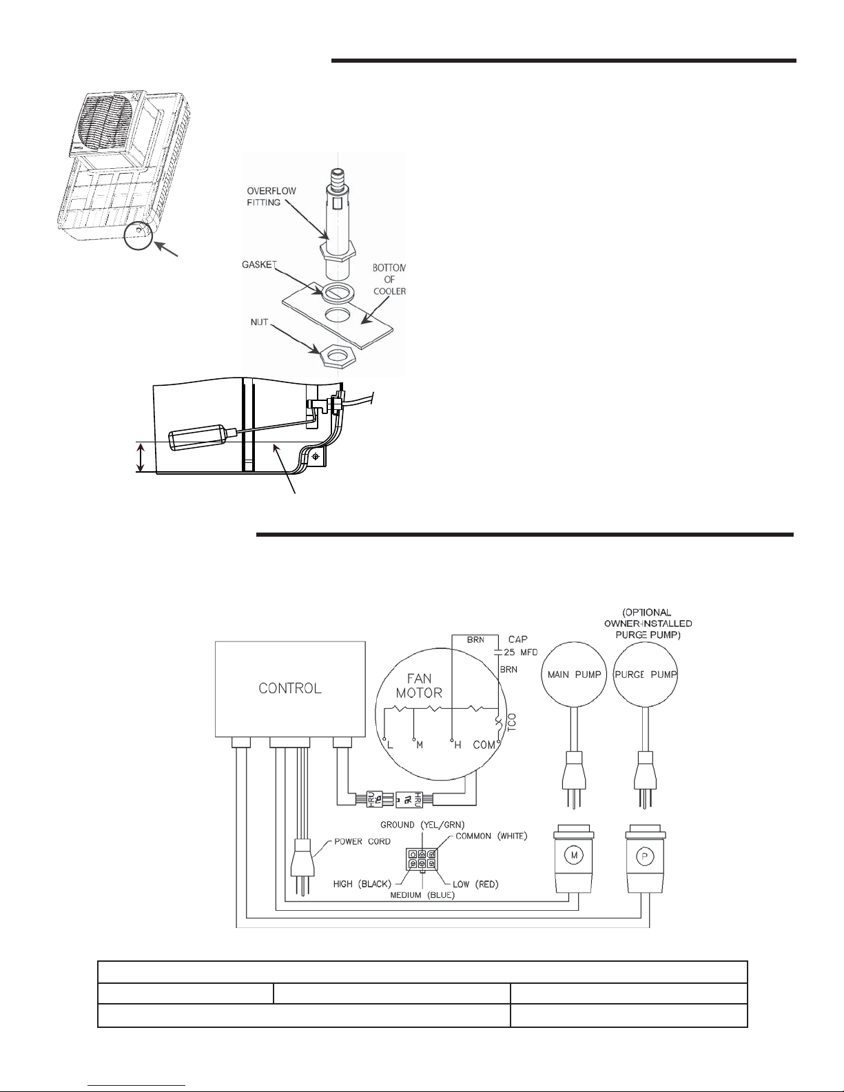
OverÀ ow Drain
1. Slide the rubber washer over the overÀ ow ¿ tting and push
through the hole in the bottom of the cooler from the top
side.
2. Secure the drain from beneath the pan with the Lock Nut.
3. Make sure the rubber washer does not twist while tightening, which could cause it to leak. DO NOT OVER TIGHTEN.
LOCATION
OF DRAIN
4. If leakage occurs after reservoir is full, re-tighten the overÀ ow ¿ tting until leaking stops. A small amount of silicone
caulk may be used if necessary.
tach a drain hose to the bottom of the ¿ tting if neces-
5. At
sary.
Water Level
Two inches of water should be maintained in the bottom of
the cooler to ensure suf¿ cient water for correct operation of
the cooler.
2˝
WATER LEVEL
The À oat is factory-installed to maintain a 2 inch level of
water, but may require adjustment if shipping or installation
has caused the setting to shift.
ELECTRICAL SYSTEM
The electrical system does not require general maintenance. The following wiring diagram is supplied for reference only.
ELECTRICAL SPECIFICATIONS OF MCP SERIES COOLERS
MCP Series Fan Motor 120 V, 2.8 amps Main Pump 120 V; 0.9 amps
If optional Purge Pump is installed Additional 0.9 amps
7
Page 8
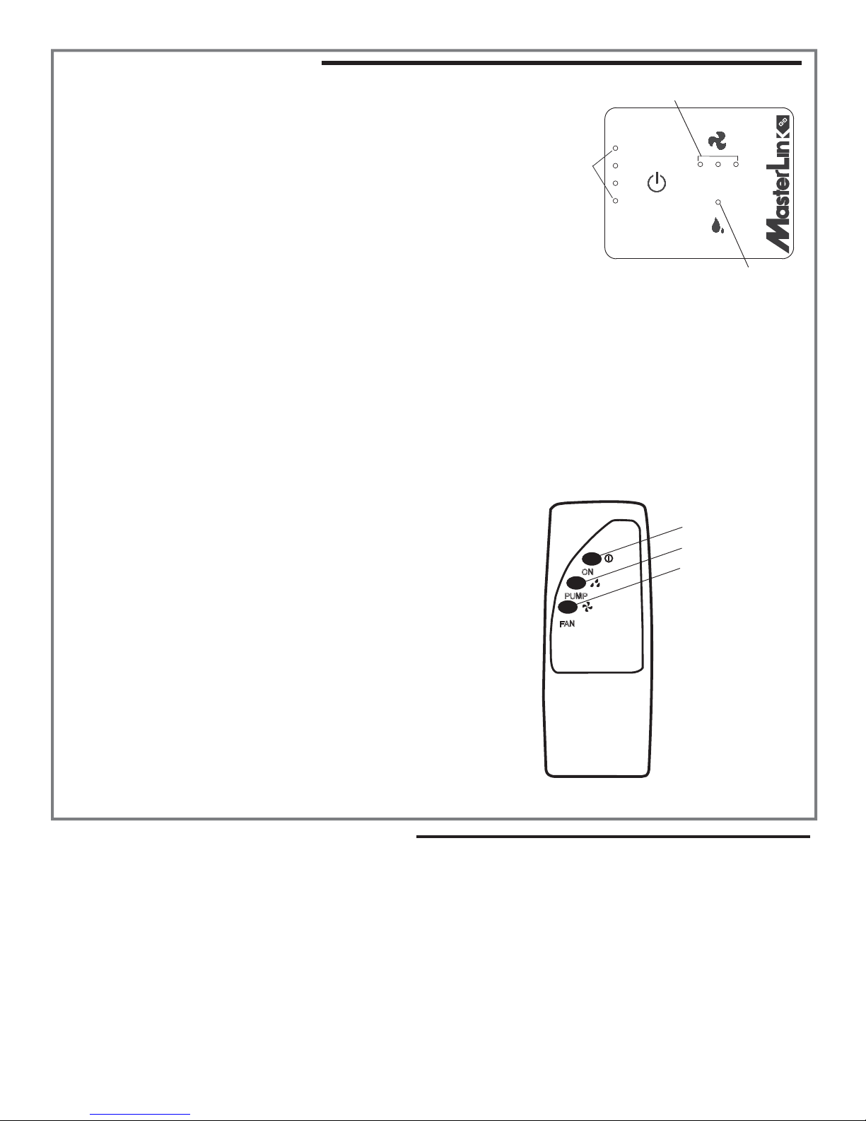
OPERATING INSTRUCTIONS
The MCP Series of Coolers has an electronic touch control panel in the
upper right hand corner.
Before turning unit on, ensure unit is plugged in, water supply to pump is
on, and there is correct ventilation, as shown on page 3 of this manual.
Note:
The MCP series coolers is controlled by the 3 buttons on
the front panel of the cooler or with the remote control
.
Purge Pump
Programming
Indicator lights
Fan Speed Indicator Lights
FAN
HI
M
ED LO
POWER
On/Off
This button initiates power to the unit. When ¿ rst plugged, pressing ON/
OFF and will start the unit in the default setting (pump ON and Fan on
HIGH). After its initial use, the last operating settings (for fan and pump)
will be reinstated when the unit is turned on again.
Pressing this button when the unit is already running will turn both fan and pump off.
After A Power Failure: Once power is restored, the unit will restart in the same settings as before power was lost.
PUMP
Pump Power Indicator
Pump
This button toggles the pump on and off. When the LED is lit, the pump is running.
The pump must be on while operating the fan for the unit to operate as an evaporative cooler, though the unit can be
used in fan mode without the pump, if desired.
Note: For best results turn on the pump for a few minutes to wet the pads
before operating the fan.
Fan
Pressing the fan button cycles the unit from HIGH, to MEDIUM to LOW
speeds and then OFF.
Please Note: There is a two second delay from the pressing of the button
for the fan to engage or change speeds. This applies to the front control
panel and the remote control.
ON
PUMP
FAN
Unit Power ON/OFF
Pump ON/OFF
Fan Speed (1-3)
Remote Control
The remote control supplied with this cooler allows you to turn the unit
on or off, control fan speed and initiate the pump. The buttons operate
i
n the same manner as those on the front control panel.
The remote control’s range is approximately 20 feet within sight
of the cooler. It uses two AA alkaline batteries (included). A wall
mountable holder is also supplied with the remote.
OPTIONAL INSTALLATIONS/ ACCESSORIES
Optional Purge Pump
In addition to the standard water pump to recirculate water
from the reservoir, a purge pump can be installed to evacuate
the contents of the reservoir on a scheduled basis.
reduce bacterial growth and mineral buildup on the media, extending its life.
It also maintains fresher air in the home.
The use of the purge pump saves water and is actually more
economical, than continual bleed. The purge pump kit (P/N
MCP44-PPK) for this unit may be purchased locally or online
at www.championcooler, or by phone at 1.800.643.8341.
This helps
Purge Pump Discharge: The water ejected at the time of
purging will be expelled at a high rate of speed, and must
be routed away from the foundation of the home or other
areas where rushing water could do damage.
1. Attach a standard water hose to the overÀ ow drain to
direct the water away from the house.
NOTE: This water is not potable, but can be used for watering vegetable or À ower gardens.
8
Page 9
P
OPTIONAL INSTALLATIONS / ACCESSORIES (CON’T)
PROGRAMMING PURGE PUMP
NOTE: When in Purge Set Up Mode, you will not affect the fan speed or main water pump operation.
Once a purge pump has been installed and plugged
into the cooler, the purging cycle can be programmed
from the control panel:
The default setting for the purge pump is 1 minute of
purge every 24 hours. This setting can be changed to
increase interval and duration of purges as needed.
order to enter the programming
In
mode of the control panel hold
down the PUMP touch point for
¿ ve (5) seconds.
At this point the Purge Interval
PRESS AND
HOLD 5
SECONDS
PUM
FAN
can be set. Four lights on the
HI
M
left side illuminate.
purge every 24 hours.
one
This indicates
POWER
ED LO
PUMP
To change the number of hours between purges,
press PUMP again until the desired schedule is selected. The options for purge interval are 24,12, 8 and 6
hours. The lights decrease by one each time the Pump
button is pressed. Note the legend of intervals listed
below.
NOTE: Depending on the amount of minerals in
the local water, it may be advantageous to increase the purges to extend the life of the media
and the unit.
After the number of hours in the Purge Interval has
been set, you may select the duration of the purge.
Options are from 1 to 4 minutes that the water will be
expelled.
Press the FAN touch point
to enter the Purge Duration
setting feature.
PRESS TO
SET PURGE
DURATION
FAN
The four lights on the left side
POWER
FAN
HI
M
ED LO
PUMP
,
will begin blinking indicating 4
minutes of purging. Press the
PUMP touch point to change
the setting from 4 to 3 minutes,
then 2 or 1 minute duration.
To save and exit the Duration portion of the programming
press and hold the FAN touch point for 5 seconds.
NOTE: If no touch-point is pressed within 10 seconds, the program will automatically exit the set up
mode and retain previous settings.
4 LIGHTS = EVERY 24 HOURS
3 LIGHTS = EVERY 12 HOURS
2 LIGHTS = EVERY 8 HOURS
1 LIGHT = EVERY 6 HOURS
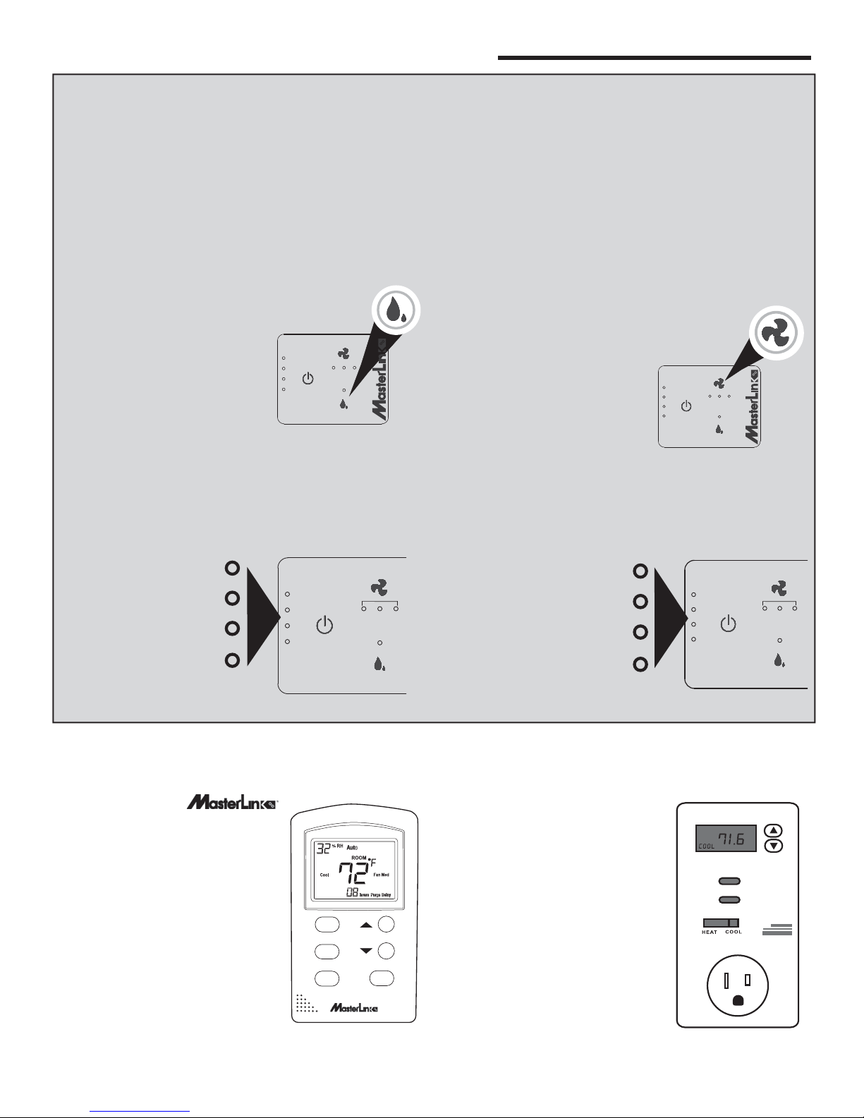
Optional MasterLink
TM
Thermostat
(Available in 2017)
MasterCool® MCP Series coolers
manufactured with the
logo on the control panel will be
compatible with the MasterLink
Thermostat, sold separately. The
thermostat will have a smart phone
app that allows wireless control over
the cooler. This thermostat controls
standard and advanced features,
such as purge pump control and
timer function.
Refer to the MasterLink
TM
owner’s manual for instructions on
how to control and program the MCP
Series coolers using this item.
TM
Thermostat
POWER
Fan
Pump
Mode
HI
FAN
M
ED LO
PUMP
Timer
4 LIGHTS BLINKING = 4 MINUTES
3 LIGHTS BLINKING = 3 MINUTES
2 LIGHTS BLINKING = 2 MINUTES
1 LIGHT BLINKING = 1 MINUTE
Optional Plug-In Thermostat Usage
The MCP Series also can be controlled by a plug-in programmable
thermostat, such as the LUX brand
WIN 100. These thermostats
are locally available, and enable
precise timing and temperature
control
that plugs into a 110 volt outlet. To
use such a device with the MCP
series cooler, follow the instructions
for the speci¿ c thermostat and plug
the cooler into the outlet on the
thermostat.
NOTE: Illustration is for reference
only, models and features vary by
model and manufacturer.
via an electronic thermostat
POWER
HI
FAN
M
ED LO
PUMP
9
Page 10

SERVICING INSTRUCTIONS
Maintenance on evaporative coolers is minimal,
but very important to the proper operation and
effectiveness of your cooler. Periodic inspection
of the cooler’s interior will reduce the potential for
substandard cooling due to insuf¿ cient or uneven
water distribution.
NOTE: For general maintenance purposes, the unit
may be rapidly drained of water by removing the
overÀ ow ¿ tting from the bottom of the unit. This is not
adequate draining for winterization (see procedures
under Winterization section.)
1. Remove the back media guard (as shown below).
2. Inspect pads in place. Remove media pads from back
guard by unscrewing the media peg clips. Be careful not
to chip or damage the media while removing. Visually
inspect both sides of media pads. Look for blockage,
mineral build-up or mildew growth, breakage or other
anomalies.
3. Wash pads with a garden hose. Do not use a pressure
washer.
4. Check water distributor for blockage or excessive buildup
of dust.
Annual Maintenance
(May be Needed More Often in Areas with Hard Water)
Cleaning
WARNING: Disconnect from electrical power and turn
unit off during all maintenance. Turn water supply off
before removing back for cleaning or maintenance.
CAUTION: In order to maintain UV resistance, do not
use abrasive cleaners on the exterior of the cooler
body.
d
. PULL BACK GUARD
c
. DISCONNECT WATER
SUPPLY HOSE
NOTE: Whenever
the back is removed
from the cooler,
always verify the
water supply tube is
reconnected to the
water distribution
tray before operating
the cooler.
AWAY FROM UNIT
OPTIONAL
OWNER-INSTALLED
PURGE PUMP
5. Set media in a safe place until all maintenance is complet
e.
6. Wash out reservoir thoroughly using a soft bristle brush.
Use plenty of water to remove algae growth. Clean areas
around pump, strainer and À oat to ensure no algae
growth remains.
CAUTION: Do not use harsh chemicals (like chlorine
bleach) to clean the interior portions of the cooler.
7. Rinse thoroughly after using any cleaning solutions on
the interior or exterior of the unit.
a
. REMOVE 4 SCREWS FROM
BACK MEDIA GUARD
b
. PUSH UP ON BACK GUARD
LOCATE MEDIA PEGS AND REMOVE.
USING PLIERS,
PULL PLUGS
OUT FROM THE
EXTERIOR.
10
OR PULL CLIPS
OFF PEGS FROM
THE INTERIOR.
Page 11

Annual Maintenance (Con’t)
Water System Pump:
1. The water pump is a self-contained unit that should require no maintenance other than ensuring that no debris
or corrosion interferes with free movement of the parts.
2. Ensure hose connection to pump is in good condition.
Water Float:
3. The À oat level is factory set for optimum performance,
however moderate adjustments can be made by bending
the À oat arm for a different water level.
4. The maximum recommen
ded water level is approximately
two inches (the height of the overÀ ow ori¿ ce.)
Water Distributor
5. Inspect the water distribution section to ensure all ori¿ ces
are clear.
6. Verify the hose connections are in good order and no
kinks or tears are present.
Water Drain OverÀ ow
7. Unscrew the drain overÀ ow pipe and check the condition
of the gasket at the bottom of the ¿ xture. When reinstall-
ing, ensure the standpipe ¿ xture is secure and there is no
leakage after the reservoir is ¿ lled.
WATER
FLOAT
WATER
SYSTEM
PUMP
WATER
DISTRIBUTOR
NOTE: If during usage of the cooler you start noticing low saturation of pads and insuf¿ cient cooling, or
leakage from the cooler, check the gasket at the base
of the standpipe. This is the most likely cause of leakage on this unit.
Optional Water Purge Pump (if installed)
8. If a purge pump has been installed on the MCP Series,
check that the purge pump and strainer are corrosion-free with freely moving parts.
OPTIONAL
PURGE PUMP
(OWNER INSTALLED)
Media Pad Replacement
9. When the media pads have become encased with mineral buildup, broken or damaged, replace them with Genuine Munters GreenGuard Celdek
model MCP44-PAD. You may purchase them on-line at
www.championcooler.com or by calling 1.800. 643.8341.
®
replacement pads,
11
Page 12

Winterization
The MCP Series cooler is durable enough to be left installed
during the winter, though a few precautions must be taken to
ensure no water freezes in the unit or lines.
If the temperatures in your area drop well below freezing it
may be wise to remove the water supply line from the
outside faucet.
Draining
1. Turn the water supply to the cooler off.
2. Turn off and unplug cooler. Remove 4 screws securing
the back media guard and access interior of unit.
3. Soak up any remaining water and ensure all water is
drained from both the water pump and purge pump
(if installed).
4. Disconnect and drain the water hoses and water
distributor.
When Optional owner-installed purge pump is installed:
1. Turn off the water supply to the cooler.
2. Turn off and unplug cooler.
3. Remove four screws securing the back media guard and
access the interior of the unit.
4. Soak up any remaining water and ensure all water is
drained from both the water pump and the purge pump.
5. Disconnect and drain the water hoses and water distributor
6. Replace the media guard.
Covering
1. An optional weatherproof exterior ¿ tted cover, model
MCP44-EC is available for purchase on line at www.
championcooler.com, at retail outlets or by calling
1.800.643.8341.
a. Use the elastic corners and straps to secure the
cover onto the back of the unit.
2. An optional interior grille cover, model MCP44-IC
(Included with MCP44E) to keep air from entering the
home through the window is available at www.championcooler.com, a retail outlet or by calling 1.800.643.8341.
a. Use the snap on clips molded into the cover to
secure the cover to the grille.
.
TROUBLE SHOOTING CHART
PROBLEM PROBABLE CAUSE SOLUTION
Unit will not start a. No Power
b. Tripped Circuit Breaker
c. Blown home fuse
d. Electrical fault
Insuf¿ cient Cooling a. Inadequate water distribution (pads not
saturated)
b. Pads dirty or covered with mineral
deposits
Water in air stream a. Water system has leaks or loose
connections
b. Water is not being absorbed by media
pads, and entering straight into airÀ ow
High indoor humidity a. Insuf¿ cient air À ow
b. Unsatisfactory exhaust
Odor in home a. Occurs initially when pads are ¿ rst
saturated
b. Bacterial growth in reservoir
c. Air intake is picking up ambient odor
from surroundings
Rapid mineral buildup on
media pads
a. Hard water a. Install purge pump to reduce build-up.
12
a. Verify unit plugged in; and outlet is functional
b. Reset Circuit Breaker
c. Replace home fuse
d. Call Champion Help line: 1.800.643.8341
a. Check water distribution tray and hose for
blockages.
- Verify pump operating correctly
- Check water supply for correct À ow
b. Wash dirt & deposits off pads or replace pads
a. Check all water connections, tubing, distribu-
tion tray for loose ¿ ttings, leakage or tears.
b. Check condition of pads. Clean or replace as
necessary.
a. Increase fan speed
b. Open doors or windows more
a. Normal. Will dissipate shortly.
b. Clean unit regularly
c. Remove source of odor or move cooler to
another window
b. Increase maintenance cycle and wash off
scale more often. Check ori¿ ces are clear of
mineral buildup.
Page 13

COOLER DIAGRAM AND PARTS LIST
19
(2 ea.)
17
20
16
12
18
(4 ea.)
15
13
14
2
4
5
1
6
3
7
OPTIONAL ACCESSORIES
22
PURGE PUMP KIT
24
23
11
8
Kit includes full set
of media, pegs
and keepers
PAD REPLACEMENT KIT
10
(OPTIONAL
OWNER INSTALLED
PURGE PUMP)
MCP44 (1 pump)
9
ON
PUMP
FAN
CHAMPION / ESSICK AIR
EXTERIOR COVER
21
INTERIOR COVER
(INCLUDED ON MCP44E)
25
AVAILABLE IN 2017
26
REMOTE
THERMOSTAT
ITEM DESCRIPTION PART NUMBER
1 Cooler Back/Media Guard 72243
2 Set of 4 screws for attaching back guard 72303
Back Media Pad; 2” X 24” X 35.5” Munters GreenGuard certi¿ ed CelDek
3
72244
4 Side Media Pad; 2” X 5.88” X 35.5” CelDek (2 ea.) 72245
5 Water distributor tray 72249
6 Tray cap 72250
7 Media Peg Clip; window cooler; PP (9 ea.) 72246
8 Media Peg; window cooler; PP (9 ea.) 72247
9 Pump assy. – Main water system 72402
10 MCP Series Water Distribution Hose assy. 72256
11 Float valve 72290
12 Cooler body front 72242
13 Receptacle cover 72407
14 Fan motor 72428
15 Fan Blade 72253
16 Fan Housing 72251
17 Grille 72257
18 Grille screw caps 72260
19 Control module
72
20 Vinyl accordion window panel (2 ea.) 72284
21 Remote control (IR- included with unit)
72302
OPTIONAL ACCESSORIES - Available for Purchase · Call 1.800.643.8341
22 Purge Pump Kit MCP44-PPK
23 Pad Replacement Kit
24 Exterior Cover
25 Interior Grille Cover
26 Remote Thermostat - AVAILABLE IN 2017
MCP44-PAD
MCP-EC
MCP-IC
ML-THERM
13
Page 14

MASTERCOOL MCP SERIES COOLER
ONE YEAR LIMITED WARRANTY
SALES RECEIPT REQUIRED AS PROOF OF PURCHASE FOR ALL WARRANTY CLAIMS.
This warranty is extended only to the original purchaser of this evaporaƟ ve cooler when the unit is installed and used under
normal condiƟ ons against defects in workmanship and materials as follows:
• One (1) year from date of sale on the unit, and
• Five (5) years on the evaporaƟ ve media, which is considered a disposable component and should be replaced
periodically, and
• Two (2) years on motor.
The manufacturer will replace the defecƟ ve part/product, at its discreƟ on, with return freight paid by the manufacturer. It is
agreed that such replacement is the exclusive remedy available from the manufacturer and that TO THE MAXIMUM EXTENT
PERMITTED BY LAW, THE MANUFACTURER IS NOT RESPONSIBLE FOR DAMAGES OF ANY KIND, INCLUDING INCIDENTAL AND
CONSEQUENTIAL DAMAGE OR LOSS OF PROFITS OR REVENUES.
Some states do not allow limitaƟ ons on how long an implied warranty lasts, so the above limitaƟ ons may not apply to you.
Exclusions from this warranty
We are not responsible for any incidental or consequenƟ al damage from any malfuncƟ on, accident, misuse, alteraƟ ons,
unauthorized repairs, abuse, including failure to perform reasonable maintenance, normal wear and tear, nor where the
connected voltage is more than 5% above the nameplate voltage.
AlteraƟ ons include the subsƟ tuƟ on of name brand components including, but not limited to media pads.
We are not responsible for any damage from the use of water soŌ eners or treatments, chemicals or descaling materials.
We are not responsible for the cost of service calls to diagnose the cause of trouble, or labor charge to repair and/or replace
parts.
No employee, agent, dealer or other person is authorized to give any warranƟ es or condiƟ ons on behalf of the manufacturer.
The customer shall be responsible for all labor costs incurred.
Some states do not allow the exclusion or limitaƟ on of incidental or consequenƟ al damages, so the above limitaƟ ons or
exclusions may not apply to you.
How to obtain service under this warranty
Within the limitaƟ ons of this warranty, purchaser with inoperaƟ ve units should contact the dealer where you purchased the
cooler. If for any reason you are not saƟ sĮ ed with the response from the dealer, contact Customer Service at 800-643-8341
for instrucƟ ons on how to obtain service within warranty as listed above.
This warranty gives the customer speciĮ c legal rights, and you may also have other rights which vary from province to
province, or state to state.
Register your product at www.championcooler.com.
MasterCool® by Champion Cooler
5800 Murray St.
Little Rock, AR 72209
800.643.8341
www.championcooler.com
14
Page 15

Enfriador Evaporativo de Ventana del MasterCool® MCP Serie
Instrucciones de uso e instalación
Felicitaciones por haber comprado el enfriador evaporativo plástico MasterCool® MCP Serie.
Esta unidad se fabricó con el propósito de brindarle un enfriamiento con¿ able y e¿ ciente durante años.
NOTA: LEA ESTAS INSTRUCCIONES ANTES DE INSTALAR EL ENFRIADOR. Siga atentamente las instrucciones de instalación de este manual. En caso contrario, podrían ocasionarse problemas relacionados con la seguridad y invalidar la garantía.
Instrucciones de seguridad
1. Use la unidad únicamente con un tomacorriente monofásico con conexión a tierra de 110 V y 60 Hz.
2. Asegúrese de que el enfriador esté APAGADO y DESENCHUFADO antes de realizar la instalación, el mantenimiento
o la limpieza de la unidad.
3. No opere la unidad con un cable o enchufe dañado ni con otras piezas dañadas o faltantes.
4. No haga funcionar el cable debajo de la alfombra. No cubra el cable con alfombras, alfombrillas o revestimientos similares. No cable de ruta debajo de los muebles o electrodomésticos. Coloque el cable lejos del área de trá¿ co y donde
no se pueda tropezar.
5. No opere el enfriador con la protección posterior del medio extraída.
6. No utilice un cable prolongador para operar el enfriador.
7. No use un adaptador para convertir el conector de tres clavijas para utilizar en un tomacorriente sin conexión a tierra
de 2 espigas.
8. NO lo use con un dispositivo de control de velocidad de estado sólido. Si lo hace, podría ocasionar un incendio o
descarga eléctrica.
9. No altere ni modi¿ que este enfriador.
10. Los componentes eléctricos deben ser reparados o reemplazados únicamente por electricistas cali¿ cados.
11. No permita que niños operen o realicen la instalación o el mantenimiento del enfriador.
12. Este ventilador no se puede utilizar como un extractor de aire en la cocina, y debe tener un mínimo de 3 pies de la
llama abierta.
Índice
Instrucciones de seguridad .................................................................................................................................................... 15
Nota acerca de los enfriadores evaporativo: ..........................................................................................................................16
Funciones del enfriador de ventana MasterCool
Procedimientos de instalación ................................................................................................................................................17
Montaje del enfriador .............................................................................................................................................................17
Instalación en ventana ...........................................................................................................................................................18
Instalación empotrada ............................................................................................................................................................18
Conexión de agua ..................................................................................................................................................................19
Bomba de agua ...................................................................................................................................................................19
Conexion de las tuberías de agua ....................................................................................................................................19
Desborde de Drenaje .........................................................................................................................................................20
Nivel de agua ......................................................................................................................................................................20
Sistema eléctrico ....................................................................................................................................................................20
Instrucciones de uso ...............................................................................................................................................................21
Accesorios/ instalaciones opcionales .....................................................................................................................................21
Opcional Bomba de purga ......................................................................................................................................................21
Programación de la bomba de purga .....................................................................................................................................22
Termostato opcional/remoto MasterLink .................................................................................................................................22
Uso del opcional de termostato plug-in ..................................................................................................................................22
Servicio usuario Instrucciones ................................................................................................................................................23
Mantenimiento anual .............................................................................................................................................................24
Acondicionamiento para el invierno ........................................................................................................................................25
Tabla de solución de problemas .............................................................................................................................................26
Diagrama del enfriador y lista de piezas ................................................................................................................................27
Garantia ............................................................................................................................................................................... 28
®
..................................................................................................................16
15
Page 16

NOTA ACERCA DE LOS ENFRIADORES EVAPORATIVO
Ó
Para enfridaor trabajar mejor, tiene que
haber una vnetana o puerta abierta
en cada habitacion donde
el enfriamiento
es deseado.
ESCAPE
Ventana o puerta
abierta 4-6 pulgades
NOTA: Elos enfriadores evaporativo NO funcionan
en habiaciones cerradas
Purga de agua:
Los enfriadores evaporativo requieren un suministro de agua
continuo para mantener saturado el medio y lograr un máximo
enfriamiento. Debe retirarse de la unidad el agua bombeada
dentro del enfriador para evitar la acumulación de minerales
y bacterias. Esto puede suceder por acción gravitatoria de
un À ujo de descarga constante o por un sistema de purga
programado a través de una bomba. . La bomba de purga
(MCP44-PPK) está disponible en www.championcooler.com
o llamando al 1.800.643.8341.Consulte las páginas 21 y 22
para obtener más detalles acerca del funcionamiento de la
bomba de purga.
Ventilación:
A diferencia de los acondicionadores de aire, los enfriadores
evaporativo necesitan un sistema de ventilación abierto y no
cerrado.
Se requieren tanto una fuente de aire fresco como una apertura de escape para generar una correcta circulación de aire.
En general, una ventana o puerta parcialmente abierta en
cada habitación donde se desea enfriamiento creará el À ujo
de aire adecuado para una efectividad óptima de un enfriador
por evaporación. De manera alternativa, los conductos de
ventilación del ático como UP-DUX® se pueden instalar para
proporcionar un movimiento de aire su¿ ciente sin necesidad
de ventanas abiertas.
NOTA: Para mejores resultados, las ventanas/puertas
abiertas no deben estar en la parte de la casa enfrentada al viento.
ADVERTENCIA: El agua expulsada del enfriador debe
dirigirse lejos de cualquier área que pudiera afectar
los cimientos u otras zonas vulnerables.
NOTA: Los dibujos de este manual son para ¿ nes
ilustrativos y pueden reÀ ejar pequeñas diferencias en
función de las diferencias de diseño y con¿ guración.
FUNCIONES DEL ENFRIADOR DE VENTANA MASTERCOOL® MCP SERIE
CARCASA DEL VENTILADOR
C/ FRENTE DESMONTABLE
MOTOR DEL
VENTILADOR
FLOTADOR
OPCIONAL
BOMBA DE AGUA
BOMBA DE PURGA
La carcasa y la estructura de este enfriador están realizados
en un plástico reforzado y resistente a los rayos UV, lo que da
como resultado un enfriador liviano y de fácil instalación. La
unidad está construida en dos secciones básicas para posibilitar una rápida instalación dentro de ventanas a guillotina o
corredizas.
El medio rígido de altísima e¿ ciencia brinda un enfriamiento
superior, comparado con otros enfriadores a evaporación.
BANDEJA DE DISTRIBUCI
DE AGUA
NOTA: Antes de insta-
lar la unidad, tómese
un momento para
anotar el número de
serie y escribirlo en la
cubierta del manual en
el espacio provisto.
16
N
SECCIÓN EXTERIOR/
PROTECCIÓN DEL MEDIO
EL NÚMERO DE SERIE
SE ENCUENTRA EN EL
LADO DERECHO DEL
ENFRIADOR
Page 17

PROCEDIMIENTOS DE INSTALACIÓN
ADVERTENCIA: No conecte la unidad hasta haber
completado la instalación.
El enfriador de ventana MasterCool MCP44 se puede instalar en una ventana a guillotina o corrediza.
Como alternativa, esta unidad se aprobó para instalaciones
empotradas. Todas las instalaciones requieren el siguiente
espacio libre:
Ancho: 22”; Altura: 22” ; Es necesario un espacio libre de
4” por encima de la caja exterior para mantenimiento.
NOTA: Asegúrese de que la ubicación elegida para la instalación sea lo su¿ cientemente resistente como para soportar
el peso de la unidad y las piezas de montaje. El peso operativo del enfriador es de 93 libras.
NOTA: Se requieren al menos dos personas para instalar
este enfriador de ventana.
• Piezas incluidas:
• Unidad de enfriamiento
• Soportes de montaje de antepecho de ventana (4)
• Juego de piezas de separadores de acordeón (2)
• Herramientas y materiales requeridos:
• Taladro (con cable o inalámbrico)
• Brocas surtidas (para realizar agujeros guía para las
piezas de montaje)
• Llave ajustable
• Destornillador Phillips
• Silicona o masilla para todo tipo de clima para sellar el
panel de relleno a la estructura de la ventana
• Tubería de cobre o plástico de ¼” de longitud
• Válvula de grifo de manguera
• Nivel de burbuja
Montaje del enfriador
1. Retire la unidad de la caja. Veri¿ que que incluya todas
las piezas.
2. Retire todo el material de embalaje.
EN CASO DE PREGUNTAS O SI ENCUENTRA QUE
HAY PARTES FALTANTES, LAME AL 1-800-643-8341
3. Con la unidad en posición vertical, retire los 4 tornillos
de la sección de espalda. Retire el módulo del ventilador
hacia adelante (aproximadamente 6”) hasta que esté
totalmente encajado en la contrapieza y asegúrelo en su
posición utilizando los 12 tornillos incluidos.
4. Compruebe que el módulo esté ¿ jo para evitar vibra-
ciones entre las dos secciones.
NOTA: Asegure que el soporte del área donde será
instalada la unidad es lo su¿ cientemente fuerte y las
piezas de montaje encajen perfectamente bien. El peso
operativo del enfriador por evaporación es de 93 libras.
Nota: se require un mínimo de dos personas para la
instalación
.
ABRA LA UNIDAD
3. SEPARE LA SECCIÓN DE LA UNIDAD
1. RETIRE LOS 4 TORNILLOS
DE LA SECCIÓN DE ESPALDA
2. EMPUJAR HACIA ARRIBA EN
LA SECCIÓN DE ESPALDA
Instalación en Ventana
1. Extraiga la pantalla (si es necesario) y asegúrese de
que la ventana esté abierta en toda su altura. Desde el
exterior de la ventana, deslice la parte del módulo del
ventilador en la ventana. Asegúrese de que la persona
que esté en el interior ajuste la colocación exacta de la
unidad para mantener el aspecto y las longitudes correctas de los dos separadores de acordeón (incluidos).
Nota: Después de identi¿ car la posición de la instalación,
coloque un nivel de burbuja en la parte superior de la unidad y realice los ajustes necesarios para asegurarse de
que la unidad esté nivelada cuando se haya completado
la instalación. Se recomienda veri¿ car que la unidad esté
nivelada en distintos puntos durante la instalación.
SUJETE LA CARCASA DEL VENTILADOR
EXTIENDA LA CARCASA Y
SUJÉTELA AL FRENTE DEL
CUERPO DEL ENFRIADOR
CON 12 TORNILLOS.
2. Cierre la ventana para
ayudar a sostener la unidad
en posición durante los
siguientes pasos: Empuje la
unidad dentro de la ventana
hasta que el fondo quede al
ras de la pared exterior o el
separador (no incluido), tal
como se ilustra.
17
Page 18

SEPARADOR
PARA GARANTIZAR
ENRASADO / INSTALACION
A ESCUADRA
Instalación en Ventana (continuado)
SEPARADOR
PARA GARANTIZAR
ENRASADO / INSTALACION
A ESCUADRA (NO INCLUIDO)
4” MINIMUM
2 LUGARES MÍNIMO 14' APARTE
VENTANA
ALFÉIZAR DE LA VENTANA
DE MONTAJE OPCIONAL
TORNILLO
RNILLOS
ANTEPECHO DE VENTANA
TORNILLOS
SOPORTE DE MONTAJE DE
ANTEPECHO DE VENTANA
SEPARADOR
PARA GARANTIZAR
ENRASADO / INSTALACION
A ESCUADRA
3. Desde el interior, ubique los dos rieles en el fondo del
módulo del ventilador. Realice dos agujeros guía según
sea necesario e instale los dos soportes del antepecho de
la ventana, tal como se indica en la ilustración.
4. Asegure la parte superior de la carcasa del ventilador a
la estructura de la ventana con dos soportes y tornillos
adicionales.
5. Desde afuera, asegure la unidad a la pared exterior (o
separador) con dos tornillos en la base de la tapa posterior (como indica la ilustración). Complete la instalación de
protección posterior del medio.
6. Una vez instalada la unidad a la ventana, acople un separador de acordeón a cada lado del módulo del ventilador
con los bordes de fondo adhesivo. Pueden utilizarse
tornillos cortos (no incluido) para obtener una instalación
más segura. (Cerciórese de que los tornillos no inter¿ eran
con las aspas del ventilador).
7. Una vez instalados los separadores de acordeón, selle
cualquier hueco que haya quedado alrededor de la unidad
con silicona o masilla para todo tipo de clima.
la parte exterior con dos tornillos en la parte superior de la
Instalación Empotrada
Este enfriador se aprobó para instalaciones empotradas. Póngase en contacto con un contratista autorizado para que instale
el enfriador en una pared externa.
5
"
/
8
33
215/
8
"
9 3/
4
"
215/
8
"
1
"
/
8
46
VISTA FRONTAL
12
3
/
8
"
10
"
5
/
16
33 5/
19 13/
16
"
21 5/
8
"
VISTA SUPERIOR
8
"
4" MINIMUM
TORNILLO
TORNILLOS
SEPARADOR
PARA GARANTIZAR
ENRASADO / INSTALACION
A ESCUADRA (NO INCLUIDO)
18
TORNILLOS
SOPORTE DE MONTAJE
DE ANTEPECHO
ANTEPECHO
Page 19

A
CONEXIÓN DE AGUA
A
Se requiere un suministro de agua constante para el funcionamiento del enfriador. Si se necesita agua de un grifo
externo, existen dos opciones para conectar el agua al
enfriador.
Opción 1:
Utilizar una manguera de agua estándar para suministrar el agua:
1. Quite la tuerca y el casquillo que asegura el accesorio del
À otante en la unidad en el punto de conexión.
2. Tome el accesorio de bronce incluido en la bolsa de piezas y
conecte un extremo a la válvula de À otador y el otro extremo a
la manguera de agua.
Opción 2:
Instale un grifo de manguera en el grifo para facilitar una línea de
agua dedicada al enfriador.
1. Instale un grifo de manguera estándar (disponible a nivel
local) con válvula de agua en el grifo y conecte el suministro
de agua al enfriador.
2. Instale una línea plástica o de cobre hasta el grifo de manguera y conéctela a la válvula de À otador.
PUNTO DE
CONEXIÓN
DE LA TUBERÍA
DE AGUA DE LA
VÁLVULA DE
FLOTADOR).
SE ATORNILLA
DIRECTAMENTE
AL EXTREMO DE
LA MANGUERA
DE AGUA
VÁLVULA DE APAGADO
TUBERÍA AL
ENFRIADOR DE
PLASTICO
O COBRE
SE ATORNILLA
DIRECTAMENTE
EN LA VÁLVULA
DE FLOTADOR
Bomba de agua
Una bomba independiente hace circular el agua de forma continua a través del sistema de distribución de agua y del medio.
La bomba y las tuberías de agua se envían in conectar.
TUBERÍA DE
AGUA
PRINCIPAL
UNIÓN
CONEXIÓN DE
DRENAJE DE
DESBORDE
VUELVA A INSTALAR LA
BOQUILLA EN LA TUBERÍA
DE DESBORDE
(DESPUÉS DE
INSTALAR LA
TUBERÍA A
TRAVÉS DE LA
GRIFERÍA DE
REBOSE)
BOQUILLA
TOMA DE
ENTRADA
DE LA
BOMBA
BOMBA
(NO SE MUESTRA L
MALLA DEL FILTRO
PARA MAYOR
CLARIDAD)
CONEXIÓN DE
MANGUERA ESTÁNDAR
GRIFO DE
MANGUER
Conexion de las tuberías de agua
1. Ubique la tubería de agua negra insertada en los sujetadores de plástico dentro de la unidad.
2. Conecte el extremo inferior de la tubería de agua principal en la toma de entrada de la bomba.
3. Retire la boquilla insertada en el extremo de la tubería
de desborde. Inserte la manguera de desborde en
una de las ranuras en el interior de la conexión de
drenaje de desborde.
4. Vuelva a insertar la boquilla en la tubería de
desborde.
5. Conecte la parte superior de la manguera a la bandeja
de distribución de agua.
6. Asegúrese de que no haya pliegues en las tubería
de agua una vez terminada la instalación.
19
Page 20

(
CONEXIÓN DE AGUA (CONTINUADO)
Desborde de Drenaje de agua
1. Deslice la arandela de goma sobre desbordamiento de
drenaje y empuje a través del ori¿ cio desde la parte supe-
rior del enfriador, hacia la parte inferior.
TUBO DE
REBOSAMIENTO
bandeja con la contra tuerca.
3. Asegure que la arandela no se tuerza mientras se la está
apretando, pues esto puede causar ¿ ltración. NO LA
2. Asegure el desbordamiento de drenaje por debajo de la
UBICACIÓN
DEL DRENAJE
EMPAQUETADURA
DE GOMA
FONDO
DEL TANQUE
APRIETE DEMASIADO.
4. Si ocurre una ¿ ltración después de llenar el tanque ,
vuelva a apretar el tubo de rebosamiento hasta detener
la ¿ ltración. Puede usarse una pequeña cantidad de cala-
fate con silicona de ser necesario.
CONTRATUERCA
5. Conecte drenar manguera hasta el fondo del montaje
como sea necesario.
Nivel de agua
Deben mantenerse dos pulgadas de agua en el fondo del
enfriador para garantizar el agua su¿ ciente para un correcto
funcionamiento del enfriador.
2˝
El À otador viene instalado de fábrica como para mantener 2”
de
nivel de agua, pero puede requerir un ajuste si el transporte
o la instalación causaron algún cambio en la con¿ guración.
NIVEL DE AGUA
SISTEMA ELÉCTRICO
El sistema eléctrico no requiere mantenimiento general. El siguiente diagrama de cableado es sólo a modo de referencia.
PROPIETARIO
MAR
INSTALADA)
BOMBA
DE PURGA
VENTILADOR
TIERRA (AMA/VER)
CABLE DE
ALIMENTACIÓN
ALTA (NEGRO)
MOTOR DE
MEDIA (AZUL)
MAR
COMÚN (BLANCO)
(ROJO)
BAJA
BOMBA
PRINCIPAL
ESPECIFICACIONES ELÉCTRICAS DE LOS ENFRIADORES MCP SERIES
Motor de ventilador: 120V; 2.8 amperios La bomba principal: 120V; 0.9 amperios
Si la bomba de purga ( opcional) se instala Adicional 0.9 amperios
20
Page 21

INSTRUCCIONES DE USO
g
El enfriador posee un panel de control electrónico táctil en la esquina superior derecha.
Antes de encender la unidad, asegúrese de que está conectada,
que el suministro de agua a la bomba está encendido y que se
cuenta con una correcta ventilación, tal como se indica en la pági-
Luces indicadoras de
la programación de
la bomba de purga
na 16 de este manual.
Nota: Estas unidades se pueden controlar por medio de 3
botones ubicados en el panel frontal del enfriador o con control
remoto.
On/Off (Encendido/Apagado)
Este botón encien
ON/OFF (Encendido/Apagado) para encender la unidad en la con¿ guración predeterminada (la bomba encendida y el ventilador
en HI (Alta)). Luego del uso inicial, se restituirá la última con¿ guración utilizada (para ventilador y bomba) cuando se encienda
nuevamente la unidad.
Al presionar este botón mientras la unidad todavía está funcionando, se apagarán el ventilador y la bomba.
de la unidad. Cuando se la conecta por primera vez, (o después de un corte de energía), presione el botón
Después de un fallo de alimentación:
Cuando se restablezca la alimentación, la unidad se reiniciará con la misma con¿ guración que antes de que se interrumpiera la
alimentación.
Pump (Bomba)
Este botón alterna la bomba entre encendida y apagada. Cuando el LED está encendido, indica que la bomba está funcionando.
La bomba debe estar encendida mientras funciona el ventilador para que la unidad funcione como un Enfriador Evaporativo de
Ventana aunque, si lo desea, también la puede utilizar en modo ventilador sin la bomba.
Nota: Para mejores resultados, encienda la bomba durante unos minutos
para humedecer las almohadillas antes de
hacer funcionar el ventilador.
Fan (Ventilador)
Al presionar el botón del ventilador, la unidad varía la velocidad de HI (Alta) a
MED (Media), a LO (Baja) y a OFF (Apagado).
Nota: Se produce una demora de dos segundos desde que se presiona el
botón hasta que el ventilador engrana o cambia de velocidad. Esto sucede
tanto con el panel de control frontal como con el control remoto.
Control remoto
El control remoto incluido con este enfriador le permite encender o apagar la
unidad, controlar la velocidad del ventilador
e iniciar la bomba. Los botones funcionan de la misma manera que los del panel
de control frontal.
Luces indicadoras de la Velocidad de ventilador
FAN
HI
M
ED LO
POWER
PUMP
PUMP
FAN
ON
Indicadore de Bomba de a
ALIMENTACIÓN DE UNIDAD
ENCENDIDA/APAGADA
BOMBA ENCENDIDA/
APAGADA
VELOCIDAD DEL
VENTILADOR (1-3)
ua
El alcance del control remoto es de aproximadamente 20 pies en relación al
enfriador. Utiliza dos baterías alcalinas AA
(incluidas). También se incluye un soporte para pared con el enfriador.
ACCESORIOS / INSTALACIONES OPCIONALES
Opcional Bomba de purga
Además de la bomba de agua estándar para recircular el
agua desde el depósito, una bomba de purga se pueden
instalar para evacuar el contenido del depósito cada 6 horas.
Esto ayuda a retardar el crecimiento bacteriano y la acumulación mineral en el medio y así prolongar su vida útil.
También conserva el aire más fresco dentro del hogar. En
realidad, el uso de una bomba de purga resulta más económico que una tubería de purga continua. El kit de bomba de
purga (n
adquirirse en línea en www.championcooler.com o llamando
al 1.800.643.8341.
o.
de pieza: MCP44-PPK) para esta unidad puede
Descarga de la bomba de purga
NOTA: El agua arrojada en el momento de la purga
saldrá expulsada a gran velocidad y se la debe alejar
de los cimientos de la casa u otras áreas donde pudiera
ocasionar daños.
1. Anexe una manguera de agua estándar al drenaje de
desborde para dirigir el agua afuera de la casa.
NOTA: Esta agua no es potable pero puede utilizarse para
regar huertos o jardines.
21
Page 22

INSTALACIONES / ACCESORIOS OPCIONALES CONTINUADO
PROGRAMACIÓN DE LA BOMBA DE PURGA
NOTA: Cuando se encuentra en el Modo de con¿ guración de purga, no afectará la velocidad del ventilador ni
el funcionamiento de la bomba de agua.
Una vez que se haya instalado una bomba de purga y se
haya conectado al enfriador, el ciclo de purga se puede
programar desde el panel de control:
La con¿ guración predeterminada para la bomba de purga
es de 1 minuto de purga cada
24 horas. Esta con¿ guración se
puede cambiar para aumentar el
intervalo y duración de las purgas
según sea necesario.
MANTENGA
PULSADO
DURANTE
5 SEGUNDOS
BOMBA
FAN
Para ingresar en el modo de
programación del panel de control,
mantenga pulsado el punto táctil
PUMP (BOMBA) durante cinco (5)
segundos.
POWER
M
ED LO
HI
PUMP
En este punto se puede con¿ gurar el Intervalo de purga. Se
encienden cuatro luces en el lado izquierdo. Esto indica una
purga cada 24 horas.
Para cambiar el número de horas entre las purgas, pulse
PUMP (BOMBA) una vez más hasta seleccionar el pro-
a deseado. Las opciones de los intervalos de purga
gram
son 24,12, 8 y 6 horas. La intensidad de las luces disminuye
por cada vez que se pulsa el botón Pump (Bomba). Observe
la leyenda de los intervalos enumerados a continuación
.
NOTA: Según la cantidad de minerales que contenga el
agua a nivel local, aumentar la frecuencia de las purgas puede ser una ventaja para extender la vida de los
medios y de la unidad.
Luego de haber ajustado El
número de horas en el Intervalo de purga, puede seleccionar
la duración de la purga. Las
opciones son de 1 a 4 minutos
para que el agua sea expul-
VENTILADOR
PULSE PARA
AJUSTAR LA
VELOCIDAD DEL
VENTILADOR
FAN
sada.
HI
M
Pulse el punto táctil FAN
(VENTILADOR) para ingresar
POWER
ED LO
a la función del ajuste de la
Duración de purga.
as cuatro luces en el lado izqui-
L
PUMP
erdo comenzarán a parpadear indicando 4 minutos de purga.
Pulse el punto táctil PUMP (BOMBA) para cambiar el ajuste de
4 a 3 minutos, luego 2 o 1 minuto de duración.
Para guardar y salir de la sección Duración de la programación,
mantenga pulsado el punto táctil FAN (VENTILADOR) durante
5 segundos.
NOTA: Si no se pulsa ningún punto táctil dentro de los 10
segundos, el programa saldrá automáticamente del modo
de con¿ guración y conservará los ajustes previos.
4 LUCES = CADA 24 HORAS
3 LUCES = CADA 12 HORAS
2 LUCES = CADA 8 HORAS
1
LUZ
= CADA 6 HORAS
Termostato opcional MasterLink
POWER
(ENCENDIDO/
APAGADO)
TM
(VENTILADOR)
HI
(ALTA, MEDIO, BAJO)
PUMP
(BOMBA)
(Disponible en 2017)
Los enfriadores de la serie MCP MasterCool® que están
fabricados con el logotipo de MasterLink
con el Termostato MasterLinkTM, que
se vende por separado. El termostato
tendrá una aplicación para teléfono inteligente que permite esl control inalámbrico.
Este termostato permite el control de las
funciones del enfriador estándar y las características adicionales, como la función
del temporizador.
Consulte el manual del usuario del Ter-
mostato MasterLink
TM
para obtener las
instrucciones acerca de cómo controlar
y programar los enfriadores de la serie
MCP utilizando este producto.
TM
serán compatibles
Fan
Pump
Mode
FAN
M
ED LO
Timer
4 LUCES PARPADEAN = 4 MINUTOS
3 LUCES PARPADEAN = 3 MINUTOS
2 LUCES PARPADEAN = 2 MINUTOS
1 LUZ PARPADEA = 1 MINUTO
POWER
(ENCENDIDO/
APAGADO)
(VENTILADOR)
HI
(ALTA, MEDIO, BAJO)
Uso del opcional de termostato plug-in
El MCP Serie puede controlarse mediante un termostato programable opcional. Estos ter
a nivel local y permiten un control preciso del tiempo y la
temperatura a través de un termostato
electrónico que se conecta a un tomacorriente de 110 V. Para utilizar dicho
dispositivo con el MCP44, siga las
instrucciones para ese termostato en
particular y conecte el enfriador al tomacorriente en el termostato.
NOTA: La
ilustración es sólo para referencia.
Modelos y características varían según el
modelo y el fabricante.
22
mostatos pueden adquirirse
FAN
M
ED LO
PUMP
(BOMBA)
Page 23

SERVICIO USUARIO INSTRUCCIONES
El mantenimiento en enfriadores evaporativo es mínimo,
pero sí muy importante para un funcionamiento y e¿ cacia
adecuados. La inspección periódica del interior del enfriador
reducirá la posibilidad de un enfriamiento de¿ ciente debido a
una distribución de agua insu¿ ciente o irregular.
NOTA: Para tareas de mantenimiento general, la unidad puede drenarse rápidamente al retirar la grifería
de rebose del fondo. Éste no es el drenaje apropiado
para el acondicionamiento para el invierno (ver procedimientos en la sección Acondicionamiento para el
invierno).
Mantenimiento Anual (puede ser necesaria una mayor
frecuencia en áreas con aguas duras)
Limpieza
ADVERTENCIA: Desconecte la alimentación eléctrica y
apague la unidad durante todas las tareas de mantenimiento. Cierre el suministro de agua antes de retirar
el fondo por limpieza o mantenimiento.
PRECAUCIÓN: Para mantener la resistencia UV, no utilice limpiadores abrasivos en el exterior del cuerpo del enfriado
1. R
etire la protección del medio posterior (como se indica abajo
2. Inspeccione las almohadillas en su sitio. Retire las
almohadillas del medio de la protección posterior desa-
r.
).
tornillando los ganchos de sujeción. Tenga cuidado de no
dañar el medio mientras los retira. Examine visualmente
ambas caras de las almohadillas del medio. Observe si
hay alguna obstrucción, acumulación mineral o crecimiento de moho, rotura o alguna otra anomalía.
3. Lave las almohadillas con una manguera de jardín.No
utilice una lavadora a presión.
4. Controle el distribuidor de agua por si existe obstrucción
o excesiva acumulación de polvo.
5. Coloque el medio en un lugar seguro hasta que termine
con todo el mantenimiento.
6. Lave el depósito de manera exhaustiva con un cepillo de
cerdas suaves. Utilice abundante agua si es necesario,
para remover el crecimiento de algas. Limpie las áreas
alrededor de la bomba, el ¿ ltro y el À otador para asegu-
rarse de que no quedan restos de algas.
PRECAUCIÓN: No utilice químicos abrasivos (tales como
blanqueadores) para limpiar las partes interiores del
enfriador. No utilice limpiadores abrasivos en el exterior
del cuerpo del enfriador para conservar su resistencia a
los rayos UV.
7. Enjuague minuciosamente después de haber utilizado
cualquier solución de limpieza en el interior o el exterior
de la unidad.
c. DESCONECTE LA MANGUERA
DE SUMINISTRO DE AGUA
NOTA:
Cada vez que
retire la parte
posterior del
enfriador, veri¿ que
siempre que el
tubo de suministro
de agua esté
reconectado
a la bandeja
de distribución
de agua antes
de utilizar el
enfriador.
d
. SEPARE LA SECCIÓN
DE LA UNIDAD
PROPIETARIO
INSTALADA
OPCIONAL
BOMBA DEL PURGA
a
. RETIRE LOS 4 TORNILLOS
DE LA SECCIÓN DE ESPALDA
b
. EMPUJAR HACIA ARRIBA EN
LA SECCIÓN DE ESPALDA
Ubique las almohadillas del medio y retírelas.
Utilizando pinzas,
retire las clavijas
del exterior.
23
O retire
los ganchos
de sujeción
del interior.
Page 24

SERVICIO USUARIO INSTRUCCIONES (CONTINUADO)
A
Bomba del sistema de agua:
1. La bomba de agua es una unidad independiente que no
requiere más mantenimiento que evitar que los residuos o la
corrosión inter¿
2. Cerciórese de que la conexión de la manguera a la bomba
esté en buenas condiciones.
Flotador de agua:
3. El nivel del À otador está ajustado de fábrica para un
rendimiento óptimo; sin embargo, se pueden realizar
leves ajustes doblando el brazo del À otador para un
nivel de agua diferente.
4. El nivel de agua máximo recomendado es aproximada
de dos pulgadas (la altura del ori¿
Distribuidor de agua
5. Revise la sección de distribución de agua para asegurarse
de que todos los ori¿ cios están sin obstrucciones.
6. Veri¿ que que las conexiones de la manguera estén en buen
estado y no haya ningún pliegue o rotura.
Desborde de drenaje de agua
7. Desenrosque el tubo de desborde de drenaje y controle el
estado de la junta en el fondo del accesorio. Cuando lo reinstale, asegúrese de que el accesorio del tubo montante esté
bien sujeto y no haya fugas después de llenar el depósito.
eran en el libre movimiento de las piezas
mente
cio de desborde).
.
BOMBA DE
SISTEMA DE AGUA
BANDEJA DE
DISTRIBUIDOR DE AGU
TUBO DE
REBOSAMIENTO
EMPAQUETADURA
DE GOMA
FLOTADOR
DE AGUA
FONDO
DEL TANQUE
NOTA: Si mientras utiliza el enfriador comienza a notar
una baja saturación de las almohadillas y un enfriamiento
insu¿ ciente, o fugas desde el enfriador, revise la junta
tórica en la base del tubo montante. Esta es la causa más
probable de fuga en esta unidad.
Opcional Bomba de purga de agua (si instalada)
8. Si la bomba de purga (MCP44-PPK) es instalada veri¿ car
la bomba de purga y el ¿ ltro estén sin corrosión y que las
piezas se muevan libremente.
Reemplazo de almohadilla
9. Cuando pastillas se han convertido en encajonado con la
acumulación de minerales, roto o dañado, reemplazar con
almohadillas de repuesto Munters’ genuino, MCP44-PAD.
Comprarlos en línea en www.championcooler.com o llamando al 1.800.643.8341
CONTRATUERCA
OPCIONAL
BOMBA DE PURGA
(PROPIETARIO INSTALADO)
24
Page 25

Acondicionamiento para el invierno
El enfriador MCP44 es lo su¿ cientemente duradero como
para dejarlo instalado durante el invierno, aunque hay que
tomar algunas precauciones para garantizar que el agua no
se congele en la unidad o las tuberías.
Si en su área las temperaturas descienden a varios grados
bajo cero, es conveniente retirar la tubería de suministro de
agua del grifo exterior.
Drenaje:
1. Cierre el suministro de agua al enfriador.
2. Apague y desconecte el enfriador. Retire los cuatro tornillos que ¿ jan la protección posterior del medio y el acceso
al interior de la unidad.
3. Absorba todo resto de agua y asegúrese de drenar toda
el agua tanto de la bomba de agua.
4. Desconecte y drene las mangueras de agua y el distribuidor de agua.
Cuando se instala opcional bomba de purga ):
1. Cierre el suministro de agua al enfriador.
2. Apague y desconecte el enfriador.
3. Retire los 4 tornillos que ¿ jan la protección posterior del
medio y el acceso al interior de la unidad.
4. Absorb
agua tanto de la bomba de agua como de la bomba de purga.
5. Desconecte y drene las mangueras de agua y el distribuidor de agua.
6.
Vuelva a colocar la protección del medio.
a todo resto de agua y asegúrese de drenar toda el
Cubrimiento
1. Una cubierta externa opcional, modelo MCP44-CE está
disponible en puntos de venta, en línea en www.championcooler.com o llamando 1.800.643.8341.
a. Utilizar las esquinas elásticas y las correas para
asegurar de la cubierta en la parte posterior de la
unidad.
2. Una cubierta de rejilla interna opcional, modelo MCP44IC está disponible en puntos de venta, en línea en
www.championcooler.com o llamando 1.800.643.8341.
a. Cierre a presión los ganchos dentro de la cubierta
para ¿ jarla a la rejilla.
25
Page 26

Tabla de solución de problemas
PROBLEMA CAUSA PROBABLE SOLUCIÓN
No arranca la unidad a. No hay energía
b. Disyuntor activado
c. Fusible quemado (en casa)
d. Falla eléctrica
Enfriamiento de¿ ciente a. Distribución de agua inadecuada (al-
mohadillas no saturadas)
b. Almohadillas sucias o cubiertas de
sedimentos minerales
a. Compruebe que la unidad esté conectada y
que el tomacorriente esté operativo
b. Restablezca el disyuntor
c. Reemplace el fusible en casa
d. Llame a la línea telefónica de ayuda de
Champion
a. Revise la bandeja de distribución de agua y la
manguera por si existen obstrucciones.
- Compruebe que la bomba funciona
correctamente
- Revise que el suministro de agua tenga
el caudal correcto
b. Lave las almohadillas para eliminar polvo y
sedimentos o reemplácelas
Agua en la corriente
de aire
Alta humedad interior a. Insu¿ ciente À ujo de aire
Olor en el hogar a. Se produce inicialmente cuando pada
Rápida acumulación mineral en las almohadillas
del medio.
a. El sistema de agua tiene fugas o con-
exiones sueltas
b. Las almohadillas del medio no absor-
ben el agua, que entra directamente al
À ujo de aire
b. Escape insatisfactorio
se satura primero
b. Crecimiento bacteriano en el depósito
c. La toma de aire está recogiendo el olor
ambiental de los alrededore.
a. Aguas duras a. Instale la bomba de purga para reducir la
a. Revise todas las conexiones de agua, tuberías
y bandeja de distribución para veri¿ car que no
haya conexiones sueltas, fugas o roturas..
b. Controle el estado de las almohadillas. Limpie
o reemplácelas si fuese necesario.
a. Aumente la velocidad del ventilador
b. Abra más las puertas o ventanas
a. Normal. Se disipará en breve
b. Limpie la unidad de manera regular.
c. Retire la fuente de olor o mueva el enfriador a
otra ventana.
acumulación.
b. Incremente el ciclo de mantenimiento y retire
el sarro con más frecuencia. Controle que los
ori¿ cios estén sin obstrucción de acumulación
mineral.
26
Page 27

DIAGRAMA DE ENFRIADOR Y LISTA DE PIEZAS
19
(2 ea.)
17
20
16
12
18
(4 ea.)
15
13
5
6
14
11
BOMBA DE PURGA
(OPCIONAL)
MCP ENFRIADOR
9
4
3
(1 BOMBA)
2
ACCESORIOS OPCIONALES
22
23
1
KIT DE LA BOMBA
DE LA PURGA
7
8
24
Kit incluye un conjunto
completo de almohadillas,
clavijas y gancho de sujeción.
JUEGO DE ALMOHADILLAS
10
CUBIERTA EXTERNA
ON
PUMP
FAN
CHAMPION / ESSICK AIR
25
21
CUBIERTA INTERNA
DISPONIBLE EN 2017
26
TERMOSTATO
(OPCIONAL)
ARTICULO DESCRIPCIÓN PIEZA NO.
1 Parte trasera del enfriador/Protección del medio 72243
2 Juego de 4 tornillos para la ¿ jación de la sección posterior 72303
3 Almohadilla posterior del medio ; 2” X 24” X 35,5” CelDek 72244
4 Almohadilla lateral del medio; 2” X 5,88” X 35,5” CelDek (2 c/1) 72245
5 Bandeja del distribuidor de agua 72249
6 Tapón de la bandeja 72250
7 Gancho de sujeción del medio; enfriador de ventana; PP (9 c/1) 72246
8 Clavija del medio; enfriador de ventana; PP (9 c/1) 72247
9 Bomba – Sistema de agua principal 72402
10 Conjunto de manguera de distribución de agua de MCP Serie 72256
11 Válvula de À otador 72290
12 Frente del cuerpo del enfriador 72242
13 Receptáculo cubierta 72407
14 Motor del ventilador 72428
15 Aspa del ventilador 72253
16 Carcasa del ventilado 72251
17 Rejilla 72257
18 Tapas roscadas de la rejilla 72260
19 Módulo de control
72
20 Panel de ventana de acordeón de vinilo (2 c/1) 72284
21 Control remoto (infrarrojo) - incluido 72302
ACCESORIOS OPTIONALES - Disponible Para Comprar ·
Llamar 1.800.643.8341
22 Kit de la bomba de purga (accesorio opcional) MCP44-PPK
23
Juego de almohadillas de reemplazo (no ilustrado) MCP44-PAD
24 Cubierta Externa MCP44-EC
25 Cubierta Interna MCP44-IC
26 Termostato remoto - disponible en 2017 ML-THERM
27
Page 28

MASTERCOOL® MCP ENFRIADOR DE VENTANA
POLÍTICA DE GARANTÍA LIMITADA DE UN AÑO
PARA CUALQUIER RECLAMO RELACIONADO CON LA GARANTÍA ES NECESARIO PRESENTAR
EL RECIBO COMO PRUEBA DE COMPRA.
Esta garantía se extiende solo al comprador original de este enfriador evaporativo, siempre y cuando la unidad sea in-
stalada y utilizada en condiciones normales, contra defectos de fabricación y materiales como se detalla a continuación:
• Un (1) año a partir de la fecha de la venta de los componentes del gabinete
• Cinco (5) años para paneles evaporativos, que se consideran componentes desechables y deben
reemplazarse periódicamente.
• Dos (2) años para el motor.
El fabricante reemplazará la parte o producto defectuoso, según lo crea conveniente, y se hará cargo de los gastos de
envío de la devolución al cliente. Se acuerda que el reemplazo es la única solución que el fabricante tiene disponible.
ASIMISMO, HASTA EL GRADO MÁXIMO PERMITIDO POR LA LEY, EL FABRICANTE NO SE HACE RESPONSABLE
POR LOS DAÑOS DE CUALQUIER TIPO, INCLUIDOS DAÑOS INCIDENTALES Y EMERGENTES, O LA PÉRDIDA DE
GANANCIAS O INGRESOS.
Algunos estados no permiten limitaciones con respecto a cuánto tiempo dura una garantía implícita, por lo tanto es
posible que las limitaciones detalladas anteriormente no se apliquen a usted.
Exclusiones de esta garantía
No nos responsabilizamos por cualquier tipo de daños accidentales o resultantes, producto de cualquier tipo de mal funcionamiento, accidente, mal uso, alteraciones, reparaciones no autorizadas, abuso, incluidos la falta de mantenimiento
razonable, uso o desgaste normal, ni en situaciones donde el voltaje conectado sea un 5% mayor al indicado por la placa
indicadora.
Las alteraciones que puede sufrir el producto incluyen la sustitución de componentes de marca, incluido, pero no limitado
al almohadillas del medio.
No nos responsabilizamos por cualquier daño provocado por el uso de suavizantes o tratamientos de agua, químicos o
materiales de descalci¿ cación
No nos responsabilizamos por el costo de las llamadas al servicio para diagnosticar la causa del problema o el cargo de
la mano de obra para reparar o reemplazar piezas
Los empleados, agentes, distribuidores u otras personas no se encuentran autorizados a brindar garantías o condiciones
en nombre del fabricante. El cliente será responsable por todos los costos de mano de obra incurridos
Algunos estados no permiten la exclusión o la limitación de daños incidentales o resultantes, por lo tanto es posible que
las limitaciones o exclusiones detalladas anteriormente no se apliquen a usted.
Cómo obtener servicio bajo esta garantía
Dentro de las limitaciones de la presente garantía, el comprador que tanga unidades fuera de funcionamiento debe
comunicarse con el servicio de atención al cliente al 800-643-8341 para obtener instrucciones sobre cómo obtener las
piezas de repuesto dentro de la garantía, como se indica anteriormente.
Esta garantía le con¿ ere al cliente derechos especí¿ cos. Además, el cliente puede gozar de otros derechos que varían
según la provincia o el estado.
Registre su producto en www.championcooler.com.
MasterCool® by Champion Cooler
5800 Murray St.
Little Rock, AR 72209
800.643.8341
www.championcooler.com
28
 Loading...