

Page 1
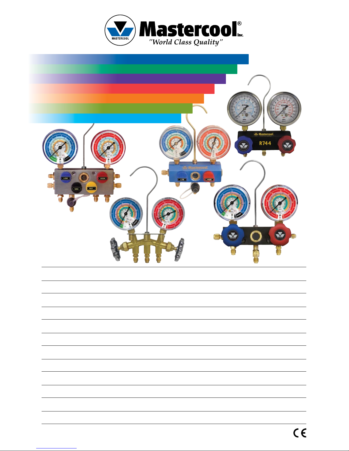
OPERATING INSTRUCTIONS
CHARGING AND TESTING MANIFOLD
BEDIENUNGSANLEITUNG
DER PRÜFARMATUREN
MANUEL D’OPÉRATION
DU MANIFOLD
INSTRUCCIONES DE OPERACION
ANALIZADORES DE CARGA Y ANÁLISIS
ISTRUZIONI PER L’USO
GRUPPI MANOMETRICI
HANDLEIDING
VUL- EN TEST-MANIFOLDS
MANUAL DE OPERAÇÃO
MANIFOLDS (ANALISADOR) DE CARGA E TESTE
Deutsch
Français
Español
Italiano
English
Portuguese
Nederlands
Page 2
2 www.mastercool.com
Page 3
3www.mastercool.com
WARNING
Wear Safety Goggles
Avoid Contact with Refrigerant
NOTE (R744): CO2 systems work under extremely high pressures. Only professional technicians are
recommended to service these systems. Please use proper safety equipment while servicing.
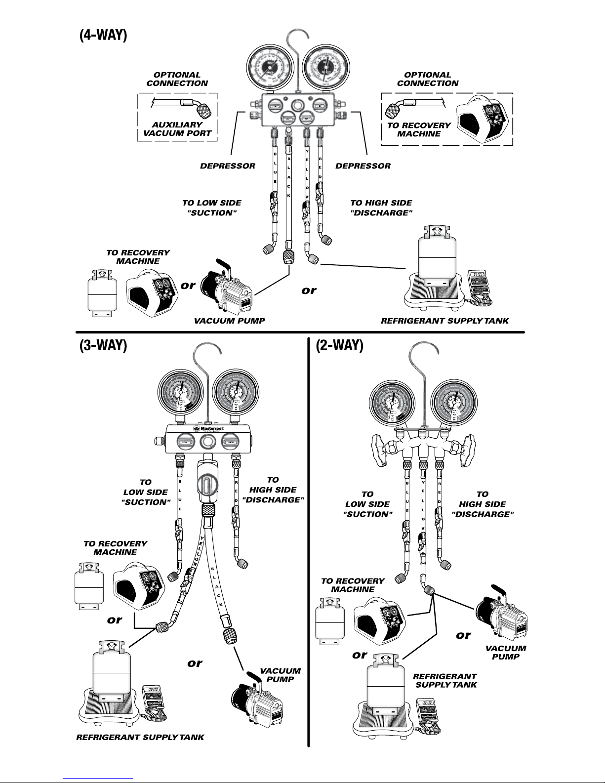
PRE-SERVICE INSTRUCTIONS
1. Close both valves on the manifold gauge set by turning the high and low knobs clockwise.
2. The gauges are correctly calibrated at the factory before shipment. If calibration is required, remove the lens and
insert a straight blade screwdriver into the adjusting screw on the gauge face.
3. Connect the (red) hose to the high port and the (blue) hose to the Low port on the manifold gauge.
TESTING AND CHARGING
To properly diagnose the problem in the R/AC system, first check the system’s overall performance. This includes monitoring the system’s pressure as well as leak testing. Your manifold gauge set will give accurate readings of your system’s
pressure.
NOTE: Be sure that the hand valves on the manifold gauge set are in the closed position. Always wear gloves and
safety goggles when working with refrigerant.
1. Remove the protective caps from the system ports. Check for leaks at the ports.
2. Connect the low side service hose (blue) to the suction side of the compressor. Connect the high side service hose
(red) to the discharge side of the compressor.
3. If using adapters, make sure that they are fully tightened and piercing the access valve. Failure to properly access the
valve core will prohibit refrigerant flow.
IMPORTANT NOTES
• A system that has been opened or one that is found to be excessively low on refrigerant pressure as a result of a leak,
must be fully evacuated by means of recycling and deep vacuum.
• A system that has been evacuated must be repaired, leak tested and evacuated to a required level of vacuum.
• If charging on the liquid or high side, use only the high side valve on the manifold gauge set. Make sure the low side
valve is closed.
• After charging, test the system by turning on the engine and running the A/C with both valves closed on the manifold.
• After testing, disconnect the hoses from the system and make sure to use a recovery/recycling machine to evacuate
any refrigerant remaining in the hoses or manifold.
English
WARNING: This product can expose you to chemicals including lead, which is known to the State of California to cause cancer and birth defects or other
reproductive harm. For more information go to www.P65Warnings.ca.gov.
Page 4
4 www.mastercool.com
Page 5
5www.mastercool.com
HINWEIS (R744): CO2-Systeme arbeiten unter extrem hohen Drücken. Nur professionelle Techniker sollten diese
Systeme warten. Bitte verwenden Sie während der Wartung geeignete Sicherheitsausrüstung.
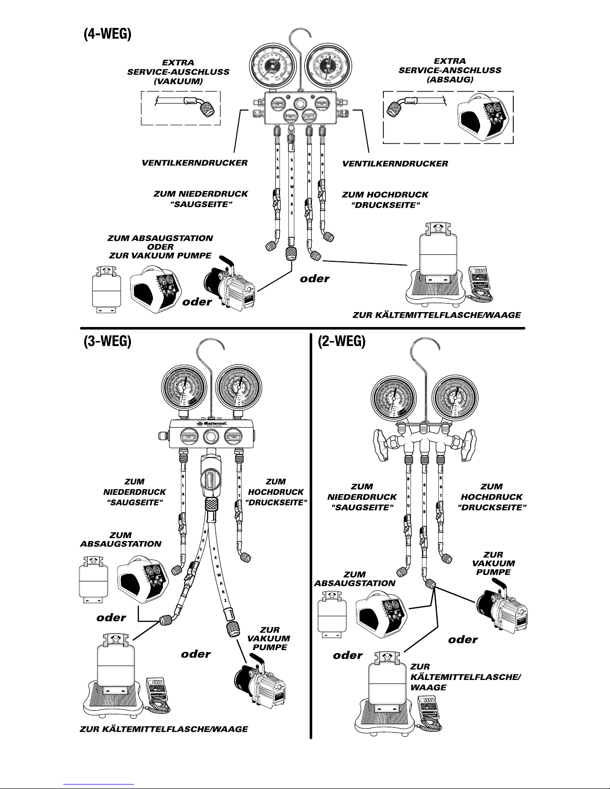
VORBEREITUNGEN
1. Hoch- und Niederdruckventile der Prüfarmatur schließen, indem man die Drehknöpfe im Uhrzeigersinn dreht.
2. Manometer werden gründlich im Werk kalibriert. Um einen Manometer zu kalibrieren, sollten eventuell Einfassungs-
und Sichtglas abgenommen werden. Ein gerader Schraubenzieher wird auf die Einstellungsschraube der Manometerfrontseite aufgesetzt.
3. Den roten Schlauch an die Hochdruckseite, bzw. den blauen Schlauch an die Niederdruckseite der Prüfarmatur
anschliessen.
TESTEN UND FÜLLEN
Um eine ordentliche Diagnose des R/AC Systems auszuführen, soll zuerst die allgemeine Leistung kontrolliert werden.
Mitinbegriffen sind dabei auch Druck und eine leckfreie K/AWichtige Anmerkungen. Diese Zustände können mit dem
Prüfarmaturmanometersatz kontrolliert werden.
ANMERKUNG: Vergewissern Sie sich, dass die manuellen Prüfarmaturventile geschlossen sind. Immer Handschuhe und Schutzbrillen tragen, wenn Sie mit Kältemittel arbeiten.
1. Schutzkappen von den Systemanschlüssen abziehen. Leckagen an den Anschlüssen kontrollieren.
2. Niederdruck Serviceschlauch (blau) an die Niederdruckseite anschließen. Hochdruck Serviceschlauch (rot) zur Hochdruckseite anschließen.
3. Bei Benutzung von Adaptern vergewissern Sie sich, dass sie fest angeschraubt sind und die Anschlussventile durchdringen Ohne korrekten Anschluss wird der Ventilkern die Kältemittelzufuhr nicht durchlassen.
WICHTIGE ANMERKUNGEN
• Eine geöffnete K/A, welche wegen einer Leckage besonders wenig Kältemitteldruck aufweist, muß völlig mit einem
Entsorgungsgerät abgesaugt, dann über eine tief Vakuumpumpe geleert werden. (Skizze C)
• Ein System, das evakuiert worden ist, muss repariert werden, auf Dichtheit geprüft und auf ein erforderliches Vakuumniveau gezogen werden.
• Vor Füllung der Hochdruckseite (flüssige Seite) ausschließlich das Prüfarmaturenhochdruckventil benutzen. Vergewissern Sie sich, dass das Niederdruckventil gesperrt ist.
• Nach der Füllung die K/A prüfen, KFZ Motor und K/A einschalten, dabei müssen beide Prüfarmaturenventile gesperrt
sein.
• Nach Prüfung muss hinterbliebene Kältemittel aus den Schläuchen abgesaugt werden, dazu müssen die Anschlussstücke vom System gelöst werden und wird ein Absauggerät benutzt werden.
Deutsch
WARNUNG: Dieses Produkt kann Sie Chemikalien einschließlich Blei, die dem Staat Kalifornien bekannt ist, um Krebs und Geburtsfehler oder andere
reproduktive Schäden zu verursachen. Weitere Informationen finden Sie unter www.P65Warnings.ca.gov.
Page 6
6 www.mastercool.com
Page 7

7www.mastercool.com
NOTE (R744): Les systèmes à CO2 fonctionnent sous des pressions extrêmement élevées. Seuls les techniciens
professionnels sont recommandés pour entretenir ces systèmes. Veuillez utiliser l’équipement de sécurité
approprié pendant l’entretien.
AVANT DE COMMENCER LES TRAVAUX
1. Fermez les deux boutons des vannes du manifold, en les tournant dans le sens de l’aiguille d’une montre.
2. Les manomètres sont correctement calibrés en usine avant expédition. Lorsqu’un calibrage est requis, utilisez un
tournevis pour régler le manométre par le vis de réglage qui se trouve sur la face du cadran.
3. Raccordez le flexible rouge du côté haute pression (HP) et le flexible bleu du côté basse pression (BP) du manifold.
TEST et REMPLISSAGE
Afin de correctement diagnostiquer un problème dans le système R/AC, vérifiez d’abord la performance en générale.
Cela comprend aussi bien la pression que la détection de fuites. Votre manifold à manomètre vous permettra une lecture
précise de la pression dans le système.
NOTEZ: Vérifiez, que les vannes manuelles sur le manifold à manomètres sont bien fermés. Portez toujours des
gants et des lunettes de sécurité en travaillant avec du réfrigérant.
1. Ôtez les capsules de protection des ports d’accès du système, et vérifiez s’il y a des fuites aux ports d’accès.
2. Raccordez le flexible de basse pression-bleu du côté aspiration du compresseur. Raccordez le flexible de haute pression-rouge du côté refoulement.
3. Lors de l’usage d’adaptateurs, vérifiez, que ceux-ci sont fermement serrés et permettent à l’obus de valve de traverser. Sinon l’obus de la valve ne permettra pas le passage du réfrigérant.
IMPORTANT
• Un système, qui a été ouvert, ou encore qui à cause d’une fuite affiche une pression très basse en réfrigérant, doitêtre entièrement vidé par recyclage et mise à vide.
• Un système qui a été évacuée doit être réparé, testé pour des fuites et tiré vers un niveau de vide prescrit.
• Si la charge se fait du côté liquide ou haute pression, utilisez uniquement la vanne de haute pression sur le manifold.
Vérifiez, que la vanne de basse pression est fermée.
• Après la charge, vérifiez en mettant en marche le moteur et l ‘A/C avec les deux vannes du manifold fermées.
• Après le test, déconnectez les flexibles du système et utilisez un appareil de récupération/recyclage pour évacuer tout
le réfrigérant restant dans les flexibles ou manifold.
Français
ATTENTION: Ce produit peut vous exposer à des produits chimiques dont le plomb, qui est connu de l’État de Californie pour causer des cancers et des
malformations congénitales ou d’autres dommages à la reproduction. Pour plus d’informations, visitez www.P65Warnings.ca.gov.
Page 8

8 www.mastercool.com
Page 9

9www.mastercool.com
NOTA (R744): Los sistemas de CO2 trabajan a presiones extremadamente altas. Se recomienda usar
profesionales calificados para darle mantención a estos sistemas. Use equipo de seguridad apropiado mientras
le da servicio a estos sistemas.
INSTRUCCIONES DE PRE-SERVICIO
1. Cerrar ambas válvulas del analizador girándolas en sentido horario.
2. Los manómetros son correctamente calibrados en fábrica antes del envío. Si su calibración fuera necesaria, retirar
las lentes quitando primero el marco de retención. Insertar la boca plana de un destornillador en el tornillo de ajuste
situado en la esfera del manómetro.
3. Conectar la manguera Roja al puerto de Alta presión y la manguera Azul al puerto de Baja presión del analizador.
PRUEBA Y CARGA
A fin de diagnosticar correctamente un problema en el sistema climático R/AC, primero verificar el rendimiento general
del sistema. Esto incluye la comprobación de la presión del sistema como la detección de fugas. Su analizador le dará
unas lecturas precisas de la presión del sistema.
NOTA: Asegúrese que las válvulas manuales del analizador están en posición de cerradas. Siempre deberá llevar
guantes y gafas de protección cuando esté trabajado con refrigerante.
1. Retirar los tapones de protección de los puertos del sistema. Comprobar si hubiera escapes en los puertos.
2. Conectar la manguera de Baja Presión (Azul) en el lado de aspiración del compresor. Conectar la manguera de Alta
Presión (Roja) en el lado de descarga del compresor.
3. Si usa adaptadores estar seguro que estén bien fijados y penetrando la válvula de acceso. De lo contrario la Válvula de
Obús no permitirá el paso del refrigerante.
NOTAS IMPORTANTES
• Un sistema conteniendo poco refrigerante causado por una abertura o un escape dará lugar a vaciar el sistema por
reciclaje y puesta en vació.
• Un sistema que ha estado eliminando refrigerante debe ser reparado, probado contra fugas y eliminado a un nivel de
vacío requerido.
• Si la carga del líquido se hiciera solamente por la Alta presión, active en este caso solamente la válvula de Alta presión
del analizador. Asegúrese que la válvula de Baja presión esta cerrada.
• Comprobar el sistema después de la carga, haciendo girar el motor y la climatización con las dos válvulas del analizador cerradas.
• Después de la comprobación, desconecte las mangueras del sistema y asegúrese de usar un equipo de recuperación /
reciclaje para evacuar todo el fluido refrigerante remanente en las mangueras o analizador.
Español
ADVERTENCIA: Este producto puede exponerlo a productos químicos como el plomo, que es conocido por el Estado de California como causante de cáncer y
defectos congénitos u otros daños reproductivos. Para obtener más información, visite www.P65Warnings.ca.gov.
Page 10

10 www.mastercool.com
Page 11

11www.mastercool.com
NOTA (R744): I sistemi a CO2 funzionano a pressioni estremamente elevate. Solo i tecnici professionali sono
raccomandati per il servizio di questi sistemi. Utilizzare l’attrezzatura di sicurezza appropriata durante la
manutenzione.
ISTRUZIONI PRE-SERVICE
1. Chiudere entrambe le valvole sul manometro collettore ruotando le manopole HIGH e LOW in senso orario.
2. Gli indicatori sono calibrati correttamente in fabbrica prima della spedizione. Se è necessaria una calibrazione, rimuovere l’obiettivo e inserire un cacciavite a lama piatta nella vite di regolazione sul manometro.
3. Collegare il tubo rosso alla porta di Alta pressione e il tubo Blu alla porta di Bassa pressione.
COLLAUDO E CARICA
Per diagnosticare correttamente il problema nel sistema A/C, controllare in primo luogo la performance complessiva del
sistema. Questo include il monitoraggio della pressione del sistema, nonché prove di tenuta. Il tuo gruppo manometrico
darà letture accurate della pressione del sistema.
NOTA: Assicurarsi che le valvole manuali sul gruppo manometrico siano nella posizione di chiusura. Indossare
sempre guanti e occhiali di sicurezza quando si lavora con il refrigerante.
1. Rimuovere i cappucci protettivi ddagli attacchidi sistema. Controllare eventuali perdite neglia attacchi.
2. Collegare il tubo di servizio lato basso (blu) sul lato aspirazione del compressore. Collegare il tubo di servizio High Side
(rosso) sul lato di scarico del compressore.
3. Se si utilizza adattatori, assicurarsi che siano completamente serrati e penetranti la valvola di accesso. La cattiva
connessione alla valvola bloccehra’ il flusso di refrigerante.
NOTE IMPORTANTI
• Un sistema che è stato aperto o che è risultato con una pressione molto bassa a causa di una perdita, deve essere
completamente evacuato mediante riciclo e profondo vuoto.
• Un sistema che è stato evacuato deve essere riparato, testato ed evacuato a un livello richiesto di vuoto.
• Se si carica sul lato liquido o di alta, usare solo la valvola di high-side sul gruppo manometrico. Assicurarsi che la
valvola di bassa pressione sia chiusa.
• Dopo la carica, testare il sistema accendendo il motore e il funzionamento con entrambe le valvole chiuse sul collettore.
• Dopo il test, staccare i tubi flessibili del sistema e assicurarsi di utilizzare una macchina di recupero / riciclaggio per
evacuare il refrigerante rimasto nei tubi o nel collettore.
Italiano
ATTENZIONE: Questo prodotto può esporre a prodotti chimici compreso il piombo, che è noto allo Stato della California per causare cancro e difetti di nascita o
altri danni riproduttivi. Per ulteriori informazioni visitare il sito www.P65Warnings.ca.gov.
Page 12

12 www.mastercool.com
Page 13

13www.mastercool.com
OPMERKING (R744): CO2-systemen werken onder extreem hoge drukken. Alleen professionele technici worden
aanbevolen om deze systemen te onderhouden. Gebruik tijdens het onderhoud de juiste veiligheidsuitrusting.
ALVORENS TE BEGINNEN
1. Sluit alle kranen op de manifold, in uurwijzerzin.
2. De manometers werden geijkt in de fabriek vóór verscheping. Indien ijking vereist is, haal dan het plastiek topje uit de
lens of verwijder de lens zelf en breng de naald op 0 met een schroevendraaier.
3. Sluit de rode vulslang aan de hogedrukzijde en de blauwe aan de lagedrukzijde van manifold aan.
CONTROLE EN VULLING
Teneinde een correcte diagnose van het probleem van de koel- of airco-installatie te kunnen maken, test eerst de
algemene prestatie ervan. Controleer drukken en test op lekken. Uw manifold zal de reële drukken van de installatie
weergeven.
NOTA: Let op dat de kranen op de manifold gesloten zijn. Draag steeds handschoenen en een veiligheidsbril
wanneer u met koelmiddel werkt.
1. Verwijder de kapjes op de hoge en lage drukaansluitingen van de installatie. Controleer deze op lekken.
2. Sluit de blauwe slang aan de zuigzijde van de compressor en de rode slang aan de drukzijde.
3. Wanneer u adapters gebruikt, controleer of deze goed afdichten en de ventielkern in de aansluiting volledig indrukken.
Indien onvoldoende opening, zal het koelmiddel niet kunnen vloeien.
BELANGRIJK
• Een installatie die geopend geweest is of zeer weinig druk vertoont ten gevolge een lek, moet volledig van koelmiddel
geleegd met een afzuigunit én diep vacuüm getrokken worden.
• Een installatie die geleegd werd moet gerepareerd worden, op lekken getest en gevacuümeerd tot een vereist vacuüm
vooraleer terug te vullen.
• Indien u vult langs de vloeistofzijde of hoge druk, gebruik dan enkel de rode kraan op de manifold. De blauwe kraan
blijft dan dicht.
• Na het vullen, test de installatie door ze aan te zetten. Laat ze werken, terwijl beide kranen van de manifold gesloten
zijn.
• Hierna koppelt u beide slangen los van de installatie en gebruikt u een afzuigunit om het laatste koelmiddel uit manifold en leidingen te halen.
Nederlands
WAARSCHUWING: Dit product kan u blootstellen aan chemicaliën, waaronder lood, die bekend staat aan de staat Californië om kanker en geboorteafwijkingen
of andere voortplantingsschade te veroorzaken. Voor meer informatie, ga naar www.P65Warnings.ca.gov.
Page 14

14 www.mastercool.com
LOW
VAC
REF
HIGH
OU
OU
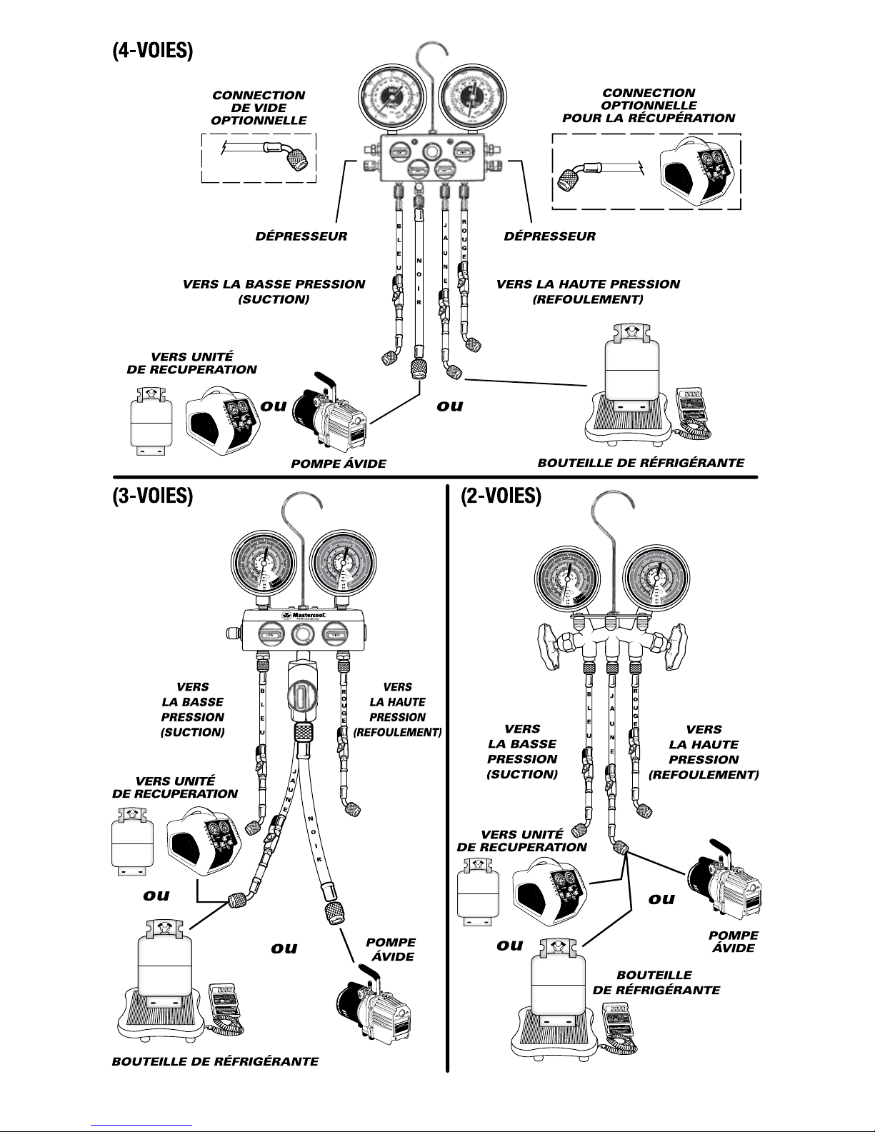
DEPRESSOR DEPRESSOR
LADO DE ALTA
"DESCARGA"
TO
HIGH SIDE
"DISCHARGE"
TO
HIGH SIDE
"DISCHARGE"
LADO DE BAIXA
"SUCÇÃO"
LADO DE BAIXA
"SUCÇÃO"
LADO DE BAIXA
"SUCÇÃO"
ENTRADA AUXILIAR
PARA VÁCUO
CONEXÃO
OPCIONAL
CONEXÃO
OPCIONAL
BOMBA DE VÁCUO TANQUE DE FLUIDO REFRIGERANTE
BOMBA
DE VÁCUO
BOMBA
DE VÁCUO
OU
OU
PARA MAQUINA DE RECOLHIMENTO
(4 VIAS)
(2 VIAS)(3 VIAS)
PARA MAQUINA
DE RECOLHIMENTO
PARA MAQUINA
DE RECOLHIMENTO
OU
LOW
HIGH
PARA MAQUINA
DE RECOLHIMENTO
w
w
w
.
m
a
s
t
e
r
c
o
o
l
.
c
o
m
100
200
300
400
500
600
700
800
0
20
15
10
5
0
25
30
35
40
45
50
55
M
A
S
T
E
R
C
O
O
L
psi
Mpa
bar
0.5
1.5
2.0
2.5
3.0
3.5
4.0
4.5
5.0
1.0
M
A
S
T
E
R
C
O
O
L
bar
psi
0
-30
25
100
75
50
125
150
175
200
225
250
275
300
500
15
20
34.5
10
5
0
-1
0.5
1.0
1.5
2.0
0
Mpa
R
in
.Hg
-.1
SUCTION PRESSURE
CIRCUIT
BREAKER
DISCHARGE PRESSURE
TO RECOVER
TO PURGE
RECOVER
OPEN
PURGE
CLOSED
E (START)
POWER
inlet
w
w
w
.
m
a
s
t
e
r
c
o
o
l
.
c
o
m
100
200
300
400
500
600
700
800
0
20
15
10
5
0
25
30
35
40
45
50
55
M
A
S
T
E
R
C
O
O
L
psi
Mpa
bar
0.5
1.5
2.0
2.5
3.0
3.5
4.0
4.5
5.0
1.0
M
A
S
T
E
R
C
O
O
L
bar
psi
0
-30
25
100
75
50
125
150
175
200
225
250
275
300
500
15
20
34.5
10
5
0
-1
0.5
1.0
1.5
2.0
0
Mpa
R
in.Hg
-.1
SUCTION PRESSURE
CIRCUIT
BREAKER
DISCHARGE PRESSURE
TO RECOVER
TO PURGE
RECOVER
OPEN
PURGE
CLOSED
E (START)
POWER
inlet
R
0000
w
w
w
.
m
a
s
t
e
r
c
o
o
l
.
c
o
m
100
200
300
400
500
600
700
800
0
20
15
10
5
0
25
30
35
40
45
50
55
M
A
S
T
E
R
C
O
O
L
psi
Mpa
bar
0.5
1.5
2.0
2.5
3.0
3.5
4.0
4.5
5.0
1.0
M
A
S
T
E
R
C
O
O
L
bar
psi
0
-30
25
100
75
50
125
150
175
200
225
250
275
300
500
15
20
34.5
10
5
0
-1
0.5
1.0
1.5
2.0
0
Mpa
R
in.Hg
-.1
SUCTION PRESSURE
CIRCUIT
BREAKER
DISCHARGE PRESSURE
TO RECOVER
TO PURGE
RECOVER
OPEN
PURGE
CLOSED
E (START)
POWER
inlet
OU
w
w
w
.
m
a
s
t
e
r
c
o
o
l
.
c
o
m
100
200
300
400
500
600
700
800
0
20
15
10
5
0
25
30
35
40
45
50
55
M
A
S
T
E
R
C
O
O
L
psi
Mpa
bar
0.5
1.5
2.0
2.5
3.0
3.5
4.0
4.5
5.0
1.0
M
A
S
T
E
R
C
O
O
L
bar
psi
0
-30
25
100
75
50
125
150
175
200
225
250
275
300
500
15
20
34.5
10
5
0
-1
0.5
1.0
1.5
2.0
0
Mpa
R
in.Hg
-.1
SUCTION PRESSURE
CIRCUIT
BREAKER
DISCHARGE PRESSURE
TO RECOVER
TO PURGE
RECOVER
OPEN
PURGE
CLOSED
E (START)
POWER
inlet
R
0000
R
0000
TANQUE DE FLUIDO REFRIGERANTE
TANQUE DE
FLUIDO REFRIGERANTE
Page 15

15www.mastercool.com
NOTA (R744): os sistemas de CO2 funcionam sob pressões extremamente elevadas. Apenas técnicos
profissionais são recomendados para atender esses sistemas. Use equipamento de segurança adequado durante
a manutenção.
INSTRUÇÕES INICIAIS
1. Feche ambas válvulas do conjunto manifolds girando horário os registros de Alta e Baixa
2. O manômetros são corretamente calibrados na fabrica antes da entrega. Caso a calibração sejá necessaria, remova a
tampa e com uma chave de fenda ajuste o ponteiro ao zero girando o parafuso de regulagem.
3. Conecte a mangueira vermelha na entrada de alta e a mangueira azul na entrada de baixa do manifolds.
CARGA E TESTE
Para diagnosticar o problema no sistema de refrigeração e ar condicionado, primeiro verifique o rendimento de todo o
sistema. Isto inclui monitoramento das pressões do sistema e teste de vazamento. Seu manifolds ira lhe dar a leitura
precisa das pressões.
NOTA: Esteja seguro que as valvulas do conjunto manifolds estejam na posição fechada. Sempre vista luvas e
óculos de segurança para trabalhar com refrigerante.
1. Remova as tampas protetoras das entradas do sistema. Verifique se nao existe vazamentos nestas entradas.
2. Conecte a mangueira azul no lado de sucção (baixa) do compressor. Conecte a mangueira vermelha no ladao de
descarga (alta) do compressor.
3. Caso use adaptador, tenha certeza que estes estejam completamente apertados e abriram a valvula de serviço. Falha
na conexão de acesso irão impedir que o refrigerante flua ate o manometro.
NOTAS IMPORTANTES
• Um sistema que tenha sido aberto ou encontrado uma pressão excessivamente baixa de refrigerante como resultado
de vazamentos deve ser completamente esvaziado atraves de recicladora e feito um vacuo profundo.
• Com o sistema vazio este deve ser reparado, feito teste de vazamento e feito vacuo profundo até o valor exigido pelo
fabricante.
• Caso a carga seja feito em liquido ou lado de alta, use somente a valvula de alta do manifolds. Certifique-se que o
lado de baixa esteja fechado. Apos a carga, teste o sistema ligando o motor e ligando o sistema de A/C com ambas as
válvulas do manifolds na posição fechada.
• Após o teste, disconecte as mangueiras do sistema e use a maquina de recolhimento e reciclagem para recolher
qualquer residuo de refrigerante que tenha permanecido na mangueira e no manifolds.
Portuguese
AVISO: Este produto pode expô-lo a produtos químicos, incluindo chumbo, que é conhecido pelo estado da Califórnia para causar câncer e defeitos congênitos
ou outros danos reprodutivos. Para mais informações, visite www.P65Warnings.ca.gov.
Page 16

16 www.mastercool.com
BRASS & ALUMINUM GAUGE SET PARTS
(2-WAY)
Fig. Description Part# Fig. Description Part#
1.
Piston Seal Assembly w/ O-rings (2
pcs.)
34216
10. Knob only
93211
2. Piston Seal O-ring (2 pcs.)
34215
11. Stem, Nut and Stem O-ring
85218
3. Stem and Nut
34218
12. Stem O-ring (2 pcs)
85217
4. Handwheel
34212
13. Piston Seal O-ring (4 pcs.)
85215
5. Stem Assembly W/Knob (2 pcs.)
34219
14. Piston Seal Assembly W/O-rings (2 pcs.)
85216
6.
High Side Gauge (Red)
Low Side Gauge (Blue)
-----
-----
(4-WAY)
7. O-ring for Shut Off Valve
90336
15. Repair Kit for 4-Way Ball Valve Manifold
95215
8. Gasket for Hose Assembly
42010 (3-WAY)
9. Stem Assembly w/Knob (2 pcs.)
93210
16. Repair Kit for 3-Way Ball Valve Manifold
58218
MESSING UND ALUMINIUM MANOMETER SÄTZE TEILE
(2-WEG)
Skizze Beschreibung Teil N
o
Skizze Beschreibung Teil No
1.
Kolbendichtungsmontage, O-Ringe
(2 Stück)
34216
10. Nuss
93211
2. Kolben O-Ringe (2 Stück)
34215
11. Stiel, Nuss und Stiel O-Ring
85218
3. Stiel und Nuss
34218
12. Stiel O-Ring (2 Stück)
85217
4. Handrad
34212
13. Kolben O-Ring (4 Stück)
85215
5. Stiel Montage mit Knöpfen (2 Stück)
34219
14.
Kolbendichtung Montage mit O-Ring
(2 Stück)
85216
6.
Hochdruck Seite Man. (rot)
Niederdruck Seite Man. (blau)
-----
-----
(4-WEG)
7. O-Ringe für Arretierventile
90336
15.
Reparationskit für 4-Weg
Monteurhilfe mit Kugelventil
95215
8. Dichtung für Schlauchmontage
42010 (3-WEG)
9. Stiel Montage mit Nuss, (2 Stück)
93210
16.
Reparationskit für 3-Weg
Monteurhilfe mit Kugelventil
58218
Page 17

17www.mastercool.com
MANOMETRE EN LAITON OU EN ALUMINIUM PIECES
(2-VOIES)
Réf. Description Pièce N
o
Réf. Description Pièce N
o
1.
Assemblage de joints pour piston et
joints toriques (2 pcs)
34216
10. Bouton seul
93211
2. Joints toriques pour piston (2 pcs)
34215
11. Tige, écrou et joint torique
85218
3. Tige avec écrou
34218
12. Joint torique pour tige (2 pcs)
85217
4. Volant-robinet
34212
13. Joint tor. pour piston (4 pcs.)
85215
5. Assemblage tige/bouton (2 pcs.)
34219
14.
Assemblage de joints pour piston et
joints toriques (2 pcs)
85216
6.
Manomètre haute. press. (Rouge)
Manomètre basse press. (Bleu)
-----
-----
(4-VOIES)
7. Joint torique pour vanne d’arrêt
90336
15.
Kit de réparation pour manifold à 4
vannes à boule
95215
8. Joints pour raccords de flexible
42010 (3-VOIES)
9. Assemblage de tige/boutons (2 pcs)
93210
16.
Kit de réparation pour manifold à 3
vannes à boule
58218
PIEZAS Y ACCESORIOS PARA ANALIZADORES DE LATÓN Y ALUMINIO
(2-VIAS)
Fig. Descripción Ref.# Fig. Descripción Ref.#
1.
Conjunto de juntas del pistón con juntas
tóricas (2 pzas)
34216
10. Pomo solo
93211
2. Junta tórica del pistón (2 pzas)
34215
11. Vástago tuerca y junta tórica
85218
3. Vástago con tuerca
34218
12. Junta tórica del vástago (2 pzas)
85217
4. Volante
34212
13. Juntas tóricas del pistón (4 pzas)
85215
5. Conj. Vástago con pomo (2 pzas.)
34219
14.
Conj. de juntas pistón con Juntas
tóricas (2 pzas)
85216
6.
Manómetro alta presión (Rojo)
Manómetro baja presión (Azul)
-----
-----
(4-VIAS)
7. Junta tórica para válvula de corte autm.
90336
15.
Kit de reparacion para analizador 4 vias
con valvula de bola
95215
8. Junta para racor manguera
42010 (3-VIAS)
9. Conjunto vástago con pomo (2 pzas)
93210
16.
Kit de reparacion para analizador 3 vias
con valvula de bola
58218
Page 18

18 www.mastercool.com
MESSING & ALUMINIUM MANIFOLD ONDERDELEN
(2-WEG)
Fig. Beschrijving Art# Fig. Beschrijving Art#
1. Piston Dichting m/ O-ringen (2 st) 34216 10. Knop enkel
93211
2. Piston Dichting O-ring (2 st.) 34215 11. As, Moer en O-ring
85218
3. As en moer 34218 12. O-ring As (2 pcs)
85217
4. Draaiknop 34212 13. Piston Dichting (4 pcs.)
85215
5. As met Knop (2 pcs.)
34219
14. Piston Dichting (2 st.)
85216
6.
Hoge Druk Manometer (Rood) -- Lage Druk Manometer (Blauw) ---
-----
-----
(4-WEG)
7. O-Ring voor Kraan
90336
15.
Reparatiekit voor 4-Weg
Kogelkraan-Manifold
95215
8. Dichting voor Vulslang
42010 (3-WEG)
9. As set met knop
93210
16.
Reparatiekit voor 3-Weg
Kogelkraan-Manifold
58218
GRUPPO MANOMETRICO IN OTTONE
MESSING MANIFOLD
2
5
1
3
4
6
7
8
9
10
11
12
13
14
GRUPPO MANOMETRICO IN ALLUMINIO
ALUMINUM MANIFOLD
15
(4-WEG)
(3-WEG)
16
0
100
90
80
70
60
50
40
30
20
10
110
130
120
140
150
350
PSI
BAR
R134a
MC
1
2
3
4
5
6
7
8
9
10
18
0
0
10
-10
-20
-30
20
30
40
10
20
-20
30
40
50
60
70
80
90
100
110
-40
F
In
Hg
VAC
10
20
30
(4-VIE)
(3-VIE)
GRUPPI OTTONE E ALLUMINIO- PARTI DI RICAMBIO
(2 VIE)
Fig. Descrizione Codice# Fig. Descrizione Codice#
1.
Pistone e Guarnizione di montaggio con
O-ring (2 pz.)
34216
10. Manopola
93211
2. O-ring del pistone (2 pz.)
34215
11. Stelo, Dado e O-ring
85218
3. Stelo e dado
34218
12. Stelo e O-ring (2 pz)
85217
4. Volantino
34212
13. O-ring (4 pz.)
85215
5. Stelo completo con manopola (2 pz.)
34219
14.
Pistone Guarnizione di montaggio con
O-ring (2 pz.)
85216
6.
Manometro di alta (Rosso)
Manometro di bassa (Blu)
-----
-----
(4 VIE)
7. O-ring per Valvola di arresto
90336
15.
Kit di riparazione per gruppo manometrico 4 vie con valvole a sfera3 vie
95215
8. Guarnizione per tubo di montaggio
42010 (3 VIE)
9. Stelo completo con manopola (2 pz.)
93210
16.
Kit di riparazione per gruppo manometrico 3 vie con valvole a sfera
58218
Page 19

19www.mastercool.com
SOBRESSALENTES PARA MANIFOLDS LATÃO & ALUMINIO
(2 VIAS)
Pos. Descrição Código Pos. Descrição Código
1.
Vedação do pistão montado com anel
O-ring (2 pçs)
34216
10. Manipulo somente
93211
2. Vedação O-ring do pistão (2 pçs)
34215
11. Haste, porca e O-ring
85218
3. Haste e porca
34218
12. Anel o-ring haste (2 pçs)
85217
4. Manipulo
34212
13. O-ring vedação pistão (4 pçs)
85215
5. Haste montado com manipulo (2 pçs)
34219
14.
Vedação do pistão montado com anel
O-ring (2 pçs)
85216
6.
Manômetro Lado de Alta (Vermelho)
Manômetro Lado de Baixa (Azul)
-----
-----
(4 VIAS)
7. O-ring para valvula de fechamento
90336
15.
Kit manutenção para Manifolds 4 vias
valvula bola
95215
8. Vedação para mangueira
42010 (3 VIAS)
9. Haste montado com manipulo (2 pçs)
93210
16.
Kit manutenção para Manifolds 3 vias
valvula bola
58218
Manifold Latão
2
5
1
3
4
6
7
8
9
10
11
12
13
14
Manifold Alumínio
15
(4 VIAS)
(3 VIAS)
16
0
100
90
80
70
60
50
40
30
20
10
110
130
120
140
150
350
PSI
BAR
R134a
MC
1
2
3
4
5
6
7
8
9
10
18
0
0
10
-10
-20
-30
20
30
40
10
20
-20
30
40
50
60
70
80
90
100
110
-40
F
In
Hg
VAC
10
20
30
Page 20

20 www.mastercool.com
93103-INST-INTL
USA
(973) 252-9119
Belgium
+32 (0) 3 777 28 48
Brasil
+ 55 (11) 4407 4017
 Loading...