

Page 1
3) No coloque material pesado sobre el cable eléctrico ó no deje que este sea retorcido.
4) No utilize enchufes ó tomas rotos.
5) No desconécte enchufes con las manos mojadas.
6) No conécte ó desconécte enchufes, ni encienda interruptores, donde pueda haber
presencia de gases inflamables.
COMPONENTES DE LA BOMBA
Tapa de escape de gases
Accesorio de escape de
gases
Mira de cristal
Tanque de aceite
Válvula de
drenaje de
aceite
Asa
Accesorio de admision
Interruptor de
encendido
Cuvierta del
ventilador
Motor
Base lamina tablero
DEVOLUCIÓN DE LA BOMBA A FÁBRICA
Rogamos envíen un fax solicitando un número de Autorización de Devolución al: 00 1 - 973-252-2455.
Este procedimiento afecta tanto a los productos en garantía como los que no estén en garantía! Las
Bombas devueltas para mantenimiento sin número de autorización de devolución no serán aceptadas.
En su fax, rogamos incluyan su Nombre, Dirección y Número de Teléfono y una descripción detallada
del problema. Nos pondremos en contacto con usted para tratar del problema y determinar si debe
devolver su Bomba o si podemos resolver la avería por teléfono. En caso de que tuviera que devolver
su Bomba, le haríamos llegar un No RMA.
Entonces, rogamos sigua las siguientes instrucciones:
• Drenar el aceite, taponar todos los puertos y ponga cinta adhesiva sobre el puerto d escape situado
al final de a empuñadura de la Bomba. Si faltara hacer lo indicado, su Bomba no seria admitida y le
sería devuelta!!
• Usar la caja original de expedición y sus embalajes si son disponibles. Daños de expedición son
imposible de reclamar en maquinaria usada.
GARANTÍA LIMITADA
Mastercool inc. Garantiza durante un año sus Bombas de Vacío contra todo defecto de piezas
o mano de obra. Esta garantía no cubre los fallos debidos a abusos, uso impropio o deterioro
progresivo y rotura. La garantía tan solo cubre al propietario original y es efectiva en la fecha
de compra. EL SERVICIO DE GARANTÍA ES PROPORCIONADO ÚNICAMENTE POR FÁBRICA
Rogamos contactar con el departamento posventa para recambios o para obtener el número
autorización de devolución para una reparación en garantía.
USA
Phone: (973) 252-9119
Belgium
Telefon + 32 (0) 3 777 28 48
2V-INT-INST
www.mastercool.com
16
English
Deutsch
Français
Español
Instruction Manual VACUUM PUMPS
In order to make the best
use of your investment,
familiarize yourself with the
new features and operating
instructions before
starting pump. Routine care
and maintenance of your
vacuum pump will give you
years of reliable service.
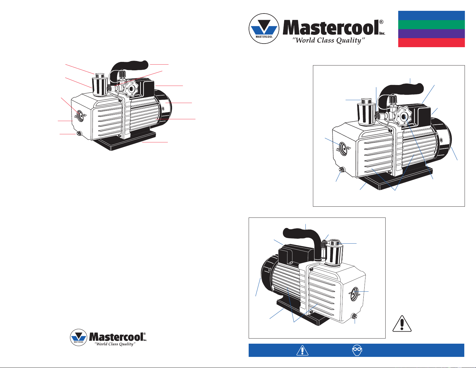
FEATURES
• An air passage prevents
pump oil from returning
to contaminate vacuum
vessel and pipeline after
the pump stops.
• A built-in device
eliminates oil mist and an
oil-gas separator at the
air exhaust outlet takes
care of oil contamination in the air exhaust.
1 STAGE
Thermally Protected
Motor with On/Off
Rocker Switch.
High Volume Fan
Provides Cool
Air to Motor &
Pump.
Large, Light Weight
Reinforced Base for
Stable Positioning.
Non-slip Cushion Handle.
Cooling Fins to Keep
Temperature Cooler During
Extended Motor Operation.
2 STAGE (DUAL VOLTAGE CAPABILITY)
Non-slip Cushion Handle.
Cooling Fins to Keep Temperature
Cooler During Extended Motor
Operation.
Vapor Discharge/
Oil Fill Port. Easily
Removable. Contains
Internal Check Valve
to Prevent Escape of
Liquid Oil.
Large
Oil Level
Sight
Glass with
Max/Min
Oil Level
Indicator.
Easily Accessible
Oil Drain Valve.
Gas Ballast Valve Helps Prevent
Oil Contamination Caused By
High Moisture.
Large, Light Weight
Reinforced Base for
Stable Positioning.
• Specially designed for low
Includes T-Fitting
with 1/4” Flare and
1/2” ACME Ports.
Vapor Discharge/
Oil Fill Port. Easily
Removable. Contains
Internal Check Valve
to Prevent Escape of
Liquid Oil.
Large
Oil Level
Glass with
Max/Min
Oil Level
Indicator.
temperature and low voltage
conditions to guarantee
normal starting in winter;
≥41˚F (≥5˚C) temperature
and ±10% rated voltage.
• Pump runs with extremely
high ultimate vacuum and low
noise.
EACH VACUUM PUMP HAS BEEN
Sight
FACTORY TESTED FOR CFM AND
MICRON PERFORMANCE.
DO NOT ATTEMPT TO
Easily Accessible
Oil Drain Valve.
OPERATE WITHOUT
USING OIL!!!
WARNING! WEAR SAFETY GLASSES
Thermally Protected Motor
with On/Off Rocker Switch.
Protected Slide Switch
to Change Operating
Voltage between
115V/50/60HZ &
22OV/50/60HZ
High Volume Fan
Provides Cool Air to
Motor & Pump
Manifold Valve Isolates
Pump from the System
Testing for Leaks.
Includes 3 Inlet Ports,
1/4”, 3/8” SAE and 1/2”
ACME.
1
Page 2
Use oil specifically refined for Deep Vacuum Pumps. Use of oil not refined for Deep
Vacuum Pumps and/or operating with contaminated oil will void warranty.
1. OIL FILL
This vacuum pump has been tested at the factory and shipped with only trace amounts of oil. OIL
MUST BE ADDED BEFORE OPERATING! Failure to add oil will damage cartridge and void warranty!
a. Make sure the oil drain valve located below the front casing is closed before attempting to add
oil.
b. Remove the oil fill plug from the top of pump and insert the oil bottle into the fill port.
c. Slowly add oil until oil level rises to the top of the Oil Level Line. Do not overfill with oil!
d. Replace the oil fill plug.
OIL CAPACITY:
3 CFM 1 Stage 13.5 OZ / 400 ML
3 CFM 2 Stage 13.5 OZ / 400 ML
6 CFM 1 Stage 15.2 OZ / 450 ML
6 CFM 2 Stage 13.5 OZ / 400 ML
10 CFM 2 Stage 19.3 OZ / 570 ML
2. CHECKING OIL LEVEL
a. Open the gas ballast valve (small brass fitting located next to the handle) one turn. Do not
remove! (AVAILABLE ON 2 STAGE PUMPS ONLY)
b. Start pump and run with intake port capped for about two minutes. Observe the oil level with
the pump running. The oil level in the sight glass should be even with the level line.
c. If the level is low, open the intake port and run pump for 15 seconds, stop pump and observe
oil level again. Add a small amount of oil as needed.
3. GAS BALLAST VALVE (2 STAGE MODELS)
The gas ballast valve must be partially opened for the first part of the evacuation procedure.
After about two minutes close the valve and continue the evacuation procedure to reach ultimate
vacuum. Failure to close the valve during high vacuum operation will result in poor vacuum
performance.
During the first stages of evacuation, vapors are highly concentrated. Unfortunately, some vapors
will condense into a liquid and mix with the oil, thus reducing the oil’s ability to produce a deep
vacuum. The GAS BALLAST VALVE emits a controlled amount of dry air into the pump
during compression to minimize condensation and keep oil relatively clean during the first part of
the evacuation. Periodically remove the Gas Ballast Valve Needle and clean or replace the O-ring.
Clean mating surfaces and lightly coat with vacuum pump oil before securely retightening.
4. CHANGING OIL
In order to reach the deep vacuum required, your vacuum pump needs clean, moisture-
free oil during evacuation. Dirty oil becomes a mixture of corrosive acids and water that effects
the pump’s ability to pull a deep vacuum. Left sitting in the pump, this sludge will rust and erode
internal surfaces shortening the pump’s life.
Care should be taken to avoid contact of oil with skin or eyes. OIL MAY BE HOT! Used oil
should be properly disposed of in a leakproof corrosive-resistant container according to
2
a. Después de cada vaciado cuando la Bomba esta caliente y el aceite es menos denso tomar
una pequeña muestra de aceite del puerto de drenaje.
b. Si el aceite esta contaminado, drenar el aceite poniendo la Bomba sobre una superficie
abriendo la válvula de drenaje . Recoger el aceite residual en un depósito y eliminarlo según las
leyes vigentes del país.
c. Si la Bomba ha estado parada por mas de un mes, el aceite es considerado como
contaminado sin tener en cuenta su apariencia y debe ser cambiado como arriba indicado.
d. Para añadir aceite, cerrar el drenaje, quitar el tapón de llenado de aceite y llenar con aceite
nuevo hasta el nivel indicado.
5. CONEXIONES DE ASPIRACIÓN
Reemplazar todos los tapones apretándolos a mano. No usar tapones con daños o sin juntas
tóricas y siempre guardar la Bomba de Vacío con sus puertos taponados para evitar la
contaminación de polvo y humedad.
6. MOTOR DE LA BOMBA
La Bomba y el Aceite deben estar en una temperatura por encima de 30˚F (1˚C). La línea
de corriente debe ser igual a las indicaciones de la placa del motor ±10%. La temperatura
normal de funcionamiento es de aproximadamente 70oC 160˚F (71˚C), lo cual es caliente al tocar!
La línea de corriente y la temperatura ambiente afectara un poco a la temperatura normal de
funcionamiento. Su Bomba de Vacío esta diseñada para un uso continuo y funcionara sin
recalentarse durante mucho tiempo. El motor esta provisto de una protección automática
contra sobrecarga. Si el motor no volviera a arrancar la Bomba después del paro, podría ser
debido al protector térmico. Desconectar la Bomba del sistema, esperar unos 15 minutos a
que el motor se refrigere y luego pruebe de nuevo.
horizontal y
ADVERTENCIA:
1) No evacue combustible, explosivo ó gases venenosos
2) No evacue gases que oxiden el metal ó que reaccionen quimicamente con el aceite de las bómbas
3) La temperatura de evacuación del gas no devera exceder 176˚F (80˚C) y la temperatura ambiente
sera 41˚F ~ 140˚F (5˚C ~ 60˚C).
4) No deve de operarse sin haber puesto aceite previamente
5) No toque la bómba, pues la superficie de esta se calienta durante la operación
6) No bloquee la salida de aire.
PRECAUCION:
Para reducir el peligro de un shock eléctrico, mantenga la bómba en un sitio cubierto y no la exponga
a la lluvia.
PELIGRO:
1) Con un tomacorriente conectado a tierra, el voltaje de operación estara clasificado en ± 10%; El
recipiente deverá estar bien fundamentado, ó bien una descarga eléctrica puede ser causada. El
cable eléctrico ó el enchufe requeriran reparación ó reemplazo, no conecte un cable de tierra a
ningun conector adaptador plano.
con aislante es el cable de tierra.Si usted no puede entender completamente, estas instrucciones, y
tiene dudas para comprobar como una buena conección a tierra es hecha,consulte con un
electricista profesional ó un experto en reparaciones eléctricas. No cambie la estructura del
conector adaptador que viene ensamblado.
2) Cuando hále ó tire el enchufe para desconectar, asegurese de hacerlo del enchufe y no del cable.
Si este es de superficie verde, con ó sin raya amarilla,el cable
15
Page 3
1. LLENADO ACEITE
La Bomba de Vacío ha sido comprobada en fábrica y embarcada con muy poco aceite. Debe añadir
aceite antes de ponerla en marcha! Al no añadir aceite dañaría la bomba y anularía la garantía!
a. Asegúrese que el tapón de vaciado de aceite esté bien cerrado antes de añadir aceite.
b. Retire el tapón de llenado de aceite de la parte de arriba de la bómba, e inserte la
puerto de llenado.
c. Añadir lentamente el aceite hasta llegar al nivel marcado. No sobrellenar!
d. Recolocar el tapón de llenado de aceite.
CAPACIDAD DE ACEITE
botella en el
3 CFM 1 Etapa 13.5 OZ / 400 ML
3 CFM 2 Etapas 13.5 OZ / 400 ML
6 CFM 1 Etapa 15.2 OZ / 450 ML
6 CFM 2 Etapas 13.5 OZ / 400 ML
10 CFM 2 Etapas 19.3 OZ / 570 ML
2. VERIFICACIÓN DEL NIVEL DE ACEITE
a. Abrir de un giro la válvula de lastre (pequeño tornillo de latón situado junto a la empuñadura).
No quitarlo! (DISPONIBLE EN BOMBAS DE 2 ETAPAS UNICAMENTE)
b. Hacer funcionar la bomba con la toma de aspiración cerrada por un tapón, durante
aproximadamente dos minutos. Observar el nivel de aceite durante el funcionamiento de la
Bomba. El nivel de aceite debe estar alineado con la línea de nivel marcado a través de la
mirilla.
c. Si el nivel es bajo, abrir el puerto de aspiración y haga girar la Bomba durante 15 segundos.
Parar la Bomba y observar de nuevo el nivel de aceite. Si fuera necesario añadir una pequeña
cantidad de aceite.
3. VÁLVULA DE LASTRE (MODELOS DE 2 ETAPAS)
Para la primera parte del proceso de evacuación, la Válvula de Lastre debe estar abierta de entre 1/4
de vuelta a completamente abierta. Después de aproximadamente dos minutos cierre la válvula y
continuar el proceso de evacuación hasta obtener el máximo vacío. El no cerrar la válvula durante la
evacuación daría un pobre rendimiento.
Durante las primeras fases de evacuación, los vapores están muy concentrados.
Lamentablemente, algunos de estos vapores se condensarán en líquido y se mezclarán con el aceite,
reduciendo la capacidad del aceite en producir el vacío. La Válvula de Lastre emite una cantidad controlada de aire seco en la Bomba durante la compresión para minimizar este efecto y así conservar el
aceite relativamente limpio durante la primera parte de la evacuación.
Periódicamente retirar la Aguja de la Válvula de Lastre y limpiar o sustituir la junta tórica. Limpiar las
superficies de unión y dar una ligera capa de aceite para bomba de vacío antes de apretar.
4. CAMBIO DE ACEITE
Para poder alcanzar el vacío requerido, su Bomba de Vacío necesita un aceite limpio y sin
humedad durante su evacuación. El aceite sucio proviene de la mezcla de ácidos corrosivos y del
agua que afecta la capacidad de la Bomba en hacer el vacío. El depósito de estos residuos oxidarán y
corroerán las paredes interiores, acortando la vida de la Bomba.
Evitar todo contacto del aceite en la piel o ojos. EL ACEITE PUEDE ESTAR CALIENTE! El aceite
usado debe ser recogido en un depósito hermético y resistente a la corrosión, según las leyes y
regulaciones del país donde es utilizado el producto.
14
local regulations.
a. After every evacuation, while the pump is warm and oil is thin, take a small sample of oil from
the drain port.
b. If the oil is contaminated, drain the oil by placing the pump on a level surface and opening the
oil drain valve. Catch the waste oil in a container and properly dispose of it.
c. If the pump has been sitting for more than one month, the oil is considered contaminated
regardless of appearance and should be changed as outlined above.
d. To add oil, close drain, remove the oil fill cap and fill to the Oil Level Line with fresh oil.
5. INTAKE CONNECTIONS
Replace all caps and finger-tighten. Do not use caps with damaged or missing O-rings and
always store vacuum pump with capped ports to prevent dirt and moisture contamination.
6. PUMP MOTOR
The PUMP and OIL must be above 30˚F (1˚C). The line voltage must be equal to the rating on the
motor nameplate ±10%. Normal operating temperature is approximately 160˚F (71˚C), which is
HOT to the touch! Line voltage and ambient temperature will affect the normal operating
temperature. Your vacuum pump is designed for continuous duty and will run for extended
periods without overheating. The motor has an automatic resetting overload protection feature. If
the motor will not restart the pump after shut-off, it may have opened the thermal protection.
Disconnect the pump from the system, wait about 15 minutes for the motor to cool down and
then try again.
WARNING:
1) Do not evacuate combustible, explosive or poisonous gases.
2) Do not evacuate gases that corrode metal or react chemically with pump oil.
3) The temperature of evacuated gas shall not exceed 176˚F (80˚C) and ambient temperature
shall be 41˚F ~ 140˚F (5˚C ~ 60˚C).
4) Do not operate without oil.
5) Do not touch the machine’s hot surface during operation.
6) Do not block air outlet.
CAUTION:
To reduce the danger of electric shock, keep the pump indoors and do not expose to rain.
DANGER:
1) With a grounding socket the operating voltage is rated ±10%; Receptacle shall be well
grounded, or else electric shock may be caused. Should power cord or plug require
repair or replacement, do not connect grounded wire to any flat adapter connector. If its
surface is green, with or without yellow stripe, the insulation wire is grounding wire. If you
cannot fully understand grounding instructions and have doubt whether correct grounding is
made, check with a professional electrician or service man. Do not change the structure of
attached adapter connector.
2) When pulling out power plug, make sure to pull the plug rather than the wire.
3) Do not place heavy matter on power wire or let power wire be squeezed.
4) Do not use broken plug or socket.
3
Page 4

5) Do not pull out power plug with wet hand.
6) Do not pull out, insert power plug or turn on power switch where flammable gases may be
present.
PUMP COMPONENTS
Exhaust Cap
Exhaust Fitting
Sight Glass
Oil Tank
Drain Oil
Handle
Intake Fitting
Power Switch
Fan Cover
Motor
Base Plate Board
RETURNING A PUMP
Please fax a request for a return authorization number to 973-252-2455. This applies to both
warranty and non-warranty service!
Pumps returned for service without a return authorization number will not be accepted.
In your fax, include your NAME, ADDRESS and PHONE NUMBER along with a detailed
explanation of the problem. We will contact you (i.e. your phone number) to discuss your problem
and determine if you have to return your pump. If you have to return your pump, we will issue you
an RMA #. Then, please follow the instructions below.
• Drain oil, cap all ports and place tape over the exhaust cap. If you fail to do this, your pump will
not be accepted and it will be returned!!!
• Use the original shipping box and inserts if available. Shipping damages are impossible to claim
on used machinery.
LIMITED WARRANTY INFORMATION
The Vacuum Pumps are warranted against defects in material and workmanship for a period of
one year. This warranty does not cover failure due to abuse, improper usage, or progressive wear
and tear. Warranty becomes valid to the original owner and is effective on the purchase date.
WARRANTY SERVICE IS PROVIDED THROUGH THE FACTORY ONLY.
Please contact the service department toll free for parts, service concerns, or to obtain a return
authorization number for warranty repair.
Español
INSTRUCCIONES DE USO BOMBA DE VACÍO
A fin de hacer un mejor uso
de su inversión, familiarícese
con las nuevas características
y instrucciones de uso antes
de hacer funcionar la bomba.
Un mantenimiento y cuidados
regulares de su bomba de
vacío le dará años de
fiabilidad y buen servicio.
CARACTERISTICAS:
• El paso de aire, evita que
el aceite regrese a
contaminar, el recipiente
de vacío y la tubería
despues de que la bómba
deje de funcionar.
• Un mecanismo incorporado
elimina el vapor de aceite,
y un separador de gas aceite en la salida del tubo
de escape de aire, se ocupa
1 ETAPA
Motor termicamente
protegido, con un
interruptor
conmutador de
encendido.
Gran volumen de
aire frío, enviado
por el ventilador
hacia el motor y la
bómba.
Base grande liviana
y reforzada para una
posición estable de
la bómba.
Aza con recubrimiento
antideslizante.
Sistema de aletas
refrigerantes para mantener baja la
temperatura durante largas jornadas
de operación del motor.
Importante!:
Utilizar aceite específicamente refinado para Bombas de Vacío. El uso de aceite no
refinado para Bombas de Vacío y / o trabajando con aceite contaminado, anularía la
garantía.
2 ETAPAS (CAPACIDAD DE VOLTAJE DUAL)
Aza con recubrimiento
Válvula de lastre de gas que alluda a
prevenir la contaminación causada por la
alta humedad.
Puerto de llenado de
aceite y descarga de
vapor, facilmente
removible. Contiene
válvula de inspección
para prevenir escape de
aceite liquido.
Mira de
cristal
de gran
tamaño
con
indicadores
de nivel
de aceite
MAX/MIN
Válvula de drenaje
de aceite de facil
acceso.
Incluye accesorios en forma de
T con puertos de 1/4” campana
y 1/2” ACME.
aceite de facil acceso.
Base grande liviana
y reforzada para una
posición estable de la
bómba.
Puerto de llenado de
aceite y descarga de
vapor, facilmente
removible. Contiene
válvula de inspección
para prevenir escapa de
aceite liquido.
tamaño con
indicadores
Válvula de drenaje de
antideslizante.
Sistema de aletas refrigerantes
para mantener baja la temperatura
durante largas jornadas de
operación del motor.
Mira de
cristal
de gran
de nivel
de aceite
MAX/MIN
Motor termicamente
protegido, con un interruptor
conmutador de encendido.
Interruptor deslizante
protegido, para el
cambio de operación
de voltaje de entre
115V/50/60HZ
& 220V/50/60HZ.
Gran volumen de aire
frío enviado por el
ventilador hacia el
motor y la bómba.
Válvula de analizador
aisla la bómba del
sistema de pruebas
para escapes.
de la contaminación del aceite.
• Diseñada especialmente para
bajas temperaturas, y bajo
voltaje, condiciones que
garantizan un normal arranque
en invierno a ≥41˚F (≥5˚C) de
temperatura y un indice de
voltaje de ±10%.
• La bómba funciona con la mas
alta definición de vacío
ademas de un bajisimo ruido.
CADA BOMBA DE VACÍO
HA SIDO
COMPROBADA EN FÁBRICA PARA
CMF Y RENDIMIENTO AL MICRÓN.
EL NUMERO DE SERIE ES
REGISTRADO. RELLENE Y ENVÍE
LA GARANTÍA PARA VALIDARLA!
NO PONERLO EN MARCHA SIN
ACEITE!!!
ADVERTENCIA! USE ANTEOJOS DE SEGURIDAD
4
13
Page 5

6) Ne pas connecter ou déconnecter en présence de gaz inflammables
COMPOSANTS DE LA POMPE
Bouchon d’échappement
Raccord d’ échappement
Voyant
Réservoir d’huile
Drain d’huile
Poignée
Raccord d’entrée
Interrupteur
Couverture de
ventilateur
Moteur
Embase
POUR RENVOYER UNE POMPE À L’USINE
Veuillez s’il vous plait faxer une demande de numéro d’autorisation de renvoi au:
00 1 973-252-2455 Cela concerne aussi bien les articles garantis et non-garantis! Les pompes
renvoyées à l’entretien sans numéro d’autorisation de renvoi ne seront pas acceptées. Veuillez
détailler dans votre fax votre NOM, ADRESSE et NUMERO DE TELEPHONE et une description de la
panne. Nous vous contacterons afin de discuter votre problème et déterminerons, si vous devez oui
ou non la renvoyer, ou si nous pouvons vous dépanner à distance. Dans le cas d’un renvoi, nous vous
ferons parvenir un No RMA. Et dans ce cas veuillez suivre les instructions ci-dessous.
• Vidangez l ‘huile, fermez avec des capuchons tous les accès, et appliquez de la toile isolante
sur l’accès d’échappement situé à l’extrémité de la poignée de la pompe. Si l’expédition ne
se fait pas dans ces règles, l’envoi sera refusé et vous sera retourné!!!
• Utilisez si disponible l’emballage d’origine de la pompe. Il est impossible de réclamer
pour des dommages d’expédition, pour du matériel usagé.
GARANTIE LIMITEE
Mastercool Inc. garantit pendant un an ses pompes à vide contre tout défaut de pièces et main d
‘œuvre. Cette garantie ne couvre pas un défaut dû à l’abus ou usage de manière incorrecte, ou encore
une usure progressive. La garantie ne couvre que le propriétaire d’origine et prend effet à
la date de l’acquisition.
LA GARANTIE DE SERVICE NE PEUT- ETRE OBTENUE QUE PAR L’USINE Veuillez s’il vous plait contacter
le service après-vente afin d’obtenir un numéro d’autorisation pour retourner la pompe en réparation
sous garantie.
Gebrauchsanweisung TIEF-VAKUUM PUMPE
Bevor Sie die Pumpe
starten, lesen Sie die
Betriebsanweisung und
machen Sie sich mit der
Pumpe vertraut.
Regelmäßige Pflege und
Wartung garantiert eine
lange Lebensdauer der
Vakuum Pumpe.
EIGENSCHAFTEN
• Rückflussicherung.
Luftdurchzug verhindert
dass das Öl im System
gezogen wird.
• Ein Ölnebelabscheider
im Luftabgas entfernt den
Öldunst.
• Entworfen für niedrige
Temperatur- und
Spannungskonditionen. Im
1 STUFE
Thermisch
geschützter Motor
mit Kippschalter.
Ventilator
kühlt Motor und
Pumpe.
Verstärkte
Grundplatte
Gepolsterter Handgriff.
Kühlrippen für das
kontinuierliches Abkühlen
2 STUFEN
Ölfullstopfen /
Auspuff. Leicht
zu entfernen.
Rückflussicherung für
flüssiges Öl.
Grosses
Ölschauglas
mit MIN/MAX
Standanzeige.
Leicht erreichbarer
Ölablass-Stopfen.
T- Fitting mit 1⁄4
SAE und 1⁄2 ACME
Gewinde.
(Doppelspannung Fähigkeit (220V-110V))
Gasballastventil gewährleistet
Abscheidung von Wasserdampf
aus dem Öl.
Verstärkter Grundplatte.
Gepolsterter Handgriff.
Kühlrippen für das
kontinuierliches Abkühlen.
Winter ist normales Starten
gewährleistet; ≥41˚F (≥5˚C)
und ±10% Spannungswert.
• Die Pumpe arbeitet bei sehr
Ölfüllstopfen /
Auspuff. Leicht zu
entfernen.
Rückflussicherung für
flüssiges Öl.
hohem endgültigem Vakuum und
niedrigem Ton.
JEDE VAKUUMPUMPE WURDE IM
WERK DURCHAUS FÜR CFM UND
MIKRON LEISTUNG GETESTET. DIE
FABRIKATIONSSERIENNUMMER
Grösses
Ölschauglas
Max Stan-
WURDE REGISTRIERT. BITTE DAS
mit Min/
GARANTIEFORMULAR
AUSFÜLLEN UND ZURÜCKSENDEN
danzeige.
FÜR SOFORTIGE
GARANTIEGÜLTIGKEIT.
Ölablass-Stopfen
NICHT OHNE ÖL BENUTZEN!!!
Deutsch
Thermisch geschützter
Motor mit Kippschalter.
Ein gesicherter
Gleitschalter erlaubt
das wählen zwischen
115V/50/60HZ &
22OV/50/60HZ
Ventilator kühlt
Motor und Pumpe.
Dreiwegventil (1/4,
3/8, 1⁄2 ACME) isoliert
Pumpe vom System für
Lecktesten.
WICHTIG! : Benutzen Sie spezifisches feines Raffinerieöl für Vakuum Pumpen.
Benutzung von nicht raffinierten Ölen oder kontaminiertes Öl macht Garantie ungültig!
WARNUNG! SCHUTZBRILLE TRAGEN
12
5
Page 6

1. Ölfüllung
Diese Vakuumpumpe wurde in der Fabrik bereits getestet und mit nur einer kleinen Menge Öl
geliefert. ÖL MUSS VOR PUMPENBETRIEB NACHGEFÜLLT WERDEN! Unterlassung von
Ölnachfüllung beschädigt die Ölkartusche, und dabei wird die Garantie ungültig!
a. Vergewissern Sie sich, dass die Ölablass-Schraube, unter dem Frontgehäuse vor der
Ölnachfüllung dicht ist.
b. Ziehen Sie den Ölfüllstöpsel vom oberen Teil der Pumpe raus und positionieren Sie die Ölflasche in
die Füllstelle.
c. Langsam Öl nachfüllen bis der Ölstand sich auf die Ölstandslinie befindet. Nicht überfüllen!
d. Die große Messing Ölfüllschraube ersetzen.
ÖLKAPAZITÄT:
3 CFM 1 Stufe 13.5 OZ / 400 ML
3 CFM 2 Stufen 13.5 OZ / 400 ML
6 CFM 1 Stufe 15.2 OZ / 450 ML
6 CFM 2 Stufen 13.5 OZ / 400 ML
10 CFM 2 Stufen 19.3 OZ / 570 ML
2. Ölstand prüfen
a. Gas-Ballastventil mit einer Umdrehung öffnen (kleine Messingschraube neben dem Handgriff).
Das Ventil nicht abnehmen! (Nur bei 2 stufigen Pumpen)
b. Pumpe starten und ungefähr 2 Minuten mit bedecktem Einlassventil drehen lassen, während
dessen den Ölstand durch das Sichtglas beobachten. Der Ölstand muss sich auf der
Ölstandlinie befinden.
c. Bei niedrigen Ölstand den Einlassanschluss 15 Sekunden laufen lassen und nochmals den
Ölstand beobachten. Etwas Öl nach Bedarf nachfüllen.
3. Gasballastventil (MODELLE MIT 2 STUFEN)
Das Gas-Ballastventil muss von 1/4 bis einer völligen Umdrehung für den ersten
Evakuierungsvorgang geöffnet sein. Ventil nach ungefähr 2 Minuten schließen und weiter
evakuieren um ein maximales Vakuum zu erreichen. Schließunterlassung während der
Evakuierung könnte eine geringe Vakuumpumpenleistung ergeben.
Während der ersten Evakuierungsetappe sind die Dämpfe höchstkonzentriert. Verschiedene
Dämpfe werden flüssig und mischen sich mit Öl, daher vermindern sie die Ölfähigkeit
genügendes Vakuum zu erzeugen. Das GASBALLASTVENTIL presst unter Druck eine kontrollierte
Menge trockene Luft in die Pumpe. Das hilft die Mischung während der ersten
Evakuierungsetappe so rein wie möglich zu halten. Regelmäßig Gasballastventilnadel
herausnehmen und O-Ring reinigen oder ersetzen. Oberflächen Verbindungsstücke reinigen, leicht mit
Vakuumpumpenöl beschichten, dann wieder alle schließen.
4. ÖLWECHSEL
Um das erforderliche Vakuum zu erreichen, braucht die Vakuumpumpe reines, feuchtfreies Öl
während des Evakuierens. Schmutziges Öl erzeugt eine Mischung aggressiver Säuren und
Wasser, welche die Fähigkeit der Pumpen ein optimales Vakuum zu erhalten, beeinträchtigt.
Dieser am Pumpenboden bleibende Satz rostet und frisst die inneren Oberflächen ab und kürzt
das Pumpenleben.
Schützen Sie Ihre Augen und Haut vor Öl. DAS ÖL KÖNNTE HEISS SEIN! Benutztes
6
à la corrosion, il y a lieu ensuite de s’en débarrasser selon la loi et les réglements du pays, ou
le produit est utilisé.
a. Aprés chaque vidange, lorsque la pompe est chaude et l’huile est fine, prélevez un petit
échantillon
d’huile de vidange.
b. Si l’huile est contaminée, placez la pompe sur une surface horizontale et ouvrez le bouchon
de
vidange. Faites couler l’huile usée dans un container et débarrassez vous en selon la loi en vigueur
de votre pays.
c. Si la pompe n’a pas fonctionnée pendant plus d’un mois, l’huile est considérée comme usée,
sans
distinction d’état apparent et devrait-être changée tel qu’indiqué ci-dessus.
d. Pour ajouter de l’huile, fermez le bouchon de vidange, ôtez la capsule de remplissage et versez
de
l’huile pure jusqu’au niveau supérieur indiqué.
5. RACCORDS D’ASPIRATION
Remplacez toutes les capuchons et vissez les manuellement, n’utilisez pas des capuchons avec des
joints toriques endommagés ou manquants et rangez la pompe à vide avec ses accès fermés par des
capuchons, pour éviter, que l’humidité et souillure y pénètre.
6. MOTEUR DE LA POMPE
La pompe et l’huile doivent se trouver dans une température ambiante d’au moins 30˚F (1˚C) Le
voltage du courant fourni doit correspondre aux indications de la plaquette du moteur ±10%. La
température normale de fonctionnement est à peu près 160˚F (71˚C), c’est à dire chaud au toucher!
Voltage et température ambiante influencent quelque peu la température de fonctionnement. Votre
pompe est fabriquée pour résister à une utilisation continue et fonctionnera sans surchauffer pendant
longtemps. Le moteur est pourvu d’un système automatique de remise en fonction et protection
thermique contre une surcharge. Si le moteur ne redémarre pas la pompe après l’arrêt, le système
de protection thermique pourrait-ètre ouvert. Déconnectez la pompe du systéme, attendez environ 15
minutes pour la refroidir et réessayez.
ATTENTION:
1) Ne pas évacuer des gaz combustibles, explosifs ou toxiques.
2) Ne pas évacuer des gaz qui corrodent le métal ou qui réagissent chimiquement avec l’ huile.
3) La température du gaz évacué ne doit excéder les 80°C et la température ambiante devra êtr
e
comprise entre les 5°C et 60°C.
4) Ne pas laisser tourner à vide (sans huile).
5) Ne pas toucher les surfaces chaudes pendant l’opération.
6) Ne pas bloquer l’échappement d’air.
PRUDENCE:
Pour éviter des chocs électriques, ne pas opérer sous la pluie.
DANGER:
1) La prise de courant doit être mise à terre, pour éviter des chocs. Ne pas réparer le câble ou la fiche.
Ne pas connecter à une fiche ou prise sans mise à terre. Si sa surface est verte, avec ou sans filet
jaune, le fil isolant est la terre. En cas de doute contacter un électricien. Ne pas intervenir sur la
fiche.
2) Pour déconnecter le fiche, tirer sur la fiche et non sur le câble.
3) Ne pas poser des objets lourds sur le câble ou le pincer.
4) Ne pas utiliser une prise ou une fiche endommagée.
5) Ne pas déconnecter avec une main mouillée.
11
Page 7

1. REMPLISSAGE D’HUILE
La pompe à vide à été examinée à l’usine et expédiée avec peu d’huile. DE L’HUILE DOIT-ÊTRE
AJOUTEE AVANT D’UTILISER LA POMPE! Vous endommagerez la pompe, si vous n’ajoutez pas de
l’huile et cela annulera la garantie!
a. Vérifiez, que le bouchon de vidange d’huile soit bien fermé avant d’ajouter de l’huile.
b. Enlever le bouchon de remplissage d’huile et introduire la bouteille d’huile pour remplir.
c. Ajoutez doucement de l’huile jusqu’au niveau indiqué. Ne pas créer un trop plein.
d. Replacez et revissez la capsule de remplissage.
CAPACITÉ D’HUILE
schmutziges Öl sollte in einem korrosionsbeständigen Behälter nach gesetzlichen Vorschriften
entsorgt Werden.
a. Nach jeder Evakuierung, während das Öl noch warm und dünn ist, zur Kontrolle eine kleine
Ölprobe entnehmen.
b. Wenn Sie eine Verunreinigung feststellen, soll das Öl abgelassen werden. Die Pumpe muß
dazu auf eine waagerechten Fläche stehen. Das Ablassventil Öffnen. Das Öl in einem
Container auffangen und wegräumen.
c. Wenn die Pumpe einen Monat lang nicht aktiv war, wird das Öl unabhängig vom Aussehen
und Zustand als unrein gewertet und muss ausgewechselt werden.
d. Um Öl nachzufüllen, Ölnachfüllkappe abnehmen und mit reinem Öl bis zur Ölstandslinie füllen.
3 CFM Simple Etage 13.5 OZ / 400 ML
3 CFM Double Etage 13.5 OZ / 400 ML
6 CFM Simple Etage 15.2 OZ / 450 ML
6 CFM Double Etage 13.5 OZ / 400 ML
10 CFM Double Etage 19.3 OZ / 570 ML
2.
VÉRIFIER LE NIVEAU D’HUILE
a. Ouvrez d’un tour la soupape de ballastage, (petite vis en laiton située près de la poignée). Ne
l’ôtez pas! (DISPONIBLE SEULEMENT SUR LES MODÈLES DEUX ÉTAGES)
b. Faites fonctionner la pompe avec la prise d’aspiration fermée par un capuchon pendant
environ deux minutes. Observez le niveau d’huile pendant le fonctionnement de la pompe. Le
niveau d’huile doit-être aligné avec la ligne du niveau recommandé visible par le voyant.
c. Si le niveau est bas, ouvrez l’aspiration et faites tourner la pompe pendant 15 secondes,
arrêtez la pompe et observez encore une fois le niveau d’huile. Si nécessaire rajoutez une
petite quantité d’huile.
3. SOUPAPE DE BALLASTAGE (MODÈLES DEUX ÉTAGES)
Lors de la première partie de l’opération d’évacuation, la vanne de ballastage doit se trouver en
position ouverte, entre 1/4 de tour et complètement ouverte. Après à peu près deux minutes fermez
la vanne et continuez le procédé d’évacuation jusqu’à l’obtention du vide maximal. Ne pas fermer la
soupape lors de l’évacuation provoquera une performance pauvre en vacuum.
Au cours des premiers stades de l’évacuation, les vapeurs sont très concentrées.
Malheureusement certaines vapeurs seront condensées en liquide et se mélangeront à l’huile. Et ainsi
elles ne permettront pas à l’huile de produire un vide conséquent. La soupape de ballastage émet une
quantité contrôlée d’air sec à la pompe pendant la compression, pour minimiser cet
effet et ainsi conserver l’huile relativement propre au cours de la première partie de la mise à vide.
Otez de temps en temps l’aiguille à l’intérieur de la soupape et nettoyez ou remplacez le joint torique.
Nettoyez les surfaces d’accouplement et passez une légère couche d’huile de pompe à vide avant de
resserrer.
4. CHANGEMENT D’HUILE
Afin d’obtenir la mise sous vide requise, votre pompe à vide nécessite de l’huile propre et sans
humidité. L’huile souillée devient un mélange d’acide corrosif et d’eau, ce qui empêche la pompe
d’opérer un tirage à vide important. Le dépôt de résidu rouillera et érodera les surfaces
intérieures, et de ce fait raccourcit la vie de la pompe.
Evitez tout contact de l’huile avec la peau, les yeux, ou les muqueuses. L’HUILE
POURRAIT- ETRE CHAUDE! L’huile usée doit-être versée dans un container étanche et résistant
10
5. EINLASS ANSCHLUSS
Alle Schnellverschlusskappen nur mit der Hand zudrehen. Benutzen Sie keine beschädigten
Kappen oder mit fehlenden O-Ringen. Immer Vakuumpumpenöffnungen gekappt einlagern, zum
Schutz gegen Schmutz und Feuchtigkeit.
6. PUMPEN MOTOR
Die Pumpe und das Öl muss sich jederzeit über 30˚F (1˚C) befinden. Die Stromanschlussspannung
muss dieselbe sein, wie diejenige, welche auf die Motorplatte angegeben ist ±10%. Die normale
Funktionstemperatur liegt bei ungefähr 160˚F (71˚C), das heißt: heiß beim Berühren! Stromanschluss
und Umgebungstemperatur beeinflussen die normale Funktionstemperatur. Ihre Vakuumpumpe ist für
kontinuierlichen Gebrauch hergestellt und läuft auch über längere Zeiträume ohne Überhitzung. Der
Motor besitzt automatische Wiedereinstellung- und Überladungsschutzvorrichtung. Sollte der Motor
nach Ausschaltung nicht wieder starten, dann könnte sich die thermale Schutzvorrichtung geöffnet
haben. Die Pumpe vom System auskuppeln, Motor 15 Minuten abkühlen lassen und nochmals
probieren.
WARNUNG:
1) Entleeren Sie keine brennbare, explosive und giftige Gase.
2) Entleeren Sie keine Gase die das Metal verrosten oder mit dem Pumpenöl in Chemische Reaktionen
geraten können.
3) Die Entleerte Gastemperatur darf nicht über 80°C sein und die Umgebungstemperatur muss 5°C
bis 60°C sein.
4) Setzen Sie die Pumpe ohne Öl nicht in Betrieb.
5) Berühren Sie die heissen Fläche nicht, während die Pumpe in Betrieb ist.
6) Luftausgang freilassen.
ACHTUNG:
Um die Gefahr für elektrischen Schock zu vermeiden, die Pumpe in einem Raum aufstellen und
verhindern dass das Gerät mit Regenwasser in Berührung kommt.
GEFAHR:
1) Die Betriebsspannung des Erdsockels beträgt ±10%. Die Befestigung sollte gründlich geerdet
werden, ansonsten könnte es zum elektrischen Schock kommen. Wenn der elektrischen Kabel
oder der Stecker gewartet oder erneuert werden soll, verbinden Sie den Kabel nicht mit irgendeinen
Adapterverbindung. Falls die Farbe grün sein sollte ( mit oder ohne gelben Band), ist die
Isolierungskabel, das Erdungskabel. Falls Sie die Erdungshinweise nicht richtig verstehen können,
ziehen Sie einen professionellen Elektriker oder Wartungsangestellten zu Rate. Verändern Sie auf
keinem Fall die Verbindungsstruktur vom anhänglichen Adapter.
7
Page 8

2) Achten Sie beim Ziehen darauf, dass Sie nicht anstelle des Steckers am Kabel ziehen.
3) Stellen Sie keine schweren Gegenstände auf den elektrischen Kabel und achten Sie darauf, dass
der Kabel nicht zerquetscht wird.
4) Verwenden Sie keine defekten Stecker und Sockel.
5) Ziehen Sie mit nassen Händen nicht am Stecker.
6) Wenn sich brennbare Gase befinden, benutzen Sie den elektrischen Kabel nicht oder schalten Sie
nicht ein.
PUMPENTEILE
Ausblas Kappe
Ausblas Verschraubung
Schauglas
Ölbehälter
Ölablass-Stopfen
Handgriff
Anschluss
Kippschalter
Ventilatorabdeckung.
Motor
Grundplatte
PUMPENZURÜCKSENDUNG
Bitte per Fax an 00 1 973 252-2455 eine Rücksendungsgenehmigungsnummer beantragen.
Dieses gilt für Rücksendungen mit und ohne Garantie. Zur Reparatur zurückgesandte Pumpen ohne
Genehmigungsnummer werden nicht angenommen.
In Ihrem Fax bitte Ihren Namen, Adresse, und Telefonnummer mit deutlicher Erklärung des Problems
angeben. Wir werden mit Ihnen Kontakt aufnehmen und entscheiden, ob die Pumpe zu uns
zurückgeschickt werden soll. Wenn die Pumpe zurück muss, erteilen wir Ihnen eine RMA Nummer. In
dem Fall bitte folgende Anweisungen beachten.
• Öl ablassen, Öffnungen kappen, Ausblasanschluss (am Ende des Pumpengriffs.) mit
Klebstreifen bedecken. Unvorbereitete Pumpen werden nicht angenommen und zurückgeschickt.
• Originalverpackung benutzen und wenn möglich mit Einlagen. Es ist unmöglich Schadenersatz
für
gebrauchte Geräte zu erhalten.
BESCHRÄNKTE GARANTIE INFORMATION
Vakuumpumpen von Mastercool haben ein Jahr Garantie auf Material und Verarbeitung. Die
Garantie erlischt bei Veränderung des Gerätes, unbefügter oder falscher Benutzung oder
progressive Abnutzung. Die Garantie gilt ab Verkaufsdatum für den Erstkäufer.
DER GARANTIE-SERVICE WIRD AUSSCHLIESSLICH VOM WERK DURCHGEFÜHRT
Bitte rufen Sie unsere “Service-Abteilung an, um eine Rücksendungsnummer für die Reparatur unter
Garantie zu erhalten.
Français
Manuel d’Instructions POMPES A VIDE
Afin de tirer le meilleur
profit de votre
investissement, familiarisez
vous avec les
caractéristiques et la mise
en service avant de faire
fonctionner la pompe. Un
entretien soigneux et
DOUBLE ETAGE
Echappement /
Bouchon de remplissage.
Contient Clapet
anti-retour pour huile
liquide.
régulier permettra à la
pompe de vous offrir un
bon service et pendant
longtemps.
CARACTÉRISTIQUES
Voyant
large avec
indication
de niveau
min/max.
• Anti-retour d’huile ; Suite
à un arrêt imprévu de la
pompe, l’huile ne sera pas
aspiré dans le système
Drain d’huile
par la sous pression.
• Une prévision interne
élimine la vapeur d’huile et
un séparateur d’huile se charge
SIMPLE ETAGE
Moteur protégé
contre surchauffe,
interrupteur.
Ventilateur pour
refroidir moteur
et pompe.
Embase renforcée
pour positionnement
stable.
Poignée ergonomique.
Ailerons pour
refroidissement continu.
Raccord d’entrée
avec filetage 1⁄4 SAE
et 1⁄2 ACME
(Commutable de 220V à 110 V)
Soupape d’équilibrage gaz
permet d’enlever l’humidité
de l’huile.
Embase renforcé pour
positionnement stable.
Echappement /
Bouchon de
remplissage. Contient
clapet anti-retour pour
huile liquide.
Voyant
large avec
indication
de niveau
min/max.
Drain d’huile
Poignée ergonomique.
Ailerons pour refroidissement
continu.
Moteur protégé contre
surchauffe, interrupteur.
Commutateur encastré
pour changer le
voltage de
115V/50/60HZ &
22OV/50/60HZ
Ventilateur pour
refroidir moteur et
Vanne pour isoler
la pompe lors de la
recherche des fuites.
Trois filetages, 1⁄4 et 3/8
SAE, 1⁄2 ACME.
de la contamination d’huile dans
l’échappement.
• Etudié pour le démarrage sous
basse température pour usage
pendant l’hiver ; ≥41˚F (≥5˚C)
et fluctuations de voltages de
±10%.
• La pompe obtient un vide très
poussé et produit peu de bruit.
CHACUNE, DES POMPES À VIDE,
SUBIT UN EXAMEN D’USINE DE
PERFORMANCE MESURÉE EN
MICRONS. LE NUMÉRO DE SÉRIE A
ÉTÉ ENREGISTRÉ. REMPLISSEZ ET
EXPÉDIEZ LA GARANTIE POUR
CONFIRMER SA VALIDITÉ.
NE PAS METTRE EN MARCHE
SANS HUILE!!!
pompe.
IMPORTANT!: Utilisez de l’huile spécifiquement raffinée pour pompes à vide.
L’utilisation d’huile contaminée ou non raffinée ou pas spécifiquement prévue
pour pompes à vide mettra fin à la garantie.
CAUTION! PORTER LUNETTES DE PROTECTION
8
9
 Loading...