

Page 1
ww w.m as te rc oo l. co m
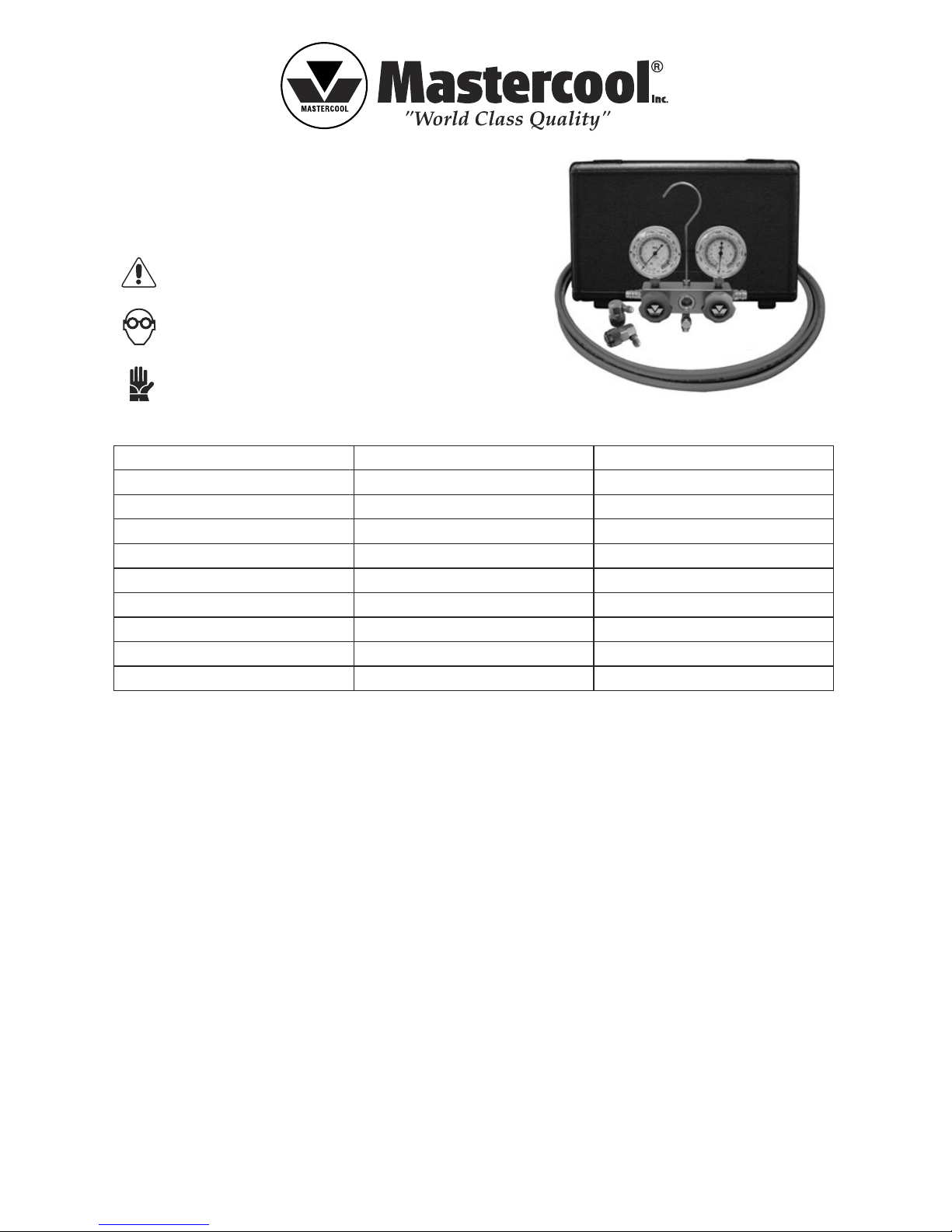
OPERATING INSTRUCTIONS
PROFESSIONAL R134a MANIFOLD GAUGE SET
PART #89660
WARNING
Wear Safety Goggles
Avoid Contact with Refrigerant
R134a TEMPERATURE PRESSURE CHART
Ambient Temp (˚F) Low Side Gauge High Side Gauge
65˚ 25-35 psi 135-155 psi
70˚ 35-40 psi 145-160 psi
75˚ 35-45 psi 150-170 psi
80˚ 40-50 psi 175-210 psi
85˚ 45-55 psi 225-250 psi
90˚ 45-55 psi 250-270 psi
95˚ 50-55 psi 275-300 psi
100˚ 50-55 psi 315-325 psi
105˚ 50-55 psi 340-345 psi
TROUBLESHOOTING TIPS
• Low side and high side pressure are low.
Usually indicates a low charge.
• Low side pressure is low and high side pressure is high.
Usually indicates a blockage in the system. (i.e. expansion of valve or orifice tube.)
• Low side pressure is high and high side pressure is low.
When accompanied by a vibrating gauge needle, usually indicates faulty reed valves in compressor.
• Low side and high side pressures are high.
Usually indicates an over charged system.
HOOK-UP FOR SYSTEM DIAGNOSIS:
• Verify that service ports are clean and free of metal shavings.
• Verify that both valves on the manifold are shut completely.
• Connect blue adapter to low side service port (5).
• Connect red adapter to high side service port (4).
• Start engine. Turn A/C mode selector to HIGH and fan to HIGH.
• Observe pressure on the manifold gauges and refer to your automotive manual for proper diagnosis.
CHARGING REFRIGERANT:
a. Verify that both valves on the manifold are shut completely.
Page 2
ww w.m as te rc oo l. co m
b. Turn on car and A/C system, (this will aid in charging of the refrigerant.)
c. Connect the other end of the yellow hose (3) to Refrigerant Gas supply. (Follow refrigerant manufacturer’s
instructions for proper dispensing.)
d. Open manifold low side (blue) valve slowly until pressure reaches 40 psi. Do not exceed 40 psi during the
recharging process. Exceeding 40 psi could damage the compressor.
e. When charging is finished, close low side (blue) valve.
EVACUATION OF SYSTEM WITH VACUUM PUMP AND LEAK TESTING:
a. Verify that there is no refrigerant in the A/C system.
b. Attached blue and red adapter to A/C system.
c. Connect yellow hose to vacuum pump, turn on pump.
d. Open manifold low side (blue) valve.
e. Open manifold high side (red) valve.
*After system had been evacuated to a gauge reading of 29” Hg (inches of vacuum), run vacuum pump for
20 minutes.
f. Close both high and low side manifold valves.
g. Allow system to sit and check gauges to verify vacuum remains.
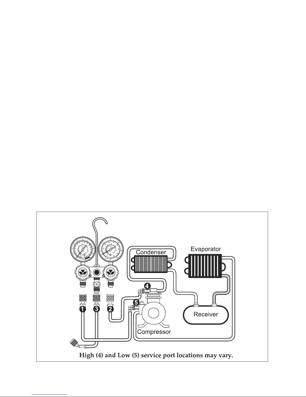
SYSTEM SCHEMATIC:
1. Low side (blue) hose/adapter.
2. High side (red) hose/adapter.
3. Service (yellow) hose.
4. Compressor discharge service valve (16mm diameter.)
5. Compressor suction service valve (13mm diameter.)
89660-INST
 Loading...