

Page 1
A/C SYSTEM ANALYZER MANUAL
1
12
11
2
3
4
10
9
5
6
8
7
Type K
Thermocouple
Antenna Fan Meter
Round Vane
Meter
Pressure
Transducer
Assembly
with Cable
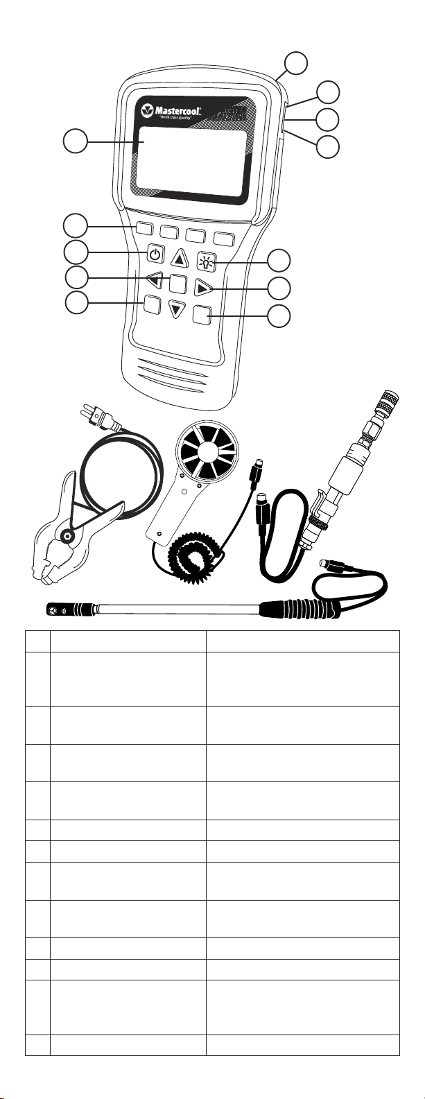
DESCRIPTION USE
1 Round Vane Meter/
Antenna Fan Meter
Socket
2 Pressure Transducer
Socket
Insert round vane meter or
antenna fan meter into socket
to use
Insert pressure transducer
cable into socket to use
3 USB Port Insert USB cable to upload
stored information
4 Type K Thermocouple
Socket
Insert thermocouple into
socket to use
5 Back Light Button Toggles back light on and off
6 Arrow Buttons Navigates screen
7 Calibration Button Use to calibrate pressure
transducer and thermocouple
8 Units Button Toggles between Imperial and
Metric units
9 Enter Button Selects highlighted value
10 Power Button Toggles power on and off
11 Function Buttons Selects operation on screen
directly above key
(F1, F2, F3, F4)
12 Screen Displays information
1ww w.m as te rc oo l. co m
Page 2

FIRST TIME USE
Set the Time
• Use POWER button to turn on A/C Analyzer.
• Use the ▼ or ▲ buttons to highlight the time.
• Press ENTER.
• Use the ◄ or ► buttons to highlight the hours, minutes,
and AM/PM or 24 hours.
• Use the ▲ or ▼ buttons to change the values.
NOTE: to change to AM or PM, add or subtract 12 hours.
• When correct, press F1 to SAVE.
NOTE: Press F4 to EXIT without saving.
Set the Date
• Use POWER button to turn on A/C Analyzer.
• Use ▼ or ▲ buttons to highlight the date.
• Press ENTER.
• Use the ◄ or ► buttons to highlight the Day, Month, Year
and Format.
• Use the ▲ or ▼ buttons to change the values.
NOTE: The format can be MM/DD/YYYY or DD/MM/YYYY.
• When correct press F1 to SAVE.
NOTE: Press F4 to EXIT without saving.
Set the Units
• Press the UNITS button at any time to toggle between
Imperial and Metric units.
QUICK START
General Functions
(in most screens:)
• Press F3 (T/S) to go to the Test Selection screen.
• Press F4 (EXIT) to go to the Main Menu screen.
Testing using Quick Start
Quick Start allows you to use the A/C System Analyzer
without entering a customer or technician.
NOTE: Testing done in Quick Start mode will only be saved
until the test is redone.
• Use power button to turn on A/C analyzer.
• Use the ▲ or ▼ buttons to highlight Quick Start.
• Press ENTER.
• Use ▼ or ▲ buttons to highlight the desired test.
• Press ENTER.
DB (DRY BULB)/WB (WET BULB)/RH
(RELATIVE HUMIDITY)/DP (DEW POINT)/ AIR
VEL (AIR VELOCITY) WITH AIR VOLUME
OPTION TESTING
• For round vane meter, twist sensor cover to the Open
position. For antenna fan meter, go to next step.
• Insert cable into socket (it may take a few seconds for
readings to appear).
• Place round vane meter or antenna fan meter
perpendicular to airflow.
AIR VOLUME TESTING
• When in DB/WB/RH/DP/Air Vel testing screen Press
ENTER.
• Use F2 (RECT/DIA) to toggle between rectangular and
round duct.
2 ww w.m as te rc oo l. co m
Page 3

• Use ► or ◄ buttons to highlight digit and ▲ or ▼ buttons
to change digit value.
• Press ENTER to toggle between Height and Width.
NOTE: Be sure to press ENTER for both Height and Width
before pressing done.
• Press F1 when DONE entering duct size.
• Place round vane meter or antenna fan meter
perpendicular to air flow to read volume.
TARGET SUPERHEAT TESTING
• Target Superheat Testing uses the round vane meter or
antenna fan meter. For round vane meter, twist sensor
cover to the Open position. For antenna fan meter, go to
next step.
• Insert cable into socket (it may take a few seconds for
readings to appear).
• Follow Target Superheat 1 screen instructions on where to
place round vane meter or antenna fan meter.
• When values have stabilized, press ENTER to save.
• Press F2 (NEXT).
• Follow Target Superheat 2 screen instructions on where to
place round vane meter or antenna fan meter.
• When values have stabilized, press ENTER to save.
• Press F2 (NEXT).
• Target Superheat will be displayed on the screen.
• If Actual Superheat has been tested, Press F1 (ANYL) for
analysis.
TEMPERATURE SPLIT TESTING
• Temperature (TEMP) Split Testing uses the round vane
meter or antenna fan meter. For round vane meter, twist
sensor cover to the Open position. For antenna fan meter,
go to next step.
• Insert cable into socket (it may take a few seconds for
readings to appear).
• Follow Temp Split 1 screen instructions on where to place
round vane meter or antenna fan meter.
• When values have stabilized, press ENTER to save.
• Press F2 (NEXT).
• Follow Temp Split 2 screen instructions on where to place
round vane meter or antenna fan meter.
• When values have stabilized, press ENTER to save.
• Press F2 (ANYL).
• Target Temperature Split and Actual Temperature Split with
analysis will be displayed on the screen.
ACTUAL SUPERHEAT TESTING
• Use ▲ or ▼ buttons to highlight Actual Superheat.
• Press ENTER.
To Input Pressure Manually
• Use ▲ or ▼ buttons and highlight Input Manually.
• Press ENTER.
• Use ▲ or ▼ buttons to highlight refrigerant.
• Press ENTER.
• Use ► and ◄, buttons to highlight unit and ▲ and ▼
buttons to adjust unit value to input low-side saturated
pressure.
• Press ENTER.
• Saturated vapor temperature will be displayed.
3ww w.m as te rc oo l. co m
Page 4

• Press F2 (NEXT).
• Insert plug for clamp-on thermocouple into type K
thermocouple socket.
• Follow screen instructions to place clamp-on thermocouple.
• When temperature has stabilized, press ENTER.
• Press F2 (NEXT).
• Actual Superheat will be displayed.
• If Target Superheat test has been done, press F1 (ANLY)
for analysis.
To use Pressure Transducer to Calculate Superheat
• Use ▲ or ▼ buttons to highlight Calculate.
• Press ENTER.
• Use ▲ or ▼ buttons to select refrigerant.
• Press ENTER.
• Insert plug from pressure transducer into pressure
transducer socket.
• Follow screen instructions to connect pressure transducer
to system.
• When saturated temperature stabilizes, press F2 (NEXT).
• Insert plug from clamp-on thermocouple into type K
thermocouple socket.
• Follow screen instructions to place clamp-on thermocouple.
• When temperature has stabilized, press ENTER.
• Press F2 (NEXT).
• Actual Superheat will be displayed.
• If Target Superheat test has been done, press F1 (ANLY)
for analysis.
ACTUAL SUBCOOL TESTING
• Use ▲ or ▼ buttons to highlight Actual Subcool.
• Press ENTER.
To Input Pressure Manually
• Use ▲ or ▼ buttons and highlight Input Manually.
• Press ENTER.
• Use ▲ or ▼ Buttons to select refrigerant.
• Press ENTER.
• Use ► and ◄, buttons to highlight unit and ▲ and ▼
buttons to adjust unit value to input high-side saturated
pressure.
• Press ENTER.
• Saturated vapor temperature will be displayed.
• Press F2 (NEXT).
• Insert plug for clamp-on thermocouple into type K
thermocouple socket.
• Follow screen instructions to place clamp-on thermocouple.
• When temperature has stabilized, press ENTER.
• Press F2 (NEXT).
• Actual Subcool will be displayed.
To use Pressure Transducer to Calculate Subcool
• Use ▲ or ▼ button to highlight Calculate.
• Press ENTER.
• Use ▲ or ▼ button to select refrigerant.
• Press ENTER.
• Insert plug from pressure transducer into pressure
transducer socket.
• Follow screen instructions to connect pressure transducer
4 ww w.m as te rc oo l. co m
Page 5

to system.
• When saturated temperature stabilizes, press ENTER.
• Press F2 (NEXT).
• Insert plug from clamp-on thermocouple into type K
thermocouple socket.
• Follow screen instructions to place clamp-on thermocouple.
• When temperature has stabilized, press ENTER.
• Press F2 (NEXT).
• Actual Subcool will be displayed.
SAVING TEST INFORMATION (NEW ENTRY)
• Use NEW ENTRY to save testing information under
Customer, Technician, and Date.
To enter a New Customer
• Use power button to turn on A/C Analyzer.
• Use ▲ or ▼ buttons to highlight NEW ENTRY.
• Press ENTER.
• New Customer will be highlighted.
• Press ENTER.
• Use ▲ or ▼ buttons to adjust letter or number.
NOTE: Using ▼ button will go directly to numbers.
• Use ► or ◄ buttons to highlight next space.
• When done press ENTER.
• Use ▲, ▼, ►, or ◄ buttons to enter Technician.
• When done press ENTER.
• Press F1 (DONE).
• NEW TEST will be highlighted.
• Press ENTER.
• Any testing will be recorded under the current date. For
instructions on how to do the testing see Quick Start.
• To see the testing summary press F2 (DATA) at the end of
each test except DB/WB/RH/DP/Air Vel.
To add a test to an Existing Customer
• Use POWER button to turn on A/C Analyzer.
• Use ▲ or ▼ buttons to highlight NEW ENTRY.
• Use ▼ or ▲ buttons to highlight existing Customer.
• Press ENTER.
• NEW TEST will be highlighted.
• Press ENTER.
• Any testing will be recorded under the current date and
time. For instructions on how to do the testing see Quick
Start.
• To see the testing summary press F2 (DATA) at the end of
each test except DB/WB/RH/DP/Air Vel.
LOOKING AT PREVIOUSLY SAVED
INFORMATION
• Use POWER button to turn on A/C Analyzer.
• Use ▲ or ▼ buttons to highlight Customer Search.
• Press ENTER.
• Use ▲ or ▼ buttons to highlight Customer.
• Press ENTER.
• Use ▲ or ▼ buttons to highlight Test Number.
• Press ENTER.
• Saved test data will be displayed.
5ww w.m as te rc oo l. co m
Page 6

NOTE: The Customer or Test can be deleted by pressing F2
(DEL) when they are highlighted.
CALIBRATION
• Use POWER button to turn on A/C Analyzer.
• From MAIN MENU press CAL button.
For Thermocouple Calibration
NOTE: Press F4 (EXIT) in Thermocouple Cal 1 Screen to
return to MAIN MENU without saving, or F2 (PT) to calibrate
the pressure transducer.
• Insert thermocouple into thermocouple socket.
• Place thermocouple at known temperature and allow
temperature to stabilize.
NOTE: Use crushed ice and just enough water to cover and
calibrate to 32˚F or 0˚C, or place thermocouple clamp on a
heavy wall copper pipe and clamp a calibrated meter next to
it.
• Use ► and ◄, buttons to highlight unit and ▲ and ▼
buttons to adjust unit value to input calibration temperature.
• Press F1 (CAL) button.
• If thermocouple has correct reading, press F4 (EXIT) to
save.
• If thermocouple reading is off, Press F1 (REDO) to redo the
calibration.
For Pressure Transducer Calibration
CAUTION: To calibrate the pressure transducer you will
need a source of high-pressure gas with a highly accurate
calibrated gauge. Do not start calibrating the pressure
transducer without it. For best results, calibrate sensor at
close to its maximum value.
NOTE: Press F4 (EXIT) in Pressure Transducer 1 and
Pressure Transducer 2 Screens to return to MAIN MENU
without saving, or F2 (TC) to calibrate the thermocouple.
• If in Thermocouple 1 screen, Press F2 (PT) button to
display Pressure Transducer 1 screen.
• Two pressures are required, one low and one high.
Atmospheric (0) is OK for the low pressure.
• With the pressure transducer at low pressure, use ► or ◄,
buttons to highlight unit and ▲ or ▼ buttons to adjust unit
value to input the low pressure.
• Press F1 (NEXT).
• With the pressure transducer at the high pressure, use ►
or ◄, buttons to highlight unit and ▲ or ▼ buttons to adjust
unit value to input the high pressure.
• Press F1 (CAL).
• If pressure transducer reading is correct, Press F4 (EXIT)
to save and return to MAIN MENU.
• If pressure transducer reading is off, press F1 (REDO) to
redo the high pressure setting.
SPECIFICATIONS:
System Analyzer
• Operating Temperature: 0 to 50˚C (32 to 122˚F), humidity <80%
• Storage Temperature: -20 to 50˚C (-4 to 122˚F), humidity <90%
• Dimensions with boot: 191mm x 93mm x 41mm
• Weight: (meter w/ batteries & round vane) 500g
• Temperature Display: ˚F and ˚C
• Pressure Display: PSI and Bar
• Backlit LCD Display
• Low battery indicator
• K-type thermocouple connection
6 ww w.m as te rc oo l. co m
Page 7

• USB connection
• 6 AA batteries
Round Vane
Temp. Range/Resolution/Accuracy:
• -20 to 60˚C (-4 to 140˚F)
• 0.1˚C (0.2˚F)
• ±0.6˚C (1.1˚F) (-20 to 50˚C (-4 to 122˚F)),
±1.2˚C (2.2˚F) at other range
Humidity Range/Resolution/Accuracy:
• 0.1% to 99.9% RH
• 0.1% RH
• ±3% RH (at 25˚C (77˚F), 10 to 90% RH), ±5% RH at other range
Windspeed Range/Resolution/Accuracy:
• 0.6 to 32 m/s
• 0.1 m/s
• ±2% of full scale
Antenna Type Meter
Temp. Range/Resolution/Accuracy:
• -20 to 60˚C (-4 to 140˚F)
• 0.1˚C (0.2˚F)
• ±0.6˚C (1.1˚F) (-20 to 50˚C (-4 to 122˚F)),
±1.2˚C (2.2˚F) at other range
Humidity Range/Resolution/Accuracy:
• 0.1% to 99.9% RH
• 0.1% RH
• ±3% RH (at 25˚C (77˚F), 10 to 90% RH), ±5% RH at other range
Windspeed Range/Resolution/Accuracy:
• 0.5 to 25 m/s
• 0.1 m/s
• ±(2% of reading +0.3 m/s)
Pressure Transducer
• Operating Pressure Range: 0-750 psi (0-52 bar)
• 1/4FL Swivel nut connection
• Accuracy: ±0.5, ±1% F.S.
• Operating Temperature: -40 to 100˚C (-40 to 212˚F)
Clamp-on Thermocouple
Temp. Range/Resolution
• -40 to 121˚C (-40 to 250˚F)
• 0.1˚C (0.2˚F)
7ww w.m as te rc oo l. co m
Page 8

USA: PH (973) 252-9119
BELGIUM: TEL. + 32 (0) 3 777 28 48
8 ww w.m as te rc oo l. co m
 Loading...