

Page 1
English
Deutsch
Français
Español
Portuguese
OPERATING INSTRUCTIONS
DIGITAL CLAMP METER MODEL#–52240
BEDIENUNGSANLEITUNG
DIGITALES ZANGENMESSGERÄT MODEL#–52240
MANUEL D’OPÉRATION
PINCE MULTIMETRE NUMERIQUE MODÈLE#–52240
INSTRUCCIONES DE OPERACION
MEDIDOR DIGITAL CON ABRAZADERA MODELO#–52240
MANUAL DE OPERAÇÃO
ALICATE AMPERÍMETRO DIGITAL MODELO#–52240
1www.mastercool.com
Page 2
P H
PEAK
HOLD
DATA
HOLD
600 OFF
200
200
20K 2K
750
200
1000
20
Hz
DIGITAL CLAMP METER
A
V
V
MAX 1000V 750V ~ 600A ~
52240
INPUT
WAVEFORM
PK-PK O-PK RMS AVG
2.828 1.414 1.000 0.900
1.414 1.414 1.000 0.900
2.828 2.828 1.414 0.900
1.800 0.900 0.900 0.900
1.800 1.800 1.272 0.900
0.9/D 0.9/D 0.9/D 0.9/D
3.600 1.800 1.038 0.900
Display Multiplier for
Measurement Conversion
PEAK
PEAK
PEAK
PEAK
PK
0
PK
0
PEAK
PK
0
SINE
RECTIFIED SINE
(FULL WAVE)
RECTIFIED SINE
(HALF WAVE)
SQUARE
RECTIFIED SQUARE
RECTANGULAR PULSE
TRIANGLE SAWTOOTH
PK
0
PK
0
PEAK
PK
0
PEAK
PK
0
X
Y
D=X/Y
P H
PEAK
HOLD
DATA
HOLD
600 OFF
200
200
20K 2K
750
200
20
Hz
A
52240
English
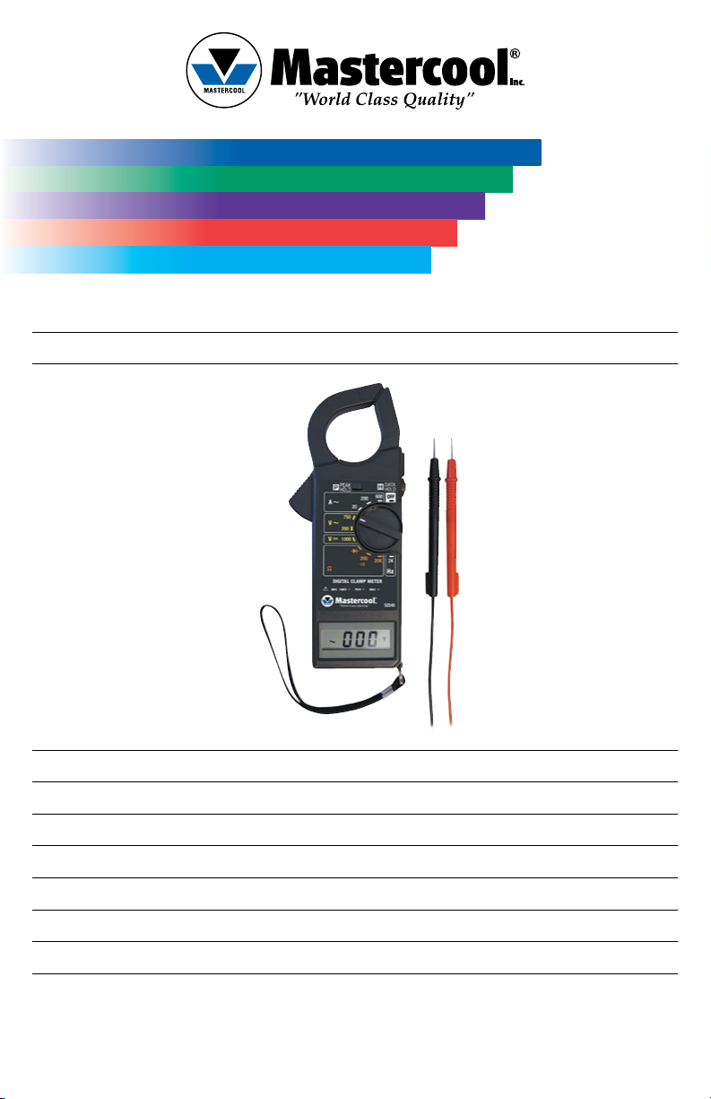
52240 Digital Clamp Meter
Instruction Manual
This clamp meter is completely portable, 3 1/2 digit hand held test instrument provides versatile measuring capabilities. It
is an ideal tester for maintenance and inspection on all types of electrical equipment.
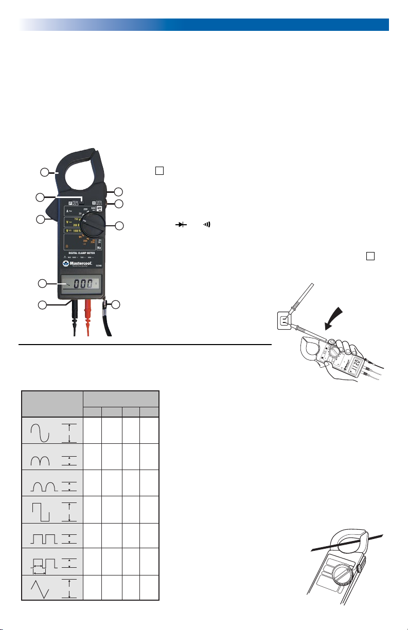
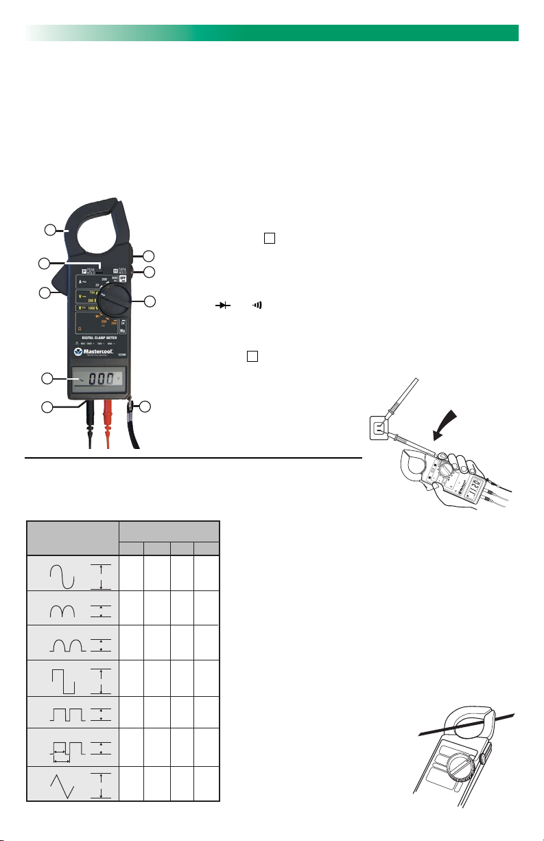
FEATURES
• Multi-Function: Frequency Count, Diode Check and Alarm • AC voltage: 200V / 750V
• DC voltage: 1000V • Peak Data Hold
• Frequency: 2KHz • Unit and Sign Display
• Resistance (ohm): 200 ohm / 20k ohm • AC current: 20A / 200A / 600A
1. Transformer Jaws: Measures the AC current flowing through the conductor.
2. PEAK HOLD Switch: A push switch (push ON, OFF, ON: LCD displays
(
sign). Peak detector holds the maximum RMS value of Current or
1
P
Voltage surge while a motor is starting.
6
2
3
3. Trigger: Press the lever to open the transformer jaws. When the pressure
lever is released, the jaws will close again.
7
4. Display: 3 1/2 digit (1999 count), unit and sign display.
5. V, Hz, “
8
” , “ ”. Input Connector: High (+) and Low (-) input jack for
all voltage, resistance, frequency, continuity, and diode measurement.
6. Slot to Clamp in the Probe: Clamp the test probe for measurement.
7. DATA HOLD Switch: A push switch, (Push ON, OFF, ON: LCD displays (
H
sign). Holds the reading on the LCD display (for all functions and ranges.)
4
5
8. Rotary Switch: A rotary switch is used to select measurement function,
Range, and Power (ON/OFF) switch.
9. Drop-Preventing Wrist Strap:
9
Prevents the instrument from
slipping off the
hand while in use.
DATA
HOLD
600 OFF
200
APPLICATIONS
Probe may be snapped into “Slot” so only one hand is needed to hold
both the Meter and probe tip in contact with test point.
FIGURE 1
INPUT
WAVEFORM
SINE
PK
0
2.828 1.414 1.000 0.900
RECTIFIED SINE
(FULL WAVE)
PK
1.414 1.414 1.000 0.900
0
RECTIFIED SINE
(HALF WAVE)
PK
2.828 2.828 1.414 0.900
0
SQUARE
PK
1.800 0.900 0.900 0.900
0
RECTIFIED SQUARE
PK
1.800 1.800 1.272 0.900
0
RECTANGULAR PULSE
PK
0.9/D 0.9/D 0.9/D 0.9/D
0
TRIANGLE SAWTOOTH
PK
0
3.600 1.800 1.038 0.900
PEAK
PEAK
PEAK
PEAK
PEAK
D=X/Y
PEAK
X
Y
PEAK
Display Multiplier for
Measurement Conversion
PK-PK O-PK RMS AVG
2 www.mastercool.com
OPERATING INSTRUCTIONS
This section of the manual will provide you with information on
measurement techniques to help you fully utilize the measurement
capabilities of this instrument.
AC Current Measurement
This Clamp Meter measures the average value of an AC signal and
displays it as an equivalent RMS value for a sine wave. The measurements errors are introduced when the input wave form is distorted
(non-sinusoidal). The amount of errors depends upon the amount of
distortion. (FIGURE 1) shows the relationship between sine, square,
triangular waveforms and the required conversion factors.
1. Set Function/Range switch to desired A~range. (20Ã or 200 Ã
or 600 Ã)
2. Press the trigger to open the transformer
jaw and clamp one conductor to be
measured. (FIGURE 2).
3. Read the AC current value on LCD.
4. If you want to hold the display value,
push the DATA HOLD switch before
removing the transformer jaws from
the conductor.
Hz
20
20K 2K
PEAK
HOLD
52240
750
P H
200
200
A
1000
V
V
DIGITAL CLAMP METER
MAX 1000V 750V ~ 600A ~
FIGURE 2
Page 3

AC/DC Voltage Measurement
1. Set Function/Range Switch to desired V~ or V “ ” range.
2. Insert the red test probe to “ + ” input jack and black test probe to “ - ” input jack.
3. Connect test prods of test probes IN PARALLEL to the circuit being measured.
4. Read the voltage value on LCD.
5. If you want to hold the display value, push the DATA HOLD switch before disconnecting the probes from the measuring
points.
Resistance Measurement
1. Set Function/Range Switch to desired range.
2. Insert the red/black test probes to the “ + ” and “ - ” input jacks respectively.
3. Connect the test probes to the circuit being measured and read the resistance value on LCD.
WARNING: Before taking any in-circuit resistance measurement, remove power from the
circuit being tested and discharge all capacitors.
Diode Tests (“ ”)
1. Set Function/Range Switch to “ ” range.
2. Insert the red test probe to “ + ” input jack and black test probe to “ - ” input jack.
3. Connect the Red test probe to the anode side and Black test probe to the cathode side of the diode being tested.
4. Read forward voltage (Vf) Value on LCD.
5. Connect the test probe to the diode, opposite of step 3. The digital display value should be over range (1). This can be
used for distinguishing anode and cathode poles of a diode.
WARNING: Before taking any in-circuit measurement remove power from the circuit being tested
and discharge all capacitors in the circuit.
Continuity Measurements “ ”
1. Set Function/Range Switch to “ ” position.
2. Insert the red/black test probes to the “+” and “-” input jacks.
3. Connect the test probes to the circuit being measured.
4. When the impedance on circuit is below 100, a continuous beep will sound.
Frequency Measurement (Hz)
1. Set Function/Range Switch to 2 KHz Range.
2. Insert the red/black test probes to the “+” and “-” input jacks.
3. Connect the test probes to the circuit being measured.
4. Read the frequency value (Hz) on LCD.
PEAK DETECT MEASUREMENT
1. Set Function/Range Switch to desired A ~ or V ~ range.
2. Set the Clamp Meter into the “PEAK HOLD” mode by pushing the “PEAK HOLD” Switch. The LCD display will indicate
“P” when Peak Detect mode is measured.
3. Follow this procedure for AC voltage and Current measurement. The displayed reading is the maximum RMS value of a
surge in current or a Voltage pulse. The reading decays at the rate of about 1 digi/second.
GENERAL SPECIFICATIONS
Display:
3 1/2 digit LCD (1999 count) with “ P ” (Peak Hold), “ H ” (Data Hold), “-”,
“BT” (Lo Bat), “~”, “V”, “A”, “ ”, “K”, “KHz” and decimal enunciators.
Sampling Rate:
Diameter of Conductor:
Polarity:
Range Selection:
Over Range Indication:
Low Battery Indication:
Battery Life:
Power Requirements:
Operating Temperature and Humidity:
Storage Temperature and Humidity:
Dimension:
Weight:
Accessories:
2.5 times per second.
40mm max.
Automatic “-” negative polarity indication.
All ranges are measured by single range switch operation.
Highest digit of (1) or (-1) is display.
“BT” appears on display in the last 20% of battery life.
Up to 200 hours with an Alkaline battery.
Single 9V battery.
32ºF to 104ºF (0ºC to 40ºC) below 80%RH
14ºF to 140ºF (-10ºC to 60ºC) below 80%RH.
8.2”L x 2.6”W x 1.3”H (208 x 65 x 31mm).
1.6 oz (330g) including battery.
Test probes, Instruction Manual, Carrying Case, Battery
3www.mastercool.com
Page 4
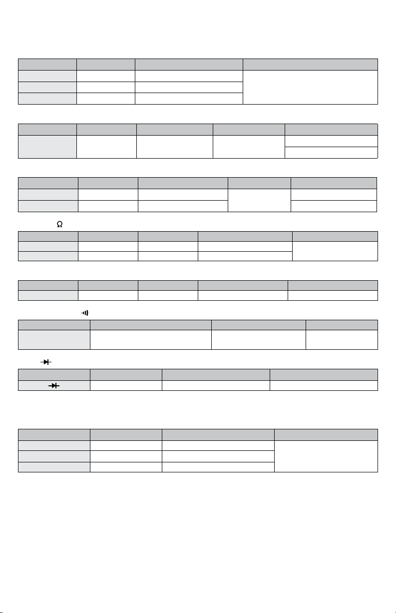
ELECTRICAL SPECIFICATIONS
Accuracies are ± (% reading + tolerance) at 23ºC ± 5ºC below 80%RH.
1. General Measurement
AC Current
Range Resolution Accuracy (50Hz/60-Hz) Overload
20A 10mA ± (2% rdg + .05A)
Protection 1000A (within 60 sec.)200A 100mA ± (2% rdg + .5A)
600A 1A ± (2% rdg + 5A)
DC Voltage
Range Resolution Accuracy Input Impedance Overload Protection
1000V 1V ± (0.8% rdg + 2 volts) 10M
AC Voltage
Range Resolution Accuracy (40Hz~400Hz) Input Impedance Overload Protection
200V 100mV ± (1.2% rdg + .3V)
750V 1V ± (1.2% rdg + 3V) AC800V
10M
DC1100V
AC800V
DC1100V
Resistance (
)
Range Resolution Accuracy Max. Open Circuit Voltage Overload Protection
200 100m ± (1% rdg + .2) 3.5V
20K 10 ± (1% rdg + 20) 0.3V
350Vrms
Frequency (Hz) (10Hz ~ 2KHz)
Range Resolution Accuracy Max. Input Sensitivity
Max. Allowable Applied Voltage
2KHz 1Hz ± (1% rdg + 2Hz) 100mV 350Vrms
Continuity Check (
)
Range Description Max. Open Circuit Voltage Overload Protection
Built-in buzzer sounds if conductance
is less than 100
3.5V 350Vrms
Diode (
20A
)
Range Resolution Max. Open Circuit Voltage Overload Protection
1mV 3.5V 350Vrms
2. Peak Hold Measurement
(Capture and retain momentary voltage or current surge and display it.)
AC Current
Range Resolution Accuracy (40Hz~400Hz) Overload Protection
20A 10mA ± (2% rdg + .1A)
1000A (within 60 sec.)200A 100mA ± (2% rdg + 1A)
600A 1A ± (2% rdg + 10A)
Peak Detect Acquisitions Time: Approx. 100ms.
(Acquisition time is the minimum duration of a surge for rated accuracy. Accuracy improves for longer peak duration).
SAFETY RULES
1. Never ground yourself when taking electrical measurements. Keep your body isolated from ground by using dry
clothing, rubber shoes, rubber mats or any suitable and approved insulating material.
2. Disconnect input signal before touching the battery.
4 www.mastercool.com
Page 5
P H
PEAK
HOLD
DATA
HOLD
600 OFF
200
200
20K 2K
750
200
1000
20
Hz
DIGITAL CLAMP METER
A
V
V
MAX 1000V 750V ~ 600A ~
52240
INPUT
WAVEFORM
PK-PK O-PK RMS AVG
2.828 1.414 1.000 0.900
1.414 1.414 1.000 0.900
2.828 2.828 1.414 0.900
1.800 0.900 0.900 0.900
1.800 1.800 1.272 0.900
0.9/D 0.9/D 0.9/D 0.9/D
3.600 1.800 1.038 0.900
Display Multiplier for
Measurement Conversion
PEAK
PEAK
PEAK
PEAK
PK
0
PK
0
PEAK
PK
0
SINE
RECTIFIED SINE
(FULL WAVE)
RECTIFIED SINE
(HALF WAVE)
SQUARE
RECTIFIED SQUARE
RECTANGULAR PULSE
TRIANGLE SAWTOOTH
PK
0
PK
0
PEAK
PK
0
PEAK
PK
0
X
Y
D=X/Y
9
8
7
6
5
4
3
2
1
P H
PEAK
HOLD
DATA
HOLD
600 OFF
200
750
200
20
A
V
INPUT
WAVEFORM
PK-PK O-PK RMS AVG
2.828 1.414 1.000 0.900
1.414 1.414 1.000 0.900
2.828 2.828 1.414 0.900
1.800 0.900 0.900 0.900
1.800 1.800 1.272 0.900
0.9/D 0.9/D 0.9/D 0.9/D
3.600 1.800 1.038 0.900
Display Multiplier for
Measurement Conversion
PEAK
PEAK
PEAK
PEAK
PK
0
PK
0
PEAK
PK
0
SINE
RECTIFIED SINE
(FULL WAVE)
RECTIFIED SINE
(HALF WAVE)
SQUARE
RECTIFIED SQUARE
RECTANGULAR PULSE
TRIANGLE SAWTOOTH
PK
0
PK
0
PEAK
PK
0
PEAK
PK
0
X
Y
D=X/Y
Signal d'entrée
de form d'onde
PK-PK O-PK RMS AVG
2.828 1.414 1.000 0.900
1.414 1.414 1.000 0.900
2.828 2.828 1.414 0.900
1.800 0.900 0.900 0.900
1.800 1.800 1.272 0.900
0.9/D 0.9/D 0.9/D 0.9/D
3.600 1.800 1.038 0.900
Multiplicateur applicable pour
conversion de mesure
PEAK
PEAK
PEAK
PEAK
PK
0
PK
0
PEAK
PK
0
SINE
RECTIFIED SINE
(FULL WAVE)
RECTIFIED SINE
(HALF WAVE)
SQUARE
RECTIFIED SQUARE
RECTANGULAR PULSE
TRIANGLE SAWTOOTH
PK
0
PK
0
PEAK
PK
0
PEAK
PK
0
X
Y
D=X/Y
Entrada para
Forma de Onda
PK-PK O-PK RMS AVG
2.828 1.414 1.000 0.900
1.414 1.414 1.000 0.900
2.828 2.828 1.414 0.900
1.800 0.900 0.900 0.900
1.800 1.800 1.272 0.900
0.9/D 0.9/D 0.9/D 0.9/D
3.600 1.800 1.038 0.900
Exhibe Multiplicador la
conversiòn de la medida
PICO
PICO
PICO
PICO
PK
0
PK
0
PICO
PK
0
SENO
SENO RECTIFICADO
(ONDA COMPLETA)
SENO RECTIFICADO
(MEDIA ONDA)
CUADRADO
CUADRADO RECTIFICADO
PULSO RECTANGULAR
TRIANGULO DIENTE DE SIERRA
PK
0
PK
0
PICO
PK
0
PICO
PK
0
X
Y
D=X/Y
Deutsch
52240 Digitales Zangenmessgerät
Betriebsanweisung
Dieses Zangenmessgerät ist ein tragbares Prüfgerät mit 14 mm grosser Datenanzeige und es erlaubt sämtliche Messungen verschiedener Art. Es ist ein ideales Messgerät bei Wartung und Pflegearbeiten an elektrischen Anlagen und Geräten.
MERKMALE
• Wechselstrom : 10mA bis 600A • Gleichstromspannung : 1V bis 1000 V
• Durchgangsstörungsmeldung (Akustisch) • Messwerte & Spitzenwertespeicher
• Wechselspannung : 100 mV bis 750 V • Frequenzmessung : 10Hz bis 2 K Hz
• Diodenprüfung • Einheit & Symbolzeichen
1. Klemm und Führungsbacken: Zum Messen von Wechselstromspannung in
Stromleitungen.
1
2
3
4
5
2. Schalter für Spitzenwerte (Peak hold): Ein Druckschalter (beim drücken ON,
OFF, ON : LCD zeigt
Strom oder Spannungswelle während einen Motor angelassen wird.
6
3. Kippschalter: Dieser Hebel drücken zum Öffnen der Klemmbacken. Bei Drucka
7
bnahme schliessen sich die Klemmbacken wieder.
4. Display: 14 mm grosse Zahlen (bis1999), Einheit und Zeichenandeutung.
8
5. V, Hz, “
für alle Spannung-, Widerstand-, Frequenz-, Kontinuität- und Diodenmessungen.
6. Schlitz zur Befestigung der Probe: Probe befestigen während Messungen.
7. Schalter zum Wertspeicher (Data hold): Ein Drückschalter (beim drücken ON, OFF,
ON : LCD zeigt
Funktionen und Werte).
8. Funktionsschalter, drehbar: Dieser drehbare
Schalter wählt die Messfunktionen, Bereich und
9
Ein/Ausschalt (On/Off).
9. Trageband für das Handgelenk: Zum
vermeiden dass das Gerät wegrutscht
oder herunterfällt.
ANWENDUNGEN
Die Probe kann im Schlitz befestig werden,damit man gleichzeitig mit einem Hand das
Messgerät und den Probenspitz in Kontakt bringt mit der Prüfstelle.
ABBILDUNG 1
Eingangs –
Wellenform
Sinus Spitzenwert
PK
0
2.828 1.414 1.000 0.900
Angepasster Sinus (Volle Welle)
PK
1.414 1.414 1.000 0.900
0
Angepaster Sinus (Halbe Welle)
PK
2.828 2.828 1.414 0.900
0
Rechteckig Spitzenwert
PK
1.800 0.900 0.900 0.900
0
Rechteckig Spitzenwert Angepasst
PK
1.800 1.800 1.272 0.900
0
Rechteckiger Spitzenwert Pulsation
D=X/Y
PK
X
0.9/D 0.9/D 0.9/D 0.9/D
0
Y
Dreieckiger Spitzenwert Sägezahn
PK
3.600 1.800 1.038 0.900
0
Display Multiplikator für
Mess-Umrechnungen
PK-PK O-PK RMS AVG
PEAK
PEAK
PEAK
PEAK
PEAK
PEAK
PEAK
” , “ ”. Steckereingang: Hoch ( + ) und Niedrig ( - ) Steckerprobe
P
Zeichen) Spitzenwert von maximalem Drehzahlwert der
H
Zeichen). Speichert die Werte auf dem LCD – Display (Für alle
BEDIENUNGSANWEISUNGEN
In diesem Teil der Bedienungsanweisung finden Sie sämtliche Hinweise damit alle verschiedenen Messtechniken optimal benutzt werden.
Wechselstrommessungen
Dieses Zangenmessgerät misst den durchsch-nittlichen Wert eines
Wechselstromsignals undzeigt dieses als Äquivalenter RMS – Wert
einer Sinuswelle. Die Messfehler werden eingegebensobald die
Eingangswellenangabe sich verformthat. (Non – Sinusoidal). Die
Fehlerzahl ist jenachdem das Mass der Verformung. Abbildung 1.
zeigt das Verhältnis zwischenSinus, Quadrat, Dreieckwellenangaben
und den gewünschten Umrechnungsfaktoren.
1. Der Funktionsschalter positionieren auf den erwünschten
A-Bereich. (20A oder 200 A oder 600A).
2. Der Kippschalter drücken damit sich die
Klemmbacken öffnen und einen Stromführer
umfassen zum Messen. (Abbildung 2).
3. Der Wechselstromwert wird im Display
gezeigt.
4. Wollen Sie der Displaywert speichern, dann
drücken Sie der Data-Hold Schalter (7)
bevor die Klemmbacken vom Stromführer
wegzunehmen.
DATA
HOLD
600 OFF
200
Hz
20
20K 2K
PEAK
HOLD
52240
750
P H
200
200
A
1000
V
V
DIGITAL CLAMP METER
MAX 1000V 750V ~ 600A ~
ABBILDUNG 2
5www.mastercool.com
Page 6

Wechsel/Gleichspannung Messungen
1. Der Funktionsschalter positionieren auf den erwünschten V~ or V “ ” Bereich.
2. Die rote Testprobe anschliessen an den „+“ Anschluss und die schwarze Testprobe an den „-„ Anschluss.
3. Die Testproben in parallel mit dem gemessenen Stromkreis verbinden.
4. Der Spannungswert am Display auslesen.
5. Wenn Sie diesen Spannungswert speichern möchten, dann zuerst den Data Hold Schalter eindrücken bevor Sie die
Testproben von deren Messstellen wegnehmen.
Widerstandmessung
1. Der Funktionsschalter positionieren auf den erwünschten Bereich.
2. Die rote/schwarze Testprobe an der respektiven „+“ und „-„ Anschluss anschliessen.
3. Die Testproben mit dem gemessenen Stromkreis verbinden und den Widerstandswert am Display auslesen.
Warnung: Bevor man irgendwelche interne Widerstandsmessung ausführt, muss zuerst die Stromspannung im
gemessenen Kreis ausgeschaltet sein, und alle Kapazitoren müssen Spannungsfrei sein.
Dioden Prüfmessung (“ ”)
1. Der Funktionsschalter positionieren auf “ ” Bereich.
2. Die rote/schwarze Testprobe an der respektiven „+“ und „-„ Anschluss anschliessen.
3. Die rote Testprobe verbinden mit der Anodeseite und die schwarze Testprobe mit der Kathodenseite von der zu prüfen Diode.
4. Die Vorspannung (Vf) am Display auslesen.
5. Die Testproben weiter verbinden mit der Diode, jedoch in umgekehrtem Form wie bei 3; der im Display gezeigte Wert
wird jetzt ausserhalb dem in 1. angedeuteten Bereich liegen. Dieser Information kann gebraucht werden bei der
Beurteilung von Anode-Kathode Pole einer Diode.
Warnung: Bevor eine Messung auszuführen, muss zuerst die Stromspannung im gemessenen
Kreis ausgeschaltet sein, und alle Kapazitoren müssen Spannungsfrei sein.
Kontinuitätsmessung “ ”
1. Der Funktionsschalter positionieren auf “ ” position.
2. Die rote/schwarze Testproben an der „+“ und „-„ Anschluss anschliessen.
3. Die Testproben mit dem gemessenen Stromkreis verbinden.
4. Wenn die Impedanz im Stromkreis unter 100 liegt , wird einen Dauer Signal Ton hörbar.
Frequenzmessung (Hz)
1. Der Funktionsschalter positionieren auf dem 2 KHz Bereich.
2. Die rote/schwarze Testproben an der „+“ und „-„ Anschluss anschliessen.
3. Die Testproben mit dem gemessenen Stromkreis verbinden.
4. Der Frequenzwert (Hz) am Display auslesen.
SPITZENWERT
1. Der Funktionsschalter positionieren auf erwünschten A ~ oder V ~ Bereich.
2. Das Zangenmessgerät wird in der Spitzenwert Position gebracht durch den „Peak-Hold“ Schalter zu drücken. Das
Display wird das „ P “ zeigen sobald den Spitzenwert erreicht wird.
3. Dieser Prozedur verfolgen bei der Wechselspannung und Strommessung. Der gezeigte Displaywert ist der höchste RMS
Wert einer Stromstoss oder Spannungspulsation. Die Auslesung nimmt ab mit etwa 1 Digi pro Sekunde.
ALLGEMEINE SPEZIFIKATIONEN
Display:
14 mm grosse Zahlen (Bis 1999 Zahl) mit „ P “ (Spitzenwert), „ H “
(Speicherwert) „-„ , „BT“ (Batterieschwache), “~”, “V”, “A”, “ ”, “K”,
“KHz” und Dezimal Andeutung.
Wertzeichen:
Durchmesser vom Stromführer:
Polarität:
Bereiche Auswahl:
Andeutung für Ausserbereich:
Andeutung Für Batterieschwäche:
2.5 Mal pro Sekunde.
Bis 40 mm Maximum.
Automatischen „-„ Negativer Polarität Andeutung.
Alle Bereiche sind messbar durch einzelne Schalterbedienung.
Höchste Zahl (1) oder (-1) ist Display.
Das “BT” Zeichen erscheint im Display beim erreichen der letzte 20% vom
Batterie Standzeit.
Batterie Lebensdauer:
Antrieb:
Arbeitstemperatur und Feuchte:
Aufbewahrungstemperatur und Feuchte:
Abmessungen:
Gewicht:
Zubehör:
6 www.mastercool.com
Bis 200 Stunden mit Alkaline Batterie.
Einzelne 9V Batterie.
0 bis 40ºC bei 80% Relative Feuchte.
-10ºC bis 60ºC, unter 80% Relative Feuchte.
8.2”L x 2.6”W x 1.3”H (208 x 65 x 31mm).
1.6 oz (330g) inkl. Batterie.
Testproben, Gebrauchshinweise, Tragetasche, Batterie.
Page 7
ELEKTRISCHE SPEZIFIKATIONEN
Die Genauigkeiten sind + (% Ablesewert + Abweichung) bei 23ºC + 5ºC und unter 80% Rel. Feuchte.
1. Allgemeine Messungen
Wechselstron
Bereich Auflösung Genauigkeit (50Hz/60-Hz) Überlastschutz
20A 10mA ± (2% rdg + .05A)
Protection 1000A (innerhalb 60 Sek.)200A 100mA ± (2% rdg + .5A)
600A 1A ± (2% rdg + 5A)
Gleichspannung
Bereich Auflösung Genauigkeit Input Impedance Überlastschutz
1000V 1V ± (0.8% rdg + 2 volts) 10M
Wechselspannung
Bereich Auflösung Genauigkeit (40Hz~400Hz) Input Impedance Überlastschutz
200V 100mV ± (1.2% rdg + .3V)
750V 1V ± (1.2% rdg + 3V) AC800V
10M
DC1100V
AC800V
DC1100V
Widerstand (
)
Bereich Auflösung Genauigkeit Max. offener Kreisspannung Überlastschutz
200 100m ± (1% rdg + .2) 3.5V
20K 10 ± (1% rdg + 20) 0.3V
350Vrms
Frequenz (Hz) (10Hz ~ 2KHz)
Bereich Auflösung Genauigkeit Max. Eingangs-sensitivität Max. Zulässiger Spannung
2KHz 1Hz ± (1% rdg + 2Hz) 100mV 350Vrms
Kontinuitätsprüfung (
)
Bereich Umschreibung Max. offener Kreisspannung Überlastschutz
Eingebautes Warnungssignal tönt wenn
Impedanz unter 100 fällt.
3.5V 350Vrms
Diode (
20A
)
Bereich Auflösung Max. offener Kreisspannung Überlastschutz
1mV 3.5V 350Vrms
2. Spitzenwert Messungen
(Das Momentane Festlegen von Spannung oder Stromstössen und im Display zeigen).
Wechselspannung
Bereich Auflösung
Genauigkeit (40Hz~400Hz)
Überlastschutz
20A 10mA ± (2% rdg + .1A)
1000A (innerhalb 60 Sek.)200A 100mA ± (2% rdg + 1A)
600A 1A ± (2% rdg + 10A)
Spitzenwert Aquisitionszeit: 100M sek.
(Diese Aquisitionszeit ist die minimale Zeitdauer eines Stromstosses für die Genauigkeitsbeurteilung. Diese Genauigkeit
wird zunehmen bei länger anhaltender Spitzenwerte.)
SICHERHEITSMASSNAHMEN
1. Wahrend das durchführen von elektrischen Messungen achten Sie bitte darauf dass Sie Körperlich nicht bei der Erdung
bezogen sind. Isolieren Sie sich vom Boden durch das benutzen von Trockener Kleidung, Schuhe mit Gummigrundflach,
oder sonstiges geeignetes und begutachtetes Material.
2. Das Gerät zuerst ausschalten bevor die Batterie anzufassen.
7www.mastercool.com
Page 8

P H
PEAK
HOLD
DATA
HOLD
600 OFF
200
200
20K 2K
750
200
1000
20
Hz
DIGITAL CLAMP METER
A
V
V
MAX 1000V 750V ~ 600A ~
52240
INPUT
WAVEFORM
PK-PK O-PK RMS AVG
2.828 1.414 1.000 0.900
1.414 1.414 1.000 0.900
2.828 2.828 1.414 0.900
1.800 0.900 0.900 0.900
1.800 1.800 1.272 0.900
0.9/D 0.9/D 0.9/D 0.9/D
3.600 1.800 1.038 0.900
Display Multiplier for
Measurement Conversion
PEAK
PEAK
PEAK
PEAK
PK
0
PK
0
PEAK
PK
0
SINE
RECTIFIED SINE
(FULL WAVE)
RECTIFIED SINE
(HALF WAVE)
SQUARE
RECTIFIED SQUARE
RECTANGULAR PULSE
TRIANGLE SAWTOOTH
PK
0
PK
0
PEAK
PK
0
PEAK
PK
0
X
Y
D=X/Y
Entrada para
Forma de Onda
PK-PK O-PK RMS AVG
2.828 1.414 1.000 0.900
1.414 1.414 1.000 0.900
2.828 2.828 1.414 0.900
1.800 0.900 0.900 0.900
1.800 1.800 1.272 0.900
0.9/D 0.9/D 0.9/D 0.9/D
3.600 1.800 1.038 0.900
Exhibe Multiplicador la
conversiòn de la medida
PICO
PICO
PICO
PICO
PK
0
PK
0
PICO
PK
0
SENO
SENO RECTIFICADO
(ONDA COMPLETA)
SENO RECTIFICADO
(MEDIA ONDA)
CUADRADO
CUADRADO RECTIFICADO
PULSO RECTANGULAR
TRIANGULO DIENTE DE SIERRA
PK
0
PK
0
PICO
PK
0
PICO
PK
0
X
Y
D=X/Y
Français
52240 Pince Multimetre Numerique
Manuel d’instruction
Cet appareil portable à écran de caractères de 14mm permet plusieurs types de mesures. Il est surtout destiné à des
travaux d’entretien et d’inspection de tous types d’équipement électrique.
CARACTÉRISTIQUES
• Plusieurs fonctions: Fréquence, Test diode, Alarme. • Affichage d’unités et de symboles
• Tension AC : 200 V / 750 V • Fréquence : 2K Hz
• Fonction « Hold », mode de maintien de valeurs maxi. • Courant AC : 20A / 200A / 600A
• Tension DC : 1000 V •Résistance : 200 ohm / 20k ohm
APPLICATIONS
Les sondes se laissent fixer dans l’encoche pour permettre à une seule main de tenir
1
2
3
4
5
l’appareil et manipuler la sonde.
FIGURE 1
Signal d'entrée
de form d'onde
SINE
PK
0
2.828 1.414 1.000 0.900
RECTIFIED SINE
(FULL WAVE)
PK
1.414 1.414 1.000 0.900
0
RECTIFIED SINE
(HALF WAVE)
PK
2.828 2.828 1.414 0.900
0
SQUARE
PK
1.800 0.900 0.900 0.900
0
RECTIFIED SQUARE
PK
1.800 1.800 1.272 0.900
0
RECTANGULAR PULSE
D=X/Y
PK
X
0.9/D 0.9/D 0.9/D 0.9/D
0
Y
TRIANGLE SAWTOOTH
PK
0
3.600 1.800 1.038 0.900
8 www.mastercool.com
Multiplicateur applicable pour
conversion de mesure
PK-PK O-PK RMS AVG
PEAK
PEAK
PEAK
PEAK
PEAK
PEAK
PEAK
1. Pince: Mesure le courant.
2. Sélecteur « Hold » valeurs maxi: Enfoncer pour « On » ou « Off ». L’écran
affiche «
». Maintient affichage d’ampérage ou voltage maxi observé,
P
lors d’un démarrage de moteur.
3. Gâchette: Enfoncer pour ouvrir la pince. Lors du relâcher, la pince se
6
referme.
7
4. Ecran: Caractères de 14mm (jusqu’a « 1999 »), affichage d’unités et de
symboles.
8
5. V, Hz, “
” , “ ”. Connexion fiches de cordon: Points d’entrée des
cordons de test + et - pour voltage, résistance,fréquence,continuité, et
mesure de diode.
6. Encoche pour fixation de sonde.
7. Bouton de maintien de l’affichage de la valeur mesurée: (Data Hold)
Pousser On/Off. L’écran donne le symbole
H
.
8. Sélecteur rotatif pour choisir les fonctions et
plages, ainsi que interrupteur On /Off.
9
9. Bracelet de sécurité: Pour prévenir
les chutes.
INSTRUCTIONS D’EMPLOI
Cette section renseignera sur les techniques de mesure possibles
pour permettre une utilisation complète de l’appareil.
Mesure de courant AC
La pince multimètre mesure la valeur moyenne d’un signal AC et
l’affiche comme valeur équivalente de onde sinusoïdale. Les erreurs
de mesure sont introduits lorsque le signal d’entrée de forme d’onde
est déformé (non - sinusoïdal). La marge d’erreur dépend de l’importance de la déformation. (Figure 1) montre la relation entre des
formes d’ondes sinusoïdales, carrées et triangulaires, et les facteurs
de conversion correspondants.
1. Mettre le sélecteur Fonction/Plage sur la gamme
A~ désirée. (20A ou 200A ou 600A)
2. Ouvrez la pince pour gripper un conducteur
à mesurer. (Figure 2)
3. Lire la valeur de courant AC affichée.
4. Pour garder la valeur affichée, activer
le bouton DATA HOLD avant d’enlever
la pince du conducteur.
DATA
HOLD
600 OFF
200
Hz
20
20K 2K
PEAK
HOLD
52240
750
P H
200
200
A
1000
V
V
DIGITAL CLAMP METER
MAX 1000V 750V ~ 600A ~
FIGURE 2
Page 9

Mesure de voltage AC / DC
1. Mettre le sélecteur Fonction/Plage sur la gamme V~ ou V “ ” désirée.
2. Introduire la fiche du cordon de test rouge dans l’orifice + et du cordon noir dans l’orifice - .
3. Connecter les cordons de test en parallèle au circuit sous mesure.
4. Lire la valeur de voltage affichée.
5. Pour sauvegarder la valeur affichée, activer le bouton DATA HOLD avant de dégager les contacts.
Mesure de résistance
1. Mettre le sélecteur sur la gamme () désirée.
2. Connecter les fiches des cordons sur l’appareil dans les positions + et -.
3. Connecter les cordons au circuit sous mesure et lire la valeur de résistance affichée.
ATTENTION: Avant d’effectuer les mesures en circuit, couper l’alimentation et décharger tous condensateurs.
Tests de diode (“ ”)
1. Mettre le sélecteur sur la gamme “ ”
2. Connecter la fiche du cordon rouge sur « + » et du le cordon noir sur « - ».
3. Connecter le cordon de test rouge sur le coté anode et le cordon noir sur le coté cathode de la diode à vérifier.
4. Lire le voltage avancé (Vf) sur l’écran.
5. Connecter les cordons à la diode de façon opposée a ce qui a été décrit sous 3. La valeur affichée devrait être en
dépassement de plage. (1) Ce procès peut être utilisé pour distinguer les pôles anode et cathode.
ATTENTION : Avant d’effectuer les mesures en circuit, couper l’alimentation et décharger tous condensateurs.
Mesures de continuité “ ”
1. Mettre le sélecteur sur la position “ ”.
2. Connecter les fiches des cordons rouge et noir dans « + » et « - ».
3. Connecter les cordons sur le circuit sous mesure.
4. Lorsque l’impédance du circuit est en dessous de 100 « » , un alarme sonore résonnera.
Mesure de Fréquence (Hz)
1. Mettre le sélecteur sur la position 2 KHz.
2. Connecter les fiches des cordons rouge et noir dans « + » et « - ».
3. Connecter les cordons au circuit à mesurer.
4. Lire la valeur (Hz) affichée.
DETECTION VALEUR MAXIMALE
1. Positionner le sélecteur sur la plage A~ ou V~ désirée.
2. Mettre la pince multimètre en mode « PEAK HOLD » en activant le commutateur « PEAK HOLD ». L’écran affichera « P »
quand la mode de détection valeur Pointe est mesurée.
3. Suivre cette procédure pour mesure de voltage AC et courant. L’écran affichera la valeur maximale registrée d’une
pointe en courant ou un pulse en voltage. La lecture baisse à raison de environ 1 digi/seconde.
SPECIFICATIONS GENERALES
Ecran:
Caractères de 14mm (jusqu’à 1999) avec « P » (Peak Hold), « H » (Data
Hold), « - », « BT » (pile affaiblie), « ~ », « V », « A », « », « K », « KHz » et
énonciateurs décimaux.
Echantillonnage:
Diam de conducteur:
Polarité:
Sélection de plage:
Dépassement de plage:
Indication de pile affaiblie:
Vie de pile:
Alimentation:
Température et humidité opérationnelle:
Température et humidité de stockage:
Dimensions:
Poids:
Accessoires:
2.5 fois par seconde
Max. 40mm.
Indication automatique « - » de polarité négative.
Tous plages sélectionnées par un unique sélecteur.
Le caractère le plus élevé de (1) ou (-1) est affiché.
« BT » apparaît lors des derniers 20% de vie de la pile.
Jusqu’à 200 heures avec une pile alcaline.
Une pile 9V
0ºC à 40ºC en dessous de 80% de humidité relative.
-10ºC à 60ºC en dessous de 80% d’humidité relative
8.2”L x 2.6”W x 1.3”H (208 x 65 x 31mm).
1.6 oz (330g) avec pile.
Cordons de test, manuel d’instruction, boîtier de transport, pile.
9www.mastercool.com
Page 10

SPECIFICATIONS ELECTRIQUES
Précision (% Lecture + tolérance) à 23ºC + 5ºC en dessous de 80% HR.
1. Mesures générales
Courant AC
Plage Resolution Accuracy (50Hz/60-Hz) Protection de surcharge
20A 10mA ± (2% rdg + .05A)
Protection 1000A (within 60 sec.)200A 100mA ± (2% rdg + .5A)
600A 1A ± (2% rdg + 5A)
Voltage DC
Plage Resolution Accuracy Input Impedance Protection de surcharge
1000V 1V ± (0.8% rdg + 2 volts) 10M
DC1100V
AC800V
Voltage AC
Plage Resolution Accuracy (40Hz~400Hz) Input Impedance Protection de surcharge
200V 100mV ± (1.2% rdg + .3V)
750V 1V ± (1.2% rdg + 3V) AC800V
10M
DC1100V
Résistance (
)
Plage Resolution Accuracy Voltage max. à circuit ouvert Protection de surcharge
200 100m ± (1% rdg + .2) 3.5V
20K 10 ± (1% rdg + 20) 0.3V
350Vrms
Fréquence (Hz) (10Hz ~ 2KHz)
Plage Resolution Accuracy Max. Input Sensitivity Voltage max. appliqué permissible
2KHz 1Hz ± (1% rdg + 2Hz) 100mV 350Vrms
Test de Continuité (
)
Plage Description Voltage max. à circuit ouvert Protection de surcharge
Alarm sonore avertit lorsque la
conductibilité est inférieure à 100
3.5V 350Vrms
Diode (
20A
)
Plage Resolution Voltage max. à circuit ouvert Protection de surcharge
1mV 3.5V 350Vrms
2. Mesure de valeur de pointe
(Capturer et retenir une pointe de courant ou de voltage, et l’afficher).
Courant AC
Plage Resolution Accuracy (40Hz~400Hz) Protection de surcharge
20A 10mA ± (2% rdg + .1A)
1000A (within 60 sec.)200A 100mA ± (2% rdg + 1A)
600A 1A ± (2% rdg + 10A)
Temps d’acquisition de détection de pointe: Approx. 100ms.
(Le temps d’acquisition est la durée minimale d’une pointe pour avoir la précision confirmée. La précision améliore avec
l’augmentation de durée de la pointe).
Précautions de sécurité
1. Isoler le corps du sol en portant des vêtements secs, des semelles isolants, natte en caoutchouc ou isolante.
2. Eteindre l’appareil avant de toucher la pile.
10 www.mastercool.com
Page 11

P H
PEAK
HOLD
DATA
HOLD
600 OFF
200
200
20K 2K
750
200
1000
20
Hz
DIGITAL CLAMP METER
A
V
V
MAX 1000V 750V ~ 600A ~
52240
INPUT
WAVEFORM
PK-PK O-PK RMS AVG
2.828 1.414 1.000 0.900
1.414 1.414 1.000 0.900
2.828 2.828 1.414 0.900
1.800 0.900 0.900 0.900
1.800 1.800 1.272 0.900
0.9/D 0.9/D 0.9/D 0.9/D
3.600 1.800 1.038 0.900
Display Multiplier for
Measurement Conversion
PEAK
PEAK
PEAK
PEAK
PK
0
PK
0
PEAK
PK
0
SINE
RECTIFIED SINE
(FULL WAVE)
RECTIFIED SINE
(HALF WAVE)
SQUARE
RECTIFIED SQUARE
RECTANGULAR PULSE
TRIANGLE SAWTOOTH
PK
0
PK
0
PEAK
PK
0
PEAK
PK
0
X
Y
D=X/Y
P H
PEAK
HOLD
DATA
HOLD
600 OFF
200
200
20K 2K
750
200
1000
20
Hz
DIGITAL CLAMP METER
A
V
V
MAX 1000V 750V ~ 600A ~
52240
Español
52240 Medidor Digital Con Abrazadera
Manual de Instrucciones
Este medidor con abrazadera es completamente portatil, 3 1/2 digitos instrumento manual de prueba que proporciona
versatiles capacidades de mediciòn. Este es un probador ideal para mantenimiento e inspecciòn en equipos electronicos
de todo tipo.
CARACTERISTICAS
• AC corriente: 10mA à 600A • Resistencia: 100m à 20K
• Continuidad de inspecciòn: < 100 (audible) • Cuenta de Frecuencia: 10Hz à 2KHz
• AC voltaje: 100mV à 750V • Exhibe Unidad & Signo
• Funciones: Retencion de datos & retencion de pico
1. Transformador de Quijadas: Mide la corriente de AC que fluye atravez de un conductor.
2. Interruptor Retencion de Pico (PEAK HOLD): Presionando el interruptor(presionar
1
2
3
ON, OFF, ON: LCD exhibe (signo
RMS de sobretensiòn de corriente ò voltaje,mientras un motor es encendido.
3. Gatillo: Presione la palanca para abrir las quijadas del tranformador. Cuando la
6
palanca es liberada, las quijadas se cerraran de nuevo.
7
4. Exhibidor: 3 1/2 digitos (cuenta 1999) exhibe signo y unidad.
5. V, Hz, “
8
entrada para todo voltaje, resistencia, frecuencia, continuidad y medida de diodo.
” , “ ”. Conector de Entrada: Alto (+) y Bajo (–) caja de enchufes de
) . El detector de pico retiene el màximo valor
P
6. Ranura para sujetar la sonda: Sujeta la sonda de prueba para medir.
7. Interruptor de Retencion de Datos: Presionando el Interruptor, (presione ON, OFF,
ON: LCD exhibe (el signo
). Retiene la lectura en el exhibidor LCD (para todas las
H
funciones y escalas).
4
5
8. Interruptor Giratorio: Un interruptor giratorio es usado
para seleccionar la funciòn de medida, alcance y
energìa, interruptor (ON/OFF).
9
9. Correa de muñeca para prevenir caida:
Previene que el instrumento se deslize de sus
manos y caiga mientras està en uso.
DATA
HOLD
600 OFF
200
Hz
20
20K 2K
PEAK
HOLD
52240
750
P H
200
200
A
APLICACIONES
La sonda puede ser abrochada en la ranura ya que solo necesita de una mano para sostener
el medidor, y la punta de la sonda en contacto con el punto de prueba.
FIGURA 1
Entrada para
Forma de Onda
SENO
PK
0
2.828 1.414 1.000 0.900
SENO RECTIFICADO
(ONDA COMPLETA)
PK
1.414 1.414 1.000 0.900
0
SENO RECTIFICADO
(MEDIA ONDA)
PK
2.828 2.828 1.414 0.900
0
CUADRADO
PK
1.800 0.900 0.900 0.900
0
CUADRADO RECTIFICADO
PK
1.800 1.800 1.272 0.900
0
PULSO RECTANGULAR
PK
0.9/D 0.9/D 0.9/D 0.9/D
0
TRIANGULO DIENTE DE SIERRA
PK
0
3.600 1.800 1.038 0.900
PICO
PICO
PICO
PICO
PICO
D=X/Y
PICO
X
Y
PICO
Exhibe Multiplicador la
conversiòn de la medida
PK-PK O-PK RMS AVG
INSTRUCCIONES DE FUNCIONAMIENTO
Esta secciòn del manual le proveerà a usted, con informaciòn en
técnicas de medida que le ayudarà a utilizar completamente, las
capacidades de medida de éste instrumento.
Mediciòn de Corriente AC
Este medidor con abrazaderas, mide el valor promedio de una señal
AC y lo exhibe como un valor RMS equivalente para una onda de seno.
Los errores de sonda se suceden cuando, la forma de onda de entrada
se retuerce (no sinusoidal). la cantidad de errores dependen de la
cantidad de distorciòn. (FIGURA 1) Exhibe la relaciòn entre formas de
onda, seno, cuadrado, triangular,y el valor de conversiòn requerido.
1. Ajuste Funciòn/Escala intercambie por la escala deseada A~(20Ã ò
200Ã ò 600Ã).
2. Presione el gatillo para abrir las quijadas del
transformador y sujete un conductor a ser
medido (FIGURA 2).
3. Lea el valor de la corriente AC en el LCD.
4. Si usted quiere retener el valor exhibido,
presione el interruptor DATA HOLD
(retenciòn de datos) antes de retirar las
quijadas del transformador del conductor.
1000
V
V
DIGITAL CLAMP METER
MAX 1000V 750V ~ 600A ~
FIGURA 2
11www.mastercool.com
Page 12

Mediciòn de Voltaje AC/DC
1. Ajuste Funciòn/Escala intercambie por escala deseada V~ ò V “ ” range.
2. Inserte la sonda de prueba roja en la entrada de la caja de enchufes à “ + ” , y la sonda de prueba negra en la entrada
de la caja de enchufes à “ - ”.
3. Conecte las agujas de prueba de las sondas de prueba, en forma paralela al circuito que esta siendo medido.
4. Lea el valor del voltaje en el LCD.
5. Si usted quiere retener el valor exhibido, presione el interruptor DATA HOLD (Retenciòn de Datos) desconectando antes
las sondas de los puntos que se estan midiendo.
Mediciòn de Resistecia
1. Ajuste Funciòn/Escala intercambie a la escala deseada .
2. Inserte las sondas de prueba roja y negra en la caja enchufes a “ + ” y “ - ” respectivamente.
3. Conecte las sondas de prueba al circuito a ser medido y lea el valor de la resistencia en el LCD.
ADVERTENCIA: Antes de tomar alguna mediciòn de resistencia en circuito suspenda la energìa
del circuito que va a ser probado y descargue todos los condensadores.
Prueba de Diodos (“ ”)
1. Ajuste Funciòn/Escala cambia a escala “ ”
2. Inserte la sonda de prueba roja en la entrada de la caja de enchufes a “ + ” y la sonda de prueba negra en la entrada
de la caja de enchufes à “ - ”.
3. Conecte la sonda de prueba roja al lado del ànodo y la sonda de prueba negra al lado del càtodo del diodo a ser
probado.
4. Lea el valor del voltaje adelante (Vf) en el LCD.
5. Conecte la sonda de prueba al diodo, contrario al paso 3. El valor digital exhibido debe de estar por encima de la escala
(1). Esto puede ser usado para distinguir ànodo y càtodo como polos de un diodo.
ADVERTENCIA: Antes de tomar y en circuito una medida, suspenda la energìa del circuito que esta
siendo probado y descargue todos los condensadores en el circuito.
Mediciòn de Continuidad “ ”
1. Ajuste Funciòn/Escala cambia a posiciòn “ ”.
2. Inserte las sondas de prueba negra/roja en la caja de enchufes à “ + ” y “ - ”.
3. Conecte las sondas de prueba al circuito a ser medido.
4. Cuando la impedancia en el circuito esta por debajo de 100, un pito sonarà continuamente.
Frequency Measurement (Hz)
1. Ajuste Funciòn/Escala cambia a escala 2KHz.
2. Inserte las sondas de prueba roja y negra al “ + ” y “ - ” en la caja de enchufes.
3. Conecte las sondas de prueba al circuito a ser medido.
4. Lea el valor de la frecuencia (Hz) en el LCD.
MEDIDA DE DETECCION DE PICO
1. Ajuste Funciòn/Escala cambia a escala deseada A~ ò B~.
2. Ajuste el medidor de abrazadera en el modo “PEAK HOLD” presionando el interruptor “PEAK HOLD”. El exhibidor LCD
indicarà “P” cuando el modo detecciòn de pico es activado.
3. Siga este procedimiento para voltaje AC y mediciòn de corriente. La lectura exhibida es el valor màximo RMS de un
repentino aumento en la corriente o un pulso de voltaje. La lectura decae en escala de 1 digito/segundo.
ESPECIFICACIONES GENERALES
Exhibitor:
3 1/2 digitos LCD (cuenta 1999) con “P” (Peak Hold) retenciòn de pico,“H”
(Data Hold), retenciòn de datos, “ - ”, “BT” (bajo nivel de baterìa) “ ~ ”, “V”,
“A”, “ ”, “K”, “ KHz ” y enunciadores de decimal.
Velocidad de Muestreo:
Diàmetro del Conductor:
Polaridad:
Selecciòn de Escala:
Indicaciòn de Sobrelimite de Escala:
Indicaciòn Bajo Nivel de Baterìa:
2.5 veces por Segundo
40mm max.
Automàtica “ – ” indicaciòn de polaridad negativa.
Todas las escalas son medidas solo con la operación del interruptor de escala.
Un digito màs alto que (1) ò (-1) es exhibido.
“BT” aparece en el exhibidor cuando la baterìa se encuentra en el ùltimo 20%
de su vida ùtil.
Duraciòn de la Baterìa:
Potencia Requerida:
Temperatura y Humedad de Operatividad:
Temperatura y Humedad de Almacenamiento:
Dimensiòn:
12 www.mastercool.com
Màs de 200 horas de duraciòn con baterìa alkalina.
Una baterìa de 9V.
32ºF à 140ºF (0ºC à 40ºC) debajo de 80% RH.
14ºF à 140ºF (-10ºC à 60ºC) debajo de 80% RH.
8.2”L x 2.6”W x 1.3”H (208 x 65 x 31mm).
Page 13

Peso:
Accesorios:
1.6 oz (330g) incluyendo baterìa.
Sondas de prueba, Manual de Instrucciones, Maletin para transporte y baterìa.
ESPECIFICACIONES ELECTRICAS
La presiciòn es + (% lectura + tolerancia) en 23ºC + 5ºC debajo de 80% RH.
1. Mediciòn General
Corriente AC
Escala Resoluciòn Presiciòn (50Hz/60-Hz) Protecciòn a Sobrecarga
20A 10mA ± (2% rdg + .05A)
600A 1A ± (2% rdg + 5A)
Protection 1000A (con 60 sec.)200A 100mA ± (2% rdg + .5A)
Voltaje DC
Escala Resoluciòn Presiciòn Impedancia Entrada Protecciòn a Sobrecarga
1000V 1V ± (0.8% rdg + 2 volts) 10M
DC1100V
AC800V
Voltaje AC
Escala Resoluciòn Presiciòn (40Hz~400Hz) Impedancia Entrada Protecciòn a Sobrecarga
200V 100mV ± (1.2% rdg + .3V)
750V 1V ± (1.2% rdg + 3V) AC800V
10M
DC1100V
Resistencia ( )
Escala Resoluciòn Presiciòn Màx. Apertura Voltaje circuito Protecciòn a Sobrecarga
200 100m ± (1% rdg + .2) 3.5V
20K 10 ± (1% rdg + 20) 0.3V
350Vrms
Frecuencia (Hz) (10Hz ~ 2KHz)
Escala Resoluciòn Presiciòn Màx. Sensibilidad de Entrada Max. Voltaje Aplicado Permisible
2KHz 1Hz ± (1% rdg + 2Hz) 100mV 350Vrms
Continuidad de Revisiòn ( )
Escala Descripciòn Màx. Apertura Voltaje circuito Protecciòn a Sobrecarga
20A
El timbre incorporado suena si la
conductividad es menos de 100
3.5V 350Vrms
Diode ( )
Escala Resoluciòn Màx. Apertura Voltaje circuito Protecciòn a Sobrecarga
1mV 3.5V 350Vrms
2. Mediciòn de Retenciòn de Pico
(Captura y retiene momentaneamente el voltaje o la corriente que aumenta repentinamente, y la exhibe.)
Corriente AC
Escala Resoluciòn Presiciòn (40Hz~400Hz) Protecciòn a Sobrecarga
20A 10mA ± (2% rdg + .1A)
1000A (con 60 sec.)200A 100mA ± (2% rdg + 1A)
600A 1A ± (2% rdg + 10A)
Tiempo en que el Pico Detecta la Adquisiciòn: Aprox. 100ms.
(El tiempo de Adquisiciòn es la mìnima duraciòn de un aumento repentino por indice de presiciòn. Una larga duraciòn de
pico hace que la presiciòn aumente).
REGLAS DE SEGURIDAD
1. Protejase cuando tome medidas eléctricas. Mantenga su cuerpo aislado de tierra usando ropa seca, zapatos de
caucho, alfombra de caucho ò algùn material adecuado y aprobado para aislamiento.
2. Desconecte la señal de entrada antes de tocar la baterìa
13www.mastercool.com
Page 14

P H
PEAK
HOLD
DATA
HOLD
600 OFF
200
200
20K 2K
750
200
1000
20
Hz
DIGITAL CLAMP METER
A
V
V
MAX 1000V 750V ~ 600A ~
52240
INPUT
WAVEFORM
PK-PK O-PK RMS AVG
2.828 1.414 1.000 0.900
1.414 1.414 1.000 0.900
2.828 2.828 1.414 0.900
1.800 0.900 0.900 0.900
1.800 1.800 1.272 0.900
0.9/D 0.9/D 0.9/D 0.9/D
3.600 1.800 1.038 0.900
Display Multiplier for
Measurement Conversion
PEAK
PEAK
PEAK
PEAK
PK
0
PK
0
PEAK
PK
0
SINE
RECTIFIED SINE
(FULL WAVE)
RECTIFIED SINE
(HALF WAVE)
SQUARE
RECTIFIED SQUARE
RECTANGULAR PULSE
TRIANGLE SAWTOOTH
PK
0
PK
0
PEAK
PK
0
PEAK
PK
0
X
Y
D=X/Y
9
8
7
6
5
4
3
2
P H
PEAK
HOLD
DATA
HOLD
600 OFF
200
200
20K 2K
750
200
1000
20
Hz
DIGITAL CLAMP METER
A
V
V
MAX 1000V 750V ~ 600A ~
1.414 1.414 1.000 0.900
2.828 2.828 1.414 0.900
1.800 0.900 0.900 0.900
1.800 1.800 1.272 0.900
0.9/D 0.9/D 0.9/D 0.9/D
3.600 1.800 1.038 0.900
PEAK
PEAK
PEAK
PK
0
PEAK
PK
0
RECTIFIED SINE
(FULL WAVE)
RECTIFIED SINE
(HALF WAVE)
SQUARE
RECTIFIED SQUARE
RECTANGULAR PULSE
TRIANGLE SAWTOOTH
PK
0
PK
0
PEAK
PK
0
PEAK
PK
0
X
Y
D=X/Y
Eingangs –
Wellenform
PK-PK O-PK RMS AVG
2.828 1.414 1.000 0.900
1.414 1.414 1.000 0.900
2.828 2.828 1.414 0.900
1.800 0.900 0.900 0.900
1.800 1.800 1.272 0.900
0.9/D 0.9/D 0.9/D 0.9/D
3.600 1.800 1.038 0.900
Display Multiplikator für
Mess-Umrechnungen
PEAK
PEAK
PEAK
PEAK
PK
0
PK
0
PEAK
PK
0
Sinus Spitzenwert
Angepasster Sinus (Volle Welle)
Angepaster Sinus (Halbe Welle)
Rechteckig Spitzenwert
Rechteckig Spitzenwert Angepasst
Rechteckiger Spitzenwert Pulsation
Dreieckiger Spitzenwert Sägezahn
PK
0
PK
0
PEAK
PK
0
PEAK
PK
0
X
Y
D=X/Y
Signal d'entrée
de form d'onde
PK-PK O-PK RMS AVG
2.828 1.414 1.000 0.900
1.414 1.414 1.000 0.900
2.828 2.828 1.414 0.900
1.800 0.900 0.900 0.900
1.800 1.800 1.272 0.900
0.9/D 0.9/D 0.9/D 0.9/D
3.600 1.800 1.038 0.900
Multiplicateur applicable pour
conversion de mesure
PEAK
PEAK
PEAK
PEAK
PK
0
PK
0
PEAK
PK
0
SINE
RECTIFIED SINE
(FULL WAVE)
RECTIFIED SINE
(HALF WAVE)
SQUARE
RECTIFIED SQUARE
RECTANGULAR PULSE
TRIANGLE SAWTOOTH
PK
0
PK
0
PEAK
PK
0
PEAK
PK
0
X
Y
D=X/Y
Entrada para
Forma de Onda
PK-PK O-PK RMS AVG
2.828 1.414 1.000 0.900
1.414 1.414 1.000 0.900
2.828 2.828 1.414 0.900
1.800 0.900 0.900 0.900
1.800 1.800 1.272 0.900
0.9/D 0.9/D 0.9/D 0.9/D
3.600 1.800 1.038 0.900
Exhibe Multiplicador la
conversiòn de la medida
PICO
PICO
PICO
PICO
PK
0
PK
0
PICO
PK
0
SENO
SENO RECTIFICADO
(ONDA COMPLETA)
SENO RECTIFICADO
(MEDIA ONDA)
CUADRADO
CUADRADO RECTIFICADO
PULSO RECTANGULAR
TRIANGULO DIENTE DE SIERRA
PK
0
PK
0
PICO
PK
0
PICO
PK
0
X
Y
D=X/Y
O Alicate é totalmente portátil, Instrumento de teste portátil de 3 1/2 dígitos fornece capacidades de medição versáteis. É
um equipamento ideal para manutenção e inspeção em todos os tipos de equipamentos elétricos.
CARACTERÍSTICAS
• Multi-Função: Contador de frequência, Verificação de Diodo e Alarme • Voltagem AC: 200V / 750V
• Congela dado de pico • Voltagem DC: 1OOOV
• Exibe Unidade e Sinal • Frequência: 2 KHz
• Corrente AC: 20A / 200A / 600A • Resistência (ohm): 200 ohm / 20k ohm
1
2
3
4
5
APLICAÇÕES
Sonda pode deslizar na abertura, apenas uma mão é necessária para manter tanto o
Medidor como a ponta da sonda em contato com o ponto de teste.
FIGURA 1
ONDA DE ENTRADA
SINE
PK
0
2.828 1.414 1.000 0.900
SENO RETIFICADO
(ONDA COMPLETA)
PK
1.414 1.414 1.000 0.900
0
SENO RETIFICADO
(MEIA ONDA)
PK
2.828 2.828 1.414 0.900
0
QUADRADO
PK
1.800 0.900 0.900 0.900
0
QUADRADO RETIFICADO
PK
1.800 1.800 1.272 0.900
0
PULSO RETANGULAR
D=X/Y
PK
0.9/D 0.9/D 0.9/D 0.9/D
X
0
Y
SERRILHADO TRIANGULAR
PK
0
3.600 1.800 1.038 0.900
PK-PK O-PK RMS AVG
SENO
SENO
SENO
SENO
SENO
SENO
SENO
14 www.mastercool.com
6
7
8
9
Visor multiplicador para
conversão de medidas
Alicate Amperímetro Digital 52240
Manual de Instruções
1. Mandíbulas do alicate: Mede a corrente AC que flui através do condutor.
2. Interruptor para congelar dados: Interruptor pressão (empurrar ON, OFF, ON:
Visor LCD mostra sinal (
). Deetector de pico retem o valor máximo RMS de
P
Portuguese
pico de corrente ou de tensão, enquanto um motor está começando.
3. Gatilho: Pressione o gatilho para abrir as mandíbulas do alicate. Quando o
gatilho de pressão é liberado, as mandíbulas irão fechar novamente.
4. Visor: 3 1/2 dígitos (contagem até 1999), exibe a unidade e sinal.
5. V, Hz, “
entrada para a tensão, resistência, frequência, continuidade e medição de diodo.
6. Abertura para prender na sonda: Fixar a sonda de teste para a medição.
7. Interruptor congela datos: Interruptor de pressão, (empurrar ON, OFF, ON:
LCD exibe (sinal (
e intervalos.)
8. Seletor rotatório: Um comutador rotativo é utilizado
para selecionar a função de medição, intervalo,
e Liga/Desliga (ON / OFF) do interruptor.
9. Pulseira anti queda: Impede que o
instrumento escorregue da mão
durante o uso.
” , “ ”. Conector de entrada: Alta (+) e Baixa (-) tomada de
INSTRUÇÕES DE OPERAÇÃO
Esta seção do manual irá fornecer informações sobre técnicas de
H
). Retém a leitura no visor LCD (para todas as funções
DATA
HOLD
600 OFF
200
Hz
20
20K 2K
PEAK
HOLD
750
P H
200
200
A
1000
V
V
DIGITAL CLAMP METER
MAX 1000V 750V ~ 600A ~
52240
medição para ajudar você a utilizar plenamente as capacidades de
medição deste instrumento.
Medição de corrente alternada AC
Este alicate de medição mede o valor médio de um sinal AC e apresenta como um valor RMS equivalente para uma onda senoidal. Os
erros de medição são introduzidos quando a forma de onda de entrada
é distorcida (não-senoidal). A quantidade de erros depende da quan
tidade de distorção. (Figura 1) mostra a relação entre seno, ondas
triangulares, quadradas e os factores de conversão necessárias.
1. Definir Função / intervalo de mudar para o campo de A desejado
(20A ou 200 A ou 600 A)
2. Pressione o gatilho para abrir a garra do alicate
FIGURA 2
e prender ao condutor a ser medido. (Figura 2).
3. Leia o valor atual de AC no LCD.
4. Se você deseja reter o valor apresentado,
empurre a chave Retenção de dados antes
de remover as mandíbulas do alicate
do condutor.
-
Page 15

Medição de tensão AC / DC
1. Definir Função / Intervalo Mudar para V ou V “ ” intervalo desejado.
2. Insira a sonda vermelha de teste para “+” tomada de entrada e sonda de teste preta ao “-” tomada de entrada.
3. Conecte agulhas de teste das pontas de prova em paralelo com o circuito a ser medido.
4. Leia o valor da tensão no LCD.
5. Se você deseja reter o valor apresentado, empurre a chave Data Hold antes de desconectar as sondas a partir dos
pontos de medição.
Medição de resistência
1. Definir Função / intervalo Mudar para a faixa desejada.
2. Insira as pontas de prova vermelho / preto com o “+” e “-” tomadas de entrada, respectivamente.
3. Conecte as pontas de prova ao circuito a ser medido e leia o valor da resistência em LCD.
AVISO: Antes de tomar qualquer medida de resistência no circuito, desligue o circuito a ser testado e
descarregue todos os capacitores.
Testes de diodo (“ ”)
1. Definir Função / intervalo Mudar para a gama “ ”.
2. Insira a sonda vermelha teste para “+” tomada de entrada e sonda de teste preta ao “-” tomada de entrada.
3. Conecte a ponta de prova vermelha ao lado do ânodo e sonda de teste preta ao lado do cátodo do diodo a ser testado.
4. Leia tensão direta (Vf) Valor no LCD.
5. Conecte a sonda de teste para o diodo, em frente da etapa 3. O valor no visor digital deve ser acima da faixa (1). Isto
pode ser usado para distinguir do ânodo e cátodo de um díodo de pólos.
AVISO: Antes da leitura em circuito de medição remover a alimentação do circuito a ser testado
e descarregue todos os capacitores no circuito.
Medições de Continuidade “ ”
1. Definir Função / intervalo Mudar para “ ” posição.
2. Insira as pontas de prova vermelho / preto com o “+” e - tomadas de entrada “-”.
3. Conecte as pontas de prova ao circuito a ser medido.
4. Quando a impedância no circuito for inferior a 100, um sinal sonoro contínuo soará.
Medição de Frequência (Hz)
1. Definir Função / intervalo Mudar para 2 Faixa KHz.
2. Insira as pontas de prova vermelho / preto com o “+” e - tomadas de entrada “”.
3. Conecte as pontas de prova ao circuito a ser medido.
4. Leia o valor de frequência (Hz) no LCD.
DETECÇÃO MEDIÇÃO DE PICO
1. Definir Função / intervalo de mudar para um desejado - ou V - gama.
2. Defina o alicate de medição para o modo “PEAK HOLD” Ao colocar o interruptor “PEAK HOLD”. o visor LCD indicará “P”
quando Detecção de Pico Modo for medido.
3. Siga este procedimento para a tensão AC e medição atual. A leitura apresentada é o valor máximo RMS de uma onda
de corrente ou um pulso de tensão. A leitura decai a uma taxa de cerca de 1 segundo dígito.
ESPECIFICAÇÕES GERAIS
Visor:
3 1/2 dígitos LCD (contagem ate 1999) com “~” (Peak Hold), “[E)” (Data
Hold), “-”, “BT” (Lo Bat), “-”. “V”. “A”. “ ”,” K “.” KHz “e enunciadores
decimais.
Taxa de amostragem:
Diâmetro do Condutor:
Polaridade:
Seleção Faixa:
Sobre a indicação do Campo:
Indicação de bateria fraca:
Vida útil da bateria:
Alimentação:
Temperatura e umidade de operação:
Temperatura de umidade de armazenamento:
Dimensão:
Peso:
Acessórios:
2,5 vezes por segundo.
40mm max.
Automatica “-” indicação de polaridade negativa.
Todas as faixas são medidas por operação única comutadores de campo.
dígito mais alto de (1) ou (-1) é mostrado.
“BT” aparece no visor nos últimos 20% da vida útil da bateria.
até 200 horas com uma bateria alcalina.
bateria de 9V única.
32’F a 1 04’F (O’C a 40’C) abaixo de 80% RH
14’F para 140’F (-10’C a 60’C) abaixo de 80% RH.
8.2”L x 2.6”W x 1.3”H (208 x 65 x 31mm).
1.6 oz (330g) incluindo a bateria
Pontas de prova, Manual de instrução, Estojo de transporte, Bateria
15www.mastercool.com
Page 16

ESPECIFICAÇÕES ELETRICAS
Precisões são ± (% de leitura + tolerância) a 23’C ± 5’C abaixo 80%RH.
1. Medição Geral
Corrente AC
Campo Resolução Precisão (50Hz/60-Hz) Proteção de Sobrecarga
20A 10mA ± (2% rdg + .05A)
Proteção 1000A (Dentro de 60 seg.)200A 100mA ± (2% rdg + .5A)
600A 1A ± (2% rdg + 5A)
Voltagem contínua DC
Campo Resolução Precisão Impedância de entrada Proteção de Sobrecarga
1000V 1V ± (0.8% rdg + 2 volts) 10M
DC1100V
AC800V
Voltagem Alternada AC
Campo Resolução Precisão (40Hz~400Hz) Impedância de entrada Proteção de Sobrecarga
200V 100mV ± (1.2% rdg + .3V)
750V 1V ± (1.2% rdg + 3V) AC800V
10M
DC1100V
Resistência (
)
Campo Resolução Precisão Voltagem Max. Circuito aberto Proteção de Sobrecarga
200 100m ± (1% rdg + .2) 3.5V
20K 10 ± (1% rdg + 20) 0.3V
350Vrms
Frequencia (Hz) (10Hz ~ 2 KHz)
Campo Resolução Precisão Sensibilidade Max. de Entrada
Voltagem Max. aplicada permitida
2KHz 1Hz ± (1% rdg + 2Hz) 100mV 350Vrms
Verificação de continuidade (
)
Campo Description Voltagem Max. Circuito aberto Proteção de Sobrecarga
Emite som de sirene caso a
condutância é inferior a 100
3.5V 350Vrms
Diodo (
20A
)
Campo Resolução Voltagem Max. Circuito aberto Proteção de Sobrecarga
1mV 3.5V 350Vrms
2. Medição leitura de pico
(Capturar e reter tensão momentânea ou pico de corrente e exibi-lo.)
Corrente AC
Campo Resolução Precisão (40Hz~400Hz) Proteção de Sobrecarga
20A 10mA ± (2% rdg + .1A)
1000A (Dentro de 60 seg.)200A 100mA ± (2% rdg + 1A)
600A 1A ± (2% rdg + 10A)
Detecção de Pico Aquisição Tempo: Aprox. 100 milisegundos
(Tempo de aquisição é a duração mínima de uma onda de precisão nominal. Precisão melhora para maior duração de
pico).
REGRAS DE SEGURANÇA
1. Nunca fique desatento ao tomar medidas elétricas. Mantenha seu corpo isolado da terra usando roupas secas,
calçados de borracha, tapetes de borracha ou qualquer material de isolamento adequado e aprovado.
2. Desconecte sinal de entrada antes de tocar na bateria.
16 www.mastercool.com
52240-INT-INST
 Loading...