

PL
RU
EN
INSTRUKCJA MONTA¯U I U¯YTKOWANIA
INSTRUCTION MANUAL
KGE-3416ZB Plus
KGE-3416ZX Plus
KGE-3416ZN Plus
ИНСТРУКЦИЯ ПО OБСЛУЖИВАНИЮ И ЭКСПЛУАТАЦИИ
1
6.8.1
6.8.2
6.6.1
1.1.1
2.6.1
7.4.1
8.1.1
2
10.1.1
10.2.1
10.5.1
10.8.1 10.8.2
11.1.1
11.7.2
11.8.2
11.8.1
10.3.1 10.3.2 10.3.3
10.4.1
11.3.1
11.2.1
11.8.3
11.9.1
11.9.2
11.9.3 11.9.4
11.7.1

3
13.2.1
13.3.1
13.4.1
13.4.2
13.4.3
13.4.4
4
PL
2.1 Przeznaczenie
Kuchnia jest przeznaczona do przygotowywania
potraw wyłącznie w gospodarstwie domowym.
Stosowanie jej do innych celów jest niedozwolone.
2.2 Klasa urządzenia – 1 (wolnostojące)
2.3 Kategoria gazu - II
2ELwLs3B/P
2.4 Moc znamionowa palników:
Palnik mały – 1,0 kW
Palnik średni – 1,75 kW
Palnik duży – 3,0 kW
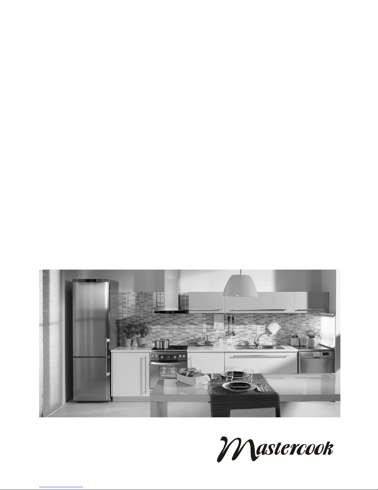
2.5 Opis elementów kuchni (1.1.1)
1 – płyta grzejna
2 – piekarnik elektryczny
3 – panel sterujący
4 – drzwi piekarnika
5 – pojemnik na naczynia lub osłona
6 – palnik mały
7 – palnik średni
8 – palnik duży
9 – ruszt płyty grzejnej
10 – blacha do pieczenia
11 – ruszt do pieczenia
2.6 Panel sterujący (2.6.1)
1 – pokrętła do palników gazowych
2 – pokrętło wyboru funkcji piekarnika
3 – pokrętło regulatora temperatury
4 – lampka kontrolna pracy piekarnika
5 – lampka kontrolna regulatora temperatury
6 – elektroniczny programator
Na rysunku 1.1.1 pokazano urządzenie, które Pań-
stwo posiadacie.
Niniejszy sprzęt nie jest przeznaczony do 1.
użytkowania przez osoby (w tym dzieci) o
ograniczonej zdolności zycznej, czuciowej
lub psychicznej, lub osoby nie mające doświadczenia lub znajomości sprzętu, chyba
że odbywa się to pod nadzorem lub zgodnie z
instrukcją użytkowania sprzętu, przekazanej
przez osoby odpowiadające za ich bezpieczeństwo. Należy zwracać uwagę na dzieci,
aby nie bawiły się sprzętem.
Kuchnię należy zainstalować zgodnie z obo-2.
wiązującymi przepisami i użytkować tylko w
odpowiednio wentylowanym pomieszczeniu.
Elementy opakowania prosimy trzymać z dala 3.
od dzieci, ponieważ mogą być dla nich niebezpieczne.
Wyrób należy instalować po 8 godzinach se-4.
zonowania w pomieszczeniu kuchennym.
Przed zainstalowaniem urządzenia upewnić 5.
się, czy lokalne warunki dystrybucji (rodzaj
i ciśnienie gazu) i nastawy są odpowiednie.
Warunki nastawy urządzenia są podane na tabliczce znamionowej.
Urządzenie to nie jest podłączane do prze-6.
wodów odprowadzających spaliny. Powinno
być ono zainstalowane i przyłączone zgodnie
z aktualnymi przepisami instalacyjnymi. W
szczególności należy uwzględnić odpowiednie wymagania dotyczące wentylacji.
Podłączenie kuchni do wewnętrznej instalacji 7.
gazowej lub do butli z gazem płynnym oraz
jej regulację powinien wykonać wyłącznie
uprawniony instalator urządzeń gazowych
lub technik autoryzowanego zakładu serwisowego, co winno być potwierdzone na karcie
gwarancyjnej wyrobu. Brak takiego potwierdzenia unieważnia gwarancję.
W przypadku awarii urządzenia, zwłaszcza 8.
przy ulatnianiu się gazu lub wystąpieniu zwarcia, urządzenie należy wyłączyć i niezwłocznie
Kuchnie spełniają wymagania następujących dyrektyw:
2006/95/WE – Niskonapięciowe wyroby elektryczne
2004/108/WE – Kompatybilność elektromagnetyczna
90/396/EEC – Zasadnicze wymagania dla urządzeń spalających paliwa gazowe [GAD]
WAŻNE !
Przed zainstalowaniem i użytkowaniem kuchni prosimy dokładnie
przeczytać instrukcję obsługi. Instrukcja zawiera ilustracje a numery
ilustracji odpowiadają numeracji punktów w tekście.

5
PL
skontaktować się z autoryzowanym zakładem
serwisowym. Uszkodzonej kuchni nie wolno
użytkować.
Producent nie ponosi odpowiedzialności za 9.
obrażenia lub uszkodzenia spowodowane
przez nieprawidłowe zainstalowanie urządzenia, podłączenie do niesprawnej instalacji gazowej lub elektrycznej lub jego nieprawidłowe
użytkowanie.
Nie zezwala się na wykonywanie we własnym 10.
zakresie jakichkolwiek napraw z wyjątkiem
wymiany oświetlenia piekarnika, pod rygorem utraty uprawnień gwarancyjnych.
Kuchni nie wolno podnosić za uchwyt drzwi 11.
piekarnika
.
Producent zastrzega sobie możliwość wpro-12.
wadzania zmian w celu unowocześniania
wyrobu i stałego polepszania jakości, bez
uprzedniego powiadomienia użytkowników.
Zmiany te jednak nie będą stwarzały trudności przy obsłudze.
Podczas użytkowania kuchnia staje się gorąca. •
Zaleca się zachować ostrożność i unikać dotykania
gorących elementów wewnątrz piekarnika. Szczególną uwagę prosimy zwrócić na dzieci.
Przewody przyłączeniowe zmechanizowanego •
sprzętu gospodarstwa domowego używanego w
pobliżu włączonej kuchni, powinny być z dala od
jej gorących elementów. Należy zwrócić uwagę,
aby przewody te nie zostały przyciśnięte gorącymi
drzwiami piekarnika.
Do zestawiania potraw z płyty grzejnej i wyjmowa-•
nia form z piekarnika należy używać suchych ręka-
wic ochronnych.
Nie pozostawiać bez nadzoru urządzenia z zapa-•
lonymi palnikami, zwłaszcza podczas smażenia,
gdyż przegrzany tłuszcz może się zapalić.
Przedmioty łatwopalne przechowywać z dala od •
palników.
W piekarniku i w pojemniku na naczynia nie prze-•
chowywać przedmiotów łatwopalnych i wrażliwych
na działanie podwyższonej temperatury.
Nie przeciążać otwartych drzwi piekarnika. Nie •
wolno na nich siadać ani stawać.
Przed otwarciem drzwi piekarnika należy się od •
niego odsunąć, aby nagromadzone gorące powietrze mogło sie rozproszyć.
Na płycie grzejnej nie używać naczyń kuchennych, •
które wystają poza jej brzegi.
Użytkowanie urządzenia do gotowania i piecze-•
nia powoduje wydzielanie się ciepła i wilgoci w
pomieszczeniu, w którym jest ono zainstalowane.
Należy upewnić się, czy pomieszczenie kuchenne jest dobrze przewietrzane. Należy utrzymywać
otwarte naturalne otwory wentylacyjne lub zainstalować środki wentylacji mechanicznej (okap z mechanicznym wyciągiem).
Długotrwałe intensywne użytkowanie urządzenia •
może wymagać dodatkowego przewietrzania, na
przykład otwarcia okna lub bardziej skutecznej
wentylacji, np. zwiększenia wydajności wentylacji
mechanicznej, jeśli jest stosowana.
Zabrania się samowolnie dokonywać przeróbek •
kuchni na inny rodzaj gazu, dokonywać zmian w
instalacji gazowej i elektrycznej urządzenia.
Urządzenia nie wykorzystywać do ogrzewania po-•
mieszczeń.
W przypadku ulatniania się gazu należy na-
tychmiast zamknąć zawór na instalacji gazowej lub na butli z gazem, dokładnie przewietrzyć pomieszczenie i wezwać pogotowie
gazowe. W tym czasie nie wolno zapalać zapałek, palić papierosów, włączać bądź wyłączać
odbiorników elektrycznych (radio, dzwonek,
włącznik oświetlenia) lub mechanicznych powodujących iskrzenie.
W przypadku zapalenia się gazu uchodzącego
z nieszczelnego zaworu butli z gazem należy
zarzucić na butlę mokry koc, w celu ostudzenia butli i zakręcić zawór na butli. Zabrania
się używania uszkodzonej butli !
Na rusztach nie stawiać zdeformowanych lub –
niestabilnych naczyń, gdyż mogą się przewrócić
i zalać palniki.
Nie stawiać pustych naczyń nad włączonym pal- –
nikiem.
Przed zdjęciem naczyń z palników należy zmniej- –
szyć płomień lub zgasić go całkowicie.
Palniki utrzymywać w należytej czystości. Nie –
dopuszczać do wykipienia potraw i zalewania
palników.
6.1.Po rozpakowaniu urządzenia sprawdzić, czy nie
ma ono widocznych uszkodzeń. Jeśli kuchnia
została uszkodzona podczas transportu nie wol-
6
PL
no jej podłączać.
6.2 Z kuchni usunąć ewentualne naklejki i dokładnie
umyć ją z resztek kleju po naklejkach.
6.3 Pomieszczenie kuchenne powinno być suche i
powinno mieć dobrą wentylację.
6.4 Ustawienie urządzenia powinno gwarantować
swobodny dostęp do wszystkich elementów sterowania. Nie zaleca się ustawiania kuchni na
podstawie.
6.5 Urządzenie powinno być zainstalowane z dala od
materiałów łatwopalnych. Ściana pomieszczenia
przylegająca do kuchni powinna być wykonana z
materiałów niepalnych.
6.6 Nad kuchnią powinna być wolna przestrzeń dla
odpływu oparów kuchennych. Najlepiej zamontować okap nadkuchenny, który będzie absorbować lub odprowadzać te opary. Odległość pomiędzy okapem i płytą grzejną powinna wynosić
co najmniej 650mm (6.6.1).
6.7 Nie wolno zawieszać górnych szafek kuchennych bezpośrednio nad kuchnią.
6.8 Kuchnia jest wyposażona w regulowane nóżki
służące do jej poziomowania. Nóżki są dostępne po przechyleniu kuchni (6.8.1) lub po wyjęciu
pojemnika na naczynia (6.8.2). Nóżki obracać w
jedną lub drugą stronę, zależnie od potrzeby.
Kuchnia jest zaopatrzona w rurowy króciec z •
gwintem G½”. Do króćca podłączyć gaz z zastosowaniem odpowiedniego osprzętu.
Kuchnię można podłączyć do wewnętrznej insta-•
lacji domowej lub do butli z gazem płynnym.
Przed przystąpieniem do czynności podłączania •
kurek gazowy powinien być zamknięty.
Połączenie zaleca się uszczelnić taśmą teono-•
wą.
7.1 Podłączenie do gazu ziemnego
Kuchnię można podłączyć do instalacji gazowej •
na sztywno lub za pomocą elastycznego przewodu metalowego, mającego certykat.
Maksymalna długość przewodu elastycznego nie •
powinna przekraczać 2,0m. Przewód nie powinien stykać się z żadnymi częściami ruchomymi
i nie powinien przechodzić przez przestrzeń, w
której nie ma wystarczająco dużo miejsca.
Przy podłączaniu do sztywnej instalacji rurowej •
należy zwrócić uwagę, aby nie wywołać naprężeń w żadnym punkcie instalacji ani w żadnej
części urządzenia.
7.2 Podłączenie do gazu płynnego
Jeżeli użytkownik zamierza korzystać z butli z •
gazem, kuchni nie należy instalować w piwnicy
lub w innym pomieszczeniu, w którym podłoga
znajduje się poniżej poziomu terenu, ponieważ
gaz płynny jest cięższy od powietrza i zbiera się
na poziomie podłogi.
Do podłączenia urządzenia z butlą należy zasto-•
sować przewód gumowy, posiadający certykat.
Do podłączenia kuchni z przewodem gumowym •
należy zastosować rurę stalową o długości co
najmniej 0,5m.
Przewód gumowy nie powinien być dłuższy niż •
1,5m. Po podłączeniu, z obu stron powinien on
być zabezpieczony opaskami zaciskowymi.
Przewód nie powinien mieć załamań ani przewę-•
żeń i na całej długości powinien być dostępny.
Przewodu nie należy prowadzić w pobliżu źródeł •
wysokiej temperatury (maks. 50
0
C).
Przewód nieszczelny powinien być natychmiast •
wymieniony. Zabrania się napraw nieszczelnego
przewodu.
Po każdorazowym podłączeniu kuchni do butli z gazem należy sprawdzić szczelność zaworu na butli i
połączenie reduktora z butlą oraz jego działanie.
UWAGA !
Niedopuszczalne jest sprawdzanie szczel-1.
ności za pomocą otwartego płomienia (np.
zapałką lub świecą). Grozi to wybuchem! Do
sprawdzenia szczelności można użyć wody z
mydłem.
Okresowo należy sprawdzać stan przewodu i 2.
szczelność połączenia, zgodnie z obowiązującymi przepisami.
Przewód gumowy nie powinien dotykać gorą-3.
cych elementów kuchni.
7.3 Wymiana dysz
W razie konieczności dostosowania kuchni do zasilania innym rodzajem gazu, należy wymienić dysze
i wypełnić etykietę zmiany gazu, która znajduje się
w woreczku z instrukcją obsługi i kartą gwarancyjną.
Po opisaniu, do jakiego rodzaju gazu kuchnia została
przystosowana, etykietę przykleić na urządzeniu.
Wymiana dysz:
zamknąć kurek odcinający instalację gazową lub –
butlę od kuchni,
zamknąć wszystkie kurki w kuchni, –
zdjąć ruszty oraz nakrywki i kołpaki palników. –
odkręcić dotychczasowe dysze i wymienić je na –
nowe wg tabeli 1,
założyć kołpaki i nakrywki palników, –
wyregulować kurki palników, –
sprawdzić szczelność połączeń. –
7
PL
napięcie w sieci odpowiada napięciu podanemu –
na tabliczce znamionowej urządzenia,
sieć elektryczna, do której ma być podłączona –
kuchnia ma wystarczającą moc w porównaniu z
maksymalną mocą pobieraną przez kuchnię, podaną na tabliczce znamionowej urządzenia.
Gniazdo wtykowe powinno być łatwo dostęp-•
ne dla użytkownika.
Prosimy zwrócić uwagę, aby przewód zasila-•
jący nie dotykał gorących elementów kuchni.
Powierzchnie emaliowane i szklane przetrzeć •
miękką, wilgotną ściereczką.
Sprawdzić poprawność ułożenia poszczególnych •
elementów palników.
Z piekarnika wyjąć wyposażenie, zdjąć z niego fo-•
lię i umyć je w wodzie z dodatkiem płynu do mycia
naczyń.
Jeżeli kuchnia jest wyposażona w elektroniczny •
programator, po podłączeniu urządzenia do sieci
należy ustawić czas bieżący. Opis programatora
znajduje się w oddzielnej instrukcji.
Przed pierwszym użyciem kuchni należy zamknąć •
drzwi piekarnika i uruchomić go na ok. 30 minut.
Piekarnik powinien być pusty. Pokrętło wyboru
funkcji ustawić na pozycji
lub , a pokrętłem
regulatora temperatury ustawić 2500C. Powstający
przy tym dym i zapach są nieznaczne, jeśli zadba
się o wystarczającą wentylację pomieszczenia,
np. przez otwarcie okien. Po ostudzeniu, piekarnik
wyczyścić zgodnie z instrukcjami podanymi w rozdziale „Czyszczenie i konserwacja”.
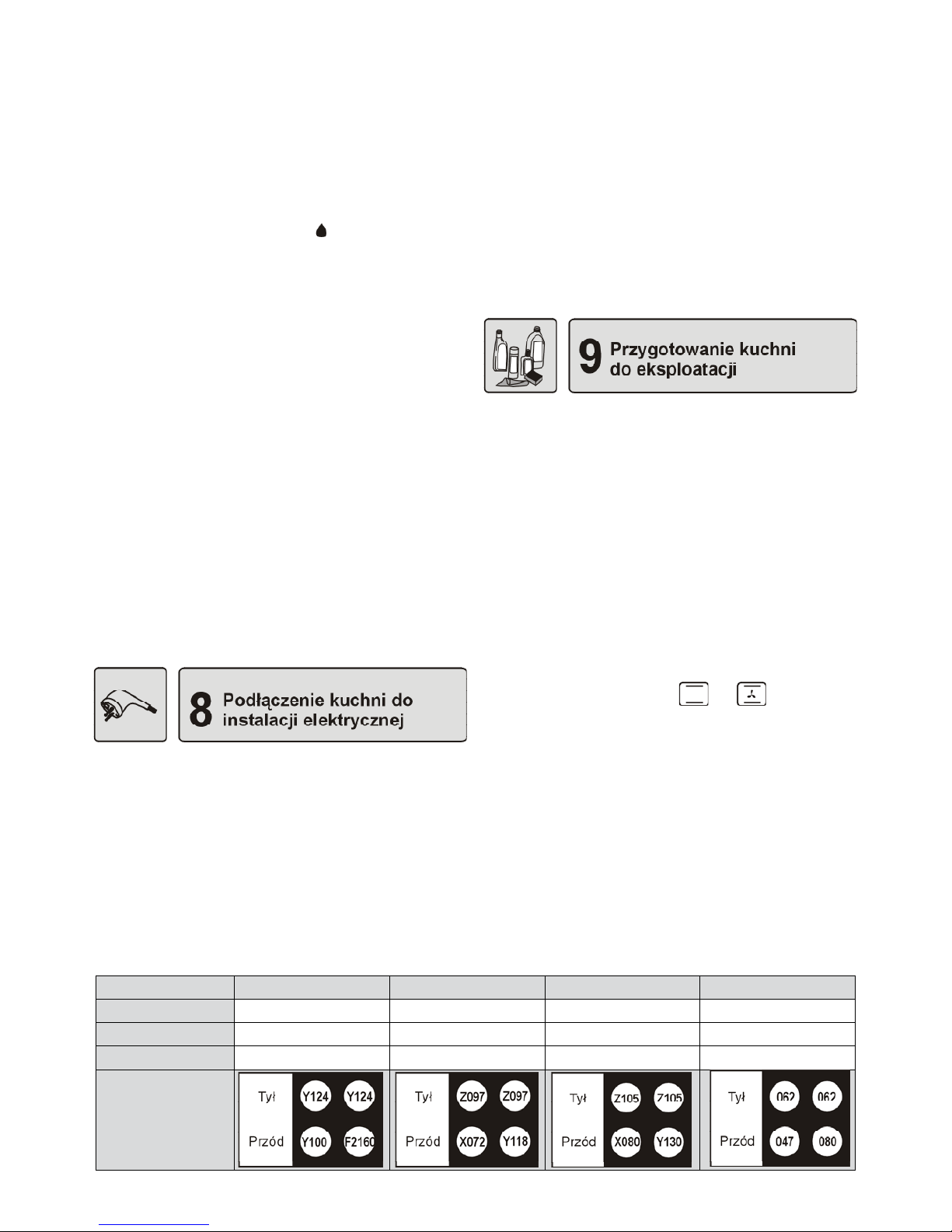
Tabela 1 Oznaczenia dysz
7.4 Regulacja kurków
Regulacja kurka gazowego polega na ustawieniu
płomienia oszczędnościowego palnika.
Regulacja kurków:
pokrętłem otworzyć przepływ gazu i zapalić re- –
gulowany palnik,
pokrętło ustawić na pozycji –
– płomień oszczędnościowy, a następnie nie zmieniając tej pozycji
zdjąć je z trzpienia kurka i obserwować płomień
palnika,
śrubę regulacyjną „ – A” (7.4.1) obracać i obserwować płomień; płomień ustawić na taką wysokość,
aby nie zgasł przy lekkim przeciągu oraz przy
szybkim przestawieniu kurka z płomienia pełnego na oszczędnościowy i odwrotnie,
regulację można uznać za prawidłową, gdy jądro –
płomienia ma kształt stożka koloru zielono-niebieskiego o wysokości ok. 2 – 4mm,
jeżeli w instalacji doprowadzającej gaz wystę- –
pują widoczne zmiany ciśnienia gazu (zmiana
wielkości płomienia przy pełnym przepływie),
płomień oszczędnościowy należy ustawić przy
niskim ciśnieniu w instalacji tak, aby palnik nie
zgasł podczas jego normalnego użytkowania,
po wyregulowaniu kurków, założyć pokrętło i –
zgasić płomień.
Zużycie gazu przy płomieniu minimalnym stanowi
ok. 25% zużycia przy płomieniu pełnym.
8.1 Kuchnie wyposażone w przewód zasilający z
wtyczką powinny być podłączone do gniazdka sieciowego wyposażonego w prawidłowo
podłączony bolec ochronny (8.1.1)
8.2 W kuchniach wyposażonych w przewód zasilający bez wtyczki należy podłączyć wtyczkę.
Przewód podłączyć do wtyczki z prawidłowym uziemieniem. Przed podłączeniem do
sieci należy sprawdzić czy:
2Ls-G2.350 13mbar 2E-G20 20mbar 2Lw-G27 20mbar 3B/P-G30 37mbar
Palnik mały Y100 X072 X080 047
Palnik sredni Y124 Z097 Z105 062
Palnik duży F2 160 Y118 Y130 080
Rozmieszczenie
dysz na płycie
grzejnej

8
PL
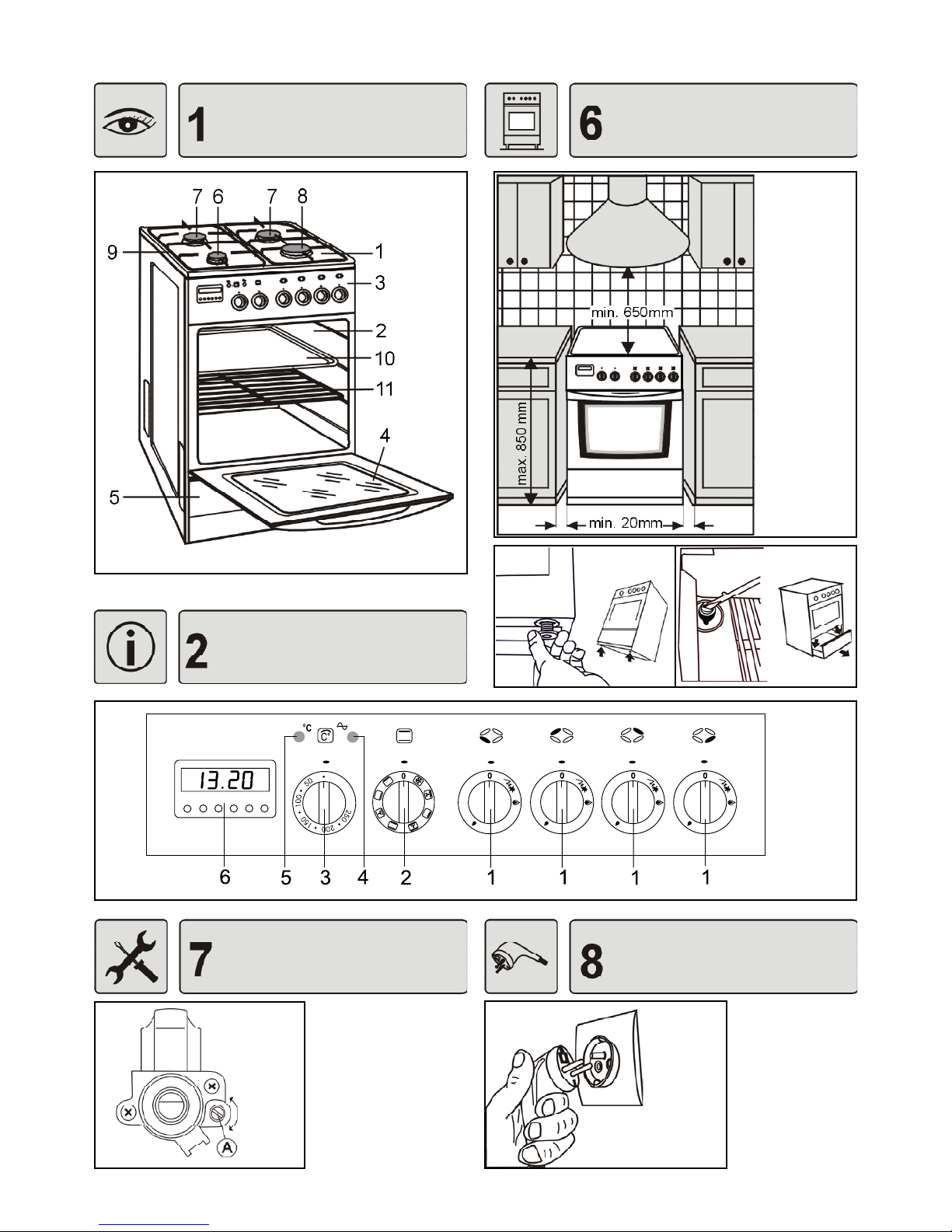
10.1 Palniki gazowe (10.1.1)
A - zapalacz
B - końcówka termopary (zabezpieczenie prze-
ciwwypływowe)
10.2 Pokrętła. Przepływ gazu w palnikach reguluje
się pokrętłami kurków gazowych. Przed włączeniem palnika należy upewnić się, czy pokrętło,
które zamierzamy uruchomić odpowiada palnikowi, który chcemy zapalić. Przyporządkowanie
palników do pokręteł pokazano na rys. (10.2.1).
10.3 Dobór płomienia
Płomień nie powinien wychodzić poza dno na-
czynia. Wielkość płomienia zależy od pozycji pokrętła (10.3.1; 10.3.2; 10.3.3).
0 - palnik zgaszony (przepływ gazu zamknięty)
- płomień duży
- płomień mały (oszczędnościowy)
10.4 Płomienia dużego
(10.3.2) należy używać do
czasu zagotowania potrawy, a do dalszego gotowania należy go zmniejszyć i najlepiej ustawić
na pozycji płomień oszczędnościowy (10.3.3).
Wielkość płomienia należy regulować tylko w za-
kresie pomiędzy pozycją
i (10.4.1).
10.5 Zapalanie palników
Kuchnie są wyposażone w urządzenie odcinające
dopływ gazu do palnika po zaniku płomienia np. po
zalaniu palnika potrawą.
Pokrętło wybranego palnika obrócić przeciwnie –
do kierunku ruchu wskazówek zegara, nacisnąć
je i przytrzymać wciśnięte do oporu tak długo, aż
zapali się gaz (10.5.1),
Po zapaleniu gazu pokrętło trzymać wciśnięte –
do oporu jeszcze ok. 5 sek. celem zadziałania
zabezpieczenia,
zwolnić nacisk na pokrętło i ustawić żądaną wiel- –
kość płomienia.
W razie przypadkowego zaniku płomienia zamknąć kurek palnika i nie ponawiać próby zapłonu przez co najmniej 1 minutę.
10.6 Gaszenie palników
Pokrętło obrócić zgodnie z kierunkiem ruchu wskazówek zegara i ustawić je na pozycji „0”.
10.7 Zapalanie palników przy zasilaniu gazem
płynnym z butli
Przed zapaleniem pierwszego palnika, otworzyć za-
wór na butli gazowej a następnie zapalić gaz jak podano powyżej.
Przy zamykaniu dopływu gazu, przed zgaszeniem
ostatniego palnika należy:
zamknąć zawór na butli gazowej, –
po zgaszeniu płomienia zamknąć kurek tego pal- –
nika.
W czasie gdy kuchnia nie jest używana, zawór butli
gazowej powinien być zamknięty
.
10.8 Dobór naczyń
Średnica dna naczynia powinna być 2,5 – 3 razy •
większa od korony palnika (10.8.1). Naczynia nie
powinny wystawać poza ruszt a płomień nie powinien wychodzić poza dno naczynia (10.8.2).
Naczynia zawsze powinny być czyste i suche, po-•
nieważ wtedy dobrze przewodzą i zatrzymują ciepło.
W czasie gotowania naczynia powinny być przy-•
kryte pokrywkami, co zapobiegnie gromadzeniu
się nadmiernej ilości oparów w pomieszczeniu kuchennym.
Minimalne wymiary naczyń• :
Dla palnika małego - f 90mm
Dla palnika średniego - f 160mm
Dla palnika dużego - f 200mm
11.1 Elementy piekarnika (11.1.1)
[1], [2], [3], [4], [5] – poziomy prowadnic
1 – grzałka górna
2 – grzałka opiekacza
3 – grzałka dolna
4 – lampka oświetlenia piekarnika
5 – perforowana osłona
6 – czujnik temperatury
11.2 Pokrętło wyboru funkcji (11.2.1) umożliwia
wybranie najbardziej odpowiedniej funkcji dla
danej potrawy. Można je obracać w obie strony.
Poniżej są opisane funkcje piekarnika.
Ogrzewanie z góry
Funkcja służy do mocniejszego zapiekania potraw od góry.
Ogrzewanie od dołu
Ciepło oddaje grzałka dolna, usytuowana pod
podłogą piekarnika. Tę funkcję włączamy, gdy
chcemy dopiec spód potrawy. Zaleca się ją stosować podczas ostatnich 10-15 minut piecze-
nia.

9
PL
Ogrzewanie od dołu z wentylatorem
Wentylator równomiernie rozprowadza ciepło
wytwarzane w dolnej części piekarnika.
Pieczenie tradycyjne
Przy tej funkcji ciepło dochodzi od góry i od dołu.
Potrawy należy umieszczać na jednym poziomie, najlepiej w centralnym miejscu piekarnika.
Doskonale nadaje się do pieczenia ciast, mięsa,
ryb, chleba, pizzy itp.
Pieczenie tradycyjne z wentylatorem
Wentylator wymusza cyrkulację gorącego powietrza wokół potrawy. Przy tej metodzie wybrać
temperaturę niższą niż przy pieczeniu tradycyjnym.
Opiekanie tradycyjne
Funkcja przeznaczona do opiekania potraw o
małych rozmiarach (steki, szaszłyki, kiełbaski,
ryby, tosty, grzanki, zapiekanki itp.).
Potrawę należy umieścić na blasze lub ruszcie,
w środkowej części.
Czas opiekania przyjmuje się orientacyjnie od
8–10 minut na każdy centymetr grubości. Piekarnik powinno się wstępnie rozgrzać przy maksymalnej temperaturze. Opiekane porcje, po
upływie połowy czasu powinno się przewrócić
na drugą stronę.
Przy opiekaniu mięsa na ruszcie zaleca się na
niższym poziomie umieścić blachę do zbierania ociekającego tłuszczu i wlać do niej ok. 0,5l
wody.
Opiekanie z wentylatorem
Funkcja umożliwiająca opiekanie z równomiernym rozprowadzaniem ciepła przez wentylator.
Rozmrażanie
Przy tej funkcji jest włączony wentylator, który wymusza obieg powietrza wokół potrawy. W
ten sposób uzyskuje się jednorodne rozmrażanie produktów spożywczych. Tę metodę można
stosować do wszystkich zamrożonych potraw.
Mrożone warzywa można piec od razu, bez rozmrażania.
11.3 Pokrętło regulatora temperatury (11.3.1)
Regulator temperatury umożliwia ustawienie i
automatyczne utrzymywanie temperatury w piekarniku na zadanym poziomie.
Na pokrętle oznaczono nastawy, które odpowiadają temperaturom w piekarniku (po nagrzaniu).
Ustawienie temperatury – pokrętło obrócić w
prawo i ustawić na żądanej pozycji z zakresu
50–250
0
C.
Po zakończeniu pieczenia – pokrętło obrócić w
lewo i ustawić je na pozycji zerowej „•”.
11.4 Lampki kontrolne (panel 2.6.1)
Lampka kontrolna pomarańczowa• sygnalizuje
pracę piekarnika. Lampka włącza się zawsze po
wybraniu dowolnej funkcji piekarnika, a gaśnie
po ustawieniu pokrętła wyboru funkcji na pozycji
„0”.
Lampka kontrolna czerwona• sygnalizuje dzia-
łanie regulatora temperatury. Lampka włącza się
po ustawieniu dowolnej temperatury a gaśnie po
uzyskaniu ustawionej temperatury. Następnie
będzie się zapalać i gasnąć w trakcie pieczenia,
sygnalizując włączanie i wyłączanie grzałek w
celu utrzymania temperatury.
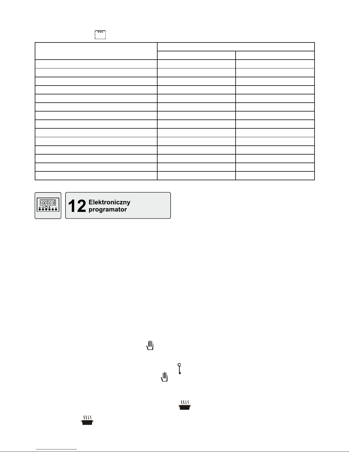
11.5 Elektroniczny programator
Programator umożliwia sterowanie pracą piekarnika
w cyklu automatycznym lub półautomatycznym.
Zastosowanie programatora nie wyklucza możliwości ręcznego sterowania pracą piekarnika.
Opis programatora znajduje się w oddzielnej instruk-
cji.
11.6 Lampka oświetlenia piekarnika
Dla Państwa bezpieczeństwa i wygody, w piekarniku
podczas pieczenia jest włączona lampka. Lampka
włącza się po wybraniu dowolnej funkcji piekarnika.
Po wyłączeniu piekarnika lampka gaśnie.
11.7 Akcesoria
Kuchnie są standardowo wyposażone w jedną lub
dwie blachy (11.7.1) i ruszt do pieczenia (11.7.2).
Ruszt służy do stawiania na nim wszelkich naczyń z
potrawą przeznaczoną do pieczenia lub zapiekania.
Można na nim również kłaść niektóre potrawy np.
mięso, kiełbaski, ryby. W takim przypadku pod rusztem należy umieścić blachę na ociekający tłuszcz i
wlać do niej ok. 0,5l wody, wtedy piekarnik pozosta-
nie czysty.
11.8 Działanie piekarnika
1. Rozgrzać piekarnik a następnie potrawę umieścić
w naczyniu na odpowiednim poziomie piekarnika
(11.8.1).
2. Pokrętłem wyboru funkcji wybrać sposób ogrzewania piekarnika, np.
(11.8.2).
3. Pokrętłem regulatora temperatury ustawić temperaturę odpowiednią dla potrawy, np. 200
0
C
(11.8.3).
4. W kuchniach z programatorem można zaprogramować pracę piekarnika.

10
PL
5. Po zakończeniu pieczenia pokrętło wyboru funkcji
i pokrętło regulatora temperatury ustawić na po-
zycji zerowej.
Uwaga !
1. Podczas użytkowania piekarnika, nie należy
pozostawiać go bez nadzoru. Dostępne części
kuchni stają się gorące. Nie dopuszczać do
nich dzieci !
2. Potraw nie należy umieszczać na najwyższej
[5] prowadnicy.
11.9 Eksploatacja piekarnika
Do pieczenia ciast można używać tradycyjnych •
foremek blaszanych a także powlekanych teonem, ceramicznych, szklanych i z folii aluminiowej
(11.9.1). Ze względu na różnorodność kształtów i
możliwość zastosowań najbardziej uniwersalne są
foremki blaszane. Przed pierwszym użyciem nową
formę blaszaną powinno się wypiec w silnie rozgrzanym piekarniku, aby utraciła swój zapach.
Foremki należy wypełniać ciastem do 2/3 wysoko-•
ści, pozostawiając wystarczająco dużo miejsca do
wyrośnięcia.
Do pieczenia mięsa można używać naczyń cera-•
micznych, szklanych, stalowych emaliowanych
i żeliwnych, z uchwytami odpornymi na działanie
wysokich temperatur (11.9.2).
Potrawy powinny być wkładane do nagrzanego •
piekarnika.
Podczas pieczenia, ciasto powinno być równo-•
miernie ogrzewane. Ten warunek jest spełniony po
wybraniu funkcji
lub .
Jeżeli wierzch ciasta jest zbyt ciemny, to następ-•
nym razem foremkę z ciastem należy wsunąć na
niższy poziom piekarnika i wybrać niższą temperaturę, lecz nieco dłużej piec.
Jeśli spód ciasta jest zbyt ciemny, to w przyszłości •
wsunąć je wyżej i wybrać niższą temperaturę.
Przy pieczeniu, należy wystrzegać się temperatury •
zbyt wysokiej, ponieważ ciasto nie wyrośnie i może
powstać zakalec. Natomiast zbyt długie trzymanie
ciasta w nagrzanym piekarniku może spowodować
jego przypalenie i wyschnięcie.
Przy doborze temperatury i czasu pieczenia należy •
uwzględnić masę i konsystencję pieczonego cia-
sta.
Naczynia z potrawami należy umieszczać na od-•
powiednim poziomie piekarnika.
Użytkownik kierując się swoimi spostrzeżeniami i •
doświadczeniem sam powinien dobrać najbardziej
optymalny poziom ułożenia potraw oraz temperaturę i tryb pracy piekarnika.
Przy pierwszym pieczeniu najlepiej zaczynać od •
średnich wartości temperatur podanych w recepturach, a w razie potrzeby następnym razem ustawić
temperaturę wyższą lub niższą. Niższa temperatura powoduje bardziej równomierne zrumienienie
wypieku.
Aby sprawdzić, czy wypiek jest gotowy, należy •
na kilka minut przed wyłączeniem piekarnika włożyć do niego drewniany patyczek. Jeśli ciasto nie
przykleja się do patyczka – wypiek jest gotowy. Po
upieczeniu, ciasto pozostawić w piekarniku jeszcze ok. 5 minut.
Podczas użytkowania piekarnika należy przestrze-•
gać poniższych zaleceń:
nie trzymać w piekarniku niepotrzebnego wy- –
posażenia,
formy do ciast i zapiekanek oraz naczynia –
do pieczenia mięsa stawiać na ruszcie a nie
na blasze, w centralnym miejscu piekarnika
(11.9.3 i 11.9.4),
przy wybieraniu parametrów pieczenia należy –
uwzględnić rodzaj naczynia; naczynia w zależności od rodzaju materiału, grubości ścian i
barwy mają różne przewodnictwo cieplne.
Pieczenie mięsa w sosie własnym, najlepiej udaje się
po zastosowaniu funkcji
, szczególnie dla mięsa
chudego. Inne gatunki mięsa, w tym również mielone
i drób można piec przy funkcji
.
Pizza
W piekarniku można upiec pizzę przygotowaną samodzielnie lub pizzę mrożoną.
Pizzę można piec po wybraniu funkcji
w tem-
peraturze ok. 200
0
C. Ciepło rozchodzi się głównie z
dołu. Potrawę umieścić na jednym, najlepiej na [2]
poziomie piekarnika.
Pizzę zamrożoną można wkładać bezpośrednio do
nagrzanego piekarnika.
W przypadku zaobserwowania silnego parowania
w trakcie pieczenia mocno wilgotnych potraw,
zaleca się przykrycie naczynia pokrywą i zdjęcie
jej w końcowej fazie w celu przyrumienienia potrawy,
Ważne !
Poniżej w tabelach podano orientacyjne temperatury i czasy pieczenia dla różnych potraw. W
praktyce mogą występować różnice, które użytkownik powinien skorygować na podstawie własnych doświadczeń. Najlepiej wykonać kilka prób
dla poszczególnych potraw, a następnie zanotować optymalny czas i temperaturę.

11
PL
Wypieki metodą tradycyjną
Tabela 2
Rodzaj wypieku Temperatura [0C] Czas pieczenia [godz:min]
Babka piaskowa 160 - 175 1:15 - 1:20
Babka drożdżowa 175 - 190 0:50 - 1:00
Biszkopt 170 - 180 0:30 - 0:40
Spód pod owoce na kruchym cieście Rozgrzany piekarnik 210 - 220 0:10 - 0:25
Chałka drożdżowa 190 - 200 0:30 - 0:40
Strucla (z jabłkami) 220 0:40 - 0;50
Placek z owocami 200 - 210 0:25 - 0:50
Placek z kruszonką 200 - 220 0;20 - 0;30
Tabela 3
Pieczenie mięsa metodą tradycyjną
Rodzaj mięsa Ilość [kg] Temperatura [0C] Czas pieczenia [godz:min]
Wołowina 1 220 - 250 2:00 - 2:30
Wieprzowina 1 210 - 225 1:30 - 2:00
Cielęcina 1 210 - 225 1:45 - 2:00
Baranina 1 210 - 225 1:30 - 2:00
Dziczyzna (zając) 2 Rozgrzany piekarnik 210 - 230 1:00 - 1:50
Kurczak 1 225 - 250 0:45 - 1:00
Ryby 1 210 - 225 0:45 - 1:00
Pieczenie i duszenie mięsa z wykorzystaniem nawiewu
Tabela 4
Rodzaj mięsa Ilość [kg] Temperatura [0C] Czas pieczenia [godz:min]
Kurczaki 1 180 0:50 - 1:00
Dziczyzna 1 - 1,5 160 2:00 - 2:20
Cielęcina 1 160 1:40 - 2:20
Wieprzowina 1 175 1:50 - 2:00
Wołowina 1 160 2:00 - 2:30
Gęś, kaczka - 175 w zależności od wagi
Wypieki z wykorzystaniem nawiewu
Tabela 5
Rodzaj wypieku Temperatura [0C] Czas pieczenia [godz:min]
Bezy 100 1:00 - 1:10
Babka piaskowa 160 1:05 - 1:10
Babka drożdżowa 160 1:00 - 1:10
Ciasto drożdżowe 175 0:40 - 0:45
Placek z kruszonką 175 0:20 - 0:30
Placek z owocami 175 0:40 - 0:55
Biszkopt 160 0:30 - 0:40
12
PL
Opiekanie na ruszcie
Tabela 6
Rodzaj potrawy
Czas opiekania [min]
1 strona 2 strona
Kotlet i sznycel wieprzowy 8 - 10 6 - 10
Sztuka mięsa wieprzowego 10 - 12 6 - 8
Kiełbaski 8 - 10 6 - 8
Szaszłyki 7 - 8 5 - 6
Stek wołowy 6 - 7 5 - 6
Sztuka mięsa wołowego 10 - 12 10 - 12
Kotlet cielęcy 6 - 8 6 - 8
Stek cielęcy 6 - 7 5 - 6
Kotlet barani 8 - 10 6 - 8
Kurczak - połówka 10 - 15 (strona wewn.) 10 - 12 (strona zewn.)
Filet z ryby 6 - 7 4 - 5
Pstrąg 4 - 7 6
Grzanki 2 - 3 2 - 3
Tosty 3 - 5 2 - 3
12.1. Uwagi ogólne
Elektroniczny programator cyfrowy steruje pracą piekarnika. Programator wskazuje aktualny czas z dokładnością do 1 minuty. Po każdym zrealizowanym
programie emituje sygnał dźwiękowy i samoczynnie
wyłącza piekarnik.
Programator umożliwia realizację następujących
funkcji:
ustawienie czasu bieżącego,•
ustawienie czasu trwania pieczenia,•
ustawienie godziny wyłączenia piekarnika, •
ustawienie czasu trwania pieczenia i godziny wy-•
łączenia kuchni w cyklu 24-godzinnym,
ustawienie minutnika,•
Możliwe jest sterowanie pracą piekarnika bez udziału programatora, po naciśnięciu przycisku
.
Jeżeli program automatycznego sterowania został
zakończony, a potrawa wymaga dalszego pieczenia,
wówczas pracę piekarnika można ponownie zapro-
gramować lub nacisnąć przycisk pracy ręcznej
i
kontrolować dalsze pieczenie.
Programator może działać jako minutnik, przy czym
minutnik działa niezależnie od programu.
Programowanie polega na naciśnięciu przycisku wy-
branej funkcji np.
i ustawieniu żądanego czasu
przyciskiem „+”. Przyciskiem „-” czas można skorygować.
Krótkotrwałe naciśnięcie przycisków „+” lub „-” powoduje zmianę czasu o jedną minutę, zaś dłuższe ich
przytrzymanie - włączenie trybu szybkiego przewija-
nia.
Programowanie:
nacisnąć i zwolnić przycisk wybranej funkcji,•
w czasie do 5 sekund po zwolnieniu przycisku funk-•
cji, przyciskami „+” i ewentualnie „-” ustawić wymagany czas; jeżeli w czasie tych 5s programowanie
nie zostanie rozpoczęte - wywołana funkcja znika,
po ok. 5s od zakończenia programowania, progra-•
mator wyświetla czas bieżący i zaczyna realizować
program.
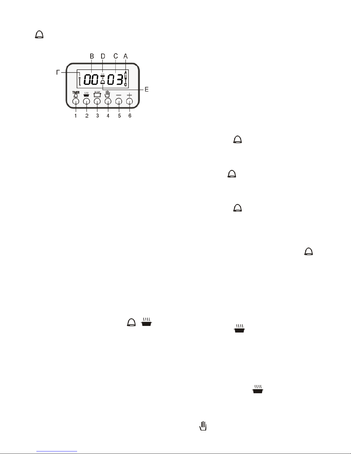
Na wyświetlaczu programatora pojawiają się następujące symbole graczne:
„AUTO” - Symbol pracy automatycznej
Ciągłe świecenie oznacza, że jest wykonywany program. Pulsowanie informuje o zakończeniu programu.
- Symbol blokady
Piekarnik można zabezpieczyć przed zmianą nastaw
lub przypadkowym włączeniem, zwłaszcza przez
dzieci.
- Symbol pracy piekarnika
Ciągłe świecenie sygnalizuje pracę piekarnika (o ile
jest on załączony).
13
PL
- Symbol minutnika
Ciągłe świecenie oznacza, że ustawiono minutnik.
A – praca automatyczna
B – godziny
C – minuty
D – symbol pracy piekarnika
E – symbol minutnika
F – symbol blokady
1 - przycisk minutnika
2 - przycisk czasu trwania
3 – przycisk godziny zakończenia
4 - przycisk pracy ręcznej
5 - przycisk nastawy zmniejszania czasu „-”;
6 - przycisk nastawy zwiększania czasu „+”
Po przyłączeniu kuchni do sieci zasilającej na 1.
wyświetlaczu programatora pojawiają się pulsujące „0.00” oraz „AUTO”.
Pierwszą czynnością jaką należy wykonać po 2.
podłączeniu kuchni do zasilania jest ustawienie czasu bieżącego.
Czas bieżący należy ustawić również po zaniku 3.
napięcia w sieci, trwającego dłużej niż 5s.
Dokładność wskazań programatora zależy od 4.
parametrów sieci zasilającej, dlatego okresowo należy go korygować, porównując z innym
zegarem.
12.2 Ustawienie czasu bieżącego
jednocześnie nacisnąć przyciski –
i ,
przyciskiem „ – +” (i ewentualnie „-”) ustawić żądany
czas np. 11.38,
po ustawieniu czasu zwolnić wszystkie przyciski. –
W czasie ok. 5s od zwolnienia przycisków czas zostanie zapamiętany. Na wyświetlaczu ukazuje się
ustawiony czas. Po ustawieniu czasu bieżącego
kuchnia pracuje w trybie ręcznym.
12.3 Wyłączenie sygnału dźwiękowego
Po zakończeniu każdego programu, piekar-•
nik automatycznie wyłącza się, a włącza się
sygnał dźwiękowy.
Po pewnym czasie sygnał dźwiękowy sam •
się wyłącza.
Użytkownik może wcześniej wyłączyć sygnał •
dźwiękowy naciskając dowolny przycisk programatora.
12.4 Minutnik
Minutnik służy do dźwiękowej sygnalizacji po upływie ustawionego czasu. Można go wykorzystać przy
wykonywaniu krótkotrwałych czynności kulinarnych
(np. gotowanie jaj). Minutnik można ustawić w trakcie realizowania dowolnego programu. Minutnik nie
wyłącza piekarnika.
Ustawienie minutnika:
nacisnąć przycisk –
,
przyciskami: „ – +” i ewentualnie „-” ustawić żądany
czas (np. 3 minuty).
Po ok. 5 s na wyświetlaczu ukaże się czas bieżący
i świeci wskaźnik
. Po upływie zadanego czasu
(tj. 3 minuty) włącza się sygnał dźwiękowy. Sygnał
można wyłączyć naciskając dowolny przycisk.
Kasowanie nastawy minutnika:
nacisnąć przycisk –
,
nacisnąć przycisk „ – -” i przytrzymać go, aż do pojawienia się na wyświetlaczu komunikatu „0.00”,
UWAGA !
Aby sprawdzić ile czasu pozostało do końca
pracy minutnika należy nacisnąć przycisk
Naciśnięcie tego przycisku nie przerywa odmierzania czasu.
12.5 Programowanie czasu trwania pieczenia
Po zaprogramowaniu czasu trwania pieczenia i wybraniu funkcji piekarnika, piekarnik włącza się natychmiast.
Programowanie czasu pracy:
nacisnąć przycisk –
,
przyciskami „ – +” i ewentualnie „-” ustawić żądany
czas pracy np. 35 minut
Po upływie ustawionego czasu:
automatycznie wyłącza się piekarnik, –
włącza się sygnał dźwiękowy, –
na wyświetlaczu programatora pulsuje symbol –
„AUTO” i gaśnie symbol
.
Jeżeli istnieje potrzeba dalszej pracy piekarnika (np.
w celu dopieczenia ciasta) wówczas można ponownie zaprogramować czas lub nacisnąć przycisk pracy
ręcznej
i kontrolować dalszą pracę piekarnika.
14
PL
12.6 Programowanie godziny zakończenia pie-
czenia
Tej funkcji najczęściej używa się z funkcją programowanie czasu trwania pieczenia.
Programowanie godziny wyłączenia:
nacisnąć przycisk –
,
przyciskami „ – +” i ewentualnie „-” ustawić godzinę
wyłączenia piekarnika np. 11.50.
Po upływie ustawionego czasu:
piekarnik automatycznie wyłącza się, –
włącza się sygnał dźwiękowy, –
na wyświetlaczu programatora pulsuje „ – AUTO”.
Jeżeli potrawa nie jest dostatecznie upieczona,
można ponownie zaprogramować czas pracy jak w
punkcie powyżej lub ustawić godzinę wyłączenia pie-
karnika albo nacisnąć przycisk pracy ręcznej
i
kontrolować dalszą pracę piekarnika.
12.7 Sterowanie automatyczne
Praca w cyklu automatycznym polega na zaprogramowaniu czasu trwania pieczenia i godziny wyłącze-
nia piekarnika.
Piekarnik o określonej godzinie samoczynnie włączy
się, a po upływie nastawionego czasu automatycznie
wyłączy się.
Przykład:
Pieczenie wołowiny:
aktualny czas na zegarze - godzina 13.00 –
wymagany czas pieczenia 2 godziny –
temperatura pieczenia 220 –
0
C
potrawę przygotować na godzinę 17.00 –
Mięso włożyć do brytfanny, dodać ok. 10 łyżek •
wo-dy i przykryć pokrywką. Następnie brytfannę
włożyć do piekarnika, ustawić na ruszcie na wybranym poziomie i zamknąć drzwi piekarnika.
Pokrętłem wyboru funkcji wybrać pozycję •
,
a pokrętłem regulatora temperatury ustawić temperaturę 2200C.
Nacisnąć przycisk •
a następnie przyciskami
„+” i ewentualnie „-” odmierzyć czas trwania pie-
czenia tj. 2 godziny.
Nacisnąć przycisk •
i przyciskami „+” oraz
ewentualnie „-” ustawić godzinę 17.00 (czas zakończenia pieczenia.
1. Praca piekarnika została zaprogramowana i odbędzie się automatycznie.
2. O godzinie 15.00 piekarnik samoczynnie włączy
się i będzie pracować przez 2 godziny. O godzinie 17.00 urządzenie samoczynnie wyłączy się,
co jest sygnalizowane sygnałem dźwiękowym. W
tym czasie pulsuje „AUTO” i gaśnie
.
3. Jeżeli potrawa nie została dostatecznie upieczona, pracę piekarnika można ponownie zaprogra-
mować lub nacisnąć przycisk pracy ręcznej
i
kontrolować dalsze pieczenie.
UWAGA !
Naciśnięcie przycisku •
w czasie pracy
piekarnika pozwoli na wyświetlenie zaprogramowanej godziny wyłączenia.
Po naciśnięciu przycisku •
jest wyświetlany zaprogramowany czas trwania pieczenia. Jeżeli piekarnik już rozpoczął pracę, to
ukaże się czas jaki pozostał do zakończenia
programu.
Niemożliwe jest wprowadzanie czasów nie-•
logicznych. Tzn. jeśli na programatorze aktualnie jest godzina 12.00, a wymagany czas
pieczenia wynosi 1 godzina 30 minut to czasu zakończenia pieczenia nie można ustawić
wcześniej niż na 13.30.
12.8 Zmiana nastaw
Zmianę nastawy można przeprowadzić w czasie do
5s od rozpoczęcia programowania lub po skasowaniu programu.
Zmiana czasu trwania lub godziny wyłączenia piekarnika:
nacisnąć przycisk danej funkcji np. –
lub ,
przyciskami „ – +” i „-”ustawić nowy czas.
12.9 Kasowanie nastaw
nacisnąć przycisk danej funkcji np. –
lub ,
nacisnąć przycisk „ – -” i przytrzymać go, aż do pojawienia się na wyświetlaczu komunikatu „0.00”.
Po skasowaniu programu, pracę piekarnika można
ponownie zaprogramować.
12.10 Sterowanie ręczne
UWAGA !
Naciśnięcie przycisku
spowoduje przejście
do trybu pracy ręcznej. Oznacza to, że grzałki
piekarnika włączają się na czas nieokreślony i
użytkownik musi kontrolować dalsze pieczenie.
W celu wyłączenia piekarnika pokrętło wyboru
funkcji należy ustawić na pozycji zerowej.
Jeżeli w trakcie trwania programu, użytkownik •
zamierza przejść do trybu pracy ręcznej, należy
skasować program i nacisnąć przycisk
.
15
PL
Naciśnięcie przycisku • wyłącza funkcje programatora. Piekarnik obsługuje się wtedy wyłącznie
pokrętłem wyboru funkcji i pokrętłem regulatora
temperatury.
Przy sterowaniu ręcznym można korzystać z mi-•
nutnika.
12.11 Funkcja blokowania
Funkcja ta umożliwia zabezpieczenie przed ingerencją dzieci. Oznacza to, że po ustawieniu tej funkcji,
dziecko może wybrać na programatorze dowolny
program, ale program nie będzie aktywny. Przed
przystąpieniem do czynności zabezpieczania, pro-
gramator powinien być w trybie pracy ręcznej
.
Blokowanie programatora:
jednocześnie nacisnąć przyciski –
oraz i
przytrzymać je w tej pozycji ok. 8 sekund, aż do
pojawienia się na wyświetlaczu napisu „ON”,
nacisnąć przycisk „ – +”,
na wyświetlaczu pojawia się napis „ – OFF” i świeci
symbol blokady
,
po upływie ok. 5s na wyświetlaczu obok symbolu –
blokady
pojawia się czas bieżący; piekarnik jest
zablokowany.
Odblokowanie programatora:
programator powinien być w trybie ręcznym, –
jednocześnie nacisnąć przyciski –
oraz i
przytrzymać je w tej pozycji ok. 8 sekund, aż do
pojawienia się na wyświetlaczu napisu „OFF”,
nacisnąć przycisk „ – +”,
na wyświetlaczu pojawia się napis „ – ON” i gaśnie
symbol blokady
,
po upływie ok. 5s na wyświetlaczu pojawi się po- –
nownie czas bieżący; piekarnik jest odblokowany.
12.12 Zmiana intensywności świecenia
W godzinach pomiędzy 22.00 i 5.59 programator
samoczynnie redukuje intensywność świecenia wyświetlacza.
W tych godzinach, wyświetlacz świeci intensywnie
tylko wtedy gdy:
minutnik odmierza czas, –
aktualnie jest wykonywany program, –
naciśnięto dowolny przycisk. –
UWAGA !
Przed przystąpieniem do czyszczenia, kuchnię
odłączyć od sieci elektrycznej.
13.1 Uwagi ogólne
Kuchnię należy systematycznie czyścić. Do •
czyszczenia nie należy stosować gruboziarnistych środków rysujących powierzchnie, drucianych gąbek, agresywnych środków chemicznych
i ostrych przedmiotów.
Części z blachy nierdzewnej, pokrętła i tablicę •
rozdzielczą czyścić łagodnymi płynami, nie zawierającymi środków ściernych.
Powierzchnie emaliowane czyścić miękką ście-•
reczką lub gąbką zwilżoną w ciepłej wodzie z delikatnym detergentem, unikając nadmiaru wody.
Silne zabrudzenia usuwać specjalnymi środkami
do czyszczenia kuchni.
Nie używać szorstkich środków czyszczących •
lub metalowych przedmiotów do czyszczenia powierzchni szklanych, gdyż mogą je porysować,
co może doprowadzić do popękania szkła.
Powierzchnia płyty wokół palników zawsze powin-•
na być czysta, gdyż zanieczyszczenia pogarszają spalanie mieszanki gazowej. Przy czyszczeniu
płyty grzejnej nie dopuszczać do przedostania
się wody pod płytę.
Palniki i zapalacze zawsze powinny być czyste i •
suche, co zapewni ich prawidłowe działanie.
Zanieczyszczone ruszty zdjąć z płyty grzejnej, •
wymoczyć je w ciepłej wodzie z detergentem, a
następnie umyć i osuszyć.
Blachy i foremki do pieczywa oraz blachy do •
pieczenia mięsa i brytfanny, zaraz po użyciu wymoczyć w ciepłej wodzie z dodatkiem płynu do
mycia naczyń kuchennych, starannie je umyć i
wytrzeć do sucha.
Prosimy kontrolować czystość uszczelki drzwi •
piekarnika.
13.2 Czyszczenie palników
UWAGA !
Palniki i zapalacze należy czyścić po każdorazowym zalaniu potrawą a także okresowo, usuwając z nich naloty i zanieczyszczenia.
Elementy palnika (13.2.1)
1 – nakrywka 4 – dysza
2 – kołpak 5 – zapalacz
3 – korpus 6 – termopara

16
PL
Demontaż drzwi piekarnika
Drzwi całkowicie otworzyć, –
Unieruchomić oba zawiasy (13.4.1) po obu stro- –
nach drzwi przez założenie obejmy 1 na zaczep
2 pałąka 3 zawiasu (13.4.2),
Następnie drzwi chwycić oburącz, powoli je ob- –
racać w kierunku zamykania o kąt 45
0
i wycią-
gnąć zawiasy z gniazd (13.4.3).
UWAGA !
1. Pałąk zawiasu jest napięty ze znaczną siłą i
dlatego podczas wyjmowania drzwi piekarnika
należy zachować ostrożność, aby nie przyciąć
sobie palców.
2. Zabrania się czyścić piekarnik urządzeniami
do wytwarzania pary pod ciśnieniem.
W przypadku zabrudzenia klosza lampki piekarnika należy go wykręcić, umyć i wytrzeć do sucha
(13.4.4).
Piekarniki są pokryte emalią ceramiczną.•
Piekarnik czyścić środkami do czyszczenia kuch-•
ni.
Do czyszczenia trudnych do usunięcia zapieczeń •
można użyć specjalnych środków przeznaczonych
do czyszczenia piekarników. Preparaty te są jednak żrące i dlatego należy ich używać minimalnie
i bardzo ostrożnie, przestrzegając zaleceń producenta tych środków.
UWAGA !
Przed przystąpieniem do usuwania usterek, aby
uniknąć możliwości porażenia prądem elektrycznym, kuchnię odłączyć od sieci elektrycznej.
W okresie gwarancji wszelkie naprawy poza niżej •
wymienionymi powinien wykonać upoważniony
Zakład Usługowy.
Jeżeli podczas użytkowania urządzenia wystąpią •
zakłócenia, należy sprawdzić na podstawie niżej
podanych wskazówek, czy mogą Państwo samodzielnie usunąć usterkę.
Zdjąć nakrywki i kołpaki palników, wymoczyć je w •
ciepłej wodzie z detergentem, a następnie każdą
część palnika osobno umyć.
Elementy palników można myć gąbką lub szczo-•
teczką, a do przetykania otworów płomieniowych
można użyć stalowego drucika. Po umyciu sprawdzić, czy otwory płomieniowe są drożne.
Kołpaki należy myć po każdym zabrudzeniu aby •
uniknąć trwałych plam.
Korpus w pobliżu dyszy zawsze powinien być czy-•
sty. Brud gromadzący się w pobliżu dyszy może
spowodować jej zatykanie się a palniki mogą palić
się słabym płomieniem lub w ogóle nie będą się
palić.
Dysze przetrzeć pędzelkiem zwilżonym w rozpusz-•
czalniku.
Czyste elementy palników dokładnie osuszyć, •
gdyż zawilgocone mogą utrudnić zapalenie gazu
lub spowodować jego nieprawidłowe spalanie. Po
osuszeniu elementy palników założyć w odwrotnej
kolejności jak przy zdejmowaniu, zwracając przy
tym uwagę, aby nie uszkodzić zapalaczy.
13.3 Czyszczenie płyty grzejnej
Płyty emaliowane należy czyścić dostępnymi na •
rynku środkami do czyszczenia kuchni (13.3.1)
13.4 Czyszczenie piekarnika
Przed przystąpieniem do czyszczenia, należy po-•
czekać aż piekarnik ostygnie. Gorące grzałki grożą
poparzeniem.
Piekarnik najlepiej czyścić po każdorazowym uży-•
ciu, aby nie dopuścić do ponownego zapiekania
resztek potraw i odprysków z tłuszczu.
Na dno piekarnika nie należy wlewać wody, ponie-•
waż może ona przedostać się do grzałki dolnej.
Podczas mycia górnej ściany piekarnika należy •
zwrócić uwagę na znajdujące się tam grzałki elektryczne, czujnik temperatury oraz lampkę oświetlenia piekarnika. Nie naruszyć pozycji osadzenia
czujnika.
Aby ułatwić czyszczenie piekarnika, można wyjąć •
drzwi.
Problem Rozwiązanie
Iskrownik nie zapala gazu lub nie zawsze
go zapala
Sprawdź, czy kuchnia jest podłączona do sieci elektrycznej. –
Wyczyść i osusz elementy palnika i iskrownik. –
Sprawdź, czy nakrywki palników i kołpaki są założone prawidłowo. –
Naciskając z góry na nakrywkę palnika, potrzyj ją o kołpak, obracając –
w prawo i w lewo (14.1.1).
Przetrzyj elektrodę iskrownika twardą szczoteczką lub delikatnie pil- –
niczkiem (14.1.2).
14.1.1 14.1.2

17
PL
Problem Rozwiązanie
Gaz w palniku nie zapala się Sprawdź, czy nie doszło do zgniecenia przewodu gumowego, przy –
zasilaniu gazem płynnym z butli.
Sprawdź, czy główny zawór gazu jest otwarty. –
Sprawdź, czy butla gazowa nie jest pusta. –
Jeżeli zainstalowano nową kuchnię lub wymieniono butlę z gazem na –
nową, wówczas należy powtarzać procedurę zapalania do momentu
aż gaz dotrze do palnika.
Sprawdź, czy dysza lub otwory płomieniowe w palniku nie są zanie- –
czyszczone lub zalane. Jeżeli tak, przeczyść otwór dyszy używając
szpilki lub igły. Do wyczyszczenia otworów w palniku użyj szczoteczki.
Następnie wszystkie elementy osusz.
Po zwolnieniu pokrętła gaśnie gaz
Masz kuchnię z zabezpieczeniem
ustaw pokrętło na duży płomień –
, naciśnij je, a po zapaleniu gazu,
trzymaj je wciśnięte do oporu jeszcze przez kilka sekund.
Przy zapalaniu jednego z palników iskrzą
zapalacze wszystkich pozostałych palników płyty
Zjawisko normalne
Naciśnięcie wybranego pokrętła (z zapalaczem) lub naciśnięcie przycisku zapalacza wyzwala iskrę przy wszystkich palnikach.
Po ustawieniu pokrętła na pozycji płomień
oszczędnościowy
- gaz gaśnie lub pło-
mień jest za wysoki
Unikaj przeciągów w pomieszczeniu kuchennym –
Skontaktuj się z instalatorem w celu wyregulowania płomienia oszczęd- –
nościowego
.
Niestabilny płomień Sprawdź, czy elementy palnika są czyste, suche i czy są prawidłowo –
założone.
Na częściach ze stali nierdzewnej (inoks)
pojawiają się plamy, których nie można
usunąć standardowymi środkami
Powierzchnie ze stali nierdzewnej – czyścić po każdym zabrudzeniu,
używając wyłącznie środka przeznaczonego do stali nierdzewnej.
Wypiek nie udaje się
Parametry pieczenia podane w instrukcji obsługi są orientacyjne. W
praktyce parametry te zależą od masy potrawy, konsystencji ciasta, poziomu na którym znajduje się potrawa, itp. Dlatego radzimy wykonać kilka prób dla ulubionych potraw, a następnie zanotować optymalny czas i
temperaturę.
Z piekarnika wydobywa się dym Przy opiekaniu powstający dym jest zjawiskiem normalnym.
Otwórz okna, aby przewietrzyć pomieszczenie. –
Po wystudzeniu piekarnika, wyczyść jego wnętrze a szczególnie rożen. –
Podczas opiekania potraw używaj tacy ociekowej. –

18
PL
Nie działa oświetlenie piekarnika 1. Sprawdź, czy kuchnia jest podłączona do sieci elektrycznej.
2. Nie dokręcona lub przypalona żarówka.
Przed usunięciem usterek, odłącz kuchnię od sieci elektrycznej.
odkręć szklaną osłonę 1 lampki z oprawy 2 i dokręć żarówkę 3 lub wymień ją –
na nową (typ żarówki: E14 230V 25W odporność na temperaturę 300
0
C).
Na wyświetlaczu programatora pulsują zera
„0.00”
Spadek lub chwilowe wyłączenie napięcia. Kuchnię odłączyć od sieci elektrycznej, chwilę odczekać, ponownie włączyć ją do sieci a na programatorze ustawić
czas bieżący.
Uszkodzony przewód zasilający Jeżeli przewód zasilający kuchni ulegnie uszkodzeniu, to powinien go wymienić
wytwórca lub specjalistyczny zakład naprawczy albo wykwalikowana osoba, w
celu uniknięcia zagrożenia.
UWAGA !
Jeżeli po wykonaniu powyższych czynności urządzenie nadal nie działa, należy skontaktować się z infolinią
tel. 0703 103 131 lub zgłosić naprawę w punkcie obsługi serwisowej.
To urządzenie jest oznaczone zgodnie z Dyrektywą Europejską 2002/96/EC symbolem
przekreślonego kontenera na odpady.
Takie oznakowanie informuje, że sprzęt ten, po okresie
jego użytkowania nie może być umieszczany łącznie z
innymi odpadami pochodzącymi z gospodarstwa domo-
wego.
Użytkownik jest zobowiązany do oddania go odpowiednim
jednostkom prowadzącym zbiórkę zużytego sprzętu elek-
trycznego i elektronicznego.
Właściwe postępowanie ze zużytym sprzętem elektrycznym i elektronicznym przyczynia się do uniknięcia szkodliwych dla zdrowia ludzi i środowiska naturalnego konsekwencji, wynikających z niewłaściwego składowania i
przetwarzania takiego sprzętu.
Charakterystyka techniczna piekarnika
KGE 3416 ZB Plus
KGE 3416 ZX Plus
KGE 3416 ZN Plus
Klasa efektywności energetycznej
1)
A
Zużycie energii elektrycznej - pieczenie konwencjonalne [kWh]
2)
0,79
Zużycie energii elektrycznej - pieczenie z wymuszonym obiegiem powietrza [kWh]
2)
0,88
Pojemność użytkowa piekarnika [l] 55
Rozmiar komory piekarnika Średni
Czas potrzebny na ogrzanie standardowego wsadu [min] 45
Powierzchnia użytkowa największej blachy do pieczenia [cm
2
] 1080
1)
W skali od A (bardziej efektywna) do G (mniej efektywna)
2)
Dla standardowego wsadu

19
RU
Кухонные плиты соответствуют требованиям следующих директив:
2006/95/WE – низковольтные электрические изделия
2004/108/WE – электромагнитная совместимость
90/396/ЕЕС – основные требования к устройствам сжигающим газовые виды топлив [GAD]
ВАЖНО!
Перед установкой и пользованием плиты просим внимательно изучить
инструкцию по эксплуатации. Инструкция содержит рисунки, а номера
рисунков соответствуют нумерации глав в тексте.
Приобретенный Вами прибор указан на рис.
1.1.1.
2.1 Предназначение
Кухонная плита предназначена для приготовления
пищи исключительно в домашнем хозяйстве.
Запрещается ее применение в иных целях.
2.2 Класс устройства – 1 (свободностоящее)
2.3. Категория газа - II
2H+3B/P
2.4. Номинальная мощность конфорок:
Конфорка малая – 1,0 кВт
Конфорка средняя – 1,75 кВт
Конфорка большая – 3,0 кВт
2.5. Описание составных частей кухонной
плиты (1.1.1)
1 – плита
2 – электрический духовой шкаф
3 – панель управления
4 – дверь духового шкафа
5 – ящик для посуды
6 – конфорка малая
7 – конфорка средняя
8 – конфорка большая
9 – решетка плиты
10 – поднос духового шкафа
11 – решетка духового шкафа
2.6 Панель управления (2.6.1)
1 – ручки газовых вентилей
2 – ручка выбора функции духового шкафа
3 – ручка регулировки температуры
4 – контрольная лампочка работы духового
шкафа
5 – контрольная лампочка регулятора температуры
6 – электронный программатор
1. Данное оборудование не предназначено для
использования лицами (в том числе детьми) с
физическими либо психическими дефектами
или лицами без опыта и знания оборудования,
за исключением, если это происходит под
наблюдением либо согласно инструкции
эксплуатации устройства, предоставленной
лицами, отвечающими за их безопасность.
Следует обращать внимание на детей, чтобы
они не играли с оборудованием.
2. Кухонные плиты следует устанавливать в
соответствие с существующими правилами и
эксплуатировать исключительно в помещениях
с соответствующей вентиляцией.
3. Элементы упаковки просим хранить вне
досягаемости детей, поскольку они несут
опасность для детей.
4. Устройство следует устанавливать после 8
часового содержания в помещении кухни.
5. Перед монтажом устройства следует убедиться,
что местные параметры газоснабжения (вид
и давление газа) соответствуют устройству.
Условия настройки устройства представлены
на идентификационной табличке.
6. Данное устройство не подсоединено к системе
вытяжки. Оно должно быть установлено и
подсоединено в соответствии с существующими
правилами монтажа. В особенности, следует
обратить внимание на требования, касающиеся
вентиляции.
7. Подсоединение плиты к газопроводу или
газовому баллону должен осуществлять
исключительно квалифицированный монтер
или мастер авторизированного сервисного
пункта, что должно быть отмечено в гарантийной
книжке изделия. Отсутствие соответствующей
отметки означает потерю гарантии.
8. В случае поломки устройства, в особенности при

20
RU
утечке газа или замыкании электропроводки,
устройство необходимо выключить, и следует
немедленно обратиться в сервисный центр.
Запрещается пользоваться неисправной
кухонной плитой.
9. Производитель не несет ответственность
за травмы либо повреждения, вызванные
неправильной установкой устройства,
подсоединением к неисправной газовой
либо электрической сети или вследствие
неправильной эксплуатации устройства.
10. Самостоятельное выполнение каких-либо
ремонтных работ, за исключением замены
лампочки подсветки камеры духового шкафа,
приведет к потере гарантии на устройство.
11. Кухонную плиту запрещается поднимать за
ручку дверей духового шкафа
.
12. Производитель оставляет за собой право на
внесение изменений в целях модернизации
устройства и постоянного улучшения
уровня качества, без предварительного
информирования пользователей. Однако эти
изменения не будут вызывать трудностей с
использованием устройств.
• Во время использования, плита становиться
горячей. Рекомендуется соблюдать осторожность и избегать контакта с горячими
элементами внутри духового шкафа. Просим
обратить особое внимание на детей.
• Соединительные провода механического
кухонного оборудования, используемого в
близи включенной кухонной плиты, должны
находиться вдали от ее горячих элементов.
Следует следить, чтобы эти провода не были
зажаты горячей дверью духовой плиты.
• Для снятия посуды с конфорок или вынимания
подносов из духового шкафа следует
использовать сухие кухонные варежки.
• Не оставлять без присмотра устройство с
зажженными конфорками, в особенности во
время жаренья, поскольку перегретый жир
может загореться.
• Легковоспламеняемые предметы содержать
вдали од конфорок.
• Не хранить в духовом шкафу и контейнере
для посуды предметов легковоспламеняемых
и чувствительных к воздействию высоких
температур.
• Не нагружать открытую дверь духового шкафа.
Запрещается садиться или вставать на нее.
• Перед открыванием двери духового шкафа,
следует отодвинуться от него, чтобы
накопившийся горячий воздух мог развеяться.
• Не использовать на плите посуды, которая
выступает за периметр плиты.
• Использование устройства для приготовления
пищи вызывает выделение тепла и влажности
в помещении, в котором это оборудование
установлено. Следует убедиться, что
помещение кухни хорошо вентилируется.
Вентиляционные отверстия должны быть
открытыми, либо необходимо установить
устройства принудительной вентиляции
(кухонную вытяжку).
• При интенсивном длительном пользовании
устройством может возникнуть необходимость
дополнительной вентиляции, например
открытия окна либо более эффективной
вентиляции, например увеличения интенсивности механической вентиляции, если такова
установлена.
• Запрещается самостоятельно переделывать
кухонную плиту на другой вид газа, осуществлять
изменения в газовой и электрической сети
устройства.
• Не использовать устройства для отопления
помещений.
В случае утечки газа, следует незамедлительно перекрыть вентиль газовой сети или
на газовом баллоне, тщательно проветрить
помещение и вызвать аварийную газовую
службу. В это время запрещается зажигать
спички, курить, включать или выключать
электрические приемники ( радио, звонок,
включатель осветления) либо механические
устройства, вызывающие искрение.
В случае воспламенения газа, улетучивающегося из поврежденного вентиля газового
баллона, в целях охлаждения баллона
следует набросить на баллон мокрое одеяло
и закрыть вентиль баллона. Запрещается
использование поврежденного баллона!
Не ставить на решетках плиты деформиро- –
ванной или нестабильной посуды, поскольку
она может перевернуться и залить конфорки.
Не ставить пустой посуды над горящей –

21
RU
конфоркой.
Перед снятием посуды с конфорки следует –
уменьшить пламя или полностью его
погасить.
Конфорки следует содержать в чистоте. –
Не допускать вскипания блюд и заливания
конфорок.
6.1. После распаковывания устройства проверить,
не имеет ли оно явных повреждений. Если плита
была повреждена во время транспортировки,
подсоединять ее запрещается.
6.2. Удалить с плиты возможные наклейки и
тщательно смыть с нее остатки клея.
6.3. Кухонное помещение должно быть сухим и
хорошо вентилируемым.
6.4. Установка устройства должна гарантировать
свободный доступ ко всем элементам
управления. Не рекомендуется устанавливать
плиту на подставке.
6.5. Устройство должно быть установлено вдали
от легковоспламеняющихся материалов.
Стена помещения, которая прилегает к
плите, должна быть выполнена из негорящих
материалов.
6.6. Над плитой должен быть свободный простор
для оттока кухонного пара. Наилучшим
решением является установка кухонной
вытяжки, которая будет впитывать или
отводить этот пар. Расстояние между
вытяжкой и плитой должно составлять не
менее 650 мм (6.6.1).
6.7. Запрещается монтаж кухонной мебели
непосредственно над плитой.
6.8. Кухонная плита оборудована регулировочными
ножками, предназначенными для установки
уровня плиты. Для получения доступа
к регулировочным ножкам, необходимо
наклонить плиту (6.8.1) или вынуть контейнер
для посуды (6.8.2). Вращать ножки в одну
либо другую сторону, в зависимости от
потребности.
• Кухонная плита оборудована штуцером с
резьбой G1/2”. Подключить к штуцеру газ,
используя соответствующие инструменты.
• Кухонную плиту можно подключить к
внутренней домашней газовой сети либо к
баллону со сжиженным газом.
• Перед началом подсоединения кухонной
плиты, газовый вентиль должен бить закрыт.
• Соединение рекомендуется уплотнить тефлоновой лентой.
7.1 Подсоединение к газовой сети
• Кухонную плиту можно подсоединить
к газовой сети жестко или с помощью
сертифицированного эластического металлического шланга.
• Максимальная длина эластического шланга
не должна превышать 2,0 метров. Шланг не
должен касаться никаких подвижных элементов
и не должен пролегать в пространстве, в
котором нет достаточно места.
• При подключении к жесткой системе труб,
следует обратить внимание, чтобы не создать
напряжений в какой-либо точке сети либо
какой-либо части устройства.
7.2 Подсоединение баллона со сжиженным
газом
• Если вы планируете использовать баллоны
со сжиженным газом, кухонную плиту не
следует устанавливать в подвале или другом
помещении, в котором пол находится ниже
уровня земли, поскольку сжиженный газ
тяжелее воздуха и накапливается на уровне
пола.
• Для подсоединения баллона к устройству
следует использовать сертифицированный
резиновый шланг.
• Для подсоединения кухонной плиты с
резиновым шлангом, следует использовать
стальную трубу длинной не менее 0,5м.
• Длина резинового шланга не должна
превышать 1,5 м. После подсоединения,
шланг должен быть зажат с обоих концов
зажимными хомутами.
• Шланг не может быть переломан или сжат и
должен быть доступен на всей длине.
• Шланг не должен пролегать в непосредственной близости от источников тепла (макс.
50°С).
• Протекающий шланг должен быть заменен
незамедлительно. Запрещается ремонт протекающего шланга.
После каждого подсоединения газового баллона
к кухонной плите, необходимо проверить
герметичность вентиля баллона и соединение
редуктора с баллоном, а также его работу.

22
RU
ВНИМАНИЕ!
1. Запрещается проверка герметичности с
помощью открытого пламени (например,
зажигалки или свечки). Опасность взрыва!
Для проверки герметичности можно
использовать мыльную воду.
2. Следует периодически контролировать
состояние шланга и герметичность
соединения, согласно с существующими
требованиями.
3. Резиновый шланг не должен прикасаться к
горячим частям кухонной плиты.
7.3 Замена жиклеров
В случае необходимости приспособления
кухонной плиты к системе газоснабжения с
другим видом газа, следует заменить жиклеры
и заполнить этикетку смены газа, которая
находиться в мешочке вместе с инструкцией и
гарантийным талоном. После описания, к какому
виду газа приспособлена кухонная плита, этикетку
приклеить на устройстве.
Замена жиклеров:
перекрыть вентиль, отсекающий систему –
газоснабжения или баллона от кухонной
плиты,
перекрыть все вентили кухонной плиты, –
снять решетки, а также крышки и рассекатели –
конфорок.
открутить старые жиклеры и заменить их –
новыми, согласно с таблицей 1,
установить на место рассекатели и крышки –
конфорок,
отрегулировать вентили конфорок, –
проверить герметичность соединений. –
7.4 Регулировка вентилей
Регулировка газового вентиля конфорок призвана
настроить минимальное пламя конфорки.
Регулировка вентилей:
открыть доступ газа и зажечь регулируемую –
конфорку,
установить ручку в позиции –
- минимум
(маленькое пламя), далее не меняя позиции
ручки вентиля снять ручку с оси вентиля и
наблюдать за племенем конфорки,
вращать регулировочным болтом „ – А” (7.4.1)
и наблюдать за пламенем; установить
высоту языка пламени таким образом,
чтобы оно не гасло при легком сквозняке, а
также при быстром изменении положения
регулировочной ручки с максимальное на
минимальное пламя и обратно,
можно считать, что регулировка выполнена –
правильно, если ядро пламени имеет
форму конуса зелено-синего цвета высотой
приблизительно 2-4 мм,
если в системе газоснабжения имеют место –
видимые колебания давления газа (изменение
величины пламени при полном открытии
вентиля), минимальное пламя следует
отрегулировать при низком давлении таким
образом, чтобы конфорка не гасла во время
ее использования,
после регулировки вентилей, установить –
обратно ручку и погасить пламя.
Расход газа при минимальном пламени составляет
приблизительно 25% расхода при максимальном
пламени.
8.1 Кухонные плиты, укомплектованные силовым
кабелем с вилкой, должны быть подсоединены
к розетке с правильно подключенным штырем
заземления (8.1.1)
8.2 В кухонных плитах, укомплектованных
силовым кабелем без розетки, следует
подсоединить розетку. Кабель подсоединить
к розетке с правильным заземлением. Перед
G20 13mbar G20 20mbar G30 30mbar
Малая конфорка 084 X072 050
Средняя конфорка 110 Z097 065
Большая конфорка 145 Y118 085
Расположение
жиклеров
Таблица 1 Данные жиклеров

23
RU
подсоединением необходимо убедиться, что:
напряжение сети соответствует напряжению, –
представленному на идентификационной
табличке.
электрическая сеть, к которой должна –
быть подсоединена кухонная плита, имеет
соответствующую мощность по отношению
к максимальной мощности, потребляемой
кухонной плитой, представленной на
идентификационной табличке.
Розетка должна быть расположена в легко
доступном для пользователя месте.
Просим обратить внимание, чтобы силовой
кабель не касался горячих частей кухонной
плиты.
Эмалированные и стеклянные поверхности •
протереть мягкой и влажной тряпкой.
Проверить правильность размещения отдель-•
ных частей конфорки.
Вынуть из духового шкафа все дополнительное •
оборудование, снять с него пленку и вымыть в
воде, добавляя жидкость для мытья посуды.
Кухонная плита оборудована электронным •
программатором. После подсоединения
устройства к сети, следует установить текучее
время. Описание программаторов находиться в
отдельных инструкциях.
Перед первым использованием кухонной •
плиты следует закрыть дверь духового шкафа
и включить его на приблизительно 30 минут.
Духовой шкаф должен быт пустой. Ручку
выбора функции установить на позиции
или
, а ручку регулятора установить
на 250°С. Возникающие при этом дым и
запах – незначительны, если позаботиться
о соответствующей вентиляции помещения,
например, открывая окна. После того, как
духовой шкаф остынет, очистить согласно
рекомендациям, представленным в разделе
«уход и очистка».
10.1 Газовые конфорки (10.1.1)
А – розжиг
В – наконечник термопары (система газконтроля)
10.2 Ручки.
Подача газа в конфорках регулируется ручками
газовых вентилей. Перед включением конфорки
следует убедиться, что ручка, которую мы
собираемся покрутить, соответствует конфорке,
которую мы хотим зажечь. Принадлежность
конфорок к ручкам указано на рисунке (10.2.1).
10.3 Выбор пламени.
Пламя не должно выходить за пределы дна
посуды. Величина пламени зависит от позиции
ручки (10.3.1, 10.3.2,10.3.3)
0 – конфорка погашена (подача газа перекрыта)
- большое пламя
- маленькое пламя
10.4 Большое пламя
(10.3.2) следует использовать до кипения блюда, а для дальнейшего
приготовления его следует уменьшить и лучше
всего установить на позиции «маленькое пламя»
(10.3.3). Величину пламени следует регулировать
только в диапазоне между
и (10.4.1)
10.5 Розжиг конфорок
Кухонные плиты оснащены в предохранительное
устройство, отсекающее подачу газа к конфорке
после угасания пламени, например при заливании
конфорки блюдом.
Ручку выбранной конфорки повернуть против –
движения часовой стрелки, нажать на нее
и держать в этом положении до момента
загорания газа (10.5.1),
После загорания газа, держать нажатой ручку –
дo упора еще около 5 сек, чтобы активировать
устройство,
Отпустить ручку и установить желаемую –
интенсивность пламени.
В случае случайного угасания пламени,
закрыть вентиль конфорки и не возобновлять
попытки зажжения конфорки на протяжении
1 минуты.
10.6 Гашение конфорок
Повернуть ручку по движению часовой стрелки и
установить ее в позиции „0”.
10.7 Розжиг конфорок при использовании
сжиженного баллонного газа
Перед розжигом первой конфорки, открыть
вентиль на баллоне, а затем разжечь конфорку,
как это описано выше.
При отсекании подачи газа, перед гашением
последней конфорки следует:
закрыть вентиль на газовом баллоне, –

24
RU
после угасания пламени закрыть вентиль –
этой конфорки.
Если газовая плита не используется, вентиль на
газовом баллоне должен быть закрыт.
10.8 Подбор посуды
Диаметр дна посуды должен быть в 2,5 – 3 раза •
больше рассекателя конфорки (10.8.1). Посуда
не должна выступать за решетку, а пламя
не должно выходить за пределы дна посуды
(10.8.2).
Посуда должна всегда быть чистой и сухой, •
поскольку при таких условиях посуда хорошо
проводит и удерживает тепло.
Во время приготовления пищи посуда должна •
быть накрыта крышками, что позволит избежать
накопления избыточного количества пара в
кухонном помещении.
Минимальные размеры посуды:
Для маленькой конфорки – Ø 90 мм•
Для средней конфорки – Ø 160 мм•
Для большой конфорки – Ø 200 мм•
11.1 Компоненты духового шкафа (11.1.1)
[1], [2], [3], [4], [5] – уровни направляющих
1 – верхняя спираль
2 – спираль гриля
3 – нижняя спираль
4 – лампочка подсветки камеры
5 – перфорированная крышка
6 – датчик температуры
11.2 Ручка выбора функций (11.2.1)
Ручка выбора функций позволяет выбрать самую
подходящую функцию для данного блюда. Ее
можно поворачивать в обоих направлениях. Ниже
описаны функции для духового
шкафа.
Нижний подогрев
Тепло отдает нижняя спираль, установленная
под полом камеры духового шкафа. Эта функция
используется, когда необходимо дожарить блюдо
снизу. Рекомендуется использовать в течении
последних 10-15 минут запекания.
Верхний подогрев
Функция предназначена для более интенсивного
запекания блюд сверху.
Нижний подогрев с вентилятором
Вентилятор равномерно распределяет тепло,
формируемое в нижней части духового шкафа.
Конвекционная система
При этой функции тепло поступает и сверху и
снизу. Блюда следует помещать на одном уровне,
лучше в центральном месте духового шкафа.
Идеально подходит для запекания пирогов, мяса,
рыбы, хлеба, пиццы и т.п.
Традиционное запекание с вентилятором
Вентилятор вызывает циркуляцию горячего
воздуха вокруг блюда. При этом методе следует
выбрать температуру более низкую, чем при
традиционном методе запекания.
Традиционное запекание
Функция предназначена для запекания блюд
малых размеров (стейки, шашлыки, сосиски,
рыбы, тосты, гренки, запеканки и др.).
Блюдо следует поместить на подносе или решетке
на посредине.
Время запекания принимается в пределах 8-10
минут на каждый сантиметр толщины. Духовой
шкаф предварительно следует разогреть при
максимально температуре. Запекаемые порции,
по истечении половины времени следует
перевернуть на другую сторону.
Во время запекания мяса на решетке
рекомендуется установить на нижнем уровне
поднос для сбора стекающего жира и влить в него
приблизительно 0,5 л воды.
Запекание с вентилятором
Функция позволяет жарить при одновременном
равномерном распределении тепла с помощью
вентилятора.
Разморозка
При использовании этой функции включен
вентилятор, который равномерно распределяет
тепло вокруг блюда. Таким образом, одерживается
однородное размораживание пищевых продуктов.
11.3 Ручка регулировки температуры
(11.3.1)
Регулятор температуры дает возможность
устанавливать и автоматически поддерживать
температуру в духовом шкафу на требуемом
уровне.
На ручку нанесены значки, которые соответствуют
уровням температуры в духовом шкафу (после
разогрева).
Установка температуры
повернуть ручку вправо и установить на –
желаемой позиции из диапазона 50-250°С.
После окончания запекания – повернуть ручку
влево и установить ее на „•” позиции.

25
RU
11.4. Контрольные лампочки (2.6.1)
Оранжевая контрольная лампочка • обозначает
работу духового шкафа. Лампочка всегда
загорается после выбора произвольной функции
духового шкафа, а гаснет после установки ручки
выбора функции на позицию «0».
Красная контрольная лампочка• обозначает
работу регулятора температуры. Лампочка
загорается при установке произвольной
температуры и гаснет при достижении этой
температуры. Далее, она будет загораться и
гаснуть в процессе запекания, сигнализируя
о включении и выключении спиралей в целях
поддержания заданной температуры.
11.5 Электронный программатор
Программатор позволяет управлять работой
духового шкафа в автоматическом или полуавтоматическом режиме.
Использование программатора не исключает
возможности ручного управления духовым шкафом.
Описания программаторов представлены в
отдельных инструкциях.
11.6 Лампочка подсветки духового шкафа
В целях Вашей безопасности и удобства, в камере
духового шкафа во время запекания включена
подсветка. Лампочка подсветки загорается после
выбора произвольной функции духового шкафа.
После выключения духового шкафа, подсветка
гаснет.
11.7 Дополнительное оборудование
Кухонные плиты стандартно оснащены одной
или двумя поддонами (11.7.1) и решеткой для
запекания (11.7.2).
Решетка предназначена для установки на ней
различной посуды с блюдами, предназначенной
для жарки или запекания. На нее также можно
класть некоторые блюда, например мясо, сосиски,
рыбу. В таких случаях под решеткой следует
установить поддон для стекающего жира и влить
в него приблизительно 0,5 л воды, в таком случае
духовой шкаф останется чистым.
11.8 Функционирование духового шкафа
1. Разогреть духовой шкаф, а затем поместить
блюдо в посуде на соответствующем уровне
духового шкафа (11.8.1).
2. Ручкой выбора функции выбрать способ нагревания духового шкафа, например
(11.8.2)
3. Ручкой регулировки температуры установить
температуру, соответствующую блюду, например 200°С (11.8.3).
4. В кухонных плитах с программатором можно
запрограммировать работу духового шкафа.
5. После завершения запекания, ручки выбора
функции и регулировки температуры установить
в позициях „0”.
Внимание!
1. Во время использования духового шкафа,
не следует оставлять его без присмотра.
Доступные элементы кухонной плиты
становятся горячими. Не допускать к ним
детей!
2. Взбитые блюда не следует устанавливать
на самом верхнем уровне [5] духового
шкафа.
11.9 Эксплуатация духового шкафа
Для запекания пирогов можно использовать •
традиционные жестяные формы, а также
с тефлоновым покрытием, керамические,
стеклянные и из алюминиевой фольги (11.9.1).
Если брать во внимание разнообразие
формы и возможности применения, самыми
универсальными являются жестяные формы.
Перед первым использованием, новую
жестяную форму следует запечь в сильно
нагретом духовом шкафу, чтобы она потеряла
свой запах.
Формы следует наполнять тестом до 2/3 высоты, •
оставляя необходимое для роста место.
Для запекания можно использовать •
посуду керамическую, стеклянную,
стальную эмалированную и чугунную, с
температуростойкими ручками (11.9.2). Блюда
должны помещаться в разогретый духовой
шкаф.
Блюда должны помещаться в разогретый •
духовой шкаф.
Во время запекания, пирог должен обогреваться •
равномерно. Это условие выполняется при
выборе функции
или .
Если верх пирога слишком темный, то в •
следующий раз форму с пирогом следует
поместить на низший уровень духового шкафа
и выбрать низшую температуру, но в тоже время
дольше печь.
Если низ пирога слишком темный, то в •
следующий раз форму поместить выше и
выбрать низшую температуру.
Во время запекания, следует избегать слишком •
высокой температуры, поскольку тогда тесто
не вырастит и может образоваться закал. В
то же время слишком долгое держание теста
в нагретом духовом шкафу может вызвать его
пригорание и высыхание.
При выборе температуры и времени запекания •

26
RU
необходимо учитывать массу и консистенцию
запекаемого теста.
Посуду с блюдами можно помещать на •
соответствующем уровне духового шкафа.
Пользователь, руководясь своими личными •
наблюдениями и опытом должен сам подобрать
самый оптимальный уровень расположения
блюд, а также температуру и режим работы
духового шкафа.
При первом запекании лучше всего начать со •
средних значений температур, представленных
рецептах, а в случае необходимости в
следующий раз установить высшую или низшую
температуру. Низшая температура вызывает
более равномерную окраску теста.
Для того, чтобы проверить, готов ли •
пирог, необходимо несколько минут перед
выключением духового шкафа воткнуть в
тесто деревянную палочку. Если тесто не
приклеивается к палочке – пирог готов. После
запекания, пирог следует оставить в духовом
шкафу еще на протяжении около 5 минут.
Во время эксплуатации духового шкафа необхо-•
димо соблюдать следующие рекомендации:
не держать в духовом шкафу ненужного –
дополнительного оборудования
формы для пирогов и запеканок, а также –
посуду для запекания мяса класть на
решетку, а не на поднос, в центральном
месте духового шкафа (11.9.3 и 11.9.4),
во время выбора параметром запекания –
необходимо учесть вид посуды; посуда
в зависимости от материала, толщины
стенок и окраски имеет различную
теплопроводность.
Запекание мяса в собственном соку лучше
всего получается при использовании
функции
, в особенности для постного
мяса. Другие виды мяса, в том числе фарш и
птицу можно запекать при функции
.
Пицца
В духовом шкафу можно испечь пиццу,
приготовленную самостоятельно или мороженную.
Рекомендуем предварительно разогреть духовой шкаф, а затем испечь пиццу, используя
функцию
при температуре около 200°С. При
использовании этой функций тепло приходит
в основном снизу. Блюдо поместить на одном,
лучше всего [2] уровне духового шкафа.
Мороженную пиццу можно вкладывать непосредственно в нагретый духовой шкаф и запекать, как
описано выше.
В случае, если наблюдается сильное парообразование во время запекания сильно
влажных блюд, рекомендуется накрыть
посуду крышкой и снять крышку на
завершающем этапе в целях подрумянивания
блюда.
Внимание!
В таблицах приведены приблизительные
температуры и время приготовления
для различных блюд. Фактически, могут
проявляться разбежности, которые пользователь должен корректировать на
основании собственного опыта. Лучше
всего провести несколько экспериментов
для отдельных блюд, а далее отметить
оптимальные время и температуру.
Вид теста Температура [°С] Время приготовления
[час. : мин.]
Песочное тесто 160 - 175 1:15 - 1:20
Дрожжевое тесто 175 - 190 0:50 - 1:00
Бисквит 170 - 180 0:30 - 0:40
Низ под овощи на хрупком тесте разогретый духовой шкаф
210 - 220
0:10 - 0:25
Булка дрожжевая 190 - 200 0:30 - 0:40
Рулет (яблочный) 220 0:40 - 0;50
Пирог с овощами 200 - 210 0:25 - 0:50
Пирог с обсыпкой 200 - 220 0;20 - 0;30
Выпечка традиционным методом Таблица 2

27
RU
Запекание мяса традиционным методом Таблица 3
Вид мяса Количество [кг] Температура [°С] Время приготовления [час. : мин.]
Говядина 1 220 - 250 2:00 - 2:30
Свинина 1 210 - 225 1:30 - 2:00
Телятина 1 210 - 225 1:45 - 2:00
Баранина 1 210 - 225 1:30 - 2:00
Дичь (заяц) 2 разогретый духовой шкаф
210 - 230
1:00 - 1:50
Курица 1 225 - 250 0:45 - 1:00
Рыба 1 210 - 225 0:45 - 1:00
Запекание и тушение мяса с использованием конвекции
Таблица 4
Вид мяса Количество [кг] Температура [°С] Время приготовления [час. : мин.]
Цыплята 1 180 0:50 – 1:00
Дичь 1 - 1,5 160 2:00 – 2:20
Телятина 1 160 1:40 – 2:20
Свинина 1 175 1:50 – 2:00
Говядина 1 160 2:00 – 2:30
Гусь, утка - 175 В зависимости от массы
Вид теста Температура [°С] Время приготовления [час. : мин.]
Бизэ 100 1:00 – 1:10
Песочное тесто 160 1:05 – 1:10
Дрожжевое тесто 160 1:00 – 1:10
Дрожжевой пирог 175 0:40 – 0:45
Пирог с обсыпкой 175 0:20 – 0:30
Пирог с овощами 175 0:40 – 0:55
Бисквит 160 0:30 – 0:40
Запекание на решетке
Таблица 6
Блюдо
Время приготовления [час. : мин.]
1 сторона 2 сторона
Котлета и отбивная свиная 8 – 10 6 – 10
Порция свинины 10 –12 6 – 8
Сосиски (колбаски) 8 – 10 6 – 8
Шашлык 7 – 8 5 – 6
Стейк говяжий 6 – 7 5 – 6
Порция говядины 10 – 12 10 – 12
Отбивная телячья 6 – 8 6 – 8
Стейк телячий 6 – 7 5 – 6
Цыпленок (половина) 10 – 15 (внутр. сторона) 10 – 12 (внешн. сторона)
Филе из рыбы 6 – 7 4 – 5
Форель 4 – 7 6
Гренки 2 – 3 2 – 3
Тосты 3 – 5 2 – 3
Выпечка с использованием конвекции
Таблица 5

28
RU
12.1 Общие сведения
Электронный цифровой программатор это
современное приспособление для управления
работой духовки. Программатором показывается
текущее время с точностью до 1 минуты. После
каждой осуществленной программы он передает
звуковой сигнал и автоматически выключает
духовку.
С помощью программатора возможно выполнение
следующих функций:
настройка текущего времени, –
программирование времени работы –
духовки,
программирование времени отключения –
духовки,
программирование времени работы и –
отключения духовки в суточном (24 часа)
цикле,
настройка минутного устройства, –
После нажатия кнопки •
, возможно
управление работой духовки без применения
программатора.
Если программа автоматического упра-вления •
окончена, а блюдо требует дальнейшей
жарки, работу духовки возможно повторно
программировать или нажатием кнопки ручной
работы
продолжать работу контролируя
продолжение жарки.
Программатор может работать также как •
минутное устройство, в таком случае
это устройство работает независимо от
программы.
Программирование заключается в нажатии кнопки
выбранной функции (напр.
) и настройке
требуемого времени - контроллером „+”. Для
корректировки времени предназначен контроллер
„-”.
Кратковременным нажатием контроллеров „+”
или „-” изменяется время на одну минуту, а более
продолжительное удерживание их – включает
режим быстрой переналадки.
Програмирование:
нажать и отпустить кнопку выбранной –
функции,
в течение до 5 секунд с момента отпускания –
кнопки функции, отрегулировать требуемое
время контролеррами „+” и при необходимости
„-”; если в течение этих 5с программирование
не начнётся – вызванная функция исчезает,
после oк. 5с с момента окончания прог- –
раммирования, программатором показывается текущее время и программа начинает
выполняться.
Следующие графические символы могут показываться на дисплее программатора:
„AUTO” – Символ автоматической работы
Постоянное свечение обозначает ход
программы. Пульсация указывает на окончание
программы (программатор ожидает повторного
программирования или переключения на
очередной цикл ручной работы).
- Символ блокировки.
Существует возможность предотвращать
духовку от изменения настроек или случайного
включения, особенно детьми.
- Символ работы духовки
Постоянное свечение указывает на работу
духовки (при его включении).
- Символ минутного устройства
Постоянное свечение указывает на то, что
минутник налажен
A - обозначение автоматического режима работы;
B /D - табло времени – час – минуты;
C - обозначение работы кухонной плиты;
E - обозначение включения таймера
F - обозначение блокировки
1 – кнопка таймера;
2 – кнопка программирования времени работы;
3 – кнопка программирования окончания работы;
4 – кнопка переключения на ручной режим работы;
5 – кнопка „сокращения” времени;
6 – кнопка „увеличения” времени,
После подключения плиты к сети питания, 1.
на дисплее программатора видны пульсирующие сообщения „0.00” и „AUTO”.
После подключения плиты к питанию 2.

29
RU
необходимо, в первую очередь, произвести
настройку текущего времени.
Текущее время необходимо настраивать 3.
также после исчезновения напряжения в
сети, если оно продолжается более чем
5с.
Точность показаний программатора за-4.
висит от параметров сети питания,
поэтому необходимо периодически корректировать её, сравнивая с другими часами.
12.2 Установка текущего времени
нажать одновременно кнопки –
и ,
с помощью контроллера „+” (а при –
необходимости – также „-”) выполнить
настройку требуемого времени, напр. 11.38,
после настройки времени отпустить все –
кнопки.
В течение oк. 5с с момента отпуска кнопок,
время запоминается. На дисплее показывается
настроенное время, т.е. 11.38. После настройки
текущего времени духовка работает в ручном
режиме.
12.3 Звуковой сигнал
После окончания каждой программы происходит •
автоматическое выключение духовки и
включается звуковой сигнал.
После истечения некоторого времени – звуковой •
сигнал прекращается.
Звуковой сигнал может быть ранее отключен •
потребителем нажатием любой кнопки
программатора.
12.4 Минутное устройство
Минутное устройство предназначено для звуковой
сигнализации после истечения настройки
времени. Его возможно использовать при коротких
кулинарных операциях (напр. варение яиц).
Минутное устройство не выключает духовки.
a) во время измерения времени минутным
устройством возможно программирование
работы духовки,
b) минутное устройство возможно налаживать в
течение осуществления любой программы.
Наладка минутного устройства:
нажать кнопку –
,
с помощью контроллеров: „+” и при –
необходимости „-” отрегулировать требуемое
время (напр. 3 минуты).
После истечения oк. 5с на дисплее будет видно
текущее время и горит указатель
. После
истечения заданного времени (т.е. 3 минуты)
включается звуковой сигнал. Этот сигнал можно
выключить нажимая любую кнопку.
Аннулирование настройки минутного устройства:
нажать кнопку –
,
нажать контроллер „-” и удержать его, пока не –
покажется на дисплее сообщение „0.00”.
ВНИМАНИЕ!
Для проверки времени оставшегося до
окончания работы минутного устройства
необходимо нажать кнопку
. Этим измере-
ние времени не прекращается.
12.5 Программирование времени работы
духовки
После программирования времени работы
и выборе функции духовки она немедленно
включается.
Программирование времени работы:
нажать кнопку –
,
с помощью колнтроллеров „+” и при –
необходимости „-” отрегулировать требуемое
время работы, напр,. 35 минут
После истечения настроенного времени происходят:
автоматическое выключение духовки, –
включение звукового сигнала, –
на дисплее программатора пульсирует символ –
„AUTO” и погасает символ
.
При необходимости продолжения работы духовки (напр. для дожарки теста), существунет
возможность повторного программирования
времени или нажать кнопку ручной работы
и
проверять продолжение работы духовки.
После окончания работы вороток функций духовки
установить в нулевое положение.
12.6 Программирование времени выключения
После запрограммирования времени выключения
и выборе функции духовки она включается
немедленно.
Программирование времени выключения:
нажать кнопку –
,
с помощью контролерров „+” и при –
необходимости „-” отрегулировать время
выключения духовки, напр. 11.50.

30
RU
После истечения отрегулированного времени:
духовка выключается автоматически, –
включается звуковой сигнал, –
на дисплее программатора пульсирует –
„AUTO”.
В случае недожарки блюда, возможно либо
повторно запрограммировать время работы как
в вышеуказанном пункте, либо настроить время
выключения духовки, либо нажать кнопку ручной
работы
и продолжать дальнейшую работу
духовки, а после окончания работы вороток
функций духовки установить в нейтральное
положение.
12.7 Автоматическое управление
Работа в автоматическом режиме заключается в
программировании времени работы и времени
выключения духовки согласно пунктов 12.5 и
12.6.
В этом режиме духовка включается автомактически в определённое время, а после
истечения настроенного времени выключится
также автоматически.
Пример: Жарка говядины
в 13.00 часов –
время жарки 2 часа –
температура жарки 220 –
0
Ц
подготовить блюдо на 17.00 часов –
Вложить мясо в противень, добавить oк. 10 •
ложек воды и перекрыть крышкой. Затем
противень вложить в духовку, поставить на
решётку по выбранному уровню и закрыть
дверьку духовки.
С помощью воротка функций выбрать поло-•
жение
, a воротком терморегулятора
установить температуру 2200Ц.
Нажать кнопку •
и с помощью контроллеров
„+” или при необходимости „-” замерить время
жарки, т.е. 2 часа.
Нажать кнопку •
и с помощью контроллеров
„+” и при необходимости „-” отрегулировать
время 17.00 (время окончания жарки).
1. Работа духовки программирована так, чтобы
происходила автоматически.
2. В 15.00 часов духовка включится автоматически и проработает 2 часа. В 17.00
часов приспособление выключится, что
сигнализируется включением звукового
сигнала. В это время пульсирует „AUTO” и
погасает
.
3. Если блюдо не обжарено достаточно, работа
духовки может быть повторно программирована
или нажать кнопку ручной работы
и контро-
лировать дальнейшую жарку.
Примечания!
Нажатие кнопки • в течение работы
духовки даёт возможность показывать
программированное время выключения.
После нажатия кнопки •
изображается
программированное время работы духовки. Если духовка уже начала работать,
будет показано время, которое осталось
до окончания программы.
12.8 Изменение настроек
Настройку допускается изменить в течение до 5с
с момента начала программирования или после
аннулирования программы.
Изменение времени работы или времени
выключения:
нажать кнопку –
или ,
настройка нового времени возможна с –
помощью кнопок „+” и „-”.
12.9 Аннулирование настроек
Аннулирование времени работы или времени
выключения:
нажать кнопку –
или ,
нажать кнопку „-” и удержать её, пока на –
дисплее не покажется сообщение „0.00”.
После аннулирования программы работу духовки
возможно программировать повторно.
12.10 Ручное управление
ПРИМЕЧАНИЕ!
Нажатие кнопки
вызывает переход в
режим ручной работы. Это обозначает,
что нагреватели духовки включаются на
неопределённое время; чтобы их выключить,
вороток функций духовки необходимо
установить в положение „0”.
Если при продолжении программы пользователь •
желает перейти на ручную работу, необходимо
аннулировать программу и нажать кнопку
.
Нажатие этой кнопки •
выключает функции
программатора. В таком случае духовка
обслуживается лишь воротком функций духовки
и воротком регулятора температуры.
При ручном управлении возможно пользоваться •
минутным устройством.

31
RU
12.11 Функция блокировки
Эта функция предохраняет духовку от вмешательства детей. Она заключается в том, что
после настройки её, любая программа может быть
выбрана ребёнком на программаторе, но всё таки
изменение программы не произойдёт.
Прежде чем приступить к операциям предохранения, программатор необходимо установить в
ручной режим
.
Блокировка духовки:
нажать одновременно кнопки –
и и
удерживать их в этом положении oк. 8 секунд,
пока на дисплее не будет видная надпись
„ON”,
нажать кнопку „+”, –
на дисплее видная надпись „ – OFF” и светит
символ блокировки
,
после истечения oк. 5с на дисплее у символа –
блокировки
будет видное текущее время;
духовка блокирована.
Разблокировка:
программатор должен быть в ручном –
режиме,
нажать одновременно кнопку –
и и
удерживать их в этом oк. 8 секунд, пока на
дисплее не будет видна надпись „OFF”,
нажать кнопку „+”, –
на дисплее имеется надпись „ – ON” и погасает
символ блокировки
,
после истечения oк. 5с на дисплее –
имеется снова текущее время; духовка
разблокирована.
12.12 Ночное затемнение
Электронный программатор автоматически уменьшает интенсивность свечения табло с 22.00 по
5.59.
В это время табло интенсивно светит только,
когда:
минутное устройство показывает время, –
актуально выполняется программа, –
нажатая любая кнопка –
ВНИМАНИЕ!
Перед тем, как приступить к очистке, отклю-
чить электронную плиту от электросети.
13.1 Общие рекомендации
Кухонную плиту необходимо чистить перио-•
дически. Для чистки не следует использовать
грубозернистых средств, царапающих поверхности, проволочных губок, агрессивных
химических средств и острых предметов.
Элементы из нержавеющей жести, рукоятки и •
контрольное табло чистить слабо концентрированными жидкостями, не содержащими абразивных компонентов.
Эмалированные поверхности чистить мягкой •
тряпкой или губкой, смоченной в теплой воде с
слабо концентрированным моющим средством,
избегать избытка воды. Сильные загрязнения
удалять специальными средствами для чистки
кухни.
Не использовать жестких моющих средств •
или металлических предметов для очистки
стеклянных поверхностей, поскольку они могут
их поцарапать, что может вызвать лопанье
стекла.
Поверхность варочной поверхности вокруг •
конфорок должна всегда содержаться в
чистоте, поскольку загрязненная поверхность
ухудшает сгорание газовой смеси. При мойке
газовой плиты не допускать попадания воды
под варочную поверхность.
Конфорки и электроподжигатели всегда дол-•
жны быть чистыми, сухими, что обеспечит их
правильную работу.
Загрязненные решетки снять с варочной повер-•
хности, отмочить их в теплой воде с моющим
средством, а затем вымыть и осушить.
Подносы и формы для теста, а также поддоны для •
запекания мяса, сразу же после использования
отмочить в теплой воде с добавкой жидкости для
мытья посуды, тщательно вымыть и протереть
досуха.
Просим контролировать чистоту уплотнения •
двери духового шкафа.
13.2 Очистка конфорок
ВНИМАНИЕ!
Конфорки и электроподжигатели необходимо
чистить после каждого случая пролития на
них пищи, а также периодически, удаляя с
них налет и загрязнения.
Части конфорки (13.2.1)
1 – крышка 4 – жиклер
2 – рассекатель 5 – поджигатель
3 – корпус 6 – термопара

32
RU
Снять крышки и рассекатели конфорок, намочить •
их в теплой воде с моющим средством, а затем
вымыть отдельно каждый элемент.
Элементы конфорки можно быть губкой или •
щеткой, а для пробивания отверстий для
пламени использовать металлический провод.
После мойки проверить проницаемость
отверстий.
Рассекатели необходимо мыть после каждого •
загрязнения, чтобы избежать образования
устойчивых пятен.
Корпус в непосредственной близости от жиклера •
должен быть всегда чистым. Загрязнение,
накапливающееся вблизи жиклера, может
вызвать его закупоривание, а конфорки могут
гореть слабым пламенем или вообще не будут
гореть.
Жиклеры прочистить кисточкой смоченной •
растворителем.
Чистые элементы конфорок тщательно •
высушить, поскольку влага может препятствовать
зажиганию газа или привести к неправильному
горению. После сушения элементы конфорок
собрать в обратной последовательности от
разборки, при этом обращая внимание, чтобы
не повредить жиклеры.
13.3 Очистка варочной плиты
Эмалированные поверхности следует мыть •
доступными на рынке средствами для чистки
кухонных плит (13.3.1).
13.4 Очистка духового шкафа
Перед тем, как приступить к чистке, следует •
подождать, пока духовой шкаф не остынет.
Осторожно на горячие спирали – можно
обжечься.
Духовой шкаф лучше всего чистить после •
каждого пользования, чтобы не допустить
повторного запекания остатков еды и капель
жира.
Не выливать на дно камеры духового шкафа, •
поскольку вода может попасть на нижнюю
спираль.
Во время мойки верхней стенки камеры •
духового шкафа следует обратить внимание
на расположенные там электрические спирали,
датчик температуры и лампочку подсветки
духового шкафа. Не нарушить позиции
установки датчика.
В целях облегчения очистка духового шкафа •
существует возможность снять дверь.
Демонтаж двери духового шкафа:
полностью открыть дверь, –
заблокировать обе петли (13.4.1) с обеих –
сторон двери путем вложения обоймы 1 на
зубец 2 скобы 3 петли (13.4.2),
затем взять двумя руками дверь, медленно ее –
оборачивать в направлении закрытия до угла
наклона 45º и вынуть петли с гнезд (13.4.3)
ВНИМАНИЕ!
1. Дуга петли натянута большим усилием, и
для этого во время снятия двери духового
шкафа соблюдать осторожность, чтобы
не прижать пальцы.
2. Запрещается мыть духовой шкаф устройствами, образующими пар под давлением.
В случае загрязнения плафона лампочки духового
шкафа, следует его вынуть, помыть и вытереть
досуха (13.4.4).
Штампованные духовые шкафы покрыты •
керамической эмалью.
Духовой шкаф чистить средствами для очистки •
плиты.
Для очистки плохо удаляемых загрязнений, •
можно использовать специальные средства,
предназначенные для очистки духовых шкафов.
Однако эти препараты агрессивные и поэтому
их следует применять в малых количествах
и очень осторожно, соблюдая рекомендации
производителя этих средств.
ВНИМАНИЕ!
Перед тем, как приступить к устранению
поломок, во избежание возможности удара
током, отсоединить кухонную плиту от
электросети.
В гарантийный период все возможные ремонты, •
кроме перечисленных ниже, должен выполнять
авторизированный сервисный пункт.
Если во время эксплуатации устройства воз-•
никнут помехи, следует убедиться, основываясь
на ниже представленных рекомендациях, можете ли Вы самостоятельно устранить поломку.

33
RU
Проблема Решение
Пьезозажигалка не зажигает газа или не
каждый раз его зажигает
Убедитесь, что кухонная плита подключена к электросети. –
Очистите и осушите элементы горелки и пьезозажигалку. –
Убедитесь, что крышки и колпачки горелок правильно –
смонтированы.
Нажимая сверху на крышку горелки, протрите ее о колпак, –
поворачивая вправо и влево (рис. 14.1.1).
Протрите электрод пьезозажигалки жесткой щеточкой или –
осторожно напильником (рис. 14.1.2).
Газ в горелке не зажигается Убедитесь, что резиновый провод не прищемлен в случае питания –
жидким газом из баллона.
Убедитесь, что главный газовый клапан открыт. –
Убедитесь, что газовый баллон не пустой. –
Если установлена новая кухонная плита или заменен газовый –
баллон новым, повторяйте процедуру зажигания до момента,
пока газ не дойдет дот горелки.
Убедитесь, что сопло или пламенные отверстия в горелке не –
засорены или залиты. Если так, очистите отверстие сопла,
используя булавку или иглу. Для очистки отверстий в горелке
используйте щеточку, а затем осушите все элементы.
После освобождения ручки газ
потухает
Кухонная плита с защитой от утечки газа
Если электроподжиг находится в ручке, установите ручку на –
большое пламя
, нажмите ее, а после зажжения газа удерживайте
нажатой до упора еще в течение нескольких секунд.
При зажигании одной из горелок искрят
электроподжиги всех остальных горелок
варочной панели
Нормальное явление
После нажатия выбранной ручки (с электроподжигом) или кнопки
электроподжига образуется искра во всех горелках.
После установки ручки в положение
экономное пламя
- газ потухает или
пламя слишком высокое
Избегайте сквозняков в кухонном помещении –
Обратитесь к установщику, чтобы отрегулировать экономное –
пламя
.
Нестабильное пламя Убедитесь, что элементы горелки чистые, сухие и что они –
правильно смонтированы.
На деталях из нержавеющей стали (inoх)
образуются пятна, которые невозможно
удалить с помощью стандартных
средств
Поверхности из нержавеющей стали – чистите после
каждого загрязнения, используя исключительно средства,
предназначенные для очистки нержавеющей стали.
14.1.1 14.1.2

34
RU
В духовке образуется дым Откройте окно, чтобы проветрить помещение –
После охлаждения духовки очистите камеру внутри, прежде всего –
вертел.
При обжаривании блюд используйте поддон для капающего –
жира.
Не работает подсветка духовки
1. Убедитесь, что плита подключена к электросети.
2. Не довинчена или перегорела лампочка
Перед удалением дефектов отключите плиту от электросети
Отвинтите стеклянный колпак 1 лампочки из патрона 2 и –
докрутите лампочку 3 или замените ее новой (тип лампочки: E14
230В 25Вт теплостойкость 300
0
C).
На табло программатора мигают нули
„0.00”
Падение либо короткое выключение напря-жения в сети. Отсоединить
кухонную плиту от электросети, подождать несколько секунд,
повторно подсоединить к сети, а на программаторе установить
текучее время.
Поврежден силовой кабель Если повредится силовой кабель кухонной плиты, то заменить его
должен производитель либо специализированный ремонтный пункт
или квалифицированное лицо в целях предотвращения опасности.
Блюдо не получается Параметры приготовления блюда, указанные в руководстве по
обслуживанию, являются приблизительными. На практике эти
параметры зависят от массы блюда, консистенции теста, уровня,
на котором размещено блюдо и т.п. Поэтому советуем сделать
несколько попыток для излюбленных блюд, а затем записать
оптимальное время и температуру.
ПРИМЕЧАНИЕ !
Если после выполнения этих действий прибор попрежнему не работает, обратитесь в сервис-центр.

35
RU
Данное устройство обозначено в соответствии с Европейской Директивой
2002/96/ЕС знаком перечеркнутого
мусорного контейнера.
KGE 3416 ZB Plus
KGE 3416 ZX Plus
KGE 3416 ZN Plus
Класс энергетической эффективности
1)
A
Потребление электроэнергии – традиционное запекание [кВт]
2)
0,79
Потребление электроэнергии – конвекционное запекание [кВт
]
2)
0,88
Полезный объем духового шкафа [л] 55
Размер камеры духового шкафа средний
Время необходимое на прогревание стандартной выпечки [мин] 45
Полезная поверхность самого большого подноса для запекания [см
2
] 1080
1)
В диапазоне от А (наиболее эффективный) до G (наименее эффективный)
2)
Для стандартной выпечки
Технические параметры духового шкафа
Такой знак информирует, что данное оборудование
после завершения его эксплуатации не может
быть помещено вместе с другими отходами
домашнего хозяйства.
Пользователь обязан сдать устройство
специальным органам, занимающимся сбором
отработанного электрического и электронного
оборудования.
Надлежащее обращение с отработанным
электрическим и электронным оборудованием
способствует избежанию опасных для здоровья
людей и внешней среды последствий,
возникающих вследствие неправильного хранения
и переработки такого оборудования.

36
EN
The appliances comply with the following Directives:
2006/95/WE – The Low Voltage Directive
2004/108/WE – 2004/108/EC Electromagnetic Compatibility
90/396/EEC – The Gas Appliances Directive
NOTE!
Before installing and operating the appliance, please read this instruction manual carefully. All graphic illustrations contained in
this instruction manual are numbered. The numbers appearing on
illustrations correspond to the numbers in the text.
Your appliance is shown on Fig. 1.1.1.
2.1 Intended use
This gas-electric cooker is intended for preparing
meals at household only. The use of this appliance
for other purposes is prohibited!
2.2 Class of appliance – 1 (stand-alone)
2.3 Gas type – II
2H3B/P
2.4 Burner nominal output:
Small burner – 1.0 kW
Medium burner – 1.75 kW
Large burner – 3.0 kW
2.5 Construction and accessories (1.1.1)
1 – gas hob
2 – electric oven
3 – control panel
4 – oven door
5 – drawer
6 – small burner
7 – medium burner
8 – large burner
9 – grid
10 – baking tray
11 – baking grid
2.6 Control panel (2.6.1)
1 – burner knobs
2 – oven control knob
3 – temperature adjustment knob
4 – oven indicator light
5 – temperature adjustment light
6 – electronic timer
1. This appliance is not intended for use by individuals (including children) with impaired physical,
mental or sensory functions or individuals with
insufcient experience or knowledge of the appliance, unless the use of the appliance by such
persons takes place under proper supervision or
in accordance with the instruction manual supplied to them by persons responsible for their safety. Never let children play with the appliance.
2. The appliance must be installed in accordance
with the regulations in force and should be used
only in well ventilated rooms.
3. Packaging materials should be kept away from
children as they might be very dangerous for
them.
4. The product should be installed 8 hours after it
has been placed in the kitchen.
5. Prior to installation, ensure that the local supply
conditions (type of gas and gas pressure) and
the adjustment conditions are compatible with
the specications indicated in the nameplate.
6. The appliance is suitable for connecting to a ue
gas outlet. It must be installed and connected in
accordance with the valid installation regulations.
Particular attention must be given to the relevant
requirements regarding ventilation.
7. The appliance should be connected to the gas
supply system or LPG cylinder and adjusted only
by a certied tter of gas appliances or a technician of an authorised service centre, which should be indicated on the product’s warranty card.
The lack of such conrmation will render the warranty null and void.
8. In the event of failure, particularly gas leaks or
short-circuits, turn the appliance off and contact
your authorized service centre immediately. A
faulty appliance must not be used until repaired.
9. The manufacturer declines any responsibility for

37
EN
injury or damage due to the improper installation,
connection to a faulty gas supply system or improper use of the appliance.
10. No unauthorized repairs are allowed, except for
replacing the oven lamp bulb, on pain of voiding
the warranty rights.
11. Never lift the cooker by taking hold of the handle
on the door of the oven
.
12. In order to upgrade the appliance and to continu-
ally improve its quality, the manufacturer reserves
the right to introduce changes in the appliance,
without prior notication to the users. However,
such modications will not cause any difculties
in using the appliance.
When in use, the cooker becomes very hot. Care •
should be taken to avoid touching hot elements inside the oven. Special attention should be paid to
children.
Connection leads of other household electrical •
equipment used while the cooker is being operated
should be kept away from its hot elements. Care
should be taken not to press connection leads with
the hot oven door.
Use dry protective gloves when moving the dishes •
off the gas hob or the baking tins out of the oven.
Overheated fats and oils may easily catch re, the-•
refore the dishes prepared with fat or oil should
only be cooked under supervision. Never leave the
appliance unattended with gas burners turned on.
Inammable items should be kept well away from •
the burners.
Never place inammable or heat-sensitive items in •
the drawer or inside the oven.
Never overload the oven door when open. Do not •
sit or stand on it.
Always stand back when opening the oven door so •
that the accumulated hot air can dissipate safely.
Never place pots on gas burners if they protrude •
outside the gas hob.
Heat and humidity are generated in rooms whe-•
re cooking or baking appliances are installed and
used. Ensure good ventilation in the kitchen – make
sure that ventilation grates are open or install mechanical ventilation devices (a hood with mechanical absorption of odours).
Intensive and log-term use of the appliance may •
require additional ventilation, e.g. opening the windows or increasing the effectiveness of ventilation
system by setting the hood control to a higher level, if available.
Never make any unauthorized adjustments to the •
appliance, e.g. converting it to a different type of
gas or modifying the gas or power supply system.
Do not use the appliance for heating rooms.•
In the event of an escape of gas, immediately close the valve on the gas supply line or a
gas cylinder, ventilate the room thoroughly and
call gas emergency service. During that time you
must not light matches, smoke cigarettes, turn
on or off any electrical appliances (radio, electric
bell, light switch, etc) or mechanical appliances
which produce sparks.
Should there be a leak on the gas cylinder
valve and ames appear, throw a wet blanket
over the cylinder so that it cools down, and shut
off the cylinder valve. Never use damaged gas
cylinders!
Never place deformed or unstable cookware on –
pan supports as they may turn over and spill the
burners.
Never place empty cookware over a lit burner. –
Before taking a dish off the burner, reduce the –
ame or put it out completely.
Keep the burners clean; prevent the dishes from –
overowing and ooding the burners.
6.1. After removing the packaging, check the appliance for any visible damage. Do not install the cooker if the appliance has been damaged during
transport.
6.2. Remove all stickers from the appliance. Clean all
parts of the cooker thoroughly to remove the remaining glue.
6.3. The room where the cooker is to be installed
should be dry and well ventilated
6.4. The position of the cooker should ensure free
access to all controls. It is not recommended to
place the appliance on the base
6.5. The appliance should be installed away from
ammable materials. The kitchen wall adjacent
to the cooker should be made of non-ammable
materials.

38
EN
6.6. Provide sufcient open space above the cooker
to allow cooking vapours to dissipate. A ventilating hood can be installed in order to absorb or
discharge the vapours. The distance between
the gas hob and the hood should be at least 650
mm (g. 6.6.1).
6.7. Do not t kitchen cabinets over the cooker.
6.8. The cooker is tted with levelling feet which allow
adjusting the level of the appliance. The feet are
accessible after removing the drawer (g. 6.8.2)
or tilting the cooker (g. 6.8.1). Rotate the feet
one way or other, as required.
The cooker is equipped with a G½’’ stub pipe. •
Using proper ttings, connect the stub pipe to the
gas supply system.
The cooker may be connected to the natural gas •
supply system or LPG cylinder.
Before proceeding with the connecting activities, •
make sure that the gas tap is closed.
It is recommended to seal the connections with a •
Teon tape.
7.1 Connecting to the natural gas supply system
The cooker may be connected to the gas supply •
system using a rigid pipe or a exible metal hose
conforming to the requirements of national stan-
dards
The maximum length of the exible hose must not •
exceed 2.0 m. The hose must not come into contact with any moving parts. Sufcient space must
be provided for the hose
When connecting to a rigid pipe, care must be ta-•
ken to avoid exposing any part of the device or
point of gas installation to excessive mechanical
stress.
7.2 Connecting to an LPG cylinder
If you wish to use an LPG cylinder, do not install •
the cooker in the basement or in any other room
where the oor is below the ground level, as LPG
is heavier than air and accumulates at the oor level.
When connecting the appliance to an LPG cylinder, •
use a rubber hose conforming to the requirements
of national standards
To connect the cooker with a rubber hose, use a •
steel pipe with the length not less than 0.5 m.
The length of the rubber hose should not exceed •
1.5 m. Upon connecting, the hose should be secured with hose clamps at each end.
The hose must not be choked, twisted or bent shar-•
ply and must be accessible along its entire length.
The hose must not laid near any sources of exces-•
sive heat (max. 50°C)
Broken hose must be immediately replaced. Any •
repairs to a leaky hose are strictly forbidden.
Every time you connect the cooker to the LPG cy-•
linder, check the air tightness at the cylinder valve
and at the connection of the regulator to the cylinder, and its operation.
WARNING!
1. Under no circumstances can the air tightness
be checked by means of a naked ame (e.g.
with a match or candle). Danger of explosion!
Use soapy water to check the air tightness.
2. The condition of the hose and the tightness of
the connection should be checked periodically
in accordance with the applicable regulations.
3. Rubbed hose must not come into contact with
any hot elements of the cooker.
7.3 Replacing the nozzles
If it is required to change the type of gas supplied
to the cooker, it is necessary to replace the nozzles
and ll in the “Gas Conversion” sticker supplied with
the appliance in a plastic seal containing the warran-
ty card and the instruction manual. Upon specifying
what type of gas the appliance was converted to, put
the sticker on the appliance.
Replacing the nozzles
shut off the valve cutting off the cooker from the –
gas supply system or from the cylinder,
turn off all gas taps in the cooker, –
remove pan supports, lids and rings from burners –
on the gas hob,
remove the nozzles and replace then according –
to Table 1,
put hob burners’ lids and rings back into place, –
adjust gas taps on the gas hob, –
check the connections for soundness. –
7.4 Adjusting the gas taps
The adjustment of hob burner taps is accomplished
by setting the ame on the burner in the simmering
position.
Adjusting the taps:
open the gas ow with the knob and light the bur- –
ner to be adjusted,
set the knob in simmering ame position –
, and
then, maintaining that position, remove the knob
from the tap pin and watch the burner’s ame
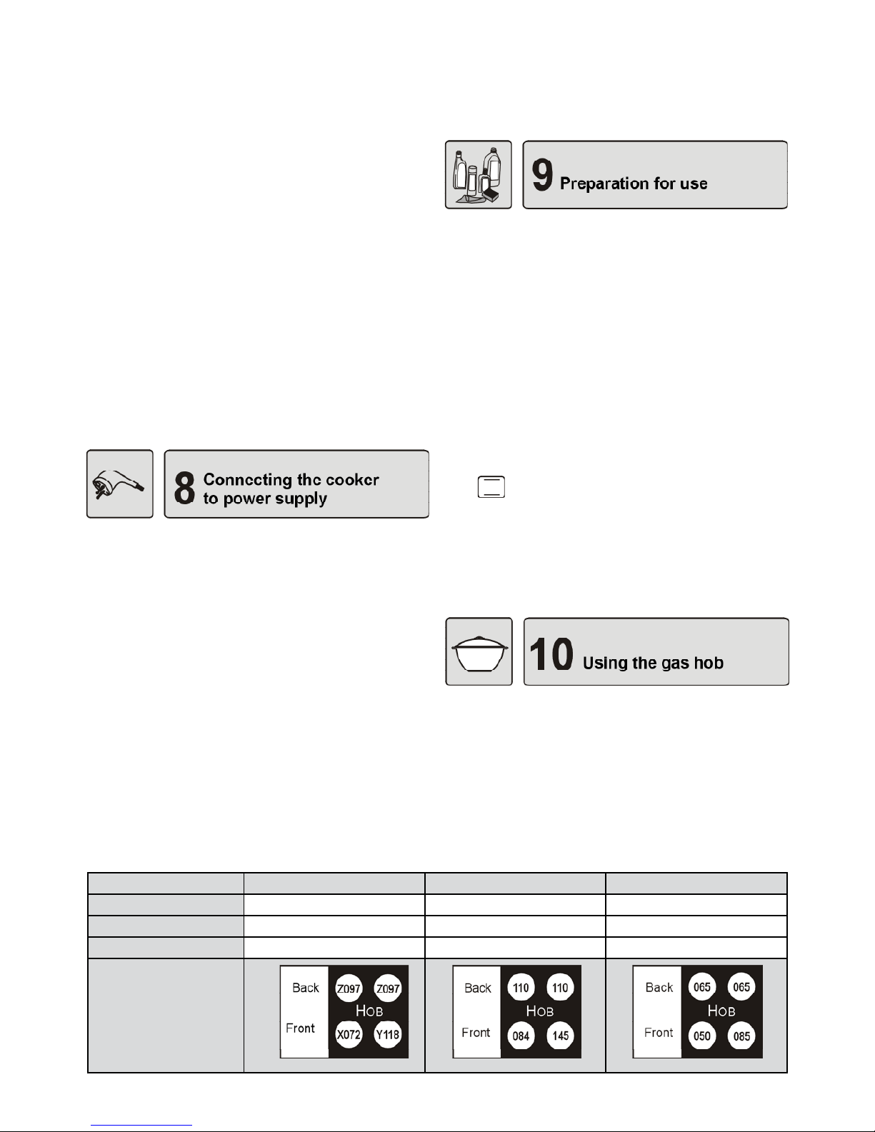
39
EN
turn the adjustment screw “A” (g. 7.4.1) and –
watch the ame; set the ame to such a size that
will prevent it from being extinguished by a slight
draught or during the operation of quickly turning
the knob from the full to the simmering position
of the ame and back;
the adjustment is correct when the core of the –
ame is cone-shaped in green and blue colour
and is ca. 2 – 4 mm tall
if there are perceptible changes of gas pressure –
in the gas supply system (change in the size of
ame at full ow), the simmering ame should be
set when pressure in the system is low to prevent the burner from extinguishing during normal
use,
upon adjusting the taps, put the knob back in its –
position and turn off the ame.
The amount of gas used with taps set to minimal gas
ow corresponds to ca. 25 % of use when the taps
are set to full ame.
8.1 The cooker is equipped with the power cord with
a plug and must be connected to a mains socket
properly tted with earth contact (g. 8.1.1).
8.2 If the power cord is not tted with a plug, the plug
must be connected to it. The cord must be tted
with a plug with a proper grounding prong. Before connecting to a power supply, ensure that:
– the voltage indicated on the nameplate matches
the mains voltage at the site where the appliance
is connected
– the performance of the power supply at the place
of connection is sufcient to meet the maximum
power requirements of the appliance, as specied
on the nameplate.
The mains socket should be easily accessi-•
Table 1 Burner nozzle specication
ble to the user.
Make sure that the power cord does not come •
into contact with hot parts of the cooker.
Wipe the enamelled and glass surfaces with a soft •
damp cloth.
Make sure that all parts of the burners are positio-•
ned correctly.
Remove the equipment and foil from the oven and •
clean it with warm water with added detergent.
If the appliance is equipped with an electronic ti-•
mer, set the current time after connecting the cooker to the electricity supply. Instructions for use
of the electronic timer are explained further in the
manual
Before the rst use, close the oven door and turn •
the oven on for ca. 30 minutes. The oven must be
empty when heated. Turn the oven control knob
to
and the temperature adjustment knob to
250°C. The smoke and smell produced during this
procedure are only slight, provided that the room is
well ventilated, e.g. by opening the windows. After
it has cooled down, clean the oven according to
instructions set forth in section “Cleaning and Maintenance”.
10.1 Gas burners (g. 10.1.1)
A – sparker
B – end of thermocouple (ame safety device)
10.2 Knobs
The gas ow in particular burners is opened and closed with the use of knobs tted on the gas taps. Before turning the burner on, make sure that the knob
2E-G20 20mbar 2E-G20 13mbar 3B/P-G30 30mbar
Small burner X072 084 050
Medium burner Z097 110 065
Large burner Y118 145 085
Arrangement of
burner nozzles

40
EN
you are about to turn corresponds to the burner which
is to be used. The burners and their corresponding
knobs are shown in g. 10.2.1.
10.3 Setting the ame
The ame should not lick around from the bottom of
a pan. The size of ame depends on the position of
the knob (g. 10.3.1, 10.3.2, 10.3.3).
0 – burner switched off (ow of gas shut off);
- large ame; - small ame (simmering)
10.4 Large ame (g. 10.3.2) should be used
until the liquid is brought to boiling after which the
ame should be turned down and further cooking
continued over a small ame
(g. 10.3.3). The
size of the ame should be adjusted only within
the range of small
and large ame: – (g.
10.4.1).
10.5 Lighting the burners
The cookers are equipped with a ame failure safety device which cuts off the gas ow to the burners
when the ame is extinguished, e.g. by overowing
food.
press the knob of the selected burner all the way –
in, turn it in the counter-clockwise direction and
hold until the burner has ignited (g. 10.5.1),
when the burner has ignited, keep the knob pu- –
shed in for ca. 5 seconds to allow the ame failure device to energise
release the knob and set the size of the ame –
If the ame has accidentally extinguished, close
the gas ow and wait for at least 1 minute before
retrying to reignite the burner.
10.6 Extinguishing the burners.
Turn the burner knob in the clockwise direction to its
“0” position.
10.7 Lighting the burners (cookers supplied
from an LPG cylinder)
Before lighting the rst burner, open the valve on the
LPG cylinder, and then light the burner in accordance
with the above described.
When cutting off the gas ow, prior to extinguishing
the last burner:
close the valve on the LPG cylinder, –
when the ame has gone out, close the tap of –
that burner.
When the cooker is not in use, the valve of the LPG
cylinder should be closed.
10.8 Cookware selection
Cookware base diameter should be 2-3 times •
greater than the diameter of the burner ring (g.
10.8.1). Cookware should not protrude outside the
gas hob grid and the ame should not lick around
from the bottom of a pan (g. 10.8.2).
Cookware should always be clean and dry as it will •
then conduct and retain heat well.
During cooking, the cookware should be covered •
with lids to prevent excess amounts of vapour from
accumulating in the kitchen.
Minimal cookware dimension:
for small burner – Ø 90 mm –
for medium burner – Ø 160 mm –
for large burner – Ø 200 mm –
11.1 Parts and accessories (g. 11.1.1)
[1], [2], [3], [4], [5] – guide levels
1 – upper heater
2 – grill heater
3 – lower heater
4 – oven lamp
5 – perforeted shield
6 – temperature sensor
11.2 Oven control knob (g. 11.2.1)
Oven control knob enables the user to select a function suitable for preparing a particular dish. The knob
can be rotated in both directions. Shown below are
functions applicable for oven.
Lower heater turned on
Heat is delivered by the lower heater located beneath the oor of the oven. This function allows for extra
heating the bottom surface of the dish. It is recommended to use this function during the last 10 – 15
minutes of baking.
Upper heater turned on
This heating method can be used for extra heating of
the top surface of the dish.
Lower heater and fan turned on
Both the lower heater and the fan are on. The vent
distributes the heat delivered by the lower heater.
Lower and upper heater turned on – conven-
tional baking
Both heaters deliver heat to the oven. Dishes should

41
EN
be placed on one level of the oven, preferably the
middle one. This kind of heating is ideal for cooking
cakes, meat, sh, bread, pizza, etc.
Traditional baking with heat evenly distri-
buted by the fan
The fan circulates hot air around the dish which is
being prepared in the oven. This function
requires temperatures lower than in traditional baking methods.
Traditional grilling
This faction is intended for grilling small size dishes
(steaks, kebabs, sausages, sh, toasts, krouts, etc.)
The dish should be placed on a baking tray or a roasting spit on the middle level of the oven.
The grilling time is assumed approximately 8 - 10 minutes per each centimeter of thickness.
Before starting to grill your dish, pre-heat the oven at
a maximum temperature. At half grilling time, turn the
dish upside down.
When grilling meat on a roasting-spit, place a drip
tray lled with ca. 0.5 l of water under the grilled dish
on a lower level of the oven.
Grilling with the fan
This function allows for grilling with heat evenly distributed throughout the oven.
Defrosting
With the vent turned on, the heat is distributed
evenly around the dish, thereby ensuring regular defrosting of frozen foods. This function is suitable for all types of frozen foods.
Frozen vegetables may be prepared straight
away without defrosting.
11.3 Temperature adjustment knob
Temperature adjustment knob (g. 11.3.1) enables to
adjust the temperature in the oven and maintain it at
the desired level.
The temperatures indicated on the knob correspond
to the temperatures in the oven (after the heat-up).
Adjusting the temperature – turn the knob right to
the desired position within the temperature rage of
50 – 250 °C.
After baking – turn the knob left and set it to zero
indicated by a symbol of a dot (•).
11.4 Indicator lights (panel 2.6.1)
Orange indicator light indicates• that the oven is
turned on. This indicator light turns on each time
when any of the oven function has been selected
and turns off after the oven has been switched off
by setting the oven control knob to “0” (off).
Red indicator light indicates• that the temperature
adjustment knob has been used. The light appears
when the temperature adjustment knob has been
set to a particular temperature and goes off when
the selected temperature has been reached in the
oven. When the oven is being used, the light will
turn on or off, thereby signalling that the heaters
have been automatically switched on to maintain
the temperature in the oven or switched off when
the desired temperature has been reached.
11.5 Electronic timer
Electronic timer enables you to control the oven using
an automatic and semi-automatic mode.
It is also possible to control the oven functions manually, without using the timer.
Electronic timers’ functions are set out in separate
instructions.
11.6 Oven light
For your comfort and safety, the oven has been tted
with a light bulb which lights up the inside of the oven
during its operation. The light turns on after any of
the available baking functions has been selected and
goes off after the oven has been switched off.
11.7Accessories
Standard accessories of the oven include one or
two baking trays (g. 11.7.1) and a baking grid (g.
11.7.2)
The baking grid is designed for placing baking tins
with dishes intended for baking or roasting. Certain
foods may be placed directly on the grid, e.g. meat,
sausages or sh. In such cases, a drip tray lled with
ca. 0.5 l of water must be placed underneath to collect the dripping fat. This will keep the oven clean.
11.8 Using the oven
1. Heat the oven and put the baking tin containing
the dish on a selected oven level (g. 11.8.1)
2. Select a baking function using the oven control
knob, e.g.
(g. 11.8.2).
3. Set the oven to the desired temperature (e.g.
200°C) using temperature adjustment knob (g.
11.8.3).
4. In cookers tted with electronic timers, the work of
the oven may be programmed by the user.
5. After baking, switch off the oven by turning the
oven control knob and the temperature adjustment knob to zero (off).

42
EN
Note!
1. When in operation, the appliance must not
be left unattended, as certain parts of the cooker may become very hot. Keep children well
away!
2. In ceramic-enamel ovens, dishes must not be
placed on the highest level [5].
11.9 Oven use
For baking cakes, traditional metal cake tins may •
be used as well as Teon, ceramic, glass or aluminium foil cake trays (g. 11.9.1). The most universal are metal tins due to their various shapes
and application. Before rst use, all metal cake tins
must be baked in a well-heated oven to remove
the smell.
Fill the tins 2/3 full of dough, leaving enough place •
for it to rise.
Ceramic, glass, enamelled steel and cast-iron co-•
okware with heat-resistant handles may be used
(g. 11.9.2) for roasting meat.
Before putting a cake into the oven, the oven must •
be pre-heated.
During baking the dough should be heated even-•
ly. This can be done by choosing the
or
function.
If the dough outer layer is too brown, next time pla-•
ce the cake tin on a lower level in the oven, set a
lower temperature, and allow the dough to bake
longer.
If the dough bottom is too brown, next time place •
the cake tin on a higher level in the oven and set a
lower temperature.
If you place dough in the overheated oven, the cake •
may be doughy or fail to rise. If the dough stays in
the oven too long, it may dry out or the outer layer
may become too brown.
When selecting the baking time and temperature •
take into account the weight and consistency of the
pastry.
Place utensils with food at any level of the oven, •
depending on the used function.
Observation and experience help in choosing the •
best level, temperature and oven function for a par-
ticular dish.
It is recommended to start the rst baking with me-•
dium temperatures, according to the recipe, and
then adjust the temperature to suit the needs the
next time. If baked in lower temperatures, the cake
becomes evenly brown all over its surface.
In order to check whether the cake is baked, it sho-•
uld be pierced with a thin wooden rod a few minutes before switching off the oven. The cake is ready
if it does not stick to the rod. After baking the cake
should be kept in the oven for about 5 minutes.
The following are recommended when using the •
oven:
do not use the oven for storage purposes, –
cake tins, casseroles and dishes for roasting –
meat should be placed on the gridiron (centrally) and not on the tray (g. 11.9.3 and 11.9.4),
when selecting cooking parameters, take the –
type of cookware to be used into consideration;
dishes have different levels of heat conduction
depending on their material, wall thickness and
colour.
Stewing meat is best when done using the func-
tion
, especially for lean meat. Other type of
meat, including minced meat and poultry, may be
roasted using the function
.
Pizza
You can make your own pizza or a frozen pizza in the
oven. It is recommended that you rst preheat the
oven using the function
, and then cook the pizza
at temperature about 2000C after choosing the func-
tion
. With these functions, the heat is distributed
mainly from the bottom. Put the dish on one level of
the oven, preferably on level [2].
Frozen pizza may be put immediately into a preheated oven and cooked as described above.
In case of heavy steam when baking very moist food, it is recommended to put a lid on the
dish and remove it towards the end of cooking to
brown the dish.
Important !
Below in tables the approximate cooking times
for various foods have been summarized. These
are only suggestions and in practice these values may vary. We recommend making several
tries for a particular dish and noting down the
optimum time and temperature.

43
EN
Meat Amount [kg] Temperature [0C] Time [hour:min]
Beef 1 220 - 250 2:00 - 2:30
Pork 1 210 - 225 1:30 - 2:00
Veal 1 210 - 225 1:45 - 2:00
Mutton 1 210 - 225 1:30 - 2:00
Game (hare) 2 oven preheated 210 - 230 1:00 - 1:50
Chicken 1 225 - 250 0:45 - 1:00
Fish 1 210 - 225 0:45 - 1:00
Meat dishes Table 3
Roasting and stewing meat with the fan
Table 4
Meat Amount [kg] Temperature [0C] Time [hour:min]
Chicken 1 180 0:50 - 1:00
Game (hare) 1 - 1,5 160 2:00 - 2:20
Veal 1 160 1:40 - 2:20
Pork 1 175 1:50 - 2:00
Beef 1 160 2:00 - 2:30
Goose, duck - 175
1)
1)
individually adjust time to weight
Cake Temperature [0C] Baking time [hour:min]
Round cake 160 - 175 1:15 - 1:20
Yeast cake 175 - 190 0:50 - 1:00
Sponge-cake 170 - 180 0:30 - 0:40
Short crust oven preheated 210 - 220 0:10 - 0:25
Plaited bun 190 - 200 0:30 - 0:40
Strudel (apple) 220 0:40 - 0;50
Fruit cake 200 - 210 0:25 - 0:50
Streusel cakes 200 - 220 0;20 - 0;30
Cakes Table 2
Backing cakes with the fan
Table 5
Cake Temperature [0C] Baking time [hour:min]
Meringues 100 1:00 - 1:10
Round cake 160 1:05 - 1:10
Tea cake 160 1:00 - 1:10
Yeast cake 175 0:40 - 0:45
Streusel cakes 175 0:20 - 0:30
Fruit cake 175 0:40 - 0;55
Sponge-cake 160 0:30 - 0:40

44
EN
Grilling Table 6
Dish Time [min] on one side Time [min] on the other side
Chicken steak and cutlets 8 - 10 6 - 10
Joint of pork 10 - 12 6 - 8
Sausages 8 - 10 6 - 8
Kebabs 7 - 8 5 - 6
Beef steak 6 - 7 5 - 6
Joint of beef 10 - 12 10 - 12
Veal cutlet 6 - 8 6 - 8
Veal steak 6 - 7 5 - 6
Chicken - a half 10 - 15 (on the inside) 10 - 12 (on the outside)
Fillet 6 - 7 4 - 5
Krouts 2 - 3 1 - 2
Toast 3 - 5 2 - 3
12.1 General notes
Electronic digital programmer is a modern unit controlling operation of the oven. The programmer indicates current time with the accuracy to 1 minute.
After each completed program, it generates a sound
signal and automatically switches the oven off.
The programmer enables execution of the following
functions:
setting the current time, –
programming the time of oven operation, –
programming the time of switching the oven off, –
programming the time of operation and time of –
switching the oven off in 24-hour cycle,
setting the timer, –
It is possible to control operation of the oven •
not using the programmer - after pressing
button.
If the automatic control program is complete, •
and the dish requires further roasting, then
you may reprogram operation of the oven or
press the manual operation button
and
control further roasting.
The programmer may be used as a timer, with •
the timer running independently of the program.
Programming consists in pressing the button of the
selected function (e.g.
) and setting the desired
time using „+” setting button. You can adjust the time
using „-” setting button.
Pressing „+” or „-” setting buttons for a short time causes change of time by one minute, and depressing
them for a longer time - activating the quick scroll
mode.
Programming:
press and release the button of the selected –
function,
during the time up to 5 seconds after releasing of –
the function key, set the required time using „+”
and possibly „-” setting buttons; if during these
5s programming is not started - the called function will disappear,
after approx. 5s from the end of programming, –
the programmer will display the current time and
starts to execute the program.
The following graphic symbols may appear on the
programmer display:
„AUTO” - Automatic operation symbol
Continuous lighting means that the program is
being executed. Pulsing informs about the end
of the program (the programmer is waiting for
re-programming or switching over to the manual
operation cycle).
- Locking symbol
The oven may be protected from change of settings or accidental activation, especially by chil-
dren.
- Oven operation signal
Continuous lighting signals operation of the oven
(providing that it is switched on).
- Timer signal
Continuous lighting means that the timer is set.

45
EN
A - Automatic operation;
B - Hours;
C - Oven operation symbol;
D - Minutes;
E - Timer symbol;
F - Lock symbol;
1 - timer button;
2 - operating time button;
3 - operation end button;
4 - manual operation button;
5 - time „decreasing” setting button;
6 - time „increasing” setting button
When the cooker has been connected to the •
power supply mains, pulsating messages
„0.00” and „AUTO” appear on the programmer display.
The rst action which should be taken upon •
connection of the cooker to power supply is
set-ting the current time.
The current time should be set also after de-•
cay of voltage in the mains lasting longer
than 5s.
Accuracy of the programmer readings de-•
pends on parameters of the supply mains,
therefore it should be adjusted periodically
by comparing it with another timer.
12.2 Setting the current time
simultaneously depress –
and buttons,
using „+” (and possibly „-”) setting button set the –
required time e.g. 11.38,
when the time has been set, release all buttons. –
During the time of approx. 5s from releasing of the
buttons, the time will be stored. The time set i.e.
11.38 will appear on the display. When the current
time is set, the oven will run in the manual mode.
12.3 Switching off the sound signal
After completion of each program, the oven will be •
switched off automatically, and the sound signal
will be activated.
After certain time, the sound signal will be switched •
off automatically.
The user may switch off the sound signal earlier by •
depressing any button of the programmer.
12.4 Timer
The timer is designed for sound signalling when the
time set elapses. You can use it when performing
short time cooking operations (e.g. boiling eggs).
The timer does not switch the oven off.
when the time is being measured out by the ti-•
mer, you can program operation of the oven,
the timer can be set during execution of any pro-•
gram.
Setting the timer:
press –
button,
using: „+” and possibly „-” setting buttons set the –
desired time (e.g. 3 minutes).
After approx. 5 s the current time will appear on the
display and
indicator will be illuminated. When
the time set (i.e. 3 minutes) elapses, the sound signal will be activated. The signal can be disabled by
pressing any button.
Deleting the timer setting:
press –
button,
press „-” setting button and hold it till the messa- –
ge „0.00” appears on the display,
NOTE !
In order to check how much time is left till the
end of the timer operation, press
button. Depressing of this button does not stop measuring
of time.
12.5 Programming the oven operating time
When the time of operation has been programmed
and the oven function selected, the oven will be
switched on immediately.
Programming the time of operation:
press –
button,
using „+” and possibly „-” setting buttons set the –
required time of operation e.g. 35 minutes
When the time set elapses, the following occurs:
the oven is switched off automatically, –
sound signal is activated, –
the symbol „ – AUTO” pulsates on the programmer
display and the symbol
is off.
If further operation of the oven is needed (e.g. in order to nish baking of a cake), you may reprogram
the time, or press the manual operation button
and control further operation of the oven.
When the operation is over, move the functional knob

46
EN
of the oven to zero position.
12.6 Programming the time of switching off
When the time of switching off is programmed and
the oven function selected, the oven is switched on
immediately.
Programming the time of switching off:
press –
button,
using „+” and possibly „-” setting buttons set the –
time of switching off the oven e.g. 11.50.
When the time set elapses:
the oven is switched off automatically, –
sound signal is activated, –
„ – AUTO” pulsates on the programmer display.
If the dish is not baked sufciently, you may reprogram the time of operation as in the point above, or
set the time of switching the oven off, or depress the
manual operation button
and control further ope-
ration of the oven.
When the operation is over, move the functional knob
of the oven to zero position.
12.7 Automatic control
Operation in automatic mode consists in programming the time of operation and time of switching off
the oven an in points 12.5 and 12.6.
The oven will be switched on automatically at the
time dened, and when the time set elapses it will
be switched off automatically.
Example - Roasting beef:
- it is 13.00
- roasting time 2 hours
- roasting temperature 2200C
- the dish to be prepared for 17.00
Put the meat into an oven-pan, add approx. 10 •
spoonfuls of water and cover it with a lid. Then
put the pan into the oven, place it on the mesh on
a chosen level, and close door of the oven.
Using the functional knob choose the position •
, and using the thermoregulator knob set
the temperature of 2200C.
Press •
button and using „+” and possibly „-”
setting buttons determine the roasting time i.e. 2
hours.
Press •
button and using „+” and possibly „-”
setting buttons set the time of 17.00 (time when
roasting is complete).
Operation of the oven has be programmed and it will
be carried out automatically.
At 15.00 the oven will be switched on automatically
and it will run for 2 hours. At 17.00 the appliance will
be switched off automatically which is signalled by
activation of the sound signal. At this time „AUTO”
pulsates and
is off.
If the dish is not roasted sufciently, you may re-program operation of the oven, or press the manual ope-
ration button
and control further roasting.
COMMENT !
Pressing 1.
button during operation of the
oven will enable you to display the programmed time of switching off.
When 2.
button is depressed, the programmed time of the oven operation is displayed.
If the oven has already started to run, the time
which is left to complete the program will appear.
12.8 Changing settings
Settings can be changed within the period up to 5s
from commencement of programming or after deletion of the program.
Changing the time of operation:
press –
button,
using „+” and „-” buttons you can set a new –
time.
Changing the time of switching off:
press –
button,
using „+” and „-” buttons you can set a new –
time.
12.9 Deleting settings
Deleting the time of operation:
press –
button,
press „-” button and hold it till the message „0.00” –
appears on the display.
Changing the time of switching off:
press –
button,
press „-” button and hold it till the message „0.00” –
appears on the display.
When the program is deleted, operation of the oven
can be re-programmed.
12.10 Manual control
If during execution of the program the user in-•
tends to start manual operation, the program
should be deleted and
button should be
pressed.

47
EN
Pressing of this • button will disable functions
of the programmer. Then the oven is operated
only using the oven functional knob and temperature regulator knob.
In the manual control mode you can use the ti-•
mer.
NOTE !
Pressing
button will result in switching over
to the manual operation mode. It means that heaters of the oven are switched on for undetermined time; in order to switch them off, set the
functional knob of the oven to „0” position.
12.11 Locking function
This function enables protection from tampering of
children. It means that when this function is chosen,
the child may select any program on the programmer
but the program will not be changed.
Before any protecting actions are started, the programmer should be in the manual mode.
Locking the oven:
simultaneously press –
and buttons and
hold them in this position for approx. 8 seconds,
till the word „ON” appears on the display,
press „+” button, –
the word „ – OFF” appears on the display and the
lock symbol
is illuminated,
after approx. 5s the current time appears on the –
display near the lock symbol
; the oven is loc-
ked.
Unlocking:
the programmer should be in the manual mode, –
simultaneously press –
and buttons and
hold them in this position for approx. 8 seconds,
till the word „OFF” appears on the display,
press „+” button, –
the word „ – ON” appears on the display and the
lock symbol
is off,
after approx. 5s the current time will appear aga- –
in on the display; the oven in unlocked.
12.12 Night blackout
At the time between 22.00 and 5.59 the programmer
automatically reduces intensity of the display ligh-
ting.
During this time, the display is illuminated intensively
only when:
the timer is measuring out the time, –
currently a program is executed, –
any button has been pressed. –
NOTE !
Before proceeding with cleaning, disconnect the
cooker from the power supply.
13.1 General Tips
The cooker should be kept clean. The following •
may not be used for cleaning: abrasive powder cleaners, metal scouring pads, aggressive chemical
agents or sharp objects.
Stainless steel elements, knobs, dials and the con-•
trol panel should be cleaned with mild liquid detergents containing no abrasive agents.
For enamelled parts use a soft brush or sponge •
moistened with warm water containing mild detergents, avoiding excessive water. For heavily soiled
surfaces use kitchen-cleaning agents.
Do not clean glass surfaces using any abrasive •
agents or metal items, as they may scratch the
surface and cause the glass to break.
The hob surface around burners should always be •
clean as dirt deteriorates the combustion of gas.
When cleaning the hob do not allow water to get
beneath the hob.
Burners and igniters must be kept clean and dry to •
ensure their trouble-free operation.
Take the dirty grids off the gas hob, soak them in •
warm water with detergent and then wash and dry
them.
Immediately after use, trays and tins for baking •
and roasting should be soaked in warm water with
detergent and then washed and wiped dry.
Oven door gasket should be kept clean.•
13.2 Cleaning the burners
NOTE !
Clean the burners, sparkers each time they become spilled and also periodically remove blooms
or dirt.
Elements of the burners (g. 13.2.1)
1 – lid 4 – nozzle
2 – ring 5 – sparker
3 – body 6 – thermocouple
To clean the burners remove the lid and the ring •
of the burners, put them in warm soapy water for
some time and then wash each part of the burner
separately.
Clean the burner elements using a sponge or a •
soft brush and remove dirt from burner ports with a

48
EN
clip 1 onto catch 2 of hinge bow 3 (g. 13.4.2),
grasp the door with both hands, turn it by about –
45
0
(in the closing direction) and pull the hinges
out of their seats (g. 13.4.3).
NOTE !
1. As the hinge’s bow is very tight, remove the
doors carefully to avoid hurting your ngers.
2. It is forbidden to clean the oven with the use of
steam pressure cleaners.
If the light bowl is dirty, unscrew the bowl, and wash •
and dry it thoroughly (13.4.4).
Enamelled ovens are coated with ceramic ena-•
mel.
For enamel surfaces use kitchen-cleaning agents.•
For removing difcult baking stains, special oven •
cleaning agents are recommended. However, these agents are caustic and therefore should be used
in small quantities and with utmost care. Please
follow the manufacturer’s instructions carefully.
NOTE !
Before proceeding with the troubleshooting, disconnect the cooker from the power supply to
avoid being electrocuted.
In the warranty period all repairs except for the •
ones specied below should be carried out by the
authorised Servicing Point.
If there are some disturbances during the use of •
the appliance, follow the guidelines below to check
if you can repair the defect yourself.
Problem Solution
Igniters fail to ignite or not always ignite
the gas
Check to make sure the cooker is connected to the electrical mains. –
Clean and dry the igniters and burner components. –
Check to make sure the burner caps and heads are placed correctly. –
Press on the burner cap and rub it against the head by turning right –
and left (g. 14.1.1).
Rub the igniter electrode with the use of hard brush or smooth le (g. –
14.1.2).
Flame dies after releasing the knob
Your cooker is equipped with a ame failure safety device
Where the ignition device is built in the knob set the – knob to large a-
me
, press the knob and when the gas has ignited keep it pressed
all the way in for another few seconds.
14.1.1 14.1.2
steel wire. After cleaning check if the burner ports
are clear.
To avoid permanent stains, rings should be washed •
each time after they become soiled.
The hob surface around the burner should be kept •
clean at all times. Dirt may clog the nozzle, which
results in reduced gas ow or stoppage.
The nozzle should be cleaned with a small paint-•
brush dipped in a solvent.
Dry all the elements of the burners carefully as wet •
elements may not light or cause the gas to combust improperly. Assemble clean and dry burners
carrying out the disassembling steps in the reverse
order, taking care not to damage the sparkers.
13.3 Cleaning the gas hob
For the enamelled hob surface use special deter-•
gents for cleaning cookers (g. 13.3.1)
13.4 Cleaning the oven
Before cleaning the oven, ensure it is completely •
cool. Hot heaters may cause burns.
Preferably clean the bottom of the oven after each •
use to avoid re-heating of food and fat remnants.
When cleaning the bottom of the oven do not pour •
water on it. Take care not to ood the oven burner.
During cleaning the upper wall of the oven pay at-•
tention to electric heaters, temperature sensor and
the oven lamp; do not change position of sensor
setting.
To facilitate cleaning of the oven you can remove •
the oven door.
Removing the oven door:
open the door completely, –
lock the hinges (g. 13.4.1) at each side by tting –

49
EN
Problem Solution
Gas burners fail to ignite Check to make sure the rubber hose supplying gas from the gas cylin- –
der is not squeezed.
Check to make sure the gas main valve is open. –
Check to make sure the gas cylinder is not empty. –
In case a new cooker has been installed or the gas cylinder has been –
replaced with a new one, then it is necessary to repeat the ignition
procedure until the gas reaches the burner.
Check to make sure the nozzle or burner ame holes are not clogged –
or ooded. If so, un-clog the nozzle hole using a pin or needle. Clean
the burner ame holes with the use of brush, and then dry all compo-
nents.
While igniting one of the burners all the
hob burner igniters spark
It is normal
When pressing the selected knob (with a built-in ignition device) or the
ignition button sparks are re-leased at all the burners .
After setting the knob to simmering ame
position
- the ame dies or is too high
Avoid draughts in the kitchen, –
Call the tter to adjust simmering ame position –
.
Flame is unstable Check to make sure that the burner components are clean, dry and –
placed correctly.
Parts made of stainless steel (inox) develop stains that cannot be removed with the
use of standard cleaners
Stainless steel surfaces should be cleaned – each time they get soiled
and only with the use of special stainless steel cleaner.
Smoke coming out of the oven
Open the windows to air the kitchen, –
When the oven cools down, clean its interior and especially the spit. –
Use the drip tray when grilling foods. –
Oven light does not function
1. Check to make sure the cooker is connected to the electrical mains.
2. The bulb is burnt or not screwed all the way in.
Disconnect the cooker from the electrical mains before xing the
fault.
Unscrew glass bowl 1 from light socket 2 and screw bulb 3 all the –
way in or replace the bulb with a new one (bulb type: E14 230V 25W,
resistant to temperature of 300
0
C).

50
EN
“0.00” pulsates on the display Drop or temporary breakdown of voltage. Take the plug out of the electric
socket, wait for a while, then plug in the cord and set the current time.
Damaged power lead In order to avoid hazards, damaged power lead should be exchanged
at the manufacturer’s or by a specialist servicing point, or by a qualied
person.
Cooking results are not what you expected
The cooking parameters given in the instruction manual should be treated as guidance only. In practice, these parameters are dependable on
the weight and consistency of food, cooking tray level, etc. Therefore, we
recommend making a few trials for your favourite foods and then writing
down the optimal time and temperature.
NOTE !
If after completing the above steps the appliance is still inoperative contact your local service centre
KGE 3416 ZB Plus
KGE 3416 ZX Plus
KGE 3416 ZN Plus
Energy efciency class
1)
A
Energy consumption – traditional baking [kWh]
2)
0,79
Energy consumption – roasting with forced air circulation [kWh]
2)
0,88
Oven capacity [l] 55
Oven chamber size Medium
Time needed to heat standard load [min.] 45
Surface area of max. baking tray [cm
2]
1080
This labelling means that the device, upon end of its
life cycle, should not be disposed of together with
other household waste.
The user is responsible for having the device collected by appropriate entities responsible for disposal of
used electrical and electronic devices.
Appropriate disposal of used electrical and electronic
devices allows to avoid hazards to the humans and
the environment connected with inappropriate storage and processing of such devices.
This device is labelled, in accordance with Council Directive 2002/96/EC,
with a symbol of a crossed garbage
container.
1)
from A (more efcient) to G (less efcient)
2)
for standard load
TECHNICAL PARAMETERS OF THE OVEN

ul. ¯migrodzka 143, 51-130 WROC£AW
e-mail: kontakt@fagormastercook.pl
infolinia 0703 103 131
www.mastercook.pl
FagorMastercook S.A.
FAGOR MASTERCOOK
A F A G O R G R O U P C O M P A N Y
10.2010
C601051I7
 Loading...