


EN USER MANUAL
PL INSTRUKCJA INSTALACJI I OBSŁUGI
Cooking hob
Płyta grzejna
GCF32SI

PL
20
EN
02
As part of our commitment to constantly improve our products, we reserve the right to alter
any technical, functional and/or aesthetic features as part of their ongoing development.
Warning:
Before installing and using your appliance, please read this Guide to
Installation and Use carefully, as this will allow you to familiarise yourself with it
faster.

3
1/ NOTICES TO THE USER
• Safety Instructions . . . . . . . . . . . . . . . . . . . . . . . . . . . . . . . . . . . . . . . . . . . . . . . 04
• Caring for the environment . . . . . . . . . . . . . . . . . . . . . . . . . . . . . . . . . . . . . . . . 05
• Description of your appliance . . . . . . . . . . . . . . . . . . . . . . . . . . . . . . . . . . . . . 06
2 / INSTALLING YOUR APPLIANCE
• Choice of location . . . . . . . . . . . . . . . . . . . . . . . . . . . . . . . . . . . . . . . . . . . . . . . 07
• Before installation . . . . . . . . . . . . . . . . . . . . . . . . . . . . . . . . . . . . . . . . . . . . . . . 07
• Fitting tips . . . . . . . . . . . . . . . . . . . . . . . . . . . . . . . . . . . . . . . . . . . . . . . . . . . . . . 08
• Electric connection . . . . . . . . . . . . . . . . . . . . . . . . . . . . . . . . . . . . . . . . . . . . . . 08
• Gas connection . . . . . . . . . . . . . . . . . . . . . . . . . . . . . . . . . . . . . . . . . . . . . . . . . 09
• Changing the gas supply . . . . . . . . . . . . . . . . . . . . . . . . . . . . . . . . . . . . . . . . . 11
3/ USING YOUR APPLIANCE
• Description of your hob top . . . . . . . . . . . . . . . . . . . . . . . . . . . . . . . . . . . . . . . 14
• Switching on the gas burners . . . . . . . . . . . . . . . . . . . . . . . . . . . . . . . . . . . . . 14
• Cookware suitable for gas burners . . . . . . . . . . . . . . . . . . . . . . . . . . . . . . . . . 15
4/ DAILY CARE OF YOUR APPLIANCE
• Maintaining your appliance . . . . . . . . . . . . . . . . . . . . . . . . . . . . . . . . . . . . . . . . 16
5/ SPECIAL MESSAGES, INCIDENTS
• During use . . . . . . . . . . . . . . . . . . . . . . . . . . . . . . . . . . . . . . . . . . . . . . . . . . . . . 17
6/ COOKING CHART
• Gas cooking guide . . . . . . . . . . . . . . . . . . . . . . . . . . . . . . . . . . . . . . . . . . . . . . 18
7/ AFTER-SALES SERVICE . . . . . . . . . . . . . . . . . . . . . . . . . . . . . . . . . . . . . . . . . . . .
• Service calls . . . . . . . . . . . . . . . . . . . . . . . . . . . . . . . . . . . . . . . . . . . . . . . . . . . . 19
ENTABLE OF CONTENTS
4
SAFETY INSTRUCTIONS
— We have designed this cooking hob for use
by private individuals in their homes.
— This appliance must be installed in
compliance with currently applicable
regulations and used only in a well-ventilated
location. Consult this guide before installing
and using your appliance.
— All cooking should take place under your
surveillance.
— Ces tables de cuisson destinées
exclusivement à la cuisson des boissons et
denrées alimentaires ne contiennent aucun
composant à base d’amiante.
— This appliance is not connected to a
combustion by-product disposal system. It
must be installed and connected in
compliance with all applicable laws. Special
attention should be given to applicable
regulations concerning ventilation.
— Do not store
CLEANING
products or
FLAMMABLE
products (aerosol cans or
pressurised containers, as well as papers,
cookbooks, etc.) in the cabinet underneath
your cooking hob.
— If you use a drawer located under the hob,
we recommend that you avoid using it to
store items that are heat sensitive (plastic,
papers, aerosol cans, etc.).
— Your hob should be disconnected from
power and fuel supplies (electricity and gas)
before any repairs.
— When you connect the power cables of any
electrical appliances plugged in close to the
hob, ensure that they are not in contact with
the cooking zones.
— As a safety measure, do not forget to close
the overall supply tap for gas distributed by
pipe or the tap of the tank for butane or
propane gas after use.
— The CE mark is affixed to these hobs.
— Installation should only be performed by
installers and qualified technicians.
— L’installation est réservée aux installateurs
et techniciens qualifiés.
— Before installation, ensure that the local
distribution conditions (gas type and
pressure) and the settings of the appliance
are compatible.
— This hob is compliant with standard
EN 60335-2-6 relating to the heating of
cabinets and the Class 3 standard with
regard to installation (as per standard EN 301-1).
- In order to easily locate the reference
information for your appliance, we
recommend that you note these data on the
“After-Sales Service Department and
Customer Relation”.
•
Warning
The required settings for the hob are
written on a sticker located in the plastic
bag, as well as on the packaging.
In order to easily locate the reference
information for your appliance, we
recommend that you note it on the “AfterSales Service Department and Customer
Relations” page (this page also explains
where to find this information on your
appliance).
- This appliance is not intended for use by
persons (including children) with impaired
physical, sensory or mental capacities, or by
inexperienced or untrained persons, except
if they have been instructed in its operation
by a person responsible for their safety.
Children should be watched to ensure that
they do not play with the appliance.
This unit is not intended to be used with an
external timer or a separate remote control
system.
If a crack appears in the surface of the
glass disconnect your appliance
immediately to prevent a risk of electric
shock. Contact the After-Sales Service
Department.
Attention
Keep this user guide with your
appliance. If the appliance is ever sold or
transferred to another person, ensure that
the new owner receives the user guide.
Please become familiar with these
recommendations before installing and
using your appliance. They were written for
your safety and the safety of others.
EN
1 / NOTICES TO THE USER
5
— This appliance’s packing materials are
recyclable. Recycle them and play a role in
protecting the environment by depositing
them in local authority containers provided
for this purpose.
Your appliance also contains
various recyclable materials. It is
therefore marked with this logo to
indicate that, in European Union
countries, used appliances must
not be mixed with other waste.
Appliance recycling organised by
your manufacturer will thus be
carried out in optimum conditions, in
accordance with European directive
2002/96/CE relating to electrical and
electronic equipment waste. Contact your
local council or your retailer to find out the
drop-off points for used appliances that are
nearest to your home.
We thank you for your help in protecting the
environment.
•
CARING FOR THE ENVIRONMENT
EN1/ NOTICES TO THE USER

6
•
DESCRIPTION OF THE HOB
A
B
Burner cover
Burner head
Injector
C
D
Spark igniter
Thermocouple
Knob
E
F
G
H
Gasket
Valve
Tip
This Guide to Installation and Use is valid for several models. There may be minor
differences in details or fittings between your appliance and the descriptions provided.
Grill support pan
D
C
B
A
E
F
H
G
Burner
EN
1 / NOTICES TO THE USER
7
•
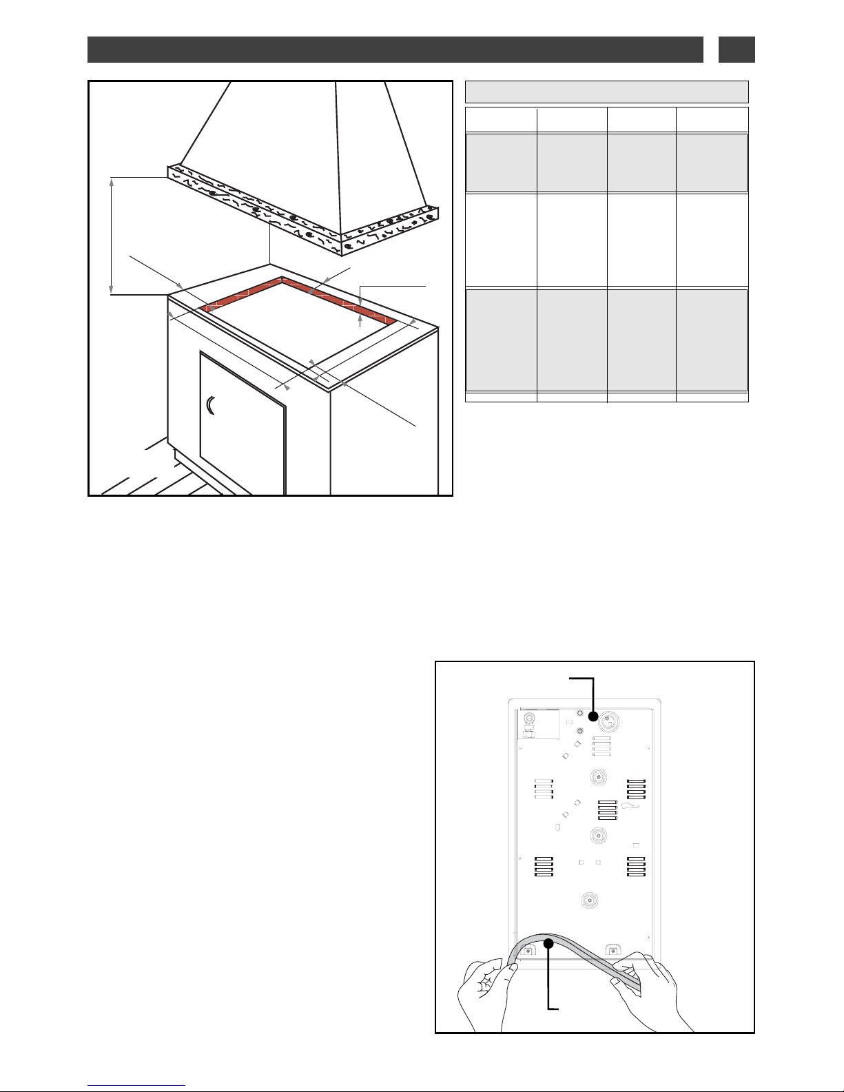
CHOICE OF LOCATION
Your appliance shoud be flush mounted in the
surface of a support cabinet that is a minimum of
3 cm thick, made of a material that resists heat or
that is covered with such a material.
If a horizontal divider wall is positioned under the
hob, it should be placed between 10 cm and 15 cm
away from the top of the work surface. Never store
aerosol cans or pressurised containers in any
compartment that may exist under the hob (see
chapter “Safety instructions”).
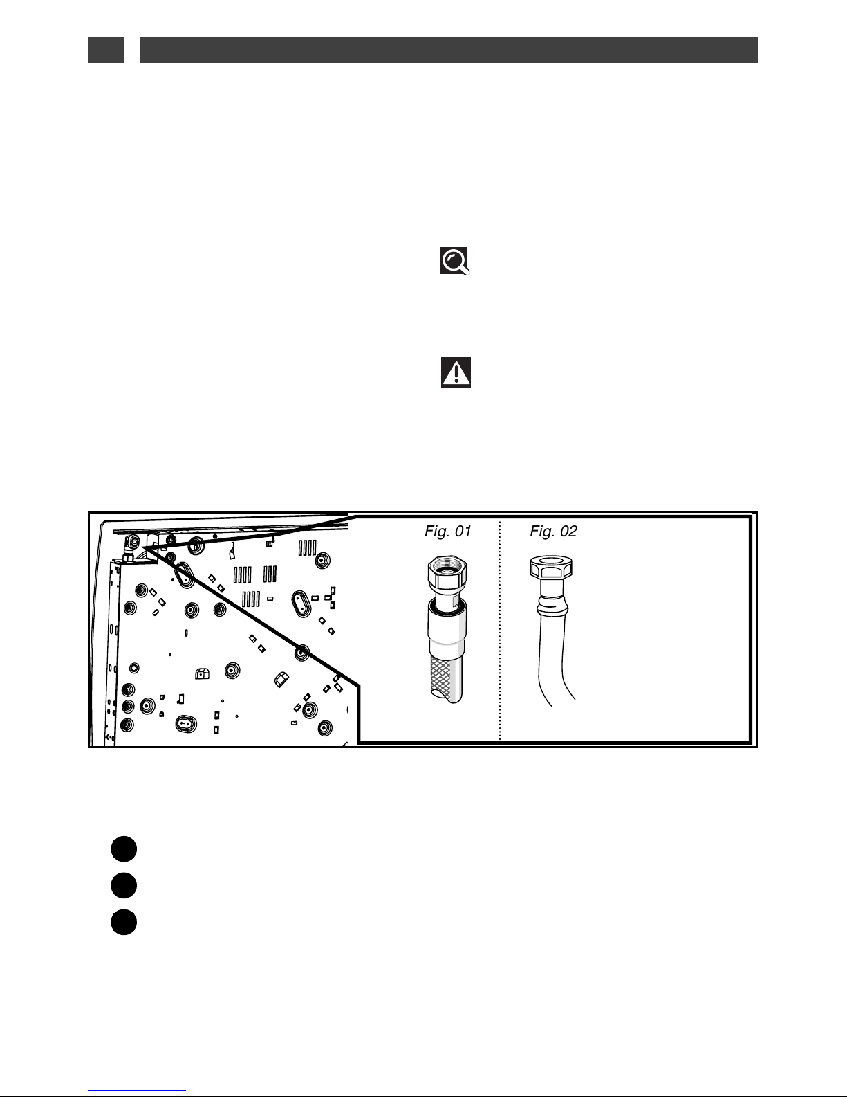
BEFORE INSTALLATION
of your applicance and to ensure leaktightness
between the drawer unit and the work surface,
make sure that you glue the seal provided in the
plastic bag
(Fig. 02)
.
— Remove the pan supports, the burner covers and
burner heads; noting their positions.
— Turn the hob over and carefully place it on top of
the opening in the cabinet so as not to damage the
knobs and spark plugs.
— Glue the foam seal, supplied with the appliance,
to the outside edge of the frame. This seal ensures
leaktightness between the glass and the work
surface.
— Place your hob in the opening of the support unit,
carefully centering it in the cut-out.
— Reposition the pan supports, burner covers and
burner heads.
— Connect the hob’s power cable to your kitchen’s
electricity supply (see section “Electric
connection”).
— Connect your appliance to the gas supply (see
section “Gas connection”).
•
48 cm mini
3 cm mini
30 cm mini
26,5 cm
30 cm mini
5,8 cm mini
70 cm mini
Fig. 01
Fig. 02
Housing
Joint
APPAREIL
Découpe
meuble
standard
Dimensions
hors tout
au-dessus
du plan de
travail
Dimensions
hors tout
au-dessous
du plan de
travail
Largeur
26,5 cm
31 cm
26 cm
Profondeur
49 cm
51 cm
47 cm
Epaisseur
suivant
meuble
5 cm
5,1 cm
EN2 / INSTALLING YOUR APPLIANCE

8
— Place your hob in the opening of the
support cabinet, carefully pulling the table
towards you.
— Reposition the burner heads, burner
covers and pan supports on the hob.
Connect your hob to the gas supply (See
“Gas Connection” chapter) and to the power
supply (See “Electrical Connection” chapter).
— If you wish, you can immobilise the hob
using the four mounting brackets delivered
with their screws
(Fig. 02)
to attach them to
the four corners of the housing. You must
use the holes provided for this purpose,
according to the diagram above
(Fig. 01)
.
— Stop screwing when the mounting bracket
starts to become deformed.
Do not use a screwdriver.
•
FITTING TIPS
EN
2 / INSTALLING YOUR APPLIANCE
Fig. 02
Mounting bracket
Screw
Mounting holes
A
Cabinet
•
ELECTRIC CONNECTION
Your hob must be connected to the 220-240 V
~
single phase grid via a standardised CEI 60083
2-pole + ground electrical outlet plug or an allpole cut-off device, in compliance with the
current regulations.
The plug of the electrical outlet must be
accessible after installation.
Warning
The safety wire (green/yellow) is
connected to the ground terminal of
the appliance and must be connected to the
ground terminal of the installation The fuse
in your set-up must be 10 amperes. If the
power cable is damaged, it must be replaced
by a cable or a special kit available from the
manufacturer or its After-Sales Service
Department.
Tip
Using a gas cooking appliance results in
the generation of heat and humidity in the
location where it is installed. Make sure that
your kitchen is well-ventilated: keep natural
ventilation openings in your home clear or
install a mechanical ventilation device
(mechanical ventilation hood). Intensive,
prolonged use of the appliance may require
additional ventilation; you can, for example,
open a window or provide more effective
ventilation by increasing the power of the
mechanical ventilation system, if you have one.
(A minimum air flow of 2 m
3
/hr per kW of gas
power is required).
For example : 30 cm, 2 gas burners +
Total power: 1.5 + 3.1 = 4.6 kW
4.6 kW x 2 = 9.2 m
3
/hr minimum
flow.
CROSS-SECTION OF CABLE TO BE USED
H05V2V2F -T90 cable
Ref. After-sales
service: 77x9060
Cross-section of
conductors in mm
2
Fuse
220-240 V~- 50 Hz
3 conductors
including
1 ground
1
10 A
A
Fig. 01
Underside view
of the housing
A
9
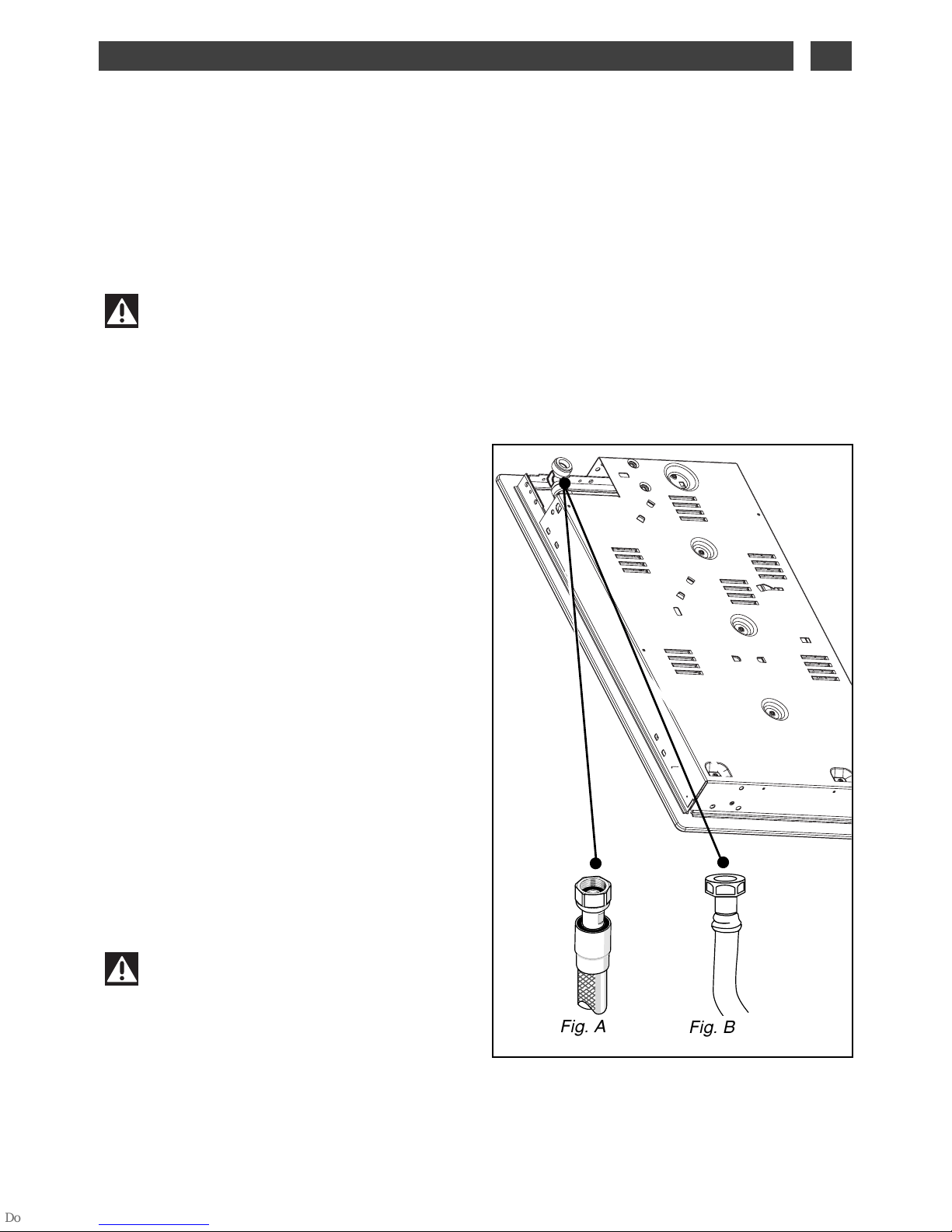
The gas connection must be installed in
compliance with applicable regulations in the
country of installation.
•
Natural gas supplied by pipe,
For your safety, you must choose from the
three following connection options:
— Connection with a rigid pipe
made from
copper and with screw-on mechanical
connectors (G1/2 gas standard mark). Make
the connection directly to the end of the
elbow fitted on the appliance.
— Connection with a wavy metal hose
(stainless steel)
with screw-on mechanical
connectors (compliant with the NF D 36-121
standard) whose service life is unlimited
(Fig. A).
— Connection with a reinforced rubber
hose
with screw-on mechanical
connectors
(compliant with the NF D 36-103 standard)
whose service life is 10 years
(Fig. B).
Warning
When connecting your hob’s gas
supply, if you have to change the direction
of the elbow fitted on the appliance:
① Change the sealing washer.
Screw on the elbow’s nut, being careful not
to exceed a torque of 17 N.m.
GAS CONNECTION
• Preliminary comments
If your hob is installed above an oven or if proximity to other heating elements poses a threat of
overheating the connection, you must insulate the cable in a rigid pipe.
If a hose or soft pipe (in the case of butane gas) is used, it should not come into contact with a
moving part of the cabinet, nor should it pass through a location that may become blocked.
•
Warning
All soft pipes and hoses whose service life is limited must have a maximum length of
two meters and must be accessible along their entire length. They must be replaced before
the end of their service life (marked on the pipe). Regardless of the means of connection
chosen, ensure that the connection is leaktight, after installation, with soapy water.
EN2 / INSTALLING YOUR APPLIANCE
Fig. A
Fig. B
10
•
Gas supplied by tank or
cylinder (butane/propane)
For your safety, you must choose from the
three following connection options:
— Connection with a rigid pipe
made from
copper and with screw-on mechanical
connectors (G1/2 gas standard mark). Make
the connection directly to the end of the
elbow fitted on the appliance.
— Connection with a wavy metal hose
(stainless steel)
with screw-on mechanical
connectors (compliant with the NF D 36-125
standard) whose service life is unlimited
(Fig. 01).
— Connection with a reinforced rubber
hose
with screw-on mechanical
connectors
(compliant with the NF D 36-112 standard)
whose service life is 10 years
(Fig. 02).
A
B
Seal (not provided)
Adaptor (not provided)
Clamp (not provided)
C
In an existing system, a soft pipe fitted with
clamps (compliant with the XP D 36-110
standard) whose service life is five years may
be used. It is necessary in this case to use an
adaptor without forgetting to fit a sealing
washer between the adaptor and the hob’s
elbow
(Fig. 03).
Tip
You can obtain the adaptor and the sealing
washer from your After-Sales Service
Department.
Warning
Screw on the adaptor with a torque
not exceeding 25 N.m.
Fig. 01
Fig. 02
EN
2 / INSTALLING YOUR APPLIANCE

11
CHANGING THE GAS SUPPLY
Warning
Your appliance is sold pre-set for
natural gas.
The injectors required for adapting it to
butane/propane can be found in the plastic
bag containing this guide.
Each time you change the gas supply, you
must complete the following:
— Adapt the gas connection
— Change the injectors
— Adjust the hob connections.
•
Adapt the gas connection
:
Refer to the
“Gas Connection”
section.
•
Change the injectors, proceeding as
follows:
—
Remove the pan supports, heads and
covers from all burners.
—
Using the wrench provided, unscrew the
injectors located under each crucible and
remove them
(Fig. 01).
—
Replace with the corresponding gas
injectors, in compliance with the positioning of
the injectors and the table of gas properties at
the end of this section:
—
First screw them in manually until the
injector locks into place.
—
Apply the wrench to the injector as far as it
will go.
—
Draw a line on the burner plate using a
pencil at the place indicated
(Fig. 02).
—
Turn the wrench clockwise until the line
appears on the other side
(Fig. 03).
Warning
Exceeding this limit may damage the
product.
-
Reposition the burner heads, burner covers
and pan supports on the hob.
•
Tip
Each time you change the gas supply,
tick the box corresponding to the new gas
level on the label found in the plastic bag.
Refer to the corresponding “Gas Connection”
section.
Fig. 02
Line
Line
Wrench
Wrench
Fig. 01
Wrench
Injector
Crucible
EN2 / INSTALLING YOUR APPLIANCE
12
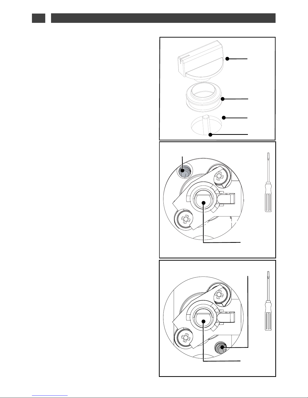
•
Adjust the hob connections: these are
located underneath the knobs
(Fig. 04)
.
—
Proceed one tap at a time.
—
Remove the knobs and the gaskets by
pulling them up.
- Switching from natural gas to
butane/propane (depending on model)
-
Using a small flat-head screwdriver, screw in
the brass burner-power screws (yellow) all the
way,
(Fig. 05)
screwing them in a clockwise
direction.
-
Replace the gaskets and the knobs, paying
careful attention to their direction and
ensuring that the knobs are pushed in all the
way.
- Switching from butane/propane to natural
gas (depending on model)
-
Unscrew the brass (yellow) burner power
screws
(Fig. 06)
, using a small flat-head
screwdriver, turn twice counterclockwise.
-
Replace the knob.
-
Light the burner in maximum heat mode,
then turn down to reduced heat mode.
-
Remove the knob again, then turn the
burner power screw clockwise until it reaches
the lowest possible setting that does not
extinguish the flame.
-
Replace the gasket and knob.
-
Make several attempts to change from the
maximum flow rate to the minimum: the flame
should not go out ; if it does, unscrew the
burner-power screw so as to obtain good
flame retention during these position
switches.
-
Reposition the burner heads, burner covers
and pan supports on the hob.
Fig. 05
Tap axis
Burner power
adjustment screw
Fig. 06
Tap axis
Burner power
adjustment screw
Knob
Base
Gasket
Tap
Fig. 04
EN
2 / INSTALLING YOUR APPLIANCE
 Loading...