

Page 1

NTP100 -SERIES
NETWORK TIME PROTOCOL SERVER
Masterclock, Inc. Tel: 636-724-3666 Fax: 636-724-3776
2484 W Clay St,, St Charles MO 63301 © Masterclock, Inc. Dec-04 Printed in USA
USER MANUAL
Page 2

DISCLAIMER
The information contained in this document is subject to change without notice. Masterclock, Inc. (hereinafter MC) makes
no warranty of any kind with regard to this material, including, but not limited to, the implied warranties of merchantability
and fitness for a particular purpose. MC shall not be liable for errors contained here in or for incidental or consequential
damages in connection with the furnishing, performance, or use of this material.
See important limited warranty information at the end of this document.
ADVISORY NOTICE
CONCERNING GPS SATELLITE SYSTEM AND THE NTP100-GPS
Depending on many factors beyond the control of MC, the signals that are received from the GPS satellites are subject to
interference, fading, satellite failure and other influences that could cause the NTP100-GPS to provide erroneous time
and/or date information and, under some conditions, could prevent it from providing time/date information.
It is the responsibility of the user to determine the adequacy and suitability of this device for the intended use.
CONCERNING TIME CODE INPUT AND THE NTP100-TC
Depending on many factors beyond the control of MC, the signals that are received from the Time Code Input Source are
subject to interference, noise, loading effects and other influences such as time code format that could cause the
NTP100-TC to provide erroneous time and/or date information and, under some conditions, could prevent it from providing
time/date information.
It is the responsibility of the user to determine the adequacy and suitability of this device for the intended use.
Page 3

Table Of Contents
Introduction .........................................................................................................................................................................1
Introducing the NTP100 Family....................................................................................................................................1
UTC/Greenwich Mean Time.........................................................................................................................................1
NTP (Network Time Protocol) ......................................................................................................................................1
GPS Satellites (model NTP100-GPS only)....................................................................................................................2
Installation...........................................................................................................................................................................2
Operating Environment....................................................................................................................................................2
GPS Antenna and Cable (model NTP100-GPS only) .........................................................................................................2
Antenna Location.........................................................................................................................................................2
Pre-Installation Checklist .................................................................................................................................................3
Network Security/Topology Considerations..................................................................................................................3
Quick Start Information....................................................................................................................................................3
Initial I/O Connections and Operation...........................................................................................................................3
Start-Up and GPS Satellite Acquisition (model NTP100-GPS)......................................................................................6
Start-Up and Time Code Acquisition (model NTP100-TC)............................................................................................6
Input Impedance.......................................................................................................................................................6
Input Level...............................................................................................................................................................6
Time Code Input Select ............................................................................................................................................6
Front-Panel Behavior .......................................................................................................................................................7
Major Feature Overview...................................................................................................................................................7
DHCP/BOOTP Auto-Configuration..............................................................................................................................7
NTP Broadcasts............................................................................................................................................................8
Configuration.......................................................................................................................................................................8
Battery Backed RTC and Configuration ............................................................................................................................8
Reset Factory-Default Configuration ................................................................................................................................8
Default Password.............................................................................................................................................................8
Configuration Methods.....................................................................................................................................................8
WinDiscovery..............................................................................................................................................................9
Potential Communication Problems ..........................................................................................................................9
Using WinDiscovery................................................................................................................................................9
Properties............................................................................................................................................................... 10
Network Settings....................................................................................................................................................11
Device Settings.......................................................................................................................................................11
Set Password..........................................................................................................................................................14
Set Time/Date.........................................................................................................................................................15
Status..................................................................................................................................................................... 18
Telnet Terminal Configuration.................................................................................................................................... 19
Set Device Name....................................................................................................................................................20
Set IP Configuration ...............................................................................................................................................20
Set/Reset Password.................................................................................................................................................21
Set Display Intensity...............................................................................................................................................21
Set NTP Stratum Levels..........................................................................................................................................21
Set NTP Server Port................................................................................................................................................22
Set NTP Broadcast Options.....................................................................................................................................22
Configure Telnet Interface...................................................................................................................................... 22
Set Reference Identifier .......................................................................................................................................... 23
Set RTC Backup/Time Dissemination Options........................................................................................................23
Set Time/Date Options............................................................................................................................................23
Exiting Telnet ......................................................................................................................................................... 24
RS-232 Terminal Configuration (specific to models NTP100-GPS and NTP100-OSC only) ........................................25
NTP Client Information...................................................................................................................................................... 25
Dimension 4............................................................................................................................................................... 25
TimeSync...................................................................................................................................................................25
NTP100 – Rev 1.0.1 Dec-04 © Masterclock®, Inc.
Page 4

XNTP ........................................................................................................................................................................25
Win32Time (W32Time) .............................................................................................................................................25
Disclaimer..................................................................................................................................................................26
Troubleshooting Tips.........................................................................................................................................................26
Problem: You have lost your password.......................................................................................................................27
Problem: The UTC date/time is incorrect and the unit does not retain configuration settings when powered up. ........... 27
Time Code Decoding Issues ...........................................................................................................................................27
Problem: The UTC time (&/or date ) is incorrect.........................................................................................................28
Specifications ....................................................................................................................................................................29
Communications – Protocol............................................................................................................................................ 29
Communications – I/O................................................................................................................................................... 29
Time Code Input – (model –TC).....................................................................................................................................29
Power Requirements ......................................................................................................................................................29
Physical .........................................................................................................................................................................29
Pre-Amplified Antenna (required for model NTP100-GPS only) ................................................................................29
Operating/Storage Temperature & Humidity...............................................................................................................30
LIMITED WARRANTY .......................................................................................................................................................31
Exclusions.......................................................................................................................................................................31
Warranty Limitations.........................................................................................................................................................31
Exclusive Remedies ..........................................................................................................................................................31
NTP100 – Rev 1.0.1 Dec-04 © Masterclock®, Inc.
Page 5

Introduction
Introducing the NTP100 Family
The NTP100 is a family of high-precision Ethernet network time servers, utilizing the Network Time Protocol (NTP).
The NTP100 family of NTP time servers, consists of the following NTP100 members:
MODEL Primary Reference Secondary Reference
NTP100-GPS
NTP100-TC
NTP100-OSC
External GPS satellite signal
• internal GPS receiver
• requires external GPS antenna
External Time Code signal using
• internal time code decoder
• requires external SMPTE 30/25/24 fps or
IRIG-B/B(1) time code source
Internal TCXO (Temperature Compensated Crystal
Oscillator) , & RTC (real-time clock) reference.
Each NTP100 device can operate on a local area network (LAN) or act as an enterprise-wide source for traceably
accurate time and date distribution, depending upon your network configuration.
Each NTP100 device includes the WinDiscovery configuration & management software, as well as a Telnet interface
for configuration and maintenance. Other common features include:
• Internal clock with temperature controlled oscillator (TCXO), retains time during loss of power (all models) ,GPS
satellite signal (model –GPS), or time code signal (model –TC).
• Supports NTP broadcast and/or query mode.
• Fully configurable network settings, including DHCP/BOOTP or Static IP addressing support
• Security features include password protection of configuration, encrypted communication, and the ability to disable
telnet management access
• Adjustable time display brightness
• Status display to remotely monitor status and behavior
• Selectable Stratum Identification levels
UTC/Greenwich Mean Time
Internal TCXO & RTC
Internal TCXO & RTC
None
UTC is a time standard which is the basis for the worldwide system of civil time. This time scale is kept by time laboratories
around the world, including the U.S. Naval Observatory, and is determined using highly precise atomic clocks. The UTC
scale is coordinated in Paris by the International Bureau of Weights and Measures (BIPM).
UTC runs at the rate of the atomic clocks, but when the difference between this atomic time and one based on the Earth
approaches one second, a one second adjustment (a "leap second") is made in UTC.
UTC is the local time at the prime reference meridian at Greenwich, England. At a given location on the planet, local time
can be displaced (referenced to UTC) by -11 to +12 hours. North and South America are from -3 to -11 hours delayed; most
of Europe and Africa and all of Asia and Australia are advanced by +1 to +12 hours. Because the NTP time distribution
standard operates with UTC-reference time only, time zone and/or daylight savings (summer) time are not used.
UTC is sometimes colloquially referred to as "Greenwich Mean Time" (abbreviated GMT).
NTP (Network Time Protocol)
NTP is an open-standard time synchronization protocol designed for precision synchronization and maintenance of
time/date on computers and other devices attached to TCP/IP networks. NTP itself is transported with the UDP/IP
(User Datagram Protocol), and is usually served on port 123. NTP time/date is UTC-referenced, as the protocol has no
provisions for representing time zones or daylight savings (summer) time.
NTP100 – Rev 1.0.1 Dec-04
1
© Masterclock®, Inc.
Page 6

A wealth of useful NTP information and resources can be found at http://www.ntp.org
GPS Satellites (model NTP100-GPS only)
The GPS satellites are operated and maintained by the U.S. Department of Defense and allow for the precise determination of
local time and location at any point on (or above) the Earth. This is accomplished via the transmission of very accurate
timing information from a series of satellites that provide coverage of the entire planet.
The NTP100-GPS derives the precision UTC time that it serves from the GPS satellite network using an internal GPS
receiver and requires the connection of a pre-amplified GPS antenna.
Installation
Operating Environment
The NTP100 is not water or moisture proof and is designed for indoor use only. Treat it as you would any other
delicate electronic device and do not expose it to water, excessive heat or physical abuse. Please see the
“Specifications” section.
GPS Antenna and Cable (model NTP100-GPS only)
The NTP100-GPS requires a pre-amplified antenna. It provides 5 VDC via the center pin of the coaxial for remote power.
[WARNING: Attaching a passive (non pre-amplified) antenna to the NTP100 could destroy the GPS receiver module.
This is a major repair cost which is not covered by warranty.]
The unit is tested and shipped with the appropriate cable for the antenna that was ordered. Should you require a longer
antenna cable we recommend that you contact MC so that a properly matched cable and antenna can be supplied.
Although changing the GPS antenna or coaxial cable is not technically difficult, you are on your own should you decide to
make such changes. We do not warrant or support operation with any hardware not installed or supplied by us.
The coaxial cable should not be crushed, crimped or bent at a sharp angle nor should it be strained by pulling. Any damage
to the cable could result in the NTP100-GPS not functioning properly. If the cable is to be coiled for storage, the coil
diameter should be at least 6”.
Antenna Location
Depending on the type of building where the NTP100-GPS is located and obstructions that may block reception of signals
from the GPS satellites, the antenna may have to be located where it has an unobstructed view of the sky. In some cases this
can be accomplished by placing the antenna adjacent to a window. In most cases it will require mounting the antenna outside
of the building or on a roof. In the worse case, the basic requirement for assured system operation is that the antenna module
have a clear and unobstructed view of the sky for initial satellite acquisition and lock. It is possible that the system will
operate indoors and under other obstructions however this can only be determined empirically; it is not guaranteed.
If a longer cable is required, cables of various lengths (up to 500 feet) with pre-amplified antennas are available from
Masterclock, Inc.
[Note: bringing the NTP100-GPS up for the first time with an indoor antenna may prevent or significantly increase the
time to first fix.]
NTP100 – Rev 1.0.1 Dec-04
2
© Masterclock®, Inc.
Page 7

Pre-Installation Checklist
Before installing an NTP100 one should be prepared with the following basic configuration information that the device will
require. It may be necessary to obtain some or all of this information from a network administrator in your organization.
• IP address
• Gateway (router)
• Net mask
• Domain name servers
- or –
• Confirm availability of DHCP/BOOTP server (for dynamic networking configuration)
All Masterclock, Inc. network appliances can be provided with a verbose name. The name is not used for any internal
purpose by the NTP100 and is arbitrary. It may be useful for organizing and managing devices once installed at a facility.
By default, device names are the product name abbreviation followed by the device’s ethernet address (MAC address).
Customers may wish to designate names relating to their own organizational requirements. It is recommended that a robust
naming scheme be developed before devices are installed to different locations within an organization.
Network Security/Topology Considerations
Networks separated by physical routers will often block UDP broadcasts preventing WinDiscovery from locating
devices on a remote network. Under such circumstances, WinDiscovery must be operated from a computer
within the remote network or routers separating the networks must be configured to pass through (both directions)
UDP broadcasts on port 6163. Consult your network administrator for additional information.
Personal computer firewall applications, such as ZoneAlarmTM or BlackICETM, may also prevent WinDiscovery
from operating correctly. Configure the firewall to allow bi-direction UDP traffic on port 6163.
Quick Start Information
Initial I/O Connections and Operation
Refer to the table below and begin your installation at the step indicated for your NTP100 model number.
MODEL Front Panel View Rear Panel View Begin at
NTP100- GPS
NTP100-TC
NTP100-OSC
STEP 1
STEP 3
STEP 4
NTP100 – Rev 1.0.1 Dec-04
3
© Masterclock®, Inc.
Page 8
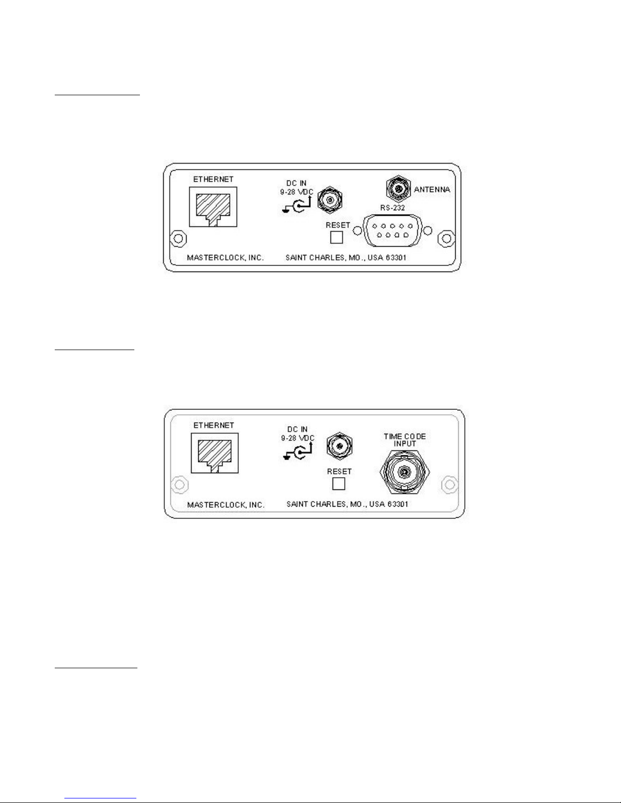
Model NTP100-GPS
1. Locate the antenna in a suitable area so that the top of the antenna module has a clear view of the sky. Do not move it
until after the NTP100-GPS has achieved satellite lock (explained below).
2. Connect the antenna coax to the gold SMA connector on the rear of the unit (labeled Antenna).
NTP100-GPS Rear View
Continue at step 4
Model NTP100-TC
3. Connect the time code signal cable to BNC female connector on the rear of the unit (labeled Time Code Input), and then
to a valid UTC referenced time code signal source.
[Note: The NTP100-TC auto-detects and decodes the date encoded incoming time code signal as UTC referenced time and
treats the incoming time code signal as UTC referenced. Non-date encoded SMPTE or IRIG-B/B(1)
Continue at step 4
All NTP100 Models
4. Connect an RJ-45 10-baseT ethernet cable to the female RJ-45 connector on the rear of the unit (labeled Ethernet), and
then to a hub or switch on your ethernet network.
NTP100 – Rev 1.0.1 Dec-04
NTP100-TC Rear View
4
© Masterclock®, Inc.
Page 9
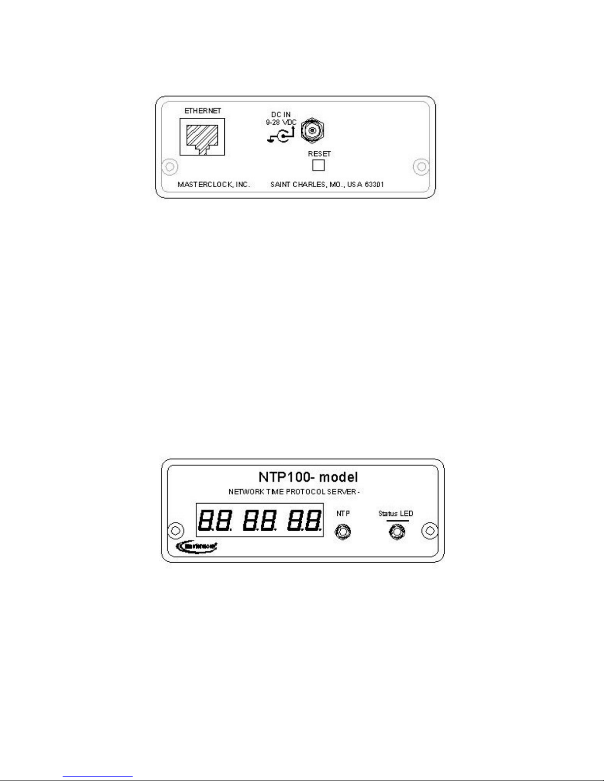
NTP100
-
Rear View , Common to all models
-
NTP100
-
Front Panel, Common to all models
5. Apply power by inserting the power supply module into an appropriate AC power source and the power connector into
the male Switchcraft-style locking power socket on the rear of the unit (labeled DC IN).
6. If desired the unit can be operated from a nominal 12 VDC battery (9-18 VDC range). Observe voltage polarity as
indicated on the rear panel (the center pin is positive +VDC, and is labeled 9 -28VDC).
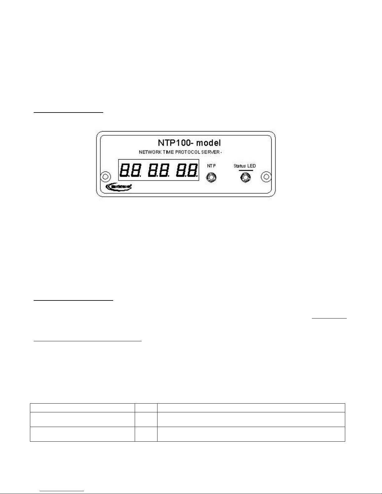
7. When power is first applied the initial sequence of the front panel LED is:
• amber and green LEDs on briefly, with time display showing 88:88:88
• all LEDs extinguish briefly
• amber (NTP) LED out, green (Status) LED steady on
• green (Status) LED begins twice per second blink, with time display incrementing the seconds digit once per second
(indicating locked to internal TCXO oscillator , and acquiring lock to an external source, if applicable).
• Green (Status) LED begins to blink once per second and time display increments the seconds digit once per second
when synchronized to an external reference source, if applicable.
[Note: when configured to obtain network configuration through DHCP, the display may hesitate on startup
while DHCP is resolved.]
At this time the NTP100 can be communicated with over the local network using the WinDiscovery application.
WinDiscovery can find and identify the NTP100 through the exchange of broadcast messages even when TCP/IP
networking parameters are not configured on the same network.
Once the NTP100 has a valid network configuration it can also be accessed via Telnet by computers in the same
logical network.
NTP100 – Rev 1.0.1 Dec-04
5
© Masterclock®, Inc.
Page 10

In situations where providing basic network configuration via WinDiscovery application is not practical, the
NTP100-GPS and NTP100-OSC can also be configured through an RS232 terminal interface. To use this feature,
connect an RS232 terminal (or PC serial port) to the DB-9 connector on the rear of the chassis with a straightthrough 9-pin cable. Once connected, press ENTER once to display the login/menu screen. Note this serial port
is not available in the model NTP100-TC.
Start-Up and GPS Satellite Acquisition (model NTP100-GPS)
When the NTP100-GPS is initially powered up, after having been shipped to a new location, the time to first fix (time the
unit takes to acquire satellites and extract correct time) could be up to 25 minutes although it is typically 5 - 15 minutes.
Factors such as atmospheric conditions, type of antenna, antenna location, and antenna cable length will affect the time to
first fix.
The NTP100-GPS’s navigation module is connected to a backup battery that maintains startup data when the unit is powered
down. If, when starting up, the location, time and number of satellites that the unit can receive has not changed significantly
since last power down then the unit will start up much faster.
Start-Up and Time Code Acquisition (model NTP100-TC)
When the NTP100-TC is initially powered up, after having been shipped to a new location, the time to first fix (time the unit
takes to detect, acquire, decode, gain adjust time code and extract correct time) could be up to 90 seconds although it is
typically 30 seconds or less. Factors such as the time code input signal level, time code signal type, time code cable length
and type, and system noise, will affect the time to first fix.
Input Impedance
The input impedance for the Masterclock TC time code decoder circuit is considered to be relatively high , typically
>100kOhm. This high input impedance allows for connecting multiple Masterclock TCR load devices in parallel without
loading and/or distorting the time code input signal.
Input Level
The input level is controlled via an automatic gain control circuit. The NTP100-TC firmware will automatically determine
the appropriate gain control setting for your incoming time code dB level.
The NTP100-TC cannot adjust for time code signal levels outside the range of -15 and +20dB.
The NTP100-TC requires up to 30 seconds to complete automatic gain control when decoding SMPTE or IRIG-B/B1. When
proper gain control has been achieved the incoming time code type and raw time code should be read and displayed on the
status screen in WinDiscovery, and the front panel status LED on the card will blink once per second.
Time Code Input Select
The NTP100-TC will automatically detect which format of time code is being provided upon initial power up with a valid
time code source, or if the time code input is varied. No user -programmable hardware or software adjustments are
necessary.
The NTP100-TC contains a time code decoder circuit which is designed to autodetect and decode time code information
along with date information from the following date encoded time code formats:
• SMPTE (30/25/25 fps) to Leitch Date Encoding Standard,
• IRIG-B pulse width coded (unmodulated) DC, to IEEE 1344 standard,
• IRIG-B(1) 1 kHz Amplitude Modulated, IEEE 1344 standard
Note: The time code input and date information is required and expected to be UTC. Time zone and/or Daylight Saving
Offset is not supported.
NTP100 – Rev 1.0.1 Dec-04
6
© Masterclock®, Inc.
Page 11
In addition, the NTP100-TC has a special provision to support non-date encoded SMPTE or IRIG-B/B(1) time code. The
NTP100
-
Front Panel, Common to all models
NTP100-TC contains a feature to set/overwrite the date or year manually by writing this information to the battery backed
real-time clock. When selected, this allows the user to either ignore the date/year information from the time code signal, or to
provide a date/year for SMPTE (date) or IRIG-B/B(1) (year) time code formats without this information in the time code
signal.
Front-Panel Behavior
The 6 digit LED time display shows the current time (referenced to UTC) available to the NTP100.
The green LED displays synchronization status with the internal time reference. When the LED is blinking at a
twice per second rate it indicates that the NTP100 is not synchronized with an external reference such as GPS or
time code. Once synchronized to the external reference, the green LED will blink at a once per second rate.
The amber LED lights briefly when an NTP request is serviced. This is provided as a general indication of when
and how frequently NTP requests are being processed.
Major Feature Overview
The features discussed in this section can be configured in several ways - the WinDiscovery software application provided
with your NTP100, or a terminal-style interface accessible via RS-232 and Telnet. Consult the section entitled Configuration
for details on how to adjust settings through the aforementioned mediums.
DHCP/BOOTP Auto-Configuration
DHCP (Dynamic Host Configuration Protocol) is a mechanism for automating the configuration of networked devices that
use TCP/IP. When DHCP is enabled, DHCP configuration acquisition will overwrite any manual configuration items. A
precursor to DHCP is BOOTP. The NTP100 can obtain configuration from a BOOTP server when no DHCP server is
present. Factory default: DHCP enabled.
The following RFC2132-defined optional configuration items are, when available, used by the NTP100 for configuration
purposes:
Option No. Comments
Router 3 The first IP address provided will be used for router/gateway
configuration.
Domain Name Server 6 Up to two server IP addresses may be specified. NTP100 will treat
addresses as primary and secondary DNS servers.
NTP100 – Rev 1.0.1 Dec-04
7
© Masterclock®, Inc.
Page 12

[WARNING: An NTP100 will not function properly if configured to use DHCP services when no DHCP server is present on
the network.]
NTP Broadcasts
The NTP100 supports the broadcasting of NTP packets. This feature is useful in situation where network administration may
wish to avoid the network traffic created by a large number of hosts making periodic NTP requests, or in situations where
such periodic requests end up synchronized is such a manner as to exceed the NTP100’s ability to reply.
Note that some firewalls and routers will not forward UDP broadcasts by default. Security configurations may need to be
adjusted to allow the UDP broadcast packets to pass on the configured port.
Configuration
The NTP100 maintains an internal configuration that defines a number of parameters regarding the unit’s operation.
The internal configuration is maintained even when power is off.
Battery Backed RTC and Configuration
The NTP100 maintains its internal configuration and settings in battery backed memory located on the RTC chip. The
battery supplies power to the TCXO 32kHz oscillator and RTC when the unit is powered off. This allows the internal
configuration to be maintained and the time and date to increment, when power is off. Under normal operating condition, the
memory devices maintaining the RTC data and configuration settings is powered by the external DC power supply and does
not rely on the battery for data retention.
The battery type is a ‘replaceable’ lithium coin cell battery .
Note: If the NTP100 does not retain its configuration, or its Date/Time settings (this may be indicated by the front panel time
display counting up from ‘zero’) the battery will likely need replacement. The battery size differs between models. See the
“Specifications” section for details on the recommended battery replacement.
Reset Factory-Default Configuration
In some situations (such as a lost password) it may be necessary to return the NTP100 to its factory default
configuration. A recessed button labeled “RESET”, located on the back of the NTP100 unit, performs this function. To
reset configuration to factory default
1) remove power from the NTP100,
2) depress and hold the reset button, and
3) apply power to NTP100 and continue holding the reset button down for five seconds.
Default Password
The factory-default password for an NTP100 is: public
Configuration Methods
Basic operation of the NTP100 is configured via the WinDiscovery software supplied with the unit, or via Telnet (or the
RS-232 interface for the model(s) NTP100-GPS & NTP100-OSC). Only one configuration method should be used at a
time.
NTP100 – Rev 1.0.1 Dec-04
8
© Masterclock®, Inc.
Page 13
WinDiscovery
The WinDiscovery (WD) program is a Windows OS based program supplied with the NTP100. WinDiscovery is supported
under Windows 98se/Me/NT , and 2000/XP operating systems. To install the WinDiscovery program on your
server/workstation/PC, complete the following steps:
1. Insert the software distribution diskette that shipped with your NTP100.
2. Run the ‘setup.exe’ application from the diskette.
3. By default, the setup utility will suggest installing files to C:\Program Files\WinDiscovery. (Another path may be
selected if desired.)
4. Press the Unzip button to unpack the files to the specified location.
5. Optional: create a shortcut to the ‘windiscovery.exe’ application in your Start Menu or on the Desktop.
Potential Communication Problems
Networks separated by physical routers will often block UDP broadcasts preventing WinDiscovery from locating
devices on a remote network. Under such circumstances, WinDiscovery must be operated from a computer within the
remote network or routers separating the networks must be configured to pass through (both directions) UDP traffic
(including broadcasts) on port 6163.
Personal computer firewall applications, such as ZoneAlarm©, may also prevent WinDiscovery from operating
correctly. Configure the firewall to allow bi-direction UDP traffic on port 6163 or temporarily disable the firewall
while using the WinDiscovery application.
Using WinDiscovery
Open the WD program by clicking the shortcut on your desktop (or other fashion dictated by your installation). Only
one user should be using WD at a time, and other methods should not be used to manage the NTP100 while using WD.
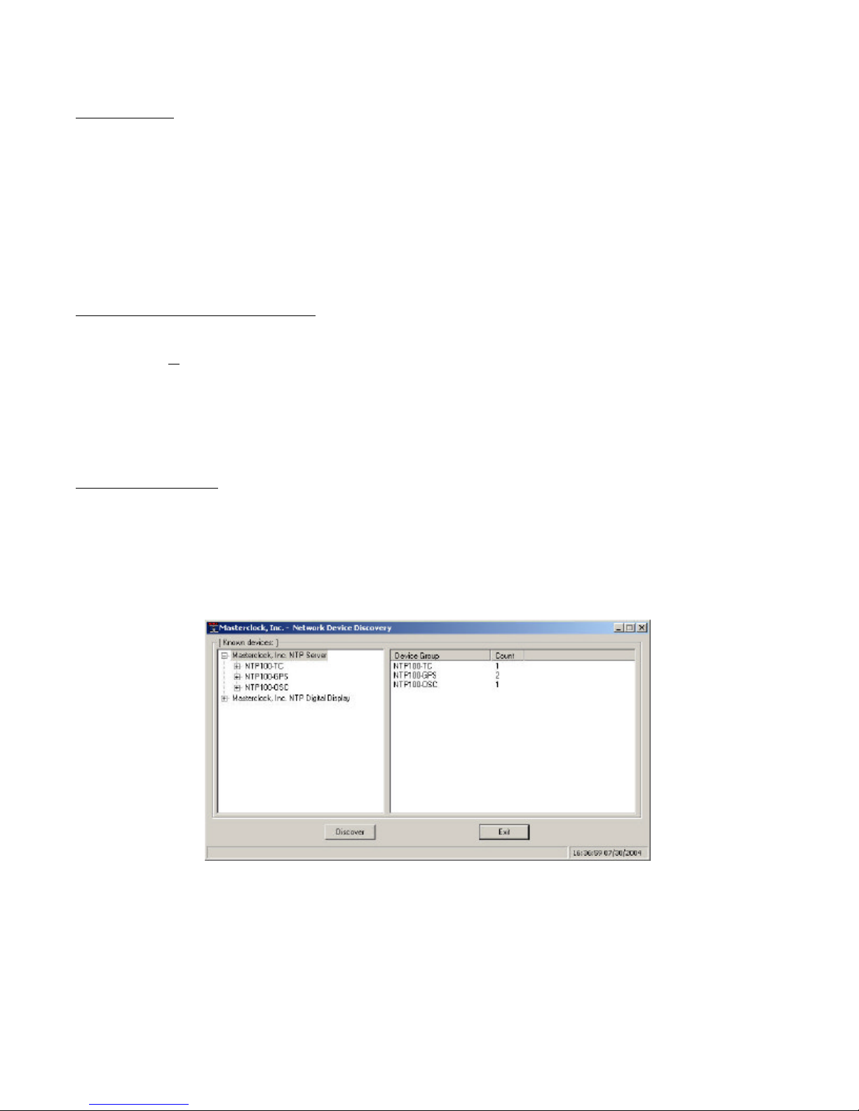
Click the Discover button on the lower left of the screen. All Masterclock, Inc. network appliances accessible on the
network will announce their presence. The real-time status bar will display the count of devices found. When complete,
a list of device families and groups will be displayed in the left pane of the WD window. The NTP100 is a member of
the Masterclock, Inc. NTP Server family. Click on the plus [+] sign to the left of any family or group to open and view
device types that were found.
Clicking on any device group will list in the right pane of the WD window all devices of that type found. Only the
devices shown in the right window can be managed. To configure another device group, click on the device name in the
left window and the device names will then appear in the right window, ready to be managed.
NTP100 – Rev 1.0.1 Dec-04
9
© Masterclock®, Inc.
Page 14
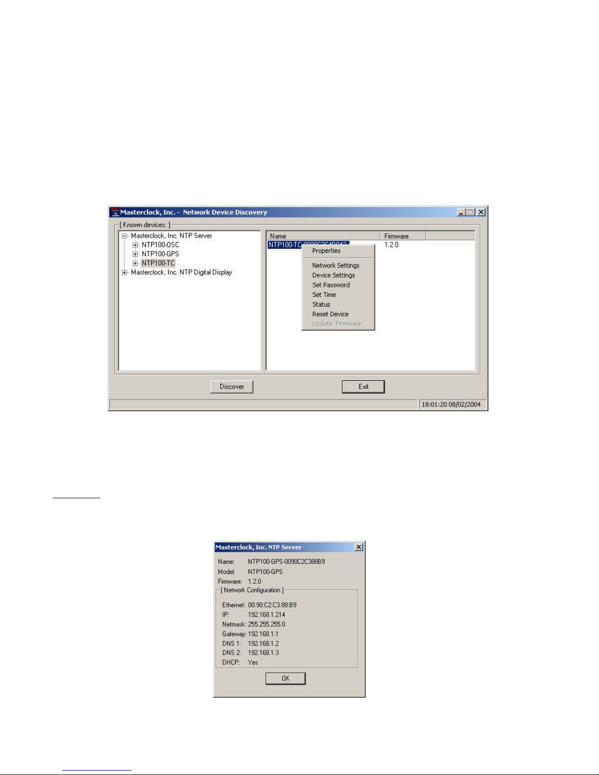
To configure and manage a device shown in the right window, double click or right mouse click the device name and a
menu appears. The current choices are:
• Properties
• Network Settings
• Device Settings
• Set Password
• Set Time
• Status
• Reset Device
NOTE: The Update Firmware option is reserved for future use and appears grayed out.
Clicking a menu choice opens a new window for that function. When working in the management windows, use the
Apply and OK button to accept changes that you have made. Use the Cancel button to exit the screen without applying
changes. NOTE: Cancel does not undo changes that have been saved using the Apply button.
Properties
The properties of the NTP100 device of interest can be viewed in summary form, using this selection. Under “Properties” the
device name, model, and network configuration settings are available.
NTP100 – Rev 1.0.1 Dec-04
10
© Masterclock®, Inc.
Page 15
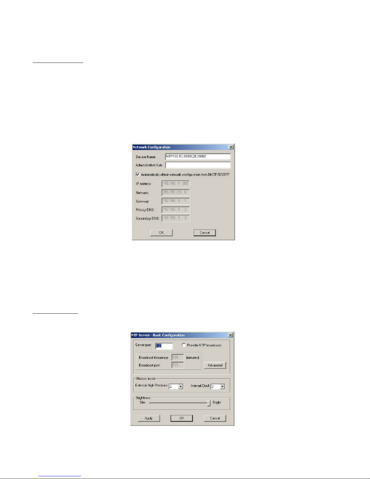
Network Configuration screen
Network Settings
The network settings must be established for the NTP100 to be accessible to the network. You must be a network
administrator or have their support to complete these functions. Your network administrator determines the information for
the Network Settings.
To use DHCP/BOOTP, click the checkbox on the screen, and click OK. (factory default).
To use a Static IP address, you must enter the IP address, Net Mask, Gateway, Primary DNS, and may enter a Secondary
DNS.
Each NTP100 is programmed at the factory with a factory device name which includes the numeric equivalent of its MAC
Address as the name extension. You can change the device name to one convenient for your site – preferably one that helps
you to later identify the exact physical location of the device.
[Note: the Administrative Hub configuration item is reserved for future use.]
Device Settings
Adjust configurable parameters affecting NTP100 operation using the available Basic and Advanced Device Settings.
Basic Device Configuration screen
NTP100 – Rev 1.0.1 Dec-04
11
© Masterclock®, Inc.
Page 16
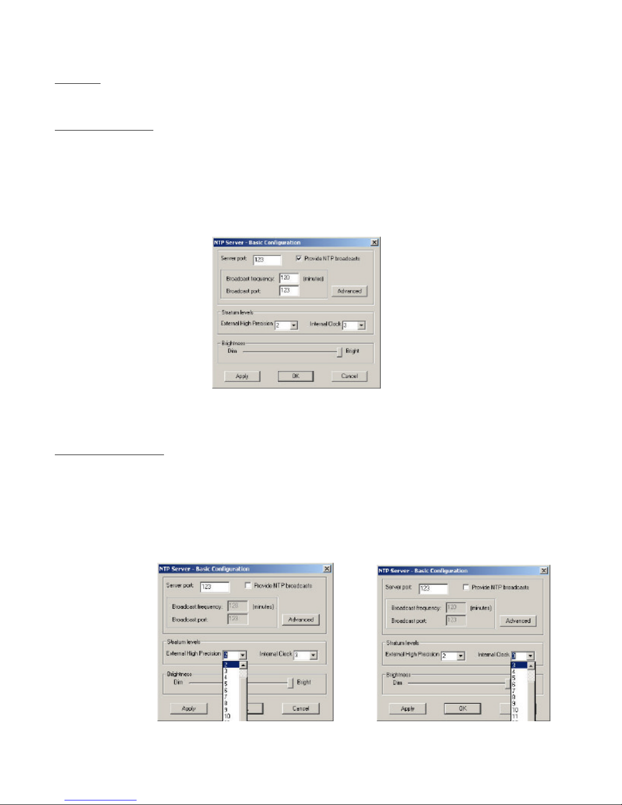
Server port - The default, well-known port for NTP service is 123. This can be changed as desired. Note that some
NTP/SNTP clients will expect NTP servers to operate on port 123 and cannot be configured to utilize alternate ports.
Provide NTP broadcasts – By default, the NTP100 will operate only in Query mode. The NTP100 can be set up to provide
NTP broadcasts. When enabled, the broadcast on/to port may be specified as well as the frequency that broadcasts will be
issued. This can be changed as desired.
NOTE: While providing NTP broadcasts, the NTP100 device can also continue to be queried.
Note that some NTP/SNTP clients will expect NTP servers to operate on port 123 and cannot be configured to utilize
alternate ports.
Selecting NTP broadcast mode
Stratum Level Assignment – a unique added feature of the NTP100 are stratum levels that are user -assignable. The NTP100
stratum levels are user assignable from 0-15, for both the external reference (primary – GPS or Time Code) and the internal
clock reference (secondary - TCXO).
The factory default stratum level settings for the NTP100 family are “2” for the External Ref, and “3” for the Internal Clock.
The Internal Clock stratum level cannot be adjusted to a reference level exceeding that of the External Reference.
A reference level of “0” is defined to be “disabled”.
NTP100 – Rev 1.0.1 Dec-04
Assignable Stratum Levels for the –GPS and –TC models
12
© Masterclock®, Inc.
Page 17
The time references for the various models are defined as:
MODEL External High Precision Internal Clock
NTP100-GPS
NTP100-TC
NTP100-OSC
GPS satellite signal
Time Code signal
Not Available TCXO & RTC.
TCXO (Temperature Compensated Crystal
Oscillator) , & RTC (real-time clock)
reference.
TCXO & RTC
In addition to the Stratum Level assignment, the allowable time dissemination duration for the operation on the Internal
Clock can be configured in the Advanced Configuration section (see below).
NOTE: The NTP100-GPS has a GPS receiver built in and can be considered a Stratum Level 1 device, as such, it can be
assigned a stratum level of “1” for the “External High Precision Reference” (defined to be: when locked to GPS).
NOTE: The NTP100-OSC does not have an external input, this feature will be grayed out for this model. Thus, the
stratum level can only be adjusted for the Internal Clock.
Brightness - The brightness or intensity of the NTP100’s front-panel time display can be adjusted from dim to bright.
The display can be dimmed here for low-light environments.
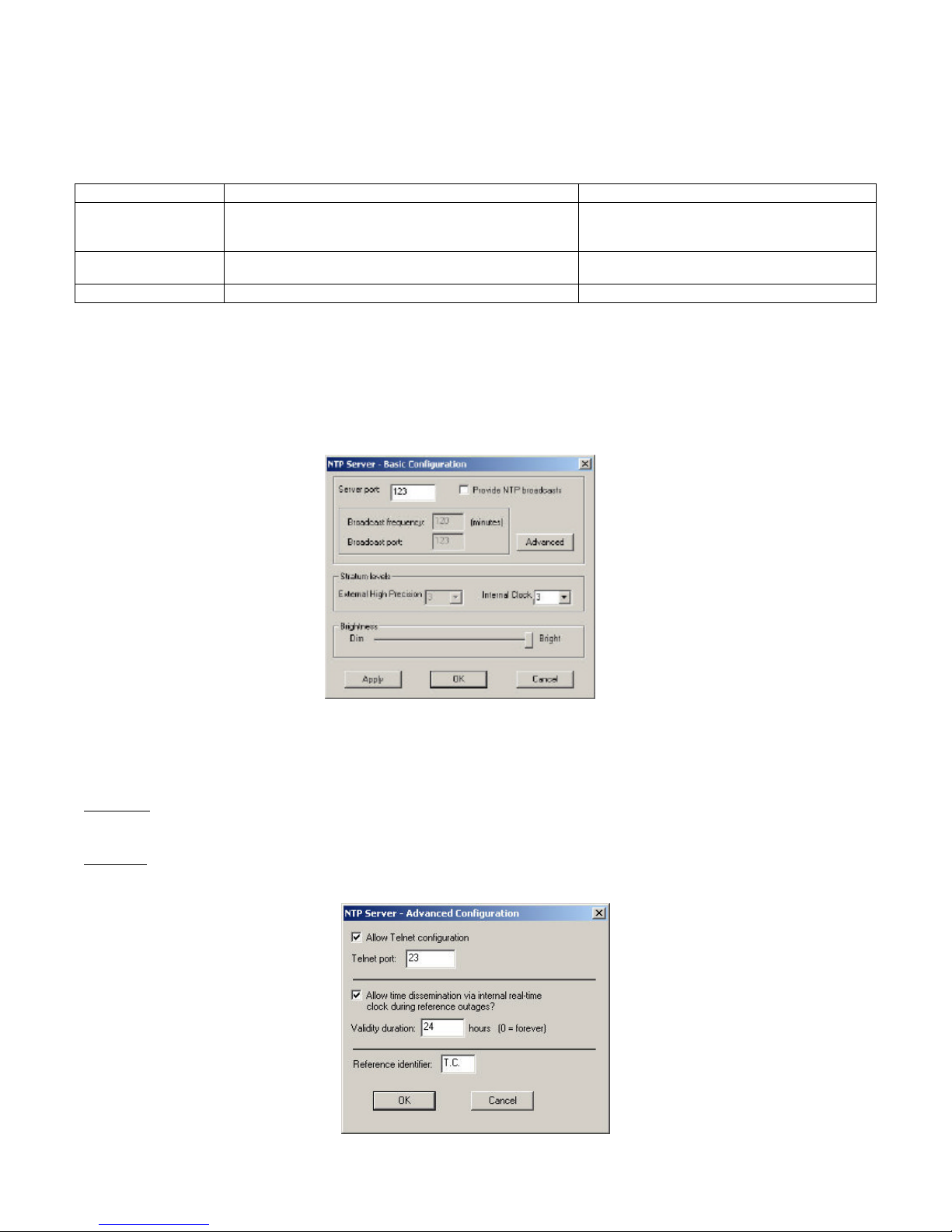
Advanced – Certain advanced features may be configured using the “Advanced” button. These include , access to the
telnet configuration interface and the ability to continue serving time during extended GPS or Time Code outages.
Advanced Device Settings Configuration screen
NTP100 – Rev 1.0.1 Dec-04
13
© Masterclock®, Inc.
Page 18
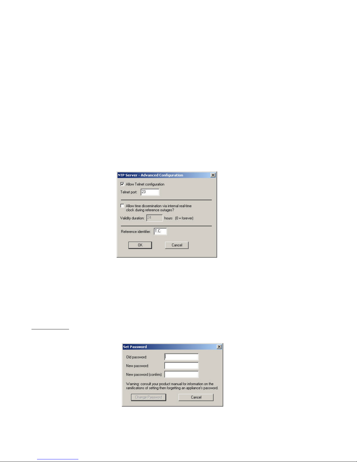
By default, the models NTP100-GPS and NTP100-TC will allow time dissemination (NTP service) for a period of 24 hours
from loss of the primary source (GPS or Time Code respectively). During this “free-wheeling” or “holdover” period, they
will rely on the internal real-time clock (RTC) and temperature compensated crystal oscillator,( TCXO )oscillator, which has
a typical holdover accuracy of +/- 1 min /year (+/- 165mSec drift over 24 hours or +/- 6.875 mSec drift over 1 hour).
The NTP100 (models –GPS and –TC) will continuously discipline the internal RTC and TXCO reference circuit to provide
maximum accuracy, while locked to the primary GPS or Time Code reference, when trusted and available).
The NTP100-OSC should periodically be set to the time of an external reference such as an NTP Server
The maximum “Validity” duration is adjustable in 1 hour increments. To always allow time dissemination and always
consider the internal clock source “valid”, set the validity duration to “0”
Deselect the “Allow time dissemination..” if you do not want the NTP100-GPS or NTP100-TC to serve time using the
internal RTC and TXCO oscillator.
Internal real-time clock reference disabled on –GPS & TC models
Set Password
Set/reset the password which controls access to the NTP100’s configuration.
SET/RESET password screen
NTP100 – Rev 1.0.1 Dec-04
14
© Masterclock®, Inc.
Page 19
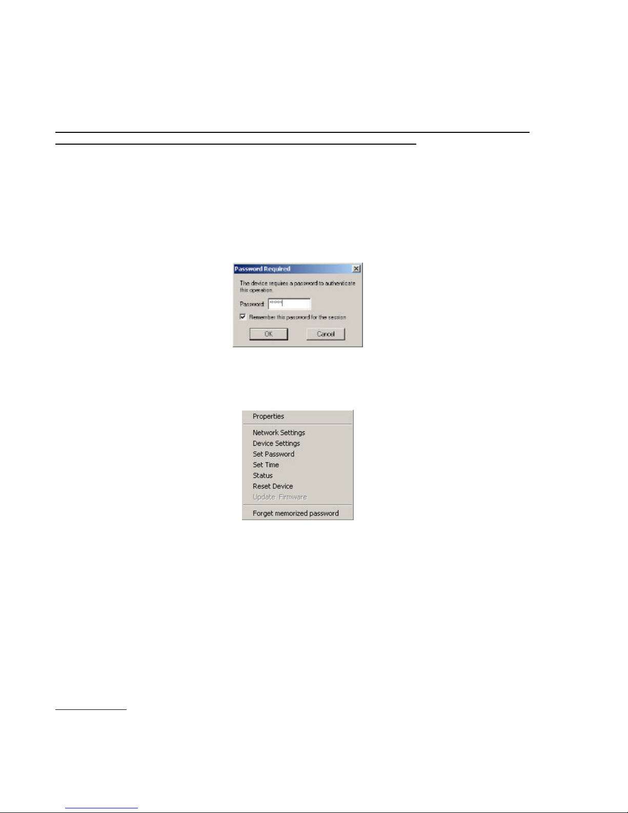
A password can be a maximum of 11 characters and may contain any sequence of letters, numbers, and common
punctuation. Passwords are case-sensitive.
WARNING: If the password is lost, the user must reset the NTP100 using the Reset button on the rear of the
unit. This will cause the unit to return all configuration to factory-default settings.
To remove a password, select the Set Password command. You will be prompted to enter the old password. Do not
enter anything into the New Password or Confirm Password fields. Click OK to save, or Cancel to leave the old
password unchanged.
When a password is set for an NTP100, each time you attempt to perform a configuration change you will be asked for
the password. You may enable the ‘Remember this password for the session’ checkbox to eliminate typing the
password for each configuration change. WinDiscovery will not remember the password after it is closed so maintain
passwords in a safe place.
[Note: each device listed can have a unique password associated with it, which will default to the factory default
password. You must enable the “Remember this password for the session’ checkbox for each device that is being
configured.]
Once a password has been memorized for a device, a “Forget memorized password” option is added to the right click
drop down menu for that unit.
[Note: the factory default password is: public]
Set Time/Date
The Set Time menu item lets you manually set the time and date for the NTP100. The function may be most useful for
demonstration, in lab situations, environments where an external signal is not available. The time for the NTP100 can
either be set to the time of the PC or a manual custom time can be entered.
NTP100 – Rev 1.0.1 Dec-04
15
© Masterclock®, Inc.
Page 20
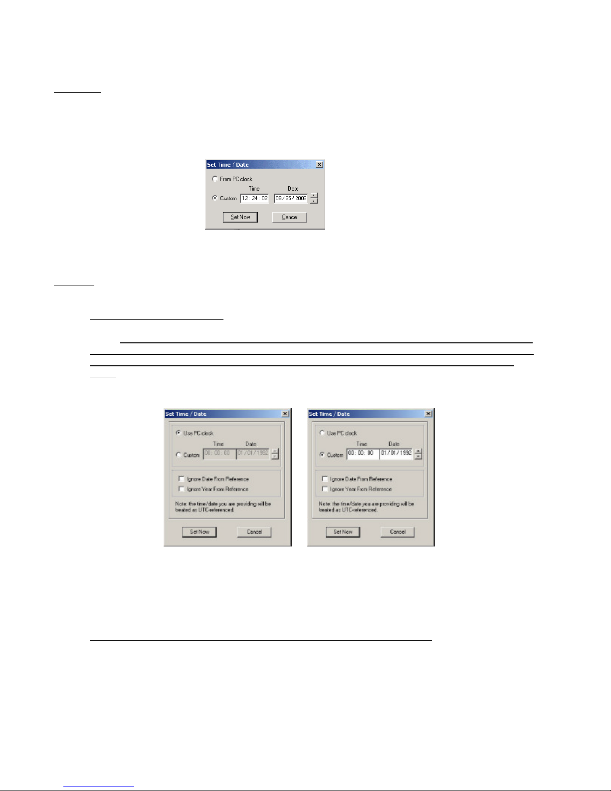
Model –GPS
When the NTP100-GPS achieves a GPS satellite fix, the continuous time/date obtained from GPS will
automatically overwrite any that is manually established. Therefore, practical ongoing use of this feature
requires the NTP100 to be disconnected from its GPS antenna.
Model -TC
Recommended (Default) Settings
NOTE: If your time code source outputs UTC referenced SMPTE 30/25/24 fps time code to the Leitch date
encoded format or IRIG-B/B1 time code to the IEEE 1344 standard, then leave both the “Ignore Date From
Reference” and “Ignore Year From Reference” unchecked and disabled (use factory default setting) as
shown. This will allow the automatic detection of time, date (or day of year), and year information from the
incoming time code signal. This is the normal (factory default) setting.
Set Time / Date screen, models –GPS and -OSC
Note: the time of day information will continue to be decoded from the time code signal, and will overwrite the manual
entry.
Using the default settings, will allow the automatic detection of time, date (or day of year), and year information from
the incoming time code signal. These are the recommended settings.
Date or Year Manual Overwrite (Ignore Date or Ignore Year from Reference) Feature
The date overwrite feature may be used if the Time Code signal (model –TC) does not contain date encoded
time code to either the SMPTE 30/25/24 fps Leitch date format standard or the IRIG-B/B(1) IEEE 1344
standard.
NTP100 – Rev 1.0.1 Dec-04
16
© Masterclock®, Inc.
Page 21
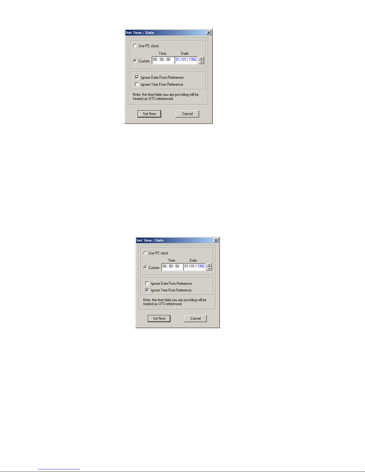
Date overwrite enabled
Ignore Date from Reference (external)
The year overwrite feature may be used if the Time Code signal (model –TC) does not contain year information in the
IRIG –B/B1 time code to the IEEE 1344 standard.
Note: the time data /information will continue to be decoded from the time code signal, and will always overwrite the
manual entry.
Ignore Year from Reference (external)
[Note: for the purpose of refreshing its internal clock, the NTP100 assumes the time and date entered is UTC.]
NTP100 – Rev 1.0.1 Dec-04
Year overwrite enabled –
17
© Masterclock®, Inc.
Page 22
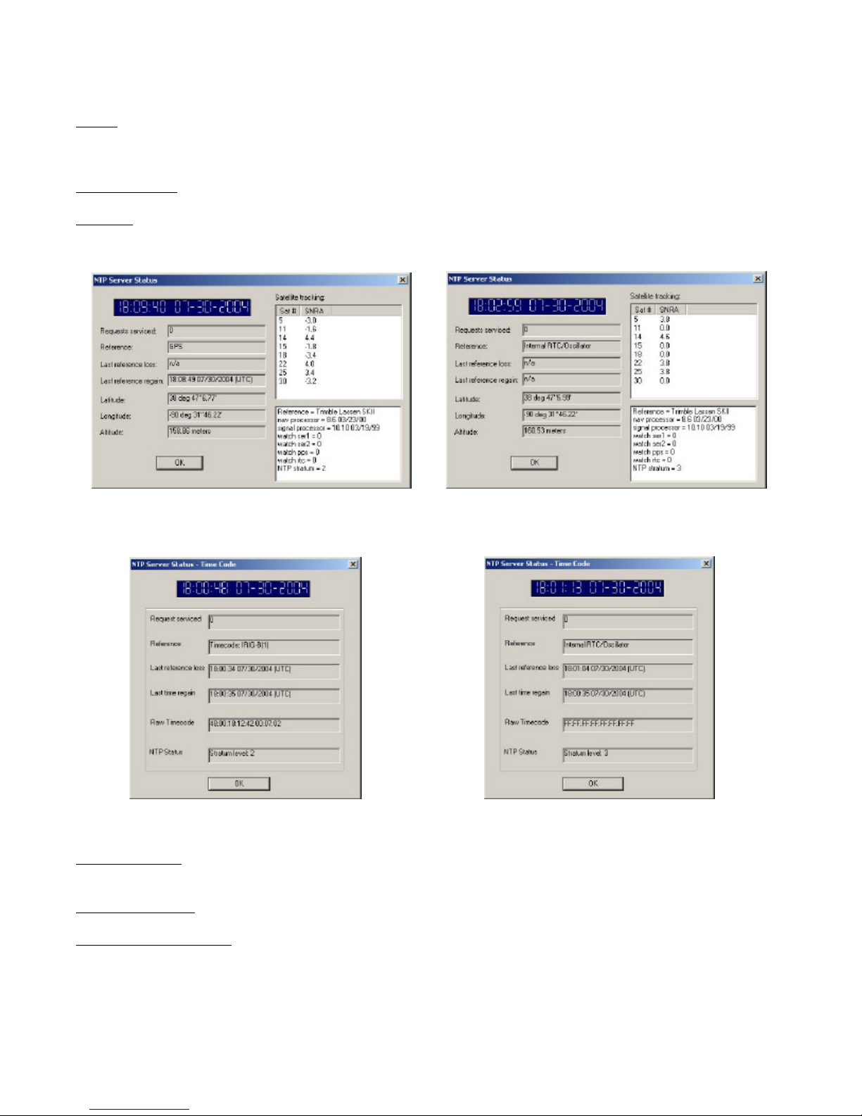
Status
Provides current status on the NTP100’s operation, including current UTC time/date on the unit, as well as other
operational information relative to the available device models.
Requests serviced – Number of NTP requests serviced since the unit was last powered on.
Reference – Current time reference.
NTP100-GPS: GPS when locked to GPS satellites, otherwise Internal Real-Time Clock.
NTP100-TC: Time Code format when locked to external time code input, otherwise Internal Real-Time Clock.
NTP100-OSC: Internal Real-Time Clock
Last reference loss – Last time/date upon which GPS satellite signal was lost, or n/a if the event has not occurred since
the last power on.
Last reference regain - Last time/date upon which GPS satellite or time code signal was re-acquired from a loss state.
NTP Status /Stratum Level - NTP stratum level for present reference as defined in the device configuration settings.
The remaining information in this status display is for technical support purposes only and is not useful for the end-user.
NTP100 – Rev 1.0.1 Dec-04
18
© Masterclock®, Inc.
Page 23
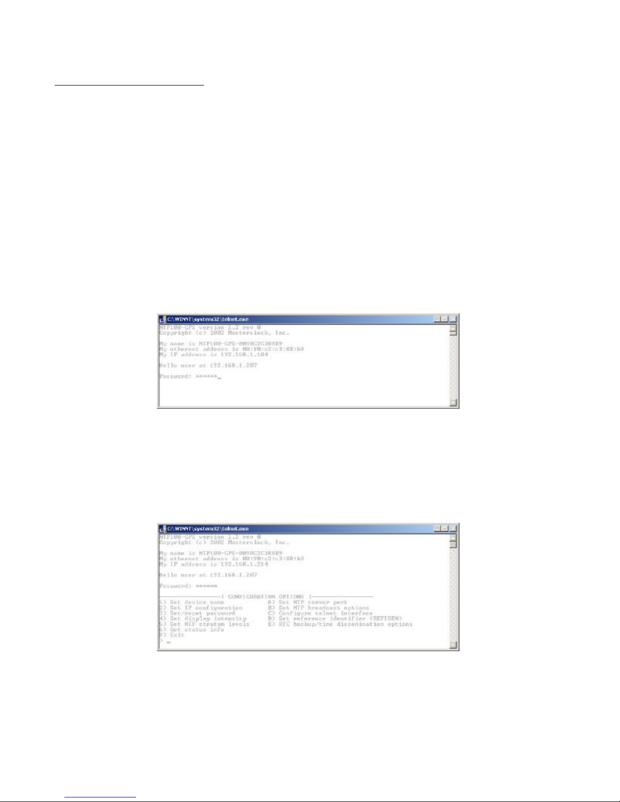
Telnet Terminal Configuration
A terminal-style configuration interface is available via Telnet. To connect with the NTP100 in this manner use any standard
Telnet client application, specifying the IP address of the NTP100 as the server with which to connect. The factory default
port is well-known telnet server port 23.
Configuration via Telnet may not be convenient for devices operating with a factory default network configuration since the
IP address is not known. Use the WinDiscovery application (or the RS-232 interface for models –GPS or –OSC) to establish
first-time networking configuration.
If you are not familiar with the Telnet application, ask your network system administrator for assistance.
[Note: for security purposes, the Telnet interface can be disabled. When disabled, you will no longer be able to access the
unit with Telnet. To re-enable the Telnet feature, one of the other configuration methods must be used, or the unit must be
reset to factory default configuration.]
Upon entering the NTP100 configuration via Telnet, the initial screen is shown below. The NTP100 displays its firmware
version, its name, ethernet address, IP address, and the IP address of the PC with which you are accessing it. A login prompt
is presented if a password has been configured for the unit. The configuration menu will be displayed when the correct
password has been provided.
Enter the Number or Alpha Letter corresponding to the command and press the enter key. Current configuration or default
answers are displayed in brackets. ‘Enter key only’ will retain the current entry/default.
NTP100 – Rev 1.0.1 Dec-04
19
© Masterclock®, Inc.
Page 24
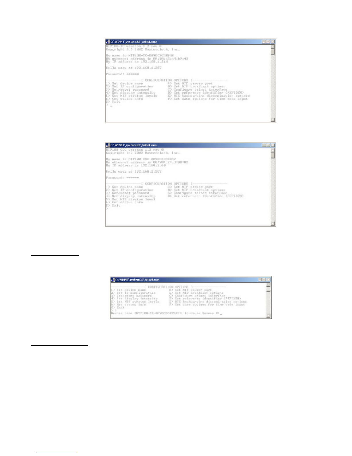
Set Device Name
To set the device name, select option ‘1’. Enter the desired device name. As with the WinDiscovery configuration utility,
you may enter a unique alphanumeric device name.
Set IP Configuration
To set the IP Configuration, select option ‘2’. NOTE: If you select this option, you will be disconnected from the session
upon completion, whether you actually change any entries or not. You have the choice of using DHCP for automatic IP
Configuration or entering the data in these screens. If you select DHCP, no other questions will be displayed, you will be
disconnected from the session, and you will not be able to Telnet to this NTP100 until you learn the DHCP-provided IP
address. To manually enter the IP information, enter ‘N’ for the DHCP (or Enter for the default), and enter the IP, Netmask,
Gateway, Primary DNS and Secondary DNS server.
NTP100 – Rev 1.0.1 Dec-04
20
© Masterclock®, Inc.
Page 25
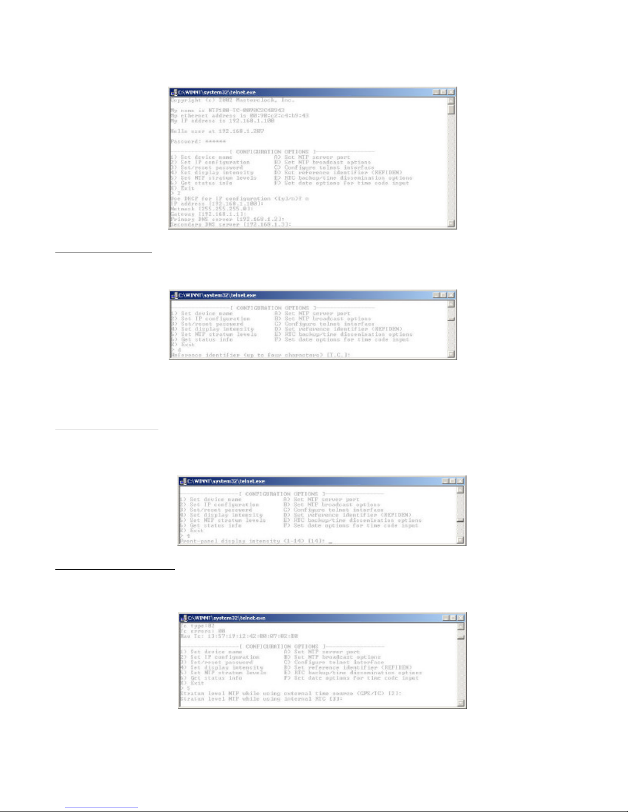
Set/Reset Password
To set, change or remove the password, enter ‘3’ for this option. Bear in mind that a lost/forgotten password cannot be
recovered.
[Note: the factory default password is: public]
Set Display Intensity
To adjust the clock display intensity (brightness), select option ‘4’. Intensity is controlled with a scale of 1 to 14 with 14
being brightest. Enter the value for the desired intensity setting.
Set NTP Stratum Levels
To adjust the clock display intensity (brightness), select option ‘5’. An added-feature of the NTP100 are stratum levels that
are user-assignable. The NTP100 stratum levels are user assignable from 0-15, for both the external reference (primary –
GPS or Time Code) and the internal clock reference (secondary - TCXO).
The factory default stratum level settings for the NTP100 family are “2” for the External Ref, and “3” for the Internal Clock.
The Internal Clock stratum level cannot be adjusted to a reference level exceeding that of the External Reference.
NTP100 – Rev 1.0.1 Dec-04
21
© Masterclock®, Inc.
Page 26
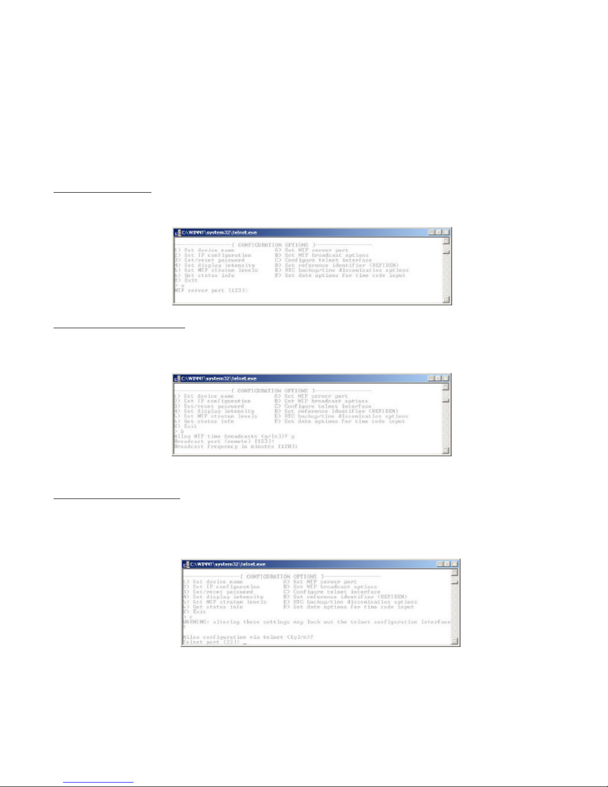
A stratum reference level of “0” is defined to be “disabled”.
In addition to the Stratum Level assignment, the allowable time dissemination duration for the operation on the Internal
Clock can be configured in the Advanced Configuration section (see below).
NOTE: The NTP100-GPS has a GPS receiver built in and can be considered a Stratum Level 1 device, as such, it can be
assigned a stratum level of “1” for the “External High Precision Reference” (defined to be: when locked to GPS).
Set NTP Server Port
To configure the port that the NTP100 serves time requests on, select option ‘A’. The well-known port for NTP server
services is 123.
Set NTP Broadcast Options
To configure br oadcast transmission options, select option ‘B’. This allows broadcast transmission of NTP packets to be
enabled or disabled, and to adjust the broadcast port and transmission frequency.
Configure Telnet Interface
To adjust this configuration, select option ‘C’. If Telnet is allowed, define the telnet port. The well-known port for telnet
services is 23. If turned off, the telnet session will be ended and the user must use WinDiscovery, RS-232 access, or the
Reset Configuration button to re-enable it.
NTP100 – Rev 1.0.1 Dec-04
22
© Masterclock®, Inc.
Page 27
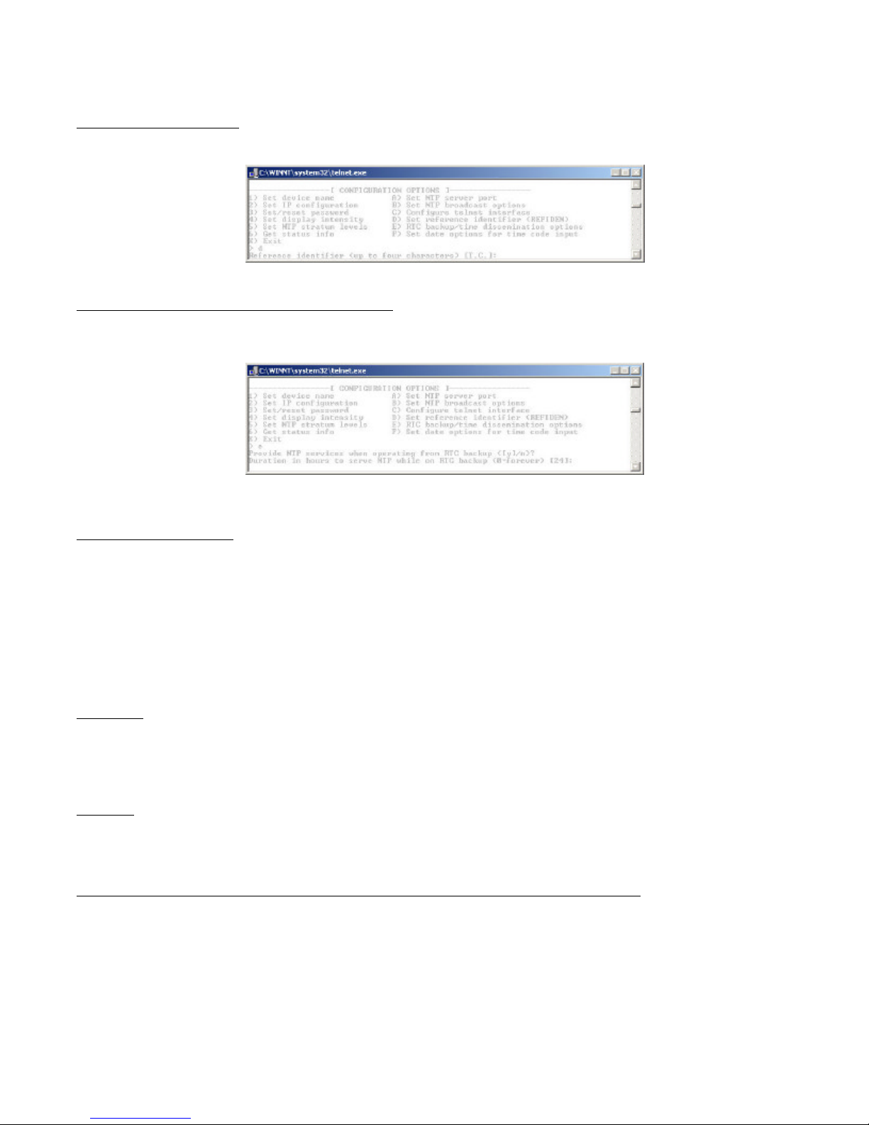
Set Reference Identifier
To adjust this configuration, select option ‘D’.
Set RTC Backup/Time Dissemination Options
To adjust this configuration, select option ‘E’. By default the NTP100-GPS & -TC will allow time dissemination using the
internal real-time clock and TCXO for 24 hours.
Set Time/Date Options
To adjust this configuration, select option ‘F’.
The Set Time/Date menu item lets you manually set the time and date for the NTP100. The function may be most
useful for demonstration, in lab situations, environments where an external signal is not available.
The time for the NTP100 can either be set to the time of the PC or a manual custom time can be entered.
Because of the special considerations for accommodating non -date encoded SMPTE & IRIG-B/B1 time code formats,
the NTP100-TC Set Time/Date Screen or menu will differ from the –GPS and –OSC models.
Model –GPS
When the NTP100-GPS achieves a GPS satellite fix, the continuous time/date obtained from GPS will automatically
overwrite any that is manually established. Therefore, practical ongoing use of this feature requires the NTP100 to be
disconnected from its GPS antenna.
Model -TC
Because of the special considerations for accommodating non -date encoded SMPTE & IRIG-B/B1 time code formats,
the NTP100-TC Set Time/Date Screen will differ from the –GPS and –OSC models.
Automatic Detection mode (for date & year encoded time code) – Recommended (default) Settings
If your time code source outputs UTC referenced SMPTE 30/25/24 fps time code to the Leitch date encoded format
or IRIG-B/B1 time code to the IEEE 1344 standard, then leave the “Ignore Date From Reference” and “Ignore Year
From Reference” disabled (factory default setting) by entering “n” for no , as shown. This will allow the automatic
detection of time, date (or day of year), and year information from the incoming time code signal.
NTP100 – Rev 1.0.1 Dec-04
23
© Masterclock®, Inc.
Page 28
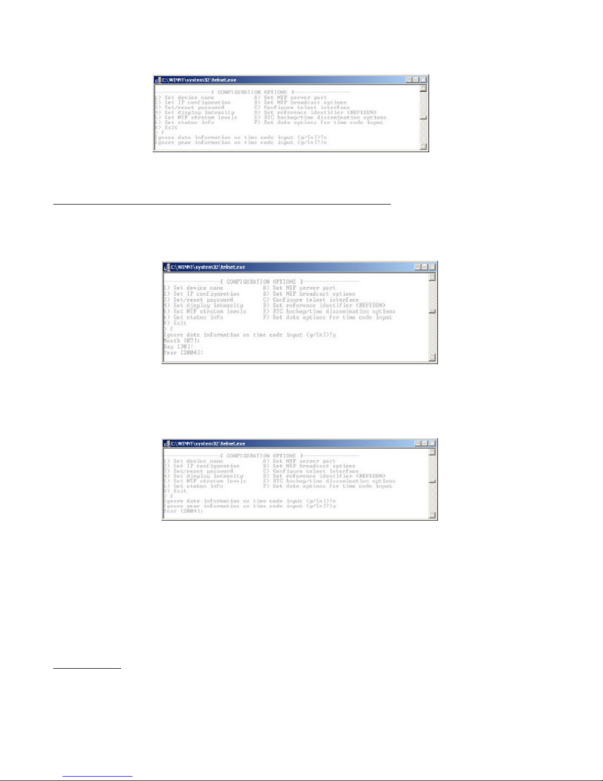
Date or Year Manual Overwrite (Ignore Date or Ignore Year from Reference) Feature
The date overwrite feature may be used if the Time Code signal (model –TC) does not contain date encoded time code
to either the SMPTE 30/25/24 fps Leitch date format standard IRIG-B/B(1) IEEE 1344 standard.
The year overwrite feature may be used if the Time Code signal (model –TC) does not contain year information in the
time code to either the SMPTE 30/25/24 fps Leitch date format standard IRIG-B/B(1) IEEE 1344 standard.
The time data /information will continue to be decoded from the time code signal, and will always overwrite the manual
entry.
[Note: for the purpose of refreshing its internal clock, the NTP100 assumes the time and date entered is UTC.]
Exiting Telnet
To exit the terminal interface, select option ‘X’.
NTP100 – Rev 1.0.1 Dec-04
24
© Masterclock®, Inc.
Page 29

RS-232 Terminal Configuration (specific to models NTP100-GPS and NTP100-OSC only)
The RS-232 configuration interface behaves identically to the telnet interface. To communicate with the NTP100 in this
manner connect any RS-232 terminal or PC serial port and serial terminal application to the DB-9 connector on the rear of
the NTP100 unit (labeled RS-232). A “straight-through” 9-wire cable should be used. The settings for the RS-232 port are:
9600 baud, 8 data bits, 1 stop bit, no parity. Consult the section entitled Telnet Terminal Configuration for details on how to
change configuration using the terminal interface.
NTP Client Information
Any computer system desiring to synchronize its time to the NTP100 server must incorporate an NTP client. A NTP client is
responsible for asking the NTP server for time/date information, or in some cases simply listening on the network for NTP
time broadcasts, then setting the internal time of the computer or device. NTP client applications come in a variety of
flavors, supporting different features, and with different levels of accuracy, fault tolerance, and reporting. Many are
inexpensive to license, or free.
Listing for NTP clients can be found at the NTP home page, http://www.ntp.org, as well as many shareware/freeware file
search engines.
Dimension 4
Operates in most Windows environments. Concise user interface, can be minimized to the system tray.
http://www.thinkman.com/
TimeSync
Operates in a Windows NT/2000 environment, and can run as a service.
http://www.intsoft.com
XNTP
XNTP is the commonly used Un*x distribution of NTP server/client software. XNTP is distributed with many Un*x
operating system packages, and is licensed for use without fee. The distribution can also be built for Windows operating
systems although it is generally not needed for the Windows 2000/XP platforms (see Win32Time below).
http://www.ntp.org
Win32Time (W32Time)
This application, somewhat based upon NTP, is a Microsoft-specific time synchronization service that is incorporated into
Windows 2000, Windows XP, and probably future Microsoft operating systems.
Only Windows server running as PDC (primary domain controller) can query an external NTP server to set time.
To configure a PDC computer running Win32Time to query an external NTP server, execute the ‘net time’ command from a
command prompt.
Configure the external NTP source:
Ø net time /setsntp:xxx (where xxx is the name or IP address of an NTP server)
View the currently configured NTP source:
Ø net time /query
A dissertation on configuring and deploying Win32Time in an enterprise network environment is beyond the scope of this
manual. Please refer to the documentation included with your Windows 2000/XP operating system for details. The
Microsoft Knowledge Base also contains a number of useful articles. Search on the ‘net time’ and ‘w32time’ keywords.
NTP100 – Rev 1.0.1 Dec-04
25
© Masterclock®, Inc.
Page 30

Disclaimer
Masterclock, Inc. cannot provide technical support for the above-described client packages. Masterclock, Inc. makes no
warranty, either expressed or implied, with respect to any of these client software packages. Masterclock, Inc. specifically
disclaims the implied warranties of merchantability or fitness for a particular purpose.
Troubleshooting Tips
Problem: Unable to find the NTP100 on the network with WinDiscovery
Connectivity issues:
1. Verify that the NTP100 and the computer running WinDiscovery are attached to the network.
2. Verify that all network cables, hubs, etc. are in proper working order. Be sure that ethernet crossover cables are not
being used where inappropriate.
Router/Firewall issues:
1. Verify that the NTP100 is on the same logical network as the computer from which you are running WinDiscovery. If
the computer is separated from the NTP100 by a router, that is, on a remote network - it is likely that the router is
blocking communication with the device. Run WinDiscovery from a computer within the remote network, or ask a
network system administrator to configure the router in question to pass through (both directions) UDP traffic on port
6163.
2. Some routers will not forward UDP broadcasts across networks – currently, this capability is required to use
WinDiscovery for enterprise-level management of Masterclock, Inc. network appliances.
3. If you are running a personal firewall product, such as ZoneAlarmTM or BlackICETM, you must adjust their configuration
to pass through (both directions) UDP traffic on port 6163.
Other:
1. If the NTP100 has been configured to use DHCP for network configuration but no DHCP/BOOTP server is present, the
NTP100 may not respond to discovery requests for up to twenty seconds after power-on. [Note: DHCP is disabled as a
factory-default.]
Problem: Unable to communicate with the NTP100 on the network with Telnet
2. If the NTP100 has been configured to use DHCP for network configuration the but no DHCP/BOOTP server is present,
the NTP100 may not respond to discovery requests for up to twenty seconds after power-on. [Note: DHCP is disabled
as a factory-default.]
[Note: for security purposes, the Telnet interface can be disabled. When disabled, you will no longer be able to access the
unit with Telnet. To re-enable the Telnet feature, one of the other configuration methods must be used, or the unit must be
reset to factory default configuration.]
Problem: NTP client is unable to communicate with the NTP100
1. Verify that the NTP100 is attached to the network.
2. Verify that all network cables, hubs, etc. are in proper working order. Be sure that ethernet crossover cables are not
being used where inappropriate.
3. Verify that the NTP100 is actually reachable from the client. Try “pinging” the IP address of the NTP100. If this fails, it
is possible that the NTP100 has an invalid network configuration or that the network is down. Consult your network
administrator for assistance.
4. Verify that the NTP100 is set to output if operating in internal oscillator/real time clock mode and that the maximum
time difference has not been exceeded.
NTP100 – Rev 1.0.1 Dec-04
26
© Masterclock®, Inc.
Page 31

Problem: NTP client indicates that the NTP100 is providing invalid time, or has flagged time as invalid.
The NTP100 will always answer NTP requests, but will flag time as invalid if it does not have trusted time to distribute. This
may occur temporarily during GPS navigation state changes, or before the first GPS acquisition after the NTP100 has been
powered on after being off for an extended period of time.
By default, the NTP100 will begin flagging time invalid after 24 hours of consecutive GPS acquisition failure or non operation (powered off). This is a protective feature, and can be adjusted or disabled if desired – see device configuration
sections.
Problem: You have lost your password
The password cannot be recovered if it is lost. Reset the NTP100 to factory default configuration using the procedure
described in the Configuration section.
Problem: The UTC date/time is incorrect and the unit does not retain configuration settings when powered up.
The NTP100 maintains its internal configuration and settings in battery backed memory located on the RTC chip. The
battery supplies power to the TCXO 32kHz Oscillator and RTC when the unit is powered off. This allows the internal
configuration to be maintained and the time and date to increment, when power is off. Under normal operating condition, the
memory devices maintaining the RTC data and configuration settings is powered by the external DC power supply and does
not rely on the battery for data retention.
Note: If the NTP100 does not retain its configuration, or its Date/Time settings (often indicated by the front panel time
display counting up from ‘zero’) the battery will likely need replacement.
Check and replace the battery, if necessary. The battery type is a ‘replaceable’ 3V lithium coin cell battery and can be
replaced by a qualified technician, or the unit can be sent to technical support at Masterclock for repair/replacement for
service using our RMA procedure. The battery size/type vary for the various models. See the “Specifications” section for
details on the recommended battery replacement, or contact technical support for assistance.
Time Code Decoding Issues
The following items are specific to the NTP100-TC model.
The easiest way to verify that the NTP100-TC is decoding time code is to observe the status of the LED on the front panel
and with the WinDiscovery “Status”. The green LED will be flashing at 1 pulse per second when the NTP100-TC is
properly decoding time code. If the LED is not lit, or is not flashing at 1 pulse per second (1 Hz), then there is a problem
with the time code signal.
Time code decoding problems can include any of the following:
• no time code present
• ground loops or other interference
• bad/intermittent cables, wiring, or connectors
• a signal level that is out of range (too high or too low)
• a signal level that is fluctuating
• a time code type that the NTP100-TC does not support
Before concluding that there is a physical problem with time code decoding on the NTP100-TC, please rule out all of the
above possibilities.
NTP100 – Rev 1.0.1 Dec-04
27
© Masterclock®, Inc.
Page 32

Problem: The UTC time (&/or date ) is incorrect
There are several potential failure points:
• invalid or missing time code source,
• date/year overwrite function for non-date encoded time code may be enabled improperly,
• battery may need replacement (see the previous problem item)
• an NTP client or Windows local time zone configuration may be misleading you.
Verify that your time code source is generating the UTC referenced time and date that you expect, and that this time code
format is at an acceptable signal level and quality that can be detected at the receiver (input to the NTP100-TC). Please see
the NTP100-TC specifications for details.
If you have a time code source from an alternate vendor, be sure that your time code actually contains encoded date
information to the Leitch or IEEE1344 time code formats. For SMPTE-type time codes the date must be encoded to the
LeitchTM specification and, for IRIG-B/B(1) time code format, to the IEEE 1344 specification. Verify through your master
clock’s documentation that date encoding is both supported and enabled.
If you are using an acceptable UTC time code source with date encoded time code, ensure that the time/date overwrite
function of the NTP100-TC is not enabled.
If your time code source is making daylight savings time adjustments (during DST) or time zone offsets these must be
functions must be disabled. The NTP100-TC only accepts and decodes UTC referenced time code.
If you are using an NTP client or the date/time display such as on a Windows system, this may provide misleading
information as these may be configured to display local time zone and daylight saving time information. This is configured
through the Date/Time applet in the Control Panel. Use the WinDiscovery or Telnet interface or a system with the time zone
and DST disabled. Confirm the time using the front panel LED display of the NTP100-TC.
A Time Code Reader Card with a Time Code Viewer utility or a time code display are useful diagnostic tools in making these
determinations regarding the source. These items are available for separate purchase from Masterclock, Inc.
Masterclock,Inc also provides, for separate purchase, date encoded time code sources such as time code generators,
oscillators, and converters to industry standard time code formats which can be used directly with the autodetection circuitry
of the NTP100-TC. Please contact Masterclock, Inc. to inquire about available date-encoded time code sources.
If these troubleshooting tips do not solve your problem, contact technical support at [email protected] or call (636)
724-3666.
NTP100 – Rev 1.0.1 Dec-04
28
© Masterclock®, Inc.
Page 33
Specifications
Communications – Protocol
• NTP version 4 / stratum 1 – UDP, port 123 (default)
• Telnet – TCP, port 23 (default)
• Control/discovery protocol – UDP, port 6163
• RS-232 (ASCII) - 9600 baud, 8 data bits, one stop bit, no parity (Models NTP100-GPS and NTP100-OSC only)
Communications – I/O
Ethernet (10mbps)............................................................RJ45, 10baseT
RS-232 ............................................................................DB9 male, ((Models NTP100-GPS and NTP100-OSC only)
Time Code Input – (model –TC)
Time Code Input Connector .............................................BNC-female, balanced,
Time Code Input Impedance.............................................>100kOhm
Supported Time Code Formats.........................................(Auto- Detection, Auto-Gain Adjust)
........................................................................................SMPTE/EBU/Film ,LTC (30/25/24 fps) to Leitch Encoding
........................................................................................IRIG-B pulse width coded DC (unmodulated), IEEE 1344
IRIG-B(1) 1 kHz Amplitude Modulated , IEEE 1344
Power Requirements
DC Input Voltage .............................................................9–28 VDC
DC Input Connector .........................................................Male Switchcraft locking (p/n L722A)
Optional Threaded Female DC Input Power plug...........Switchcraft p/n S761K (available by special order)
Power Consumption .........................................................@12V - 150 mA (1.8W)
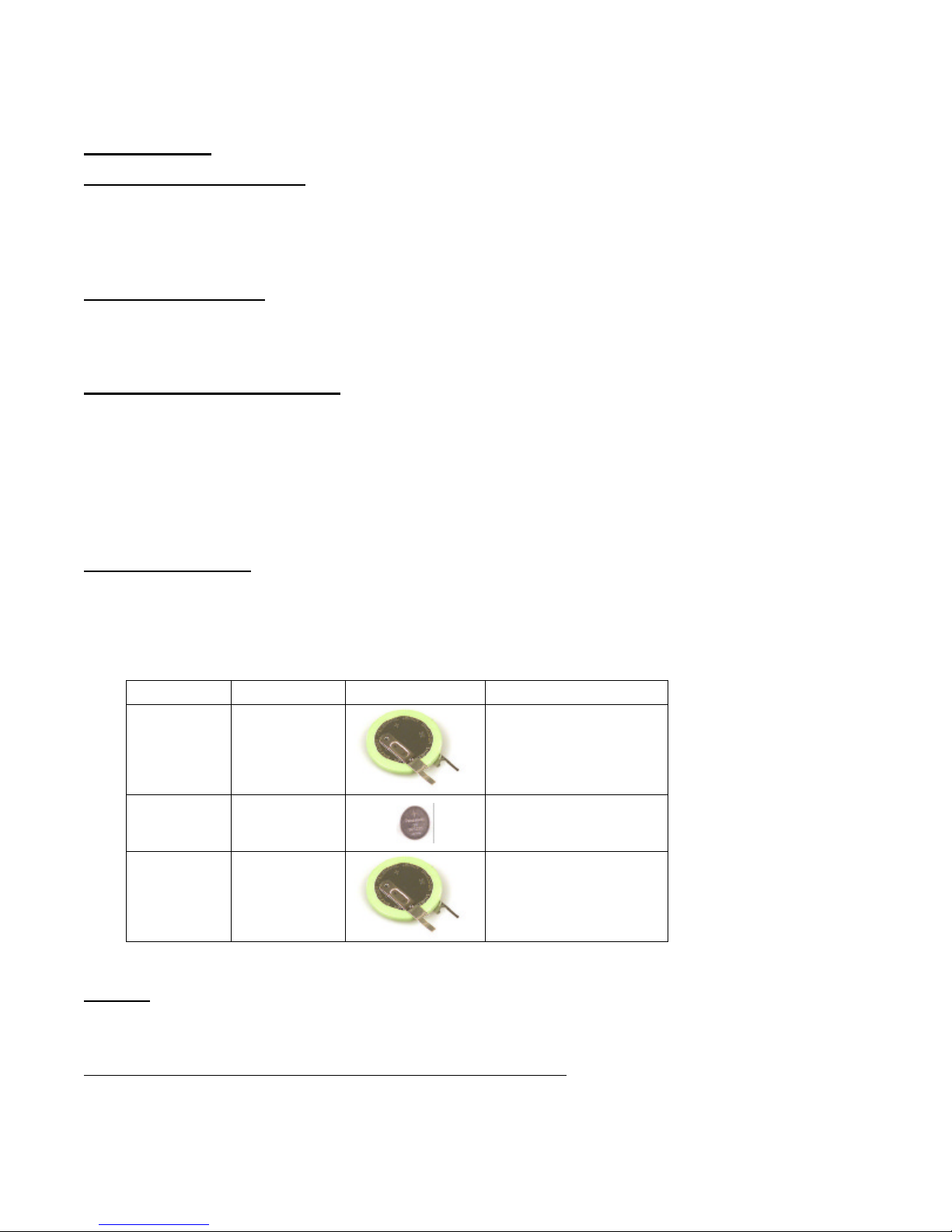
Battery............................................................................. Lithium Coin Cell,( see table below).
MODEL Battery Replacement
Panasonic BR2330
3V, 255mAh
NTP100-GPS
NTP100-TC
NTP100-OSC
Lithium Coin
Cell
3V,48 mAh
Lithium Coin
Cell
3V,255 mAh
Lithium Coin
Cell
Physical
Size..................................................................................6.75 x 4.13 x 1.5 in. (17.15 x 10.48 x 3.81 cm)
Weight............................................................................. 17.3 oz. (490.5 g)
Pre-Amplified Antenna (required for model NTP100-GPS only)
3V,255 mAh,
23mm, with vertical
(solder) tabs ,
or equivalent
Panasonic BR1225, 3V,
48mAh, 12.5mm
or equivalent
Panasonic BR2330
3V,255 mAh,
23mm, with vertical
(solder) tabs ,
or equivalent
Frequency........................................................................1575 MHz ± 10 MHz
Polarization......................................................................Right Hand Circular
Impedance ....................................................................... 50 Ohm
NTP100 – Rev 1.0.1 Dec-04
29
© Masterclock®, Inc.
Page 34

Weight............................................................................. 8.3 Oz (235 gr.)
Voltage............................................................................5 VDC
Power Consumption .........................................................@ 20 ma (.24W)
Gain.................................................................................26 dB Standard
Temperature.....................................................................-40 to +70°
Operating/Storage Temperature & Humidity
Operating Temperature.....................................................0 to +40°C
Relative Humidity.........................................................Up to 90% (non condensing @ 25°C)
Storage Temperature........................................................-40 to +70° C
Relative Humidity.........................................................Up to 90% (non condensing @ 25°C)
NTP100 – Rev 1.0.1 Dec-04
30
© Masterclock®, Inc.
Page 35

LIMITED WARRANTY
This Masterclock, Inc. (hereinafter MC) product warranty extends to the original purchaser.
MC warrants the NTP100 against defects in materials and workmanship for a period of one year from date of sale. If MC receives
notice of such defects during the warranty period, MC will, at its option, either repair or replace products, which prove to be
defective.
Should MC be unable to repair or replace the product within a reasonable amount of time, the customer's alternate remedy shall be a
refund of the purchase price upon return of the product to MC. This warranty gives the customer specific legal rights. Other rights,
which vary from state to state or province to province, may be available.
Exclusions
The above warranty shall not apply to defects resulting from improper or inadequate installation or maintenance by the customer,
customer-supplied software or interfacing, unauthorized modification or misuse, operation outside of the environmental
specifications for the product or improper site preparation and maintenance (if applicable).
Warranty Limitations
MC MAKES NO OTHER WARRANTY, EITHER EXPRESSED OR IMPLIED, WITH RESPECT TO THIS PRODUCT. MC
SPECIFICALLY DISCLAIMS THE IMPLIED WARRANTIES OF MERCHANTABILITY OR FITNESS FOR A PARTICULAR
PURPOSE.
In any state or province which does not allow the foregoing disclaimer, any implied warranty of merchantability or fitness for a
particular purpose imposed by law in those states or provinces is limited to the one-year duration of the written warranty.
Exclusive Remedies
THE REMEDIES PROVIDED HEREIN ARE THE CUSTOMER'S SOLE AND EXCLUSIVE REMEDIES. IN NO EVENT
SHALL MC BE LIABLE FOR ANY DIRECT, INDIRECT, SPECIAL, INCIDENTAL, OR CONSEQUENTIAL DAMAGES,
WHETHER BASED ON CONTRACT, TORT, OR ANY OTHER LEGAL THEORY.
In any state or province which does not allow the foregoing exclusion or limitation of incidental or consequential damages, the customer
may have other remedies.
NTP100 – Rev 1.0.1 Dec-04
31
© Masterclock®, Inc.
 Loading...