

Page 1
1
Masterclock MCR1000 User Manual – v.2013.08.01
Page 2

2
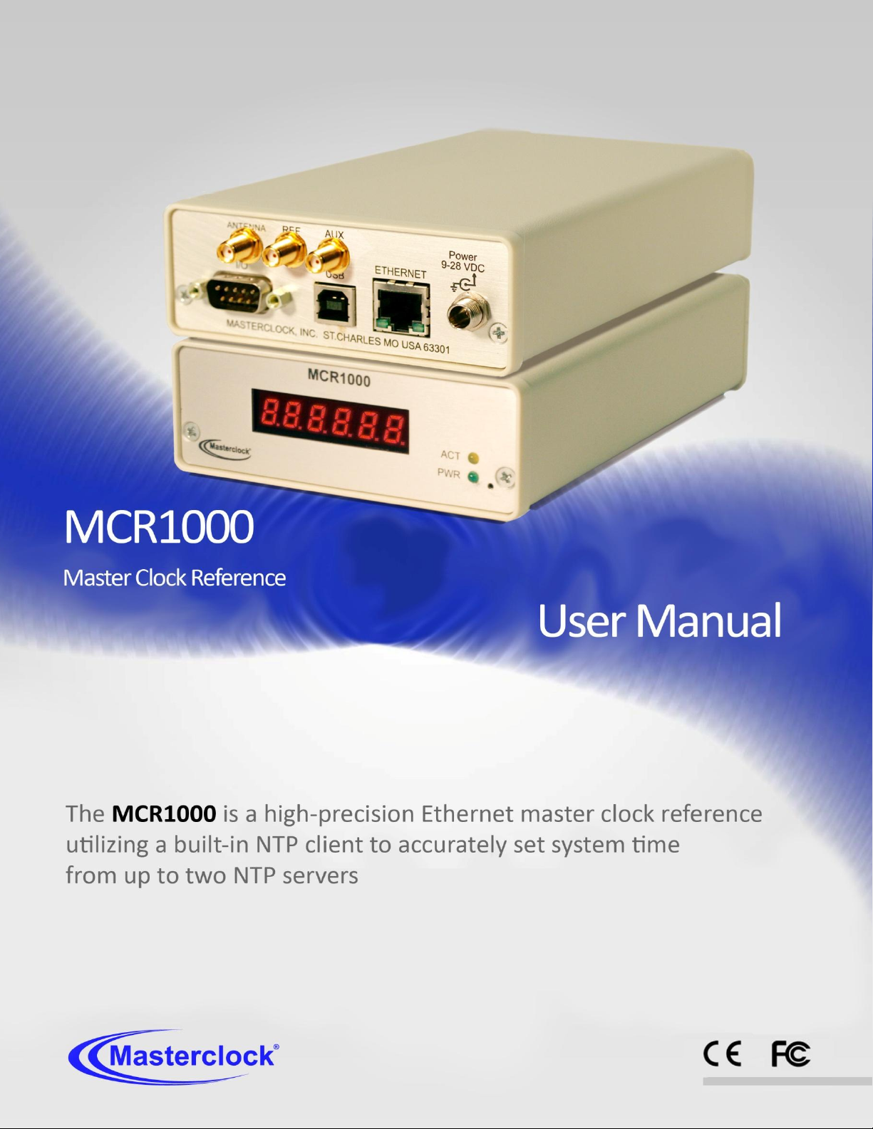
The MCR1000 is a high-precision time
and frequency reference system based on
NTP (Network Time Protocol) over the
Ethernet. Designed for the desk top or
rack mount, this single input and output
generator serves commercial
establishments, industry, military and
laboratory environments. GPS, NMEA,
NENA and Time Code options are also
available.
Thank you for your purchase of a
MCR1000 precision time and frequency
reference system from Masterclock.
Here you’ll find instructions for
unpacking and installing your MCR1000,
proper care and configuration.
We are here to help. You can reach us
using various contact methods (phone,
email, etc.) found at our website:
www.masterclock.com
Before calling, please attempt to find the
answer to your situation here. You’ll find
this user manual will handle virtually all of
your questions.
DISCLAIMER The information contained
in this document is subject to change
without notice. Masterclock®, Inc.
(hereinafter Masterclock or MC) makes
no warranty of any kind with regard to
this material, including, but not limited
to, the implied warranties of
merchantability and fitness for a
particular purpose. Masterclock shall not
be liable for errors contained herein or
for incidental or consequential damages
in connection with the furnishing,
performance, or use of this material. See
important limited warranty information
starting on page 10.
Table of Contents
Introduction, Drivers, Factory Default Configuration ............... 4
Standard Features ................................................................... 7
Optional Features .................................................................... 8
Configurations, Passwords, UTC and DST ............................... 11
DHCP/BootP Auto Configuration ........................................... 12
Device Naming ....................................................................... 13
NTP Client ............................................................................... 14
Back Panel Interfaces ............................................................. 16
Installation ........................................................................... 17
WinDiscovery Installation and Operation .............................. 19
How to Listen for NTP ............................................................ 32
Using Telnet ........................................................................... 34
Time Code Generator Option ................................................. 35
GPS Input Option ................................................................... 36
NMEA and the RS232 Interface .............................................. 39
NTP Client Information .......................................................... 44
"Soft"Restarts ........................................................................ 45
Troubleshooting Tips ............................................................. 46
Specs ...................................................................................... 53
Limited Warranty and Service ................................................ 58
Certificate of Conformity ....................................................... 59
Contact Information ............................................................... 60
Masterclock MCR1000 User Manual – v.2013.08.01
Page 3
3
OPERATING ENVIRONMENT
Moisture: The MCR1000 is not moisture-proof. It is designed
for indoor use only. Treat it as you would any other delicate
electronic device and do not expose it to water, high
humidity excessive heat or physical abuse. Please see the
“Specifications” section (p. 48) for details.
Static: Do not subject the unit, particularly the antenna input
connector, to electrostatic discharge (ESD) during handling.
Discharge yourself to a ground before handling the unit.
Preferably, use a static discharge wrist strap connected to
earth ground when installing or configuring the device.
Caution: No user-serviceable parts are inside the MCR1000.
Please contact the factory if you require service or repair
Masterclock MCR1000 User Manual – v.2013.08.01
Page 4
4
SEE THE PRE-INSTALLATION
CHECKLIST AND QUICK START
INSTRUCTIONS: PAGE 18
QUICK DRIVER INSTALLATION
1. Insert the USB cables and
configuration software CD that
shipped with your MCR1000.
2. Onscreen select the MCR1000
directory.
3. Run the ‘setup.exe’ application
from the CD.
By default, the setup utility will
suggest installing files to C:\Program
Files\ Masterclock\MCR1000.
4. Click [Okay].
Open the software by clicking the
shortcut in your start menu.
Note: Other methods should not be
used to manage the device while using
this software.
Introduction
MCR1000 is a high-precision, yet small profile, Master Clock
Reference (MCR) device operating on an Ethernet network
and utilizing a built-in Network Time Protocol (NTP) client to
accurately set system time from one or two NTP servers.
When locked to GPS satellites, the MCR1000 can read NTP,
NMEA, NENA or time can be set manually. The MCR1000 can
generate NMEA, NENA, PPS or PC time via USB.
Optional outputs include NTP, Time Code basic (IRIG-B and
SMPTE), Time Code advanced (IRIG-A and E), PPO and
10 MHz sine wave.
Holdover accuracy and stability is maintained with a crystal
oscillator that can be upgraded with a High Stability Oven-
controlled Oscillator (HSO) option. Each MCR1000 can
operate on a 10/100 MBit local area network.
DRIVER INSTALLATION
The MCR 1000 is available in multiple configurations to fit
almost any need with configurable plug-in modules.
A USB type B port has been included on the rear of the
MCR1000 to provide a means of configuring the operation of
the MCR1000 via software or as a serial data port.
To utilize the USB port with a host computer, connect a USB
type A/B cable from the host computer to the MCR1000.
Before the unit can be configured, the device drivers must
first be loaded. A software configuration program
(WinDiscovery) and USB drivers have been provided on a CD
with the MCR1000.
Installing USB drivers: Once the MCR1000 is powered up, the
Windows Plug and Play Manager will detect the new
Masterclock USB device and request drivers. Insert the driver
software CD into the CD reader of your computer.
When requested by the Windows Plug and Play Manager,
select the option to “Install from a list or specific location
[Advanced]” in order to manually browse for the drivers.
Browse to the drivers located under the Drivers\MCR\
directory on the CD and select [OK], then select [Next].
The driver will automatically load into your computer. If not,
see the box at left for other instructions.
Masterclock MCR1000 User Manual – v.2013.08.01
Page 5
5
WINDISCOVERY
Included with your MCR1000 is the WinDiscovery GUI
application. WinDiscovery is a detection, configuration and
management software application which works with all
Masterclock brand network devices. It operates under most
Windows-based operating systems. See page 19 for details.
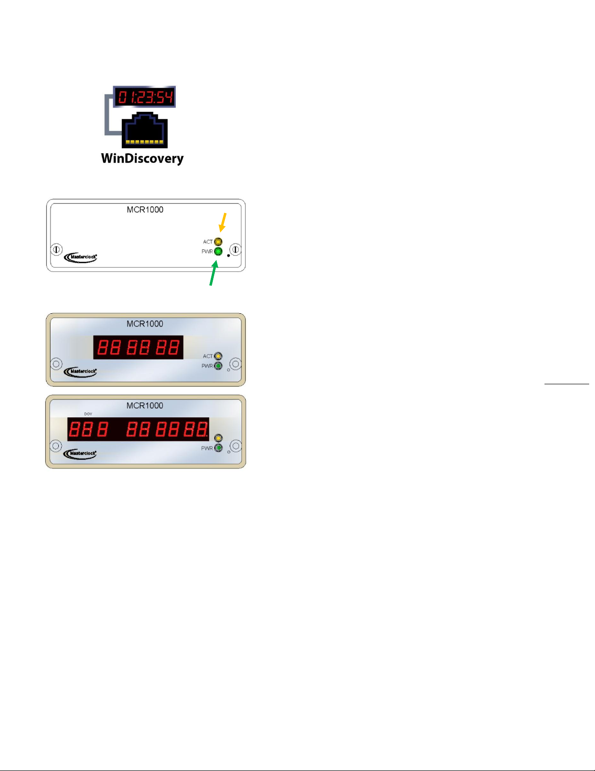
FRONT PANEL ‘LED’ STATUS
All MCR1000 models have two LEDs on the front panel.
The upper amber LED (labeled: ACT for Activity) pulses briefly
and only occasionally with every NTP request.
The lower green LED (labeled: PWR for Power) blinks twice
per second during power up, then once per second after
synching to the external reference.
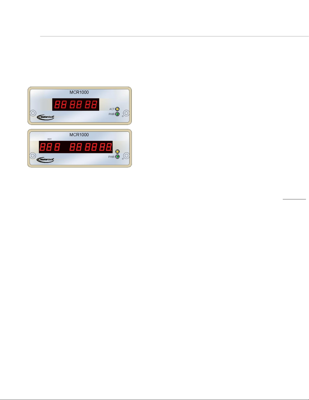
OPTIONAL FRONT PANEL DISPLAYS
Optional front panel displays may be ordered with your
MCR1000 to provide a time or date display. A six-digit LED
shows the current time or date. A nine- digit LED shows the
day of year (doy) and current time or date. See page 8 for
details.
BATTERY BACKED RTC AND TCXO
The MCR1000 maintains its internal time settings in batterybacked memory located on a RTC chip. A Temperature
Compensated Crystal Oscillator (TCXO) provides
freewheeling accuracy (maximum drift) down to ±1 minute
per year (= 165 mS/day).
A built-in battery supplies power, up to 24 hours, to the TCXO
32kHz oscillator and RTC when the unit is powered off. This
allows the internal time to be maintained and the time and
date to increment, whenever power is removed.
The battery is a maintenance-free rechargeable manganese
lithium type. A built-in battery charging circuit is used when
the unit is normally powered, eliminating the need for
maintenance.
Masterclock MCR1000 User Manual – v.2013.08.01
Page 6
6
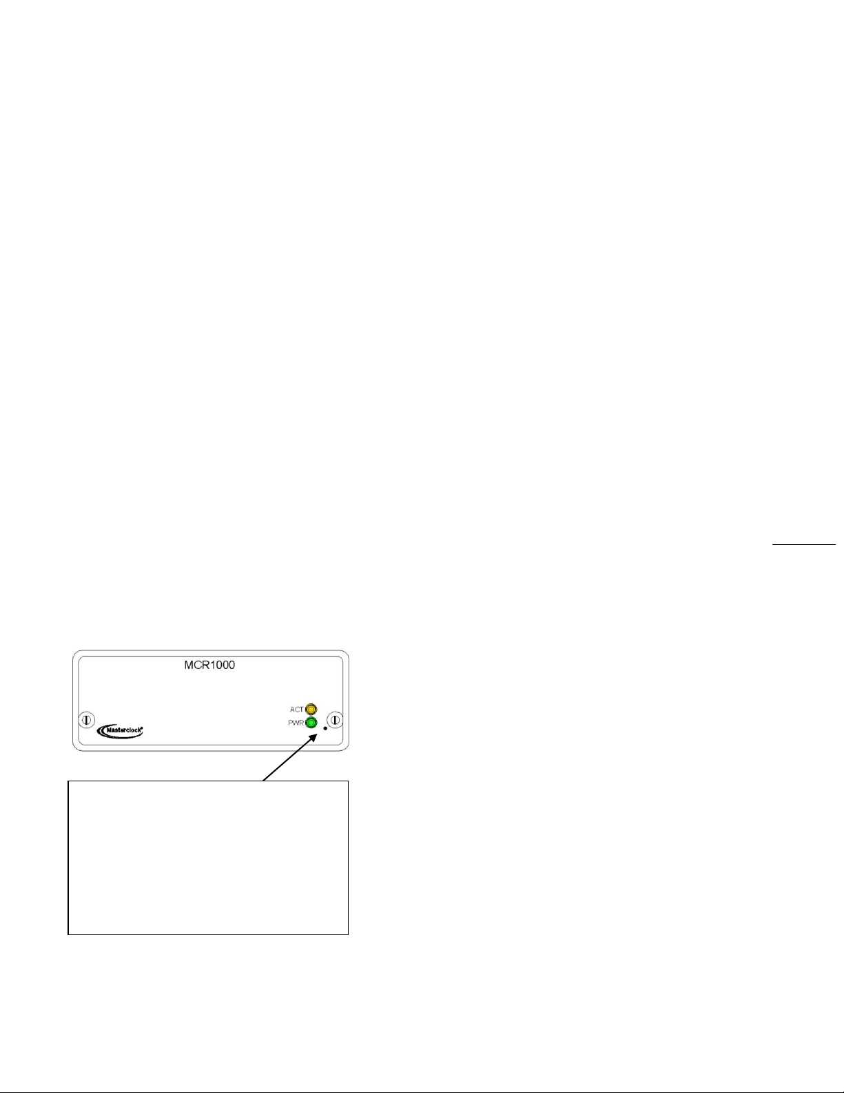
SET TO FACTORY DEFAULT BUTTON ACCESS
HOLE To reset the configuration back to the
factory default insert the end of a paperclip
into the pinhole marked here. Push in to
depress the “Set to factory default” button
inside the unit. Maintain pressure for 5
seconds or until the front panel display goes
to all dashes “- - - - - - “ [if digits are installed].
NON-VOLATILE MEMORY CONFIGURATION
The MCR1000 maintains its configuration parameters
internally in non-volatile memory, even when the power is
off. These configuration settings include the assigned (DHCP
or Static) IP address and network settings, assigned device
name, NTP operational mode, brightness level, assigned
stratum levels, Telnet access, RTC usage validity during
primary reference outages and password. All configuration
parameters (except for the time/date stored in the RTC) may
be reset to the factory default state.
SET TO FACTORY-DEFAULT CONFIGURATION
The MCR1000 is fully tested with factory defaults prior to
shipping. This factory default configuration is defined as:
UTC reference time (no local time zone offset and
daylight saving auto adjustment is disabled)
DHCP configuration mode – enabled
for Network Address and NTP Server addresses
Query (unicast) NTP client mode – enabled
(broadcast/ multicast modes disabled)
Time dissemination via Real-Time Clock (RTC) during
reference outages enabled for 24 hours
Password – set to “public”
Device name – set to MCR1000-XX:XX
(where XX:XX are the last two octets
of the MAC address of the unit)
Relay Schedule – disabled
(relay actuates upon loss of external time reference)
Telnet – enabled
RESET TO FACTORY DEFAULTS
In some situations (such as a lost password or removal of
confidential information, perhaps prior to sending the unit in
for repair service), it may be necessary to return the
MCR1000 to its factory default configuration. The factory
defaults may be restored by using the software interface
method (WinDiscovery or Telnet) or by accessing a recessed
button located in the pinhole on the front panel (see
illustration at left). Insert a paperclip-type wire into the
pinhole and maintain pressure for at least 5 seconds to reset
the unit to factory defaults.
Masterclock MCR1000 User Manual – v.2013.08.01
Page 7

7
TIME CODE INPUT NOTICE
Depending on many factors beyond the
control of MC, the signals that are
received from the Time Code Input
Source are subject to interference, noise,
loading effects and other influences such
as time code format that could cause the
MCR1000 with an installed TCR (Time
Code Reader) option to provide
erroneous time and/or date information
and, under some conditions, could
prevent it from providing time/date
information.
TIME CODE OUTPUT NOTICE
Depending on many factors beyond the
control of MC, the time code signals that
are generated from the MCR1000 with an
installed TCG (time code generator)
option are subject to interference, noise,
loading effects and other influences, such
as a time code format that could affect a
device decoding the time code signal to
provide erroneous time and/or date
information. The time code output of this
device should not be relied upon for
critical timing applications.
GPS INPUT NOTICE
Depending on many factors beyond the
control of Masterclock, the signals that
are received from the GPS satellites are
subject to interference, fading, satellite
failure and other influences that could
cause the MCR1000 with an installed GPS
receiver option to provide erroneous time
and/or date information and, under some
conditions, could prevent it from
providing time/date information.
It is the responsibility of the user to
determine the adequacy and suitability
of this device for the intended use.
Standard Features
• Internal battery-backed Real Time Clock (RTC) retains time
during loss of power or loss of active reference(s)
• Temperature-Compensated Crystal Oscillator (TCXO)
with holdover stability <165mS/day
• Maintenance-free rechargeable battery
• Supports NTP broadcast, multicast, and/or unicast
(query) modes of operation
• Fully configurable network settings: automatic via
DHCP/BOOTP, or Static IP addressing support
• Monitor status and behavior via WinDiscovery app
• Telnet interface for alternate configuration and
maintenance on non–Windows OS networks
• Security features include password protection of
configuration, authenticated communications and the
ability to disable Telnet management access
• UTC time internal reference
• Fully configurable Time Zone, DST and custom time offsets
• Programmable Dry Contact Relay (24VDC, 250mA)
• Single event (daily) programmable relay schedule
• PPS (Pulse Per Second) output TTL level signal which is
locked to the most accurate active time reference
• Front panel power and NTP activity LED status indicators
• USB serial port interface
• R232 serial port interface
• Kinemetrics/Truetime
• NENA 911 PSAP master clock standard
• NMEA 0183 ASCII serial output
• Firmware and function upgradeability
Masterclock MCR1000 User Manual – v.2013.08.01
Page 8
8
Optional Features
Your MCR1000 can support up to three hardware module
accessories and multiple advanced function options. These
make the MCR1000 an extremely versatile network device
and suitable for a large variety of applications.
FRONT PANEL LED DIGITAL TIME DISPLAY
Six-digit time/date display
Nine-digit time display, plus DOY (day of year)
12- or 24-hour time or display in either US
[MMDDYY] or European [DDMMYY] formats
Adjustable brightness control
Display UTC time or local time
NTP SERVER FUNCTION
• Selectable Stratum identification levels (1-15)
• Query, broadcast and multicast modes
• May be operated independent from or
in conjunction with the built-in NTP client
GPS
• GPS Receiver module with 12-channel
parallel/simultaneous receiver
TCR: TIME CODE READER MODULE
• Reads SMPTE 24, 25, 30-fps, non-drop frame,
IRIG-B, 1 kHz amplitude modulated and
pulse width coded (un-modulated)
• Automatic time code detection circuit with
automatic gain adjust
• Single-ended unbalanced or
differential balanced inputs
• Supplied with BNC9-TCI time code input adapter for
SE unbalanced input
• Optional DB9 breakout adapter available for
differential balanced input
• Fully configurable offset for Time Zone and DST
• Programmable delay offset with 1 mS resolution
Masterclock MCR1000 User Manual – v.2013.08.01
Page 9
9
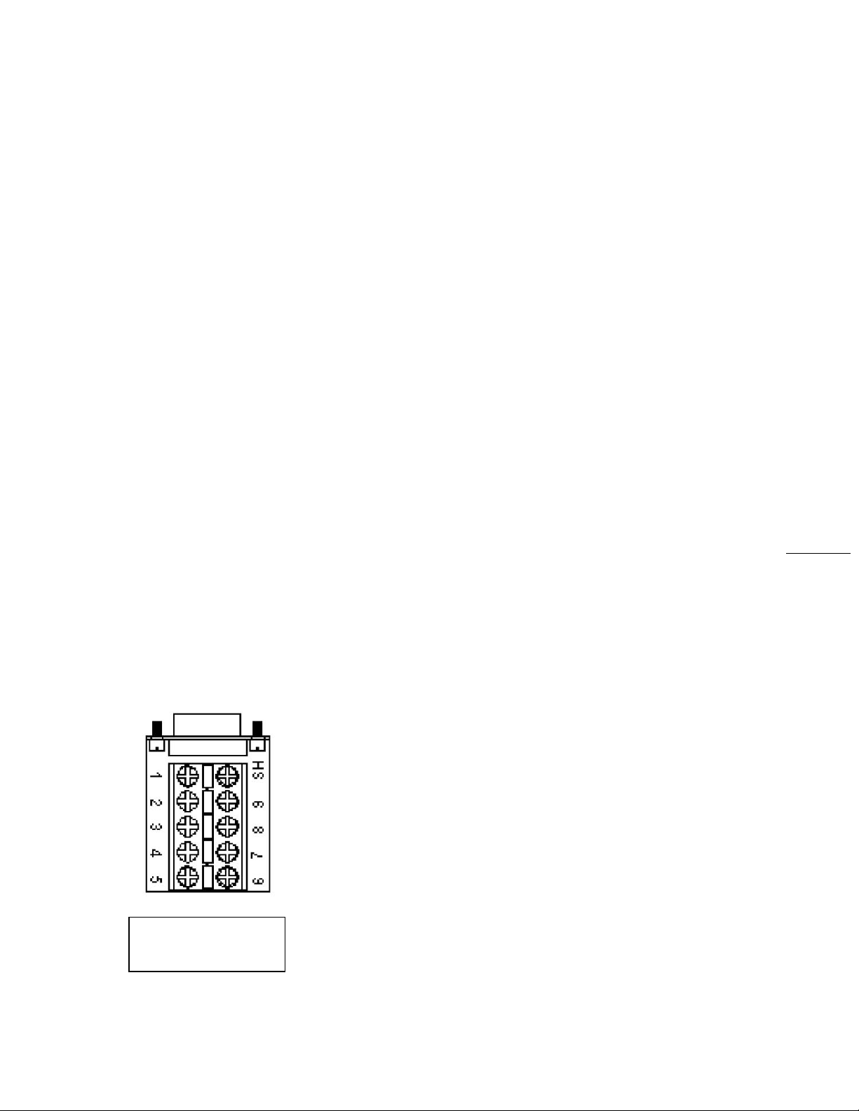
DB9 Breakout Adapter
(item sold separately)
TCR+
ADVANCED TIME CODE READER
• Reads advanced IRIG formats A and E, in addition to
basic IRIG-B and SMPTE
TCG
TIME CODE GENERATOR MODULE
• Generates SMPTE 24, 25, 30-fps, non-drop frame,
IRIG-B, 1 kHz, amplitude modulated and pulse width
coded (unmodulated)
• Single-ended unbalanced output
• Fully configurable offset for Time Zone and DST
• Programmable delay offset with 1 mS resolution
TCG+
ADVANCED TIME CODE GENERATOR
• Generates advanced IRIG formats A and E in
addition to basic IRIG-B and SMPTE
HSO: HIGH STABILITY OSCILLATOR
• Internal Oven Controlled Crystal Oscillator (OCXO)
provides high stability time reference of
<250 mS /year drift while freewheeling after
disciplining from a GPS or other accurate reference
• Calibrates or locks to best “active” time source –
use GPS option for maximum holdover stability
• 10 MHz sine wave frequency reference output
(requires HS option)
PPO: PROGRAMMABLE PULSE OUTPUT
• Pulse interval and duration can be selected via
software from 100 μseconds to 3 days
• Default is 1PPM (pulse per minute)
• Pulse output is 5Vpp from a low impedance source
• Pulse width selectable from 10 μS to 100mS
• Accuracy is the same as the current reference
source, whether GPS, Time Code or NTP
DB9 BREAKOUT ADAPTER
• For full I/O (input /output) signal access
Masterclock MCR1000 User Manual – v.2013.08.01
Page 10
10
Configuration, Passwords, UTC and DST
WinDiscovery permits remote network device detection,
configuration and management of Masterclock brand
network devices from Windows-based PCs. This is your
primary detection, configuration and maintenance software.
See page 22.
TELNET INTERFACE – FOR UNIX AND LINUX
A Telnet terminal-style command line interface is used on
networks that are not Windows-based (i.e. Linux and Unix).
The Telnet interface may be disabled. See page 34.
PASSWORD PROTECTION
The MCR1000 is provided with a password as a security
access feature. Each Masterclock network device requires a
password that must be entered before the device will accept
configuration changes. Each device, or set of devices, can
have a unique password or they can all share the same one.
The password can be changed and retained to permit access
only to authorized users.
A password can be a maximum of 11 characters and may
contain any sequence of letters, numbers, and common
punctuation. Passwords are case-sensitive.
DEFAULT PASSWORD
The factory default password is “public”
UTC/GREENWICH MEAN TIME REFERENCE
The MCR1000 reference time is based on UTC (Coordinated
Universal Time). UTC is the local time at the prime reference
meridian at Greenwich, England. At a given location on the
planet, local time can be displaced (referenced to UTC) by -11
to +12 hours. The NTP time distribution standard operates
with UTC-reference time only. All offsets for time
displacements are input at the final stage (e.g. for computers
and clocks). Otherwise a double offset might occur.
UTC is sometimes colloquially referred to as "Greenwich
Mean Time" (abbreviated GMT).
Masterclock MCR1000 User Manual – v.2013.08.01
Page 11

11
TIME ZONE OFFSETS
A time zone offset (or bias) can be provided to adjust the
time for display or time output purposes. A bias can be set as
a positive (+) or negative (-) value with a resolution of one
second. Factory default: No offset = UTC time.
DAYLIGHT SAVINGS TIME
Daylight savings time (aka: “Summer Time” in Europe)
adjustments can be configured separately and in addition to a
Time Zone offset.
Daylight time standards vary widely throughout the world.
Traditional daylight/summer time is configured as a one-hour
positive bias. The new US/Canada DST standard is: one-hour
positive bias, starting at 2:00 am on the second Sunday in
March, and ending at 2:00 am on the first Sunday in
November.
In the European Union, time changes are defined relative to
the UTC time of day instead of local time of day (as in US).
To ensure proper hands-free year-around operation, the
automatic daylight time adjustments must be configured
using the Daylight Savings Time Option and not with the
Time Zone offset option.
Factory default: Daylight Savings time is not set.
LEAP SECONDS
UTC runs at the rate of atomic clocks. When the difference
between this official time and one based on the rotation of
the Earth approaches one second, a "leap second" is added to
UTC.
This has virtually nothing to do with the ongoing gradual
slowing of the Earth’s rotation over millions of years, which
occurs at a much slower rate.
Masterclock MCR1000 User Manual – v.2013.08.01
Page 12

12
Option
No.
Comments
Time Offset
2
The value provided will be used for the time zone offset configuration, unless
it is defined as zero in which case it will be ignored and the MCR will rely on
internal configuration. Note: This option does not provide information
appropriate for dynamic Daylight Savings Time use.
Router
3
The first IP address provided will be used for router/gateway configuration.
Domain Name
Server
6
Up to two server IP addresses may be specified. NTD clock will treat
addresses as primary and secondary DNS servers.
Network Time
Protocol Server
42
Up to two server IP addresses may be specified. NTD clock will treat
addresses as primary and secondary NTP servers.
Important Note:
Long DHCP names are not supported.
Only the first 14 characters of the
device name will be registered by the
DHCP server.
The IP address of the unit is required to
configure the MCR1000 with Telnet.
The DHCP server can be utilized to
provide the IP address of the associated
device name that is registered.
Important Note:
An MCR1000 network device will not
function properly if configured to use
DHCP services when no DHCP server is
present on the network. An MCR1000
network device will default to a fallback
IP address of 169.254.X.Y when no
DHCP server is available on the
network, where X and Y are random.
DHCP/BOOTP AUTO-CONFIGURATION
The MCR1000 can obtain its network configuration
automatically from DHCP or B OOTP, when one or the other is
available on the network. Utilizing DHCP/BOOTP, the
MCR1000 will automatically be assigned its network
configuration. This includes an IP address and additional
functions, such as DNS server and Router/Gateway settings.
This feature is enabled by default.
DHCP (Dynamic Host Configuration Protocol) is a mechanism
for automating the configuration of networked devices that
use TCP/IP. When DHCP is enabled, DHCP configuration
acquisition will overwrite any manual configuration items.
BOOTP is a precursor to DHCP. The MCR5000 can obtain
configuration from a BOOTP server when DHCP is absent.
The MCR1000 can automatically obtain Time Zone Offset
configuration and the NTP server addresses (primary and
secondary). To utilize these features the DHCP server of the
network must be pre-configured with the appropriate
checklist items (see below). Factory default: DHCP enabled.
The following RFC2132-defined optional configuration items
are, when available, used by the MCR1000 for configuration:
Masterclock MCR1000 User Manual – v.2013.08.01
Page 13
13
Rename the device here
Reset the network configuration
by hand here
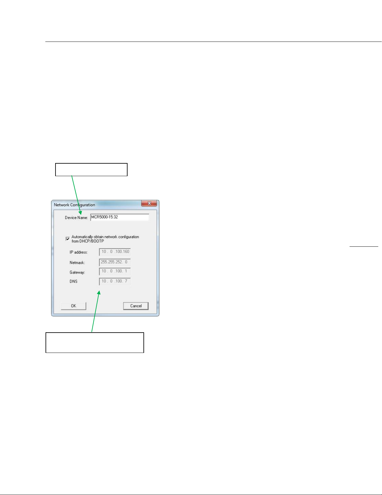
DEVICE NAME/DHCP NAME REGISTRATION
All Masterclock network appliances should be provided with
custom device names relating to your own organizational
requirements. It is recommended that a robust naming
scheme (perhaps based on location) be developed before
devices are installed on a campus or throughout a building.
BY DEFAULT: Device names are the product name
abbreviation followed by the last octet of the device’s
Ethernet address (MAC address).
The device name may be changed from the factory default
name by entering a unique name of up to 32 characters.
If a DHCP server is available on the network when the
MCR1000 is installed, the unit will be auto-registered with the
DHCP server. The network system administrator can then
view this DHCP name registration and the currently assigned
IP address at the DHCP server.
STATIC IP CONFIGURATION
The MCR1000 allows for Static IP address, Gateway and DNS,
network configuration entries to be made manually if no
DHCP/BOOTP server is available. In addition, the NTP server
addresses can be adjusted manually. Manual configuration
requires disabling the DHCP defaults via WinDiscovery (or
other configuration app).
NTP (NETWORK TIME PROTOCOL)
NTP is an open-standard time synchronization protocol
designed for precision synchronization and maintenance of
time/date on computers and other devices attached to
TCP/IP networks. NTP itself is transported with the UDP/IP
(User Datagram Protocol), and is usually served on port 123.
NTP time/date is UTC-referenced, as the protocol has no
provisions for representing Time Zones or Daylight Savings
Time (“Summer Time” in Europe).
A wealth of useful NTP information and resources can be
found at
http://www.ntp.org
Masterclock MCR1000 User Manual – v.2013.08.01
Page 14

14
Note: Use of the multicast addressing
method requires the use of routers &
switches and other network devices
that support the Internet Group
Management Protocol (IGMP). In
addition, the IGMP mode must be
enabled and configured for multicasting
addressing to be implemented
properly. The implementation of
multicasting addressing is beyond the
scope of support available from
Masterclock. Please ensure that your
network system components are
capable of (and configured properly
for) IGMP before utilizing the multicast
addressing feature.
Note: You will need to check with your
firewall vendor to determine how to
enable multicast traffic through a
firewall. In addition you may want to
read:
RFC 2588: IP Multicast and Firewalls.
NTP CLIENT
The MCR1000 acquires its internal UTC time reference from
an NTP timeserver by using a built-in NTP client. The NTP
client is fully configurable and can operate in several NTP
modes to reference both a primary and a secondary NTP
server. The NTP client can be disabled to allow operation as a
stand-alone unit without a network connection.
NTP SERVER OPTION
The MCR1000 can also act as a NTP server with the
installation of the NTP Server Option. This option is fully
configurable and can operate in several NTP modes. See the
optional features section (page 11) for more information.
Warning: If NTP Server is enabled and an offset is created for
it, then NTP client must be disabled, else the NTP time served
will be erroneous.
NTP ADDRESSING MODES
UNICAST - The MCR1000 supports the unicast method of NTP
packets transfer. Unicast method involves direct transfer
of requested information from the NTP server to the NTP
client based on a query or NTP time request. The unicast
method is supported simultaneously when either the
broadcast or multicast modes are selected.
BROADCAST - The MCR1000 supports the broadcasting of
NTP packets. This feature is useful in situations where
network administration may wish to avoid the network
traffic created by a large number of clients making
periodic NTP requests, or in situations where such
periodic requests end up synchronized is such a manner
as to exceed the MCR1000’s ability to reply. The
broadcast mode is a widespread or open-ended
broadcast, not intended for any specific IP address.
The MCR1000 provides NTP (UDP) broadcasts using the
broadcast address [255.255.255.255].
Note: Some firewalls and routers will not forward UDP
broadcasts by default. Security configurations may need
to be adjusted to allow the UDP broadcast packets to
pass on the configured port.
MULTICAST - The MCR1000 also supports multicast
addressing of NTP packets as a recently added feature.
As opposed to broadcast mode (see above), data is sent
to every possible receiver (client). Multicasting is useful
because it conserves bandwidth. It does this by
replicating packets only as needed within the network. It
sends packets only to receivers (clients) that want them.
Masterclock MCR1000 User Manual – v.2013.08.01
Page 15

15
THE CONCEPT OF A GROUP
IS CRUCIAL TO MULTICASTING
Every multicast requires a multicast group. The sender (or
source) transmits to the group address, and only members of
the group can receive the multicast data. A group is defined
by a Class D address.
The MCR1000 does not restrict the use of the multicast
address assignment and supports the full range of Class D
multicast addresses or groups from 224.0.0.0 to
239.255.255.255. These address ranges for multicasting are
defined and governed by RFC3171, IANA IPv4 Multicast
Guidelines.
Typically, the multicast address range is from
224.0.1.0 to 224.0.1.255.
The multicast address range from 224.0.1 to 224.0.24 is
considered the INTERNET WORK CONTROL BLOCK. This
address range is utilized for NTP traffic. Please refer to the
RFC3171 for your specific application and implementation.
http://www.rfc-editor.org/rfc/rfc3171.txt
The Internet Group Management Protocol (IGMP) is a
protocol that controls group membership for individual hosts.
This protocol only operates in a LAN setting, but is required if
you wish to be able to join a multicast group on a host.
IGMP is defined in RFC 2236.
http://www.ietf.org/rfc/rfc2236.txt
ANYCAST - The MCR1000 does not currently provide anycast
capability.
For more information on How to Listen for NTP
see page 32.
Masterclock MCR1000 User Manual – v.2013.08.01
Page 16
16
CAUTION: Connecting input voltages or switching
currents beyond the maximum ratings for the
relay (up to 24VDC/VAC, 250 mA max) could
damage the MCR1000. Such damage is not
covered under your warranty.
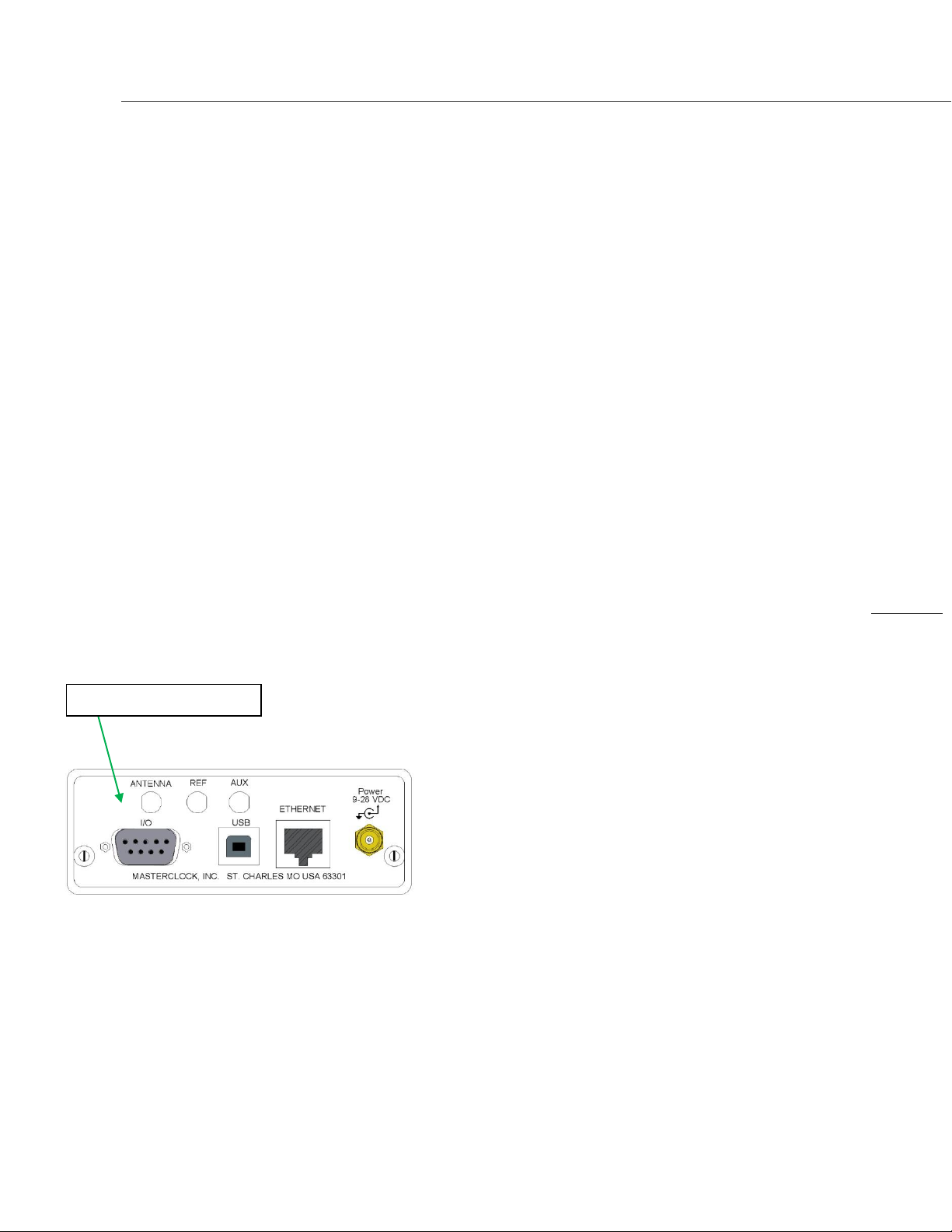
SERIAL PORT INTERFACE
Back Panel Interfaces
RELAY AND PROGRAMMABLE RELAY EVENT
The MCR1000 includes a low voltage dry contact 24V AC or
DC relay that can be configured with an internal jumper to be
either NO (normally open) or NC (normally closed) using the
terminal block connector on the rear of the unit.
Factory default: Jump for NO (normally open).
The relay can provide two mutually exclusive functions.
1. By default: The relay will actuate to indicate when the
unit has lost synchronization (lock) with the external time
reference.
2. The relay can be programmed to actuate at a single time
(defined as HH:MM:SS start time) for a specified duration
(in seconds) once per day.
Please refer to the specifications section (p. 47) for the
maximum relay ratings.
PPS (PULSE PER SECOND) OUTPUT
The MCR1000 provides a PPS output. PPS is commonly used
as an on-time mark for timing and synchronizing systems.
The PPS is a 5V TTL (Transistor-Transistor Logic) level signal
that is locked to the currently selected and most accurate
time reference (external or internal). The rising edge of the
PPS signal provides the “On Time” mark. The PPS output is
available on the shared I/O connector (Serial Port Interface)
on the rear of the unit.
SERIAL PORT INTERFACE
The MCR1000 provides both an RS-232 null modem and USBtype B serial interface for serial communications and
configuration. These communications include NENA 911,
NMEA 0183 and Kinemetrics/Truetime.
Masterclock MCR1000 User Manual – v.2013.08.01
Page 17
17
CHECKLIST
Dynamic Networking Configuration
(default for all MCR1000 devices)
__ Confirm that a DHCP/BOOTP service
is accessible on the local network
__ Determine if DHCP server will
provide NTP server configuration
__ Determine if DHCP server will
provide time zone configuration
-- OR --
Static Networking Configuration
__ IP address and netmask designation
for device
__ Primary and secondary DNS
(domain name) servers
__ Gateway/router
__ Primary and secondary NTP time
sources
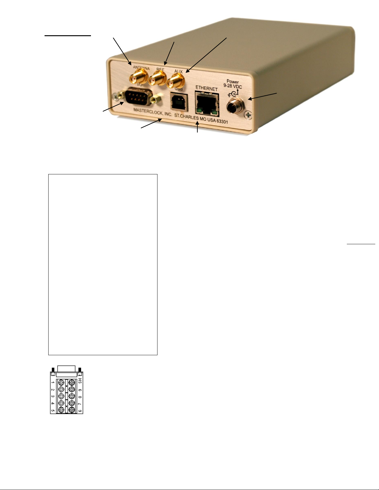
I/O
DB9 Male
RS232
PPS
Time Code input/output
NO relay
GND REF
OPTIONAL
Antenna
SMA female
GPS
OPTIONAL
REF
SMA female
10MHz Sinewave
OPTIONAL
AUX
SMA female
DC INPUT
Locking 2 mm jack
ETHERNET RJ45
10/100 MB
NTP
USB B
DB9 Breakout Adaptor
Installation
PRE-INSTALLATION CHECKLIST
The MCR1000 is a network device with an NTP client enabled
and configured for DHCP provided network settings and NTP
server addresses (by default). Other settings are available.
Before installing an MCR1000 on a network one should be
prepared with the following basic configuration information
(see box at left). You may need to ask your network
administrator for these numbers and information.
QUICK START INSTRUCTIONS
Make all connections at the rear of the unit, but keep the
power disconnected until the last step.
Connect the MCR1000 device to your LAN (Local Area
Network) hub/router/switch using Cat5 cable making the
connection to the RJ45 connector labeled “ETHERNET”
Make any additional desired input and output
connections to the DB9 connector labeled “I/O” using
either your own cable or an optional DB9 breakout
adapter (item sold separately by Masterclock)
Insert the WinDiscovery CD into a computer running
Windows 2000, XP, 7, Server 2003 or Server 2008 SP-1.
The InstallShield application will begin automatically if
AutoRun is enabled on your system. Otherwise, browse
to the CD root directly and click the setup.exe file to
begin the installer.
Apply power by inserting the supplied AC:DC power
supply module into an appropriate AC power source and
the DC power connector into the male Switchcraft-style
locking power socket on the rear of the unit (labeled
Power 9-28VDC).
Masterclock MCR1000 User Manual – v.2013.08.01
Page 18
18
Note: when configured to obtain network
configuration through DHCP, the display may
hesitate on startup while DHCP is resolved.
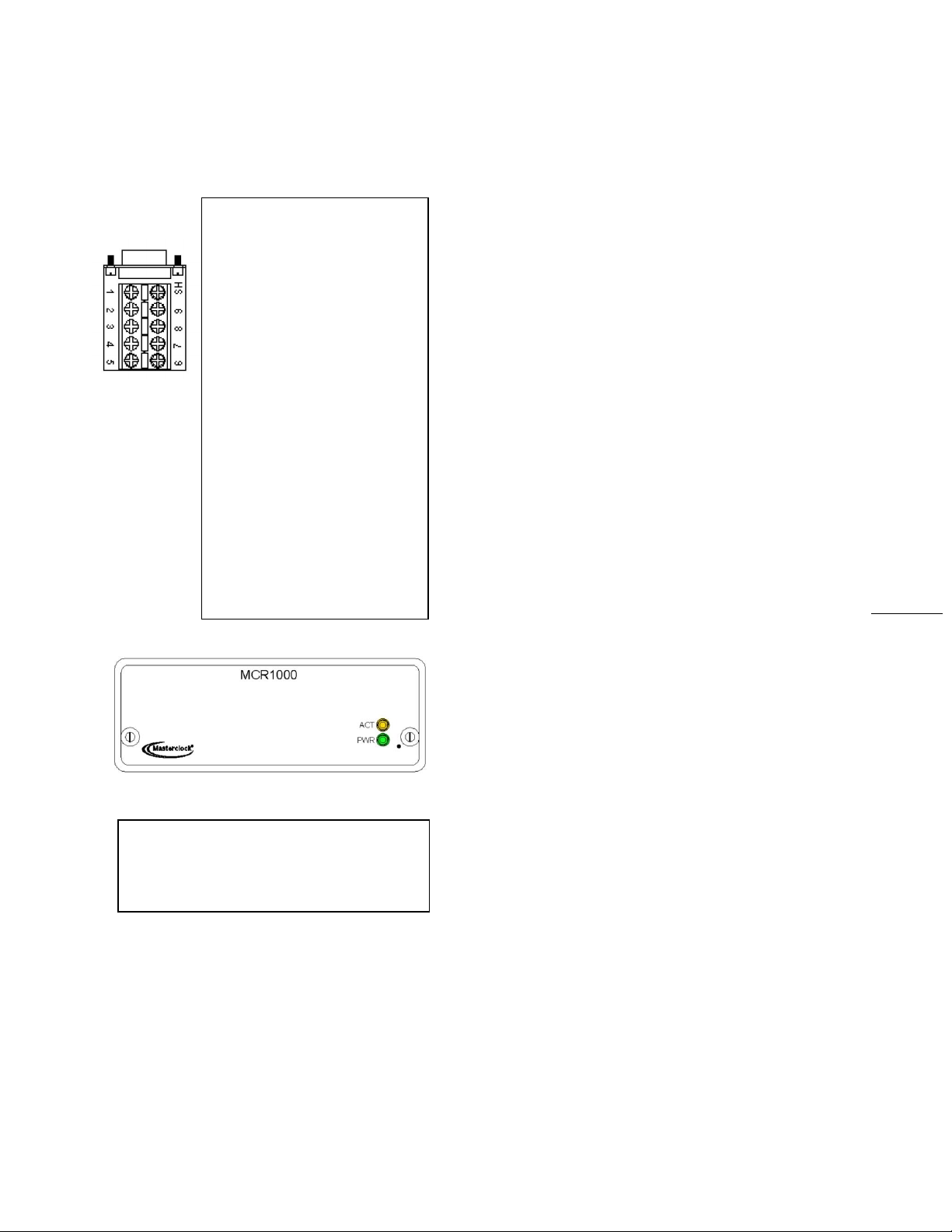
Standard I/O connections using
optional DB9 Breakout Adapter
1 - PPS
2 - RS232TX
3 - RS232 RX
4 - Relay Common
5 - Ground/Reference
6 - Time Code Output
7- Time Code IN +
*8- Time Code IN -
9 - Relay Contact
*If an unbalanced signal is
desired, pin 8 should be tied to
ground.
Please refer to the options
sections of this user manual for
making connections or
configuring any installed
options.
If desired the unit can be operated from a nominal
12- VDC supply such as a battery (9-28 VDC range).
Caution: Observe voltage polarity as indicated on the
rear panel. The center pin is positive +VDC, and is
labeled 9 -28VDC.
• Monitor the front panel for power up status.
When power is first applied the initial sequence of
the front panel LEDs are:
Front panel PWR and ACT indicators will be off, but
after about 30 to 40 seconds…
Units with 6-digit or 9-digit LEDs will show all dashes
followed by all 8s, then all LEDs extinguish briefly
before displaying time
Amber (ACT) LED signifying NTP status: Off
Green (PWR) LED: Blinks twice per second, with
numerals incrementing each second. This indicates
lock to internal TCXO oscillator and acquiring lock to
an external source, if applicable.
Green (PWR) LED: Blinks once per second. This
indicates synchronization to an external reference
CONFIGURE THE MCR1000
USING YOUR PREFERRED METHOD
At this time, the MCR1000 can communicate with
WinDiscovery, which can detect and identify the
MCR1000 through the exchange of broadcast messages,
even when TCP/IP networking parameters are not
configured on the same network.
Once the MCR1000 has a valid network configuration
and the IP address of the unit is known, it can also be
accessed and configured via Telnet by computers in the
same network.
Masterclock MCR1000 User Manual – v.2013.08.01
Page 19
19
WinDiscovery Installation and Operation
Included on CD with your MCR1000 is the WinDiscovery
software application for detection, configuration and
management of all your NTP devices from Masterclock.
The application operates in the Microsoft Windows OS.
INSTALLING WINDISCOVERY
If you haven’t already done so, insert the CD that shipped
with your MCR1000 to automatically install WinDiscovery. If
AutoRun is not enabled on your computer:
1. Run the “setup.exe” application from the CD.
2. By default, the setup utility will suggest installing files to
C:\Program Files\Masterclock\WinDiscovery.
3. Click the [OKAY] button.
USING WINDISCOVERY
Open WinDiscovery from the “Start Menu” or by double-
clicking the shortcut icon on the desktop.
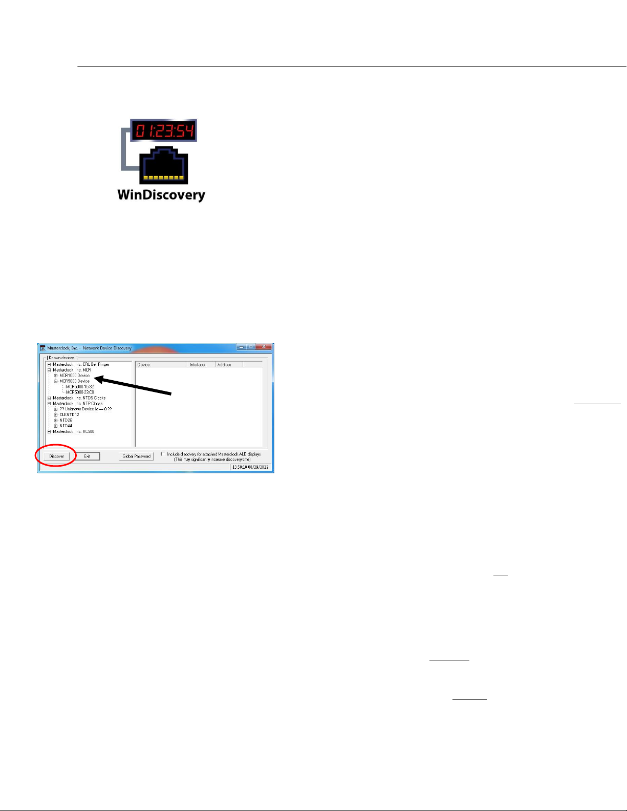
Click the [Discover] button to reveal all the devices accessible
on the network. The status bar will display the count of
devices found. When complete (please wait until ‘100%’
appears then disappears), a list of device families and groups
will be displayed in the left pane of the WinDiscovery
window. Click the [+] buttons to reveal the individual devices.
Click the [-] buttons to hide them.
Each device is configured with a device name from the
factory. Each device name includes the model name and a
MAC address extension.
You should change the device name to one that can identify
the location of the device.
It is highly recommended that only one user opens
WinDiscovery at a time. Other methods should not be used
to manage the network devices while using this app.
MENU
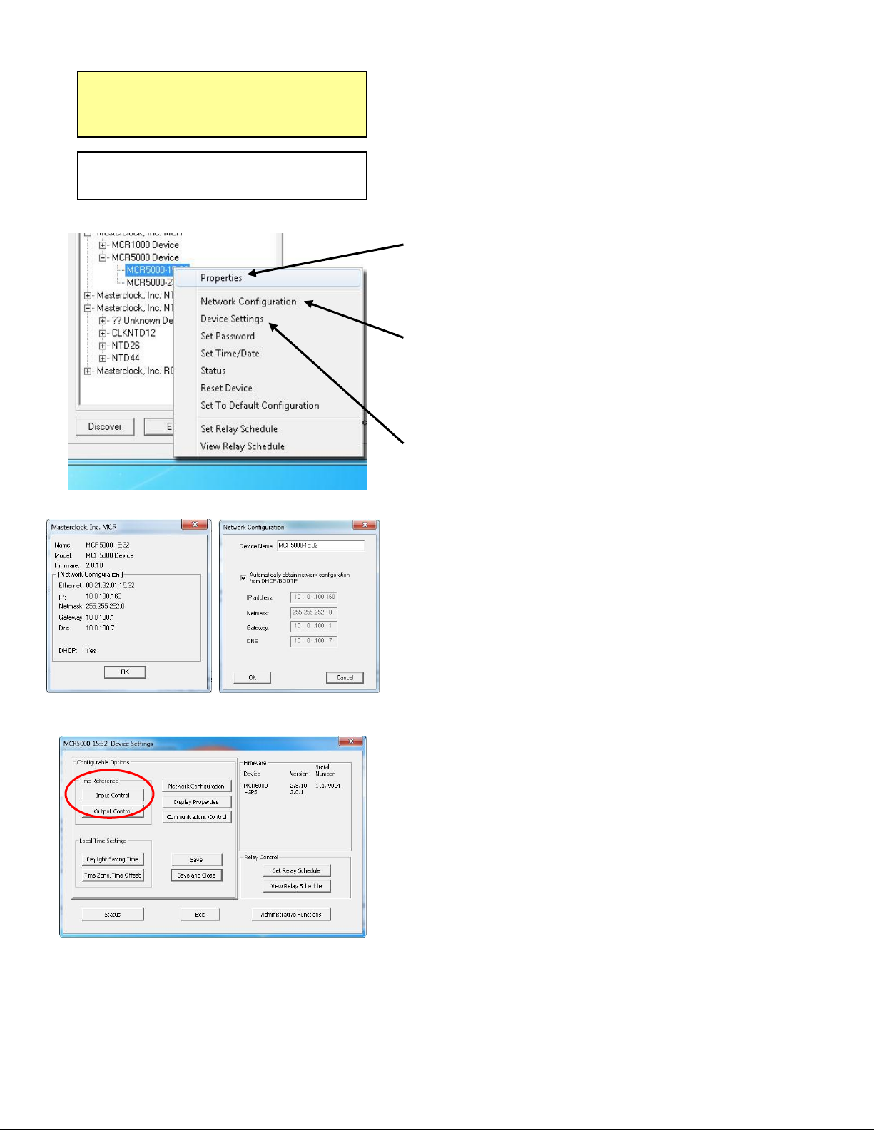
To open a Menu of Options window, including
Properties and Device Settings, right click the device name.
Or
To open the Device Settings window, left click the device
name.
Both options will be covered in the following instructions.
Masterclock MCR1000 User Manual – v.2013.08.01
Page 20
20
Below: This menu appears following a right
click to the device name.
Properties Network Configuration
Device Settings – Input Control is circled
Note: Images here were pulled from a
MCR5000 WinDiscovery connection. The
MCR1000 is essentially the same.
INSIDE THE MENU OF OPTIONS WINDOW:
Click your choice (see below) to open the window for that
function.
PROPERTIES
The device properties (lower far left) may be viewed in
summary by clicking the [Properties] button.
NETWORK CONFIGURATION
The network configuration (lower near left) may be viewed in
summary by clicking the [Network Configuration] button.
DEVICE SETTINGS (DS)
The Device Settings window (lower left) configures the
MCR1000 to receive and display in the format that you
prefer, using Time Zone offsets and DST settings to
completely customize it relative to UTC time.
The top right section of the “Device Settings” window shows
a list of the firmware and options associated with your
MCR1000.
The rest of the “Device Settings” window includes access to
all configuration options for the network. These include time
reference inputs and outputs, display properties, relay
control and administrative functions, such as password. There
is also a status display to monitor remote clocks and devices
from your computer screen using the free, included
WinDiscovery software application.
Any changes made in this window, including all the buttons
thereon, will not be applied until you click the [Save] button,
or the [Save and Close] button, prior to clicking the [Exit]
button.
DS > INPUT CONTROL (IC)
The [Input Control] button provides access to the “Input
Control” window, which provides buttons for NTP Client,
Time Code Reader, NMEA Client and NENA Client.
Masterclock MCR1000 User Manual – v.2013.08.01
Page 21
21
Note: Some NTP/SNTP clients will
expect NTP servers to operate on port
123 and cannot be configured to
utilize alternate ports.
DS > IC > NTP CLIENT
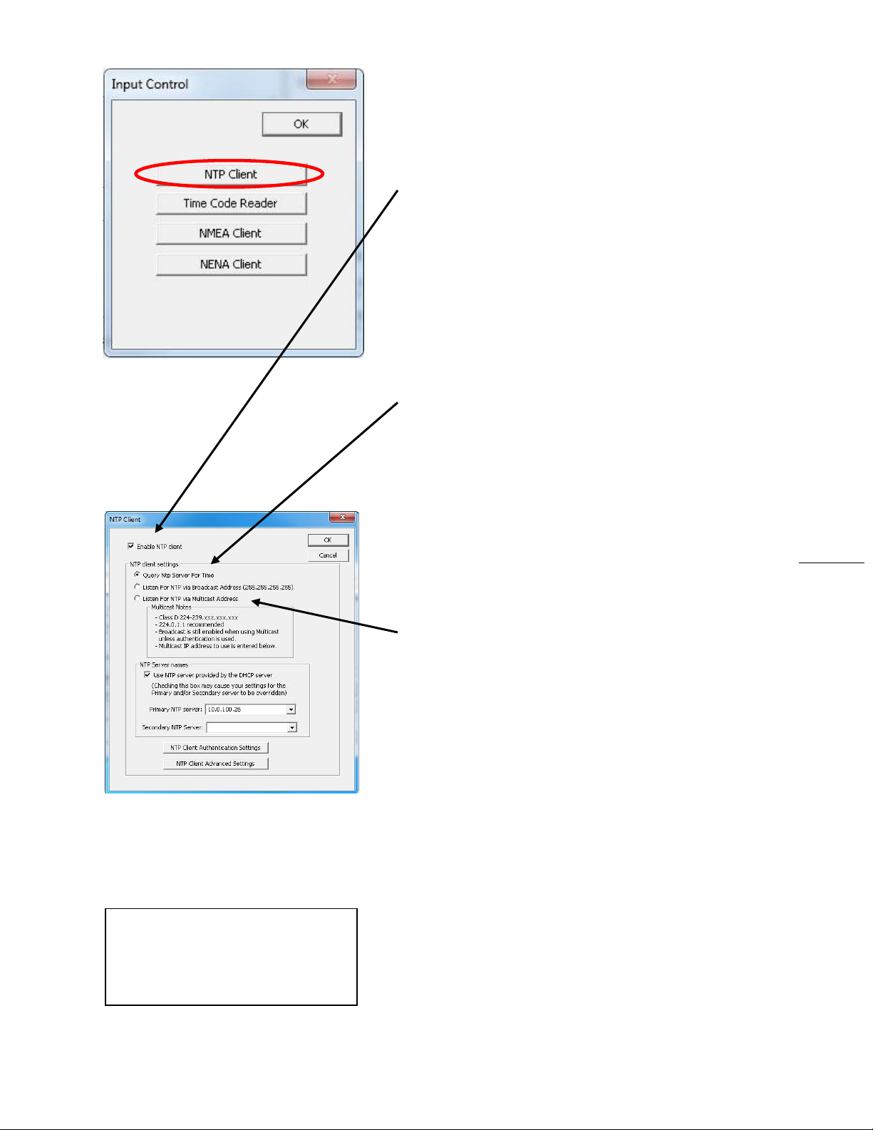
While on the “Input Control” window, click the [NTP Client]
button to access settings for the NTP client.
ENABLE NTP CLIENT – is enabled by default. However, it may
be desirable to disable the NTP client for certain
applications, such as those in which the MCR1000 will
not reside on a network during typical operation.
Deselect “Enable NTP client” if desired.
The network client can be configured to either query the
NTP time server at a selected interval, to listen to NTP
broadcasts only, or to listen to multicast broadcasts.
NTP CLIENT SETTINGS
QUERY NTP SERVER FOR TIME – is enabled by default. This is
the unicast mode. The default configuration is to query
the NTP server at 10-second intervals.
LISTEN FOR NTP VIA BROADCAST ADDRESS – The MCR1000
can be configured to listen to NTP broadcasts by
selecting the “Listen for NTP via broadcast address
[255,255,255,255]” checkbox. When this is selected, the
broadcast timeout period (in seconds) is adjustable. To
configure the device to only listen to NTP broadcasts,
click the checkbox [Listen for NTP broadcasts only] and
enter a “Broadcast/ Multicast Timeout” in seconds. The
default timeout is 3600 seconds (1 hour).
LISTEN FOR NTP VIA MULTICAST ADDRESS – The MCR1000
can be set up to listen to NTP using multicast addressing
by selecting the “Listen for NTP via multicast address”
checkbox. When multicast mode is selected, the client
will also listen to broadcast messages.
When enabled, the Multicast Class D/Group Address
may be specified as well as the frequency that multicast
broadcasts will be issued. This can be changed as desired.
The NTP client can listen for NTP multicast broadcasts
using the full Class D/Group Address range. The NTP
client does not restrict the use of the multicast address
assignment and supports the full range of Class D
multicast addresses or groups from 224.0.0.0 to
239.255.255.255.
These group addresses are defined and governed by
RFC3171, IANA IPv4Multicast Guidelines.
Typically, the multicast address range 224.0.1.0 to
224.0.1.255 is utilized for NTP traffic. Please refer to the
RFC3171 for your specific application.
http://www.rfc-editor.org/rfc/rfc3171.txt
Masterclock MCR1000 User Manual – v.2013.08.01
Page 22
22
NTP SERVER NAMES (see page 21) – By default the [Use NTP
server provided by the DHCP server] box is checked and
a primary NTP server address is displayed. If you wish to
uncheck the box and provide your own server addresses
for both primary and secondary servers, do so here.
NTP CLIENT AUTHENTICATION SETTINGS – This window
permits the entering of up to 15 MD5 key values to be
trusted or allowed. Primary client settings permit the
entry of a primary server key number, a secondary server
key number and a broadcast key number.
NTP ADVANCED SETTINGS – Advanced settings allow for the
adjustment of additional network communication
settings. Under most typical operating circumstances it is
not necessary, nor is it suggested, to change the
advanced settings options.
DS > IC > TIME CODE READER
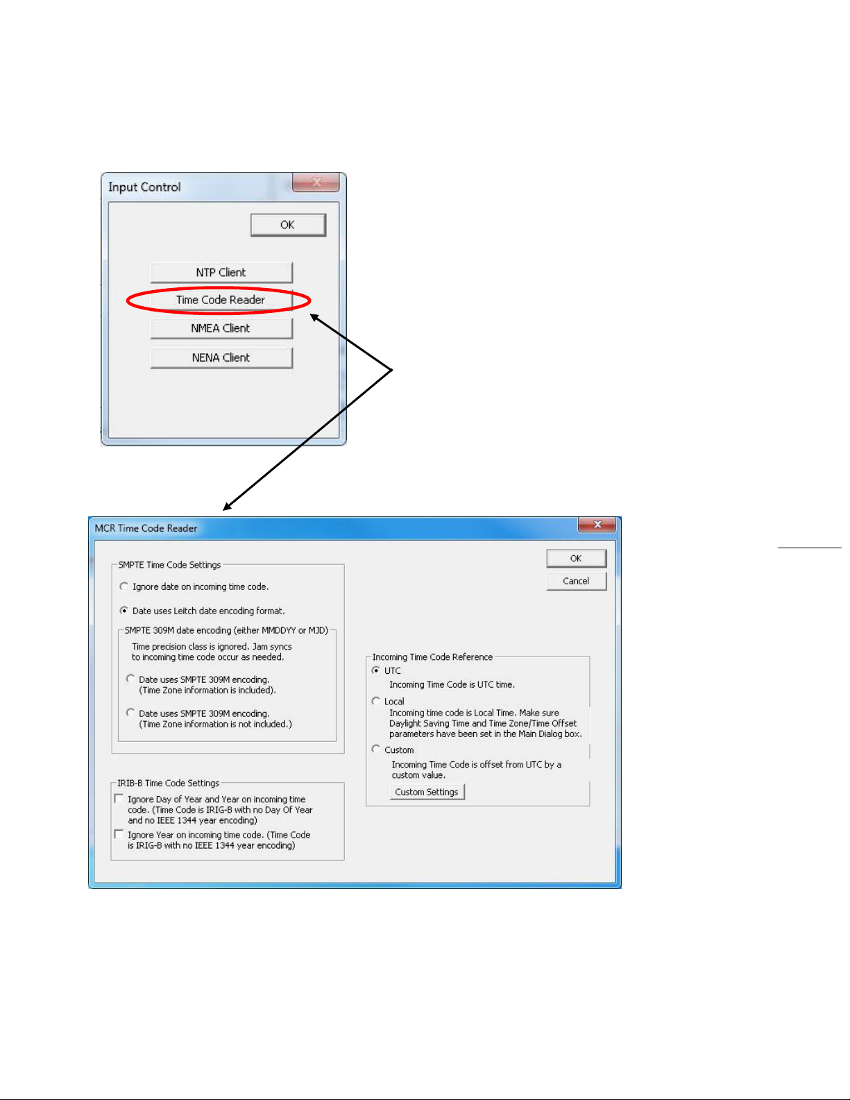
The [Time Code Reader] button opens the “MCR Time Code
Reader” window and will only operate when a Time Code
reader is networked. Choose from the selections offered at
lower left and click the [OK] button when complete.
Masterclock MCR1000 User Manual – v.2013.08.01
Page 23
23
DS > IC > NMEA CLIENT
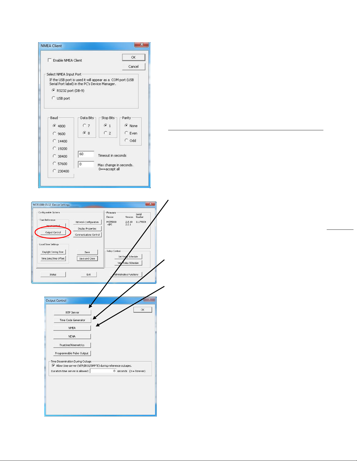
Click the [Enable NMEA Client] button (see page 22) to adjust
the “Port, Baud rate, Data bits, Stop bits, Parity, Time out
and Maximum change for NMEA in seconds” selections.
DS > IC > NENA CLIENT
Click the [Enable NENA Client] button (see page 22) to adjust
the “Port, Baud rate, Data bits, Stop bits, Parity, Time out
and Maximum change for NENA in seconds” selections. Yes,
the NENA window is virtually identical to the NMEA window.
DS > OUTPUT CONTROL (OC)
On the Display Settings window (left) click the [Output
Control] button to access the MCR1000 output options (see
below). As before, any changes made in this window will not
be applied until you click the [Save] button, or the [Save and
Close] button on the “Device Settings” window.
DS > OC > NTP SERVER - By default the [Enable NTP Server]
button is checked with all appropriate settings filled in. If
you want to change these settings, uncheck the box.
Stratum levels can be modified. By clicking the NTP
Server Authentication Settings button you can set MD5
key settings for both Client and Server, plus enable
authentication for client request, broadcast and
multicast packets.
DS > OC > TIME CODE GENERATOR – This button operates
only when a Time Code device is on the network. See
page 35 for a sample of this window.
DS > OC > NMEA - The MCR1000 provides an NMEA
(National Marine Electronics Association) 0183 message
output on the RS232 serial port. All MCR1000 units
transmit the simple ZDA format NMEA message as it
contains only time and date updates.
NMEA Message Output – is disabled by default.
Select the RS232 settings button to adjust the baud rate
and communications settings for the MCR1000 window.
The RS232 port can be configured for baud rates of 4800,
9600, 19200, 38400, and 57600; along with 7 or 8 data
bits, 1 or 2 stop bits, and the parity bits can be selected
as None, Odd, and Even The default settings will be 4800
baud, 8 data bits, no parity, 1 stop bit.
The NMEA messages may be monitored on a computer
using HyperTerminal or PuTTY or the output may be
connected to other devices or apps that accept NMEA
0183 messages.
Masterclock MCR1000 User Manual – v.2013.08.01
Page 24
24
Input and Output NMEA with GPS
The MCR1000 may be configured with the NMEA 0183 option
for communication between marine electronic devices such
as an echo sounder, sonar, gyrocompass, autopilot and GPS,
among other instruments.
The MCR1000 will use any one of the following NEMA
messages for time synchronization.
$GP ZDA
$GP RMC
$GP GGA
$GP GLL
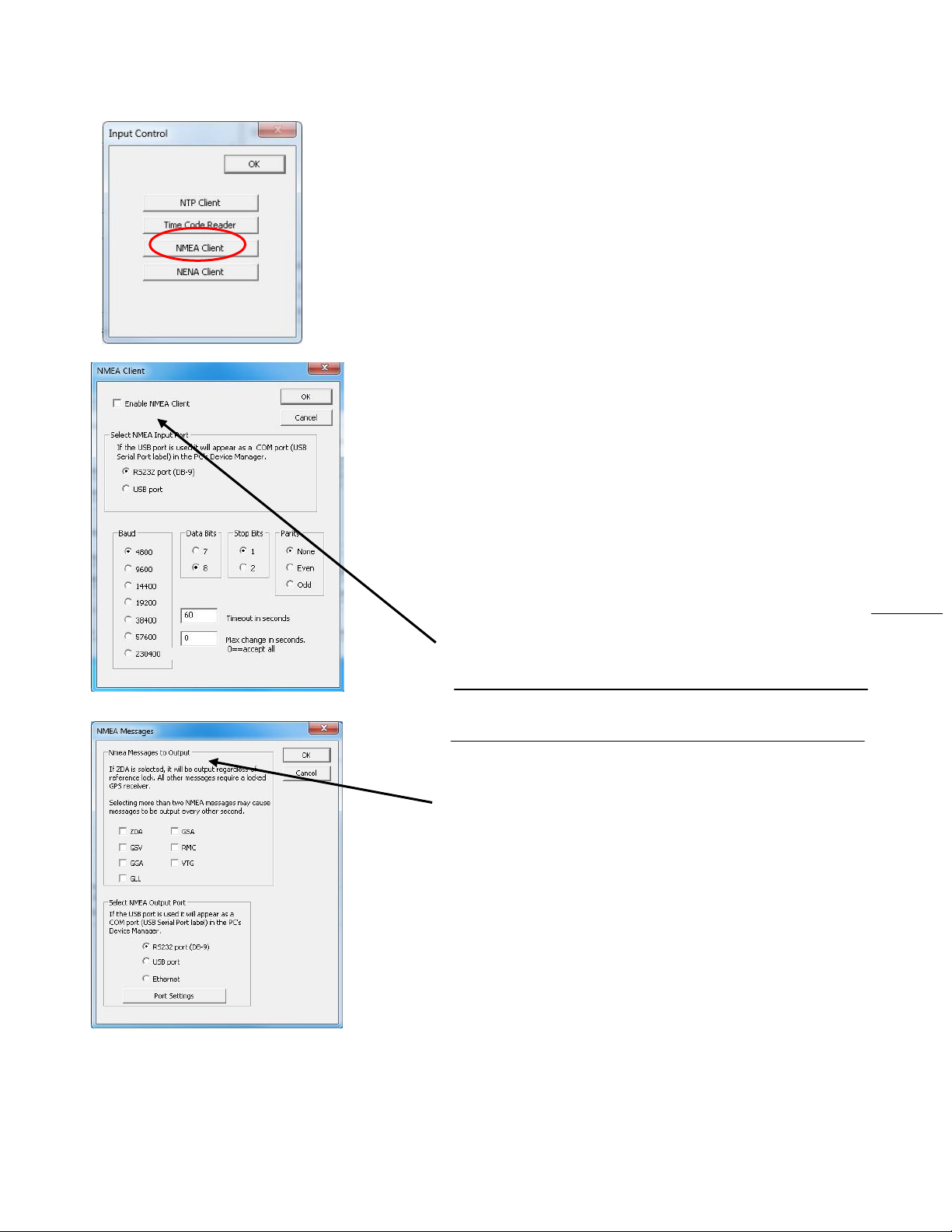
In order to activate and configure your MCR1000 for the
NMEA option, please do the following:
1. Open WinDiscovery and click the [Discover] button. If the
MCR menu does not appear, click [Discover] again.
2. Click on the MCR list [+] button
3. Click on the MCR1000 Device list [+] button
4. Click on your MCR 1000 to reveal the “Device Settings”
5. Click on [Input Control] to reveal that window
6. Click on [NMEA Client] to reveal that window
7. Click on [Enable NMEA Client]. The other options should
be preselected. Click [OK].
8. Close these windows, but keep open the Device Settings
9. Click on the [Output Control] button
10. Click on [NMEA] to reveal the “NMEA Messages” window
with the NMEA Messages to Output box. Here you may
select which one of the seven GPS sentences (ZDA/GSA/
GSV/RMC/GGA/VTG/GLL) is appropriate for your needs
11. Select a new “NMEA Output Port” if necessary
12. When done click the [OK] button.
13. Click [OK] on the NMEA Client window. Then click the
[Save and Close] button on the Device Settings window.
Masterclock MCR1000 User Manual – v.2013.08.01
Page 25
25
Output NENA with GPS
The ability to access the NENA (National Emergency Number Association, otherwise known as the 911 system)
signal is standard to the MCR1000, but requires the GPS option to operate to NENA requirements. To configure the
NENA input see the instructions on page 24, which are identical to the NEMA input. To configure the NENA output
settings, follow these instructions:
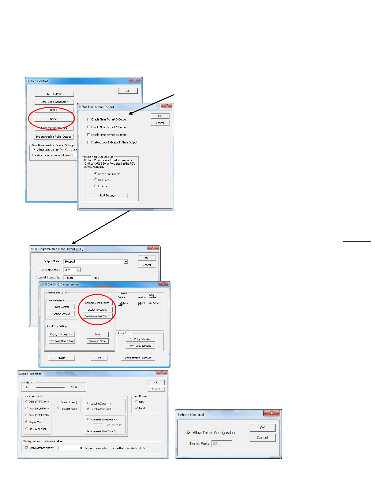
Open the Display Settings (DS) and the Output Control (OC).
Click on the [NENA] button – to provide access to the “NENA
Time Stamp Output” window. Select your preferred
format from the four choices. Select and modify the
output port.
DS > OC > TRUETIME/KINEMATICS – This button enables
selection of this output and adjustment of the port
settings.
DS > OC > PROGRAMMABLE PULSE OUTPUT – This button
operates only in the presence of a PPO device. When a
PPO device is present the window at left appears enabling
choices to be made in the Output Mode, Input Output
State, the first interval and the second interval.
DS > OC > TIME DISSEMINATION DURING OUTAGE – This
button is enabled and set by default. Customize this
setting only if required to do so.
DS > NETWORK CONFIGURATION
As on the earlier described window (p. 20), the Network
Configuration window may be viewed in summary by clicking
the [Network Configuration] selection.
DS > DISPLAY PROPERTIES
Here (below left) you can change the brightness of the display
or modify the presentation of the date and time. You can
change the display from UTC to local time and you can
alternate times with dates and set the rate at which they
change.
DS > COMMUNICATIONS CONTROL
Certain advanced features may be configured using the
[Communications Control] button. This gives access to the
Telnet Control window (below), which you may allow and set
a new port for, or retain the default port: 23.
Masterclock MCR1000 User Manual – v.2013.08.01
Page 26
26
DS > DAYLIGHT SAVINGS TIME SETTINGS
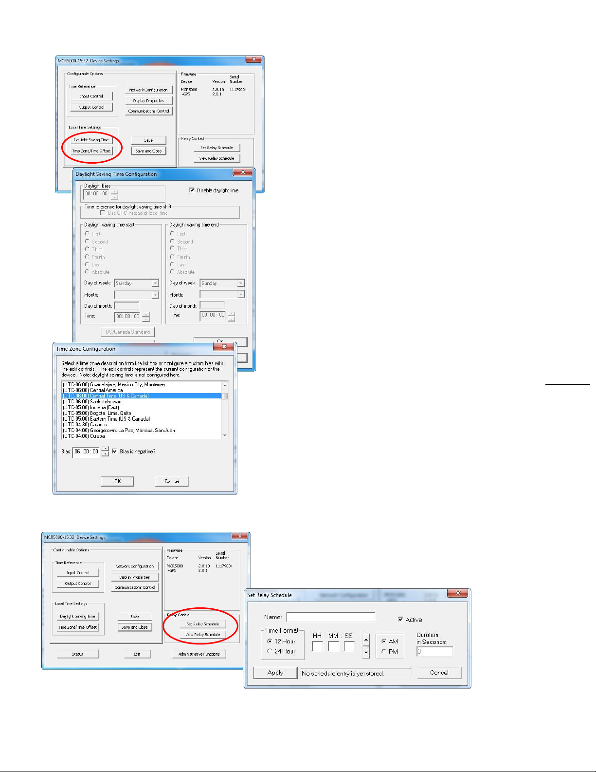
Click [Daylight Saving Time] to open this window. The clock
has complete flexibility to display any Time Zone and DST
combination.
For setting the DST rules, use one of the following options.
1. Manually enter the Daylight Saving Time rules; or
2. Click the [US/Canada Standard] button; or
3. Click the [EU Standard] (European Union) button.
4. Then Click [Current Windows Setting] to apply the
current configuration for your Windows OS.
5. Click [OK] to close the Window.
The DST rules will be saved when you click either the [Apply]
button or the [Apply and Close] button on the “Device
Settings” window.
DS > TIME ZONE/TIME OFFSET
Click the [Time Zone/Time Offset ] button to open the “Time
Zone Configuration” window. Here you’ll find a list of Time
Zones, including city and area descriptions to help with the
selection. Select the offset that fits your location and click
[OK] to close the window. Click the [Apply] or the [Apply and
Close] buttons on the “Device Settings” window.
DS > RELAY CONTROL:
SET RELAY SCHEDULE
VIEW RELAY SCHEDULE
Set a schedule of relay switch events with the [Set Relay
Schedule] button. Once a schedule has been applied to the
MCR1000, the current relay schedule information can be
retrieved to validate the entry was made correctly and the
schedule is active by using the [View Relay Schedule] button.
Click the [Apply] or the [Apply and Close] buttons on the
“Device Settings” window.
Masterclock MCR1000 User Manual – v.2013.08.01
Page 27
27
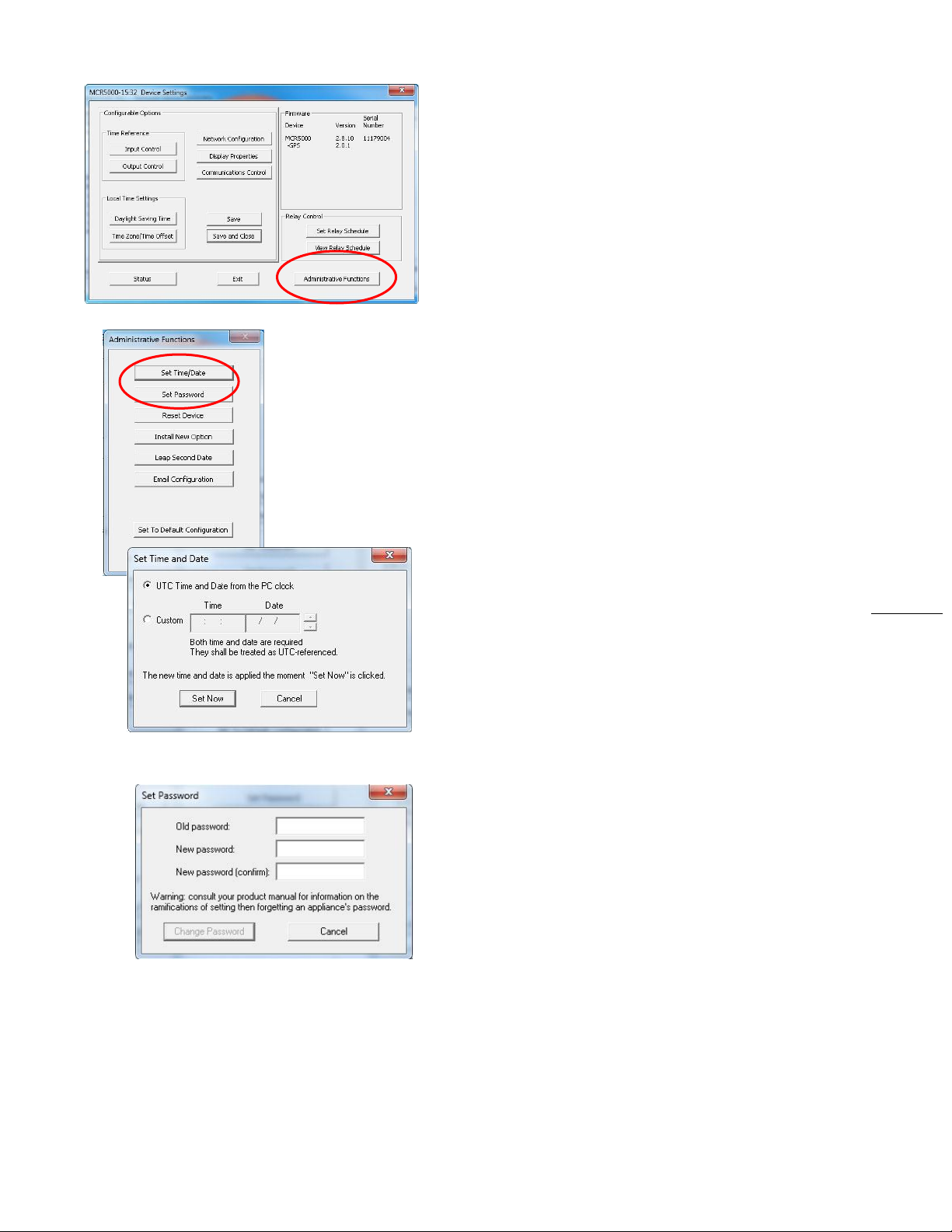
DS > ADMINISTRATIVE FUNCTIONS (AF)
Click the [Administrative Functions] button to open a menu
that is rarely accessed. These include: 1. [Set Time/Date] (for
custom time, not UTC or local time); 2) [Set Password]; 3)
[Reset Device]; 4) [Install New Option]; 5) [Leap Second
Date] (input this whenever announced); 6) [Email
Configuration] (to automatically alert you via email of any
situations within the system when they happen). Below we’ll
look at these windows in detail.
DS > AF > SET TIME/DATE WINDOW
There may be situations where you do not want to display
UTC or local time. This feature may be most useful for
demonstrations, in lab situations or in environments where
an external reference time signal is not available. Use this
when the built-in NTP client is disabled or when a network
connection to an NTP server is not available.
Click the [Set Time/Date] button to reset the time to your
preference. You will be prompted with some additional
instructions then offered the choice to continue. Click [Yes].
In the “Set Time and Date” window (left) click the [Custom]
button to enter your new time and date. Click the [Set Now]
button to activate your custom time. To return to UTC time
choose [UTC Time and Date button from the PC clock] then
click [Set Now].
DS > AF > SET PASSWORD
Click the [Set Password] button to create a new password.
You will need to enter the old password. A warning is printed
on this window concerning the ramifications of forgetting an
appliance password. In a worst-case scenario you would have
to reset the MCR1000 to its factory default settings. That
reverts back to the factory default password: “public”.
There is a second way to set a password on page 30 and
describes more fully the rules surrounding password usage.
Masterclock MCR1000 User Manual – v.2013.08.01
Page 28
28
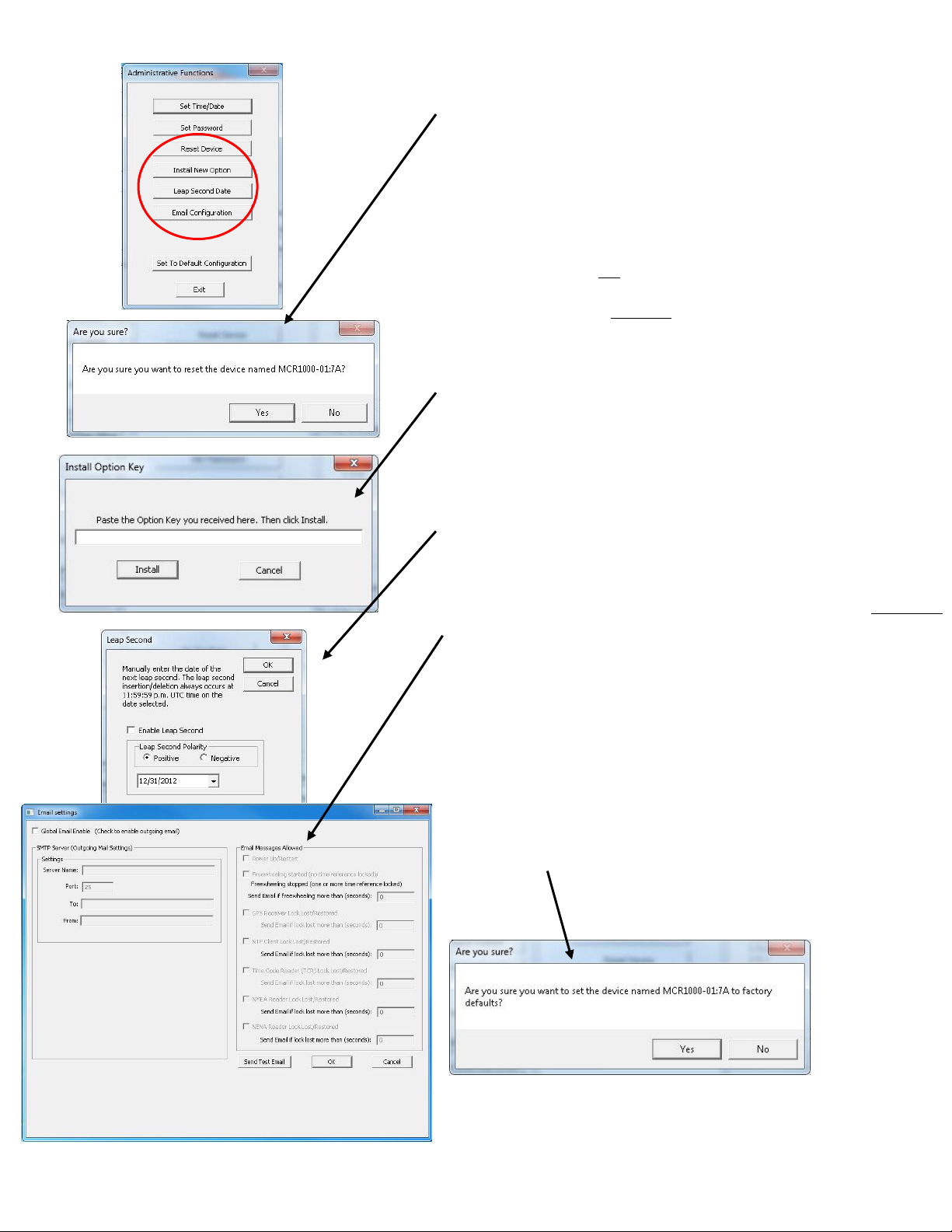
DS > AF > RESET DEVICE
Click [Rest Device] to induce a soft reset. This procedure
allows the MCR1000 to clear its current communications
buffer and re-initialize its processing, which includes another
software request for a DHCP address. This feature is intended
to allow the user to remotely reset the unit and does not
restore the factory default state.
Alternatively, if you are not in the “Administrative Functions”
window, but are viewing the list of devices after pressing the
[Discover] button, simply right click on the device you are
interested in and select the [Reset Device] button.
DS > AF > INSTALL NEW OPTION
Click the [Install New Option] button to install any new
option key you requested and received here. This will install
the new option into the software.
DS > AF > LEAP SECOND DATE
Click the [Leap Second Date] button to enable a future leap
second to occur on any specific date that you manually enter.
DS > AF > EMAIL CONFIGURATION
Click the [Email Configuration] button to generate email
alerts when certain conditions are met.
DS > AF > SET TO DEFAULT CONFIGURATION
Click the [Set to Default Configuration] button to reset all of
your previously entered options and customs settings back to
the original factory settings. You will get the “Are you sure?”
window. Click the [Yes] button if you are sure you want to
return to the default configuration with the default password:
“public”.
Masterclock MCR1000 User Manual – v.2013.08.01
Page 29
29
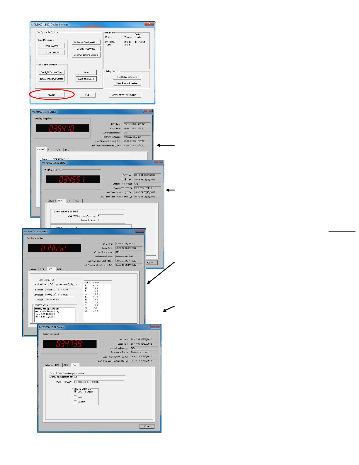
DS > STATUS
At the bottom left of the “MCR1000 Device Settings” window
is the [Status] button. The “MCR1000 Status” window
includes a “Display Snapshot” of a graphic digital clock
representing the face of the actual MCR1000 in real time. On
the right appear the “UTC Time” and date, “Local Time” and
date, the “Current “Reference” signal (in this case GPS), the
“Reference Status” (in this case Locked) and two windows
listing Last Time Lock Lost and Restored.
Below these listings are tabbed windows for Network, NTP,
GPS and TCG.
Network Tab - includes the name of the device, the model of
the device and a summary of the network configuration,
much of this data is repeated from the network
configuration window described earlier (page 20).
NTP Tab - includes a checkbox for an enabled NTP server,
plus the number of NTP requests service and the server
stratum. Also includes a checkbox for an enabled NTP
client including indications for the active server, the NTP
status, the last NTP time stamp, the largest time
adjustment, and the average time adjustment.
GPS Tab - includes time and date for Lock Lost (UTC), Lock
Restored (UTC), your geographical position, receiver
details and a list of the satellites the GPS antenna is
listening to (in this case nine) and their individual SNR
(signal-to-noise ratio, with 41.0 as the highest quality).
TCG Tab – includes the Type of Code Being Generated (in this
case SMPTE@30fps), the Raw Time Code and the Time
to Generate whether you choose UTC, Local or Custom.
Masterclock MCR1000 User Manual – v.2013.08.01
Page 30
30
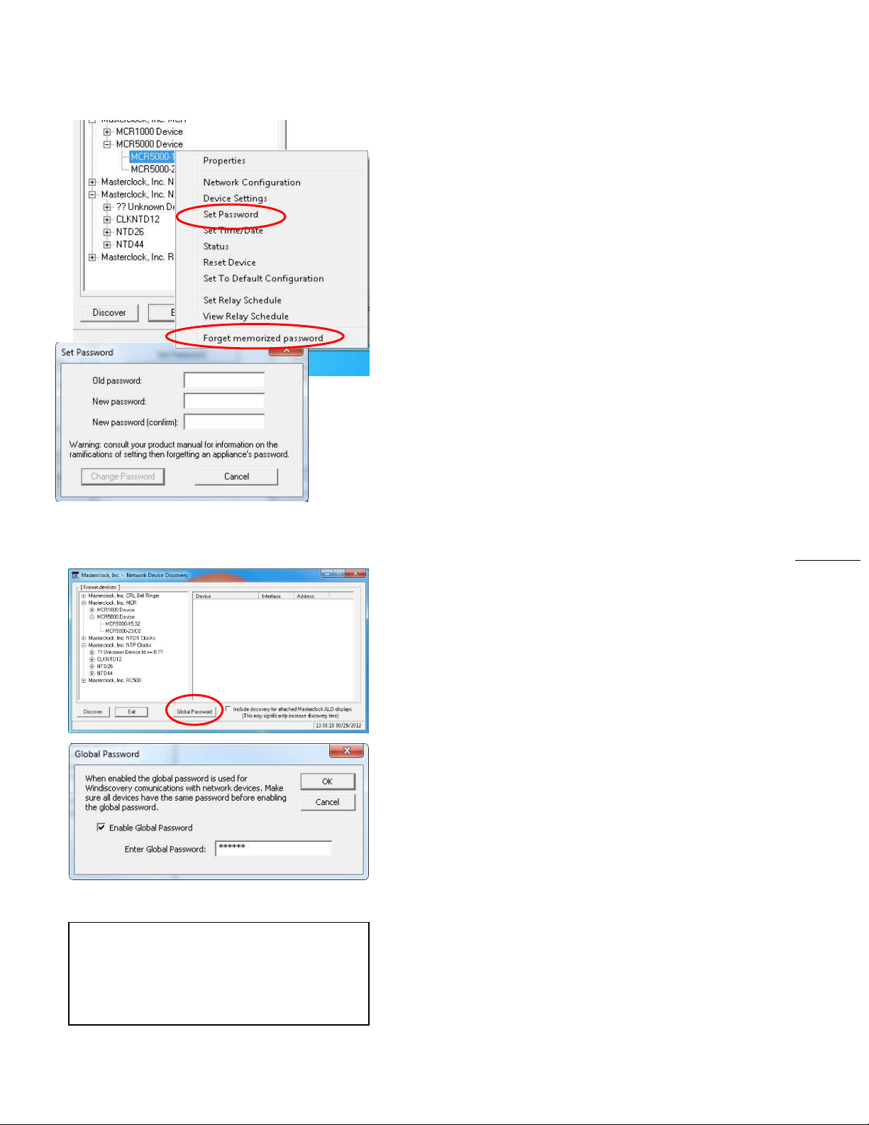
The Global Password being used must match
the password on all the devices being
administered. On any new system being
installed, the factory default global password is
“public”.
Right click the device to bring up this menu
SET PASSWORD
Each Masterclock device in your network may have its own
password (see the “Properties” window to [Set Password]),
or you may create a Global Password on the “Discover”
window (see below). The default password is “public”.
Your custom password should be one to eleven characters
and is case-sensitive. For added password strength, you
should use both alphanumeric and special ASCII characters.
The password must be entered twice to confirm the entry.
Click [Change Password] to save it.
When a password is set for a device, each time you click [OK],
[Apply] or [Apply and Close] for that device you will be asked
for the password. You can select the [Remember this
password for the session] button and you will not be
prompted for the password, until you restart WinDiscovery.
Or you can use the Global Password feature (see below).
If you enter the wrong password and selected the
[Remember this password for the session] checkbox, you will
receive an error upon clicking [OK], [Apply] or [Apply and
Close] to any configuration changes. You can close the
WinDiscovery session to forget the wrong password(s).
However, this will require entering the password(s) again for
each device.
You can also remove the incorrect password entry during a
WinDiscovery session by going to the drop-down menu for
the device (right click to see this) and selecting the [Forget
memorized password] button.
GLOBAL PASSWORD
The Global Password feature allows the user to enter a single
password once for all NTP devices. During subsequent
sessions you will not have to reenter the password.
ENABLING / DISABLING GLOBAL PASSWORD
To enable the Global Password:
1. Check “Enable Global Password”
2. Type your password.
3. Click [OK]
To disable the Global Password:
1. De-select the “Enable Global Password” checkbox
2. Click [OK].
Masterclock MCR1000 User Manual – v.2013.08.01
Page 31
31
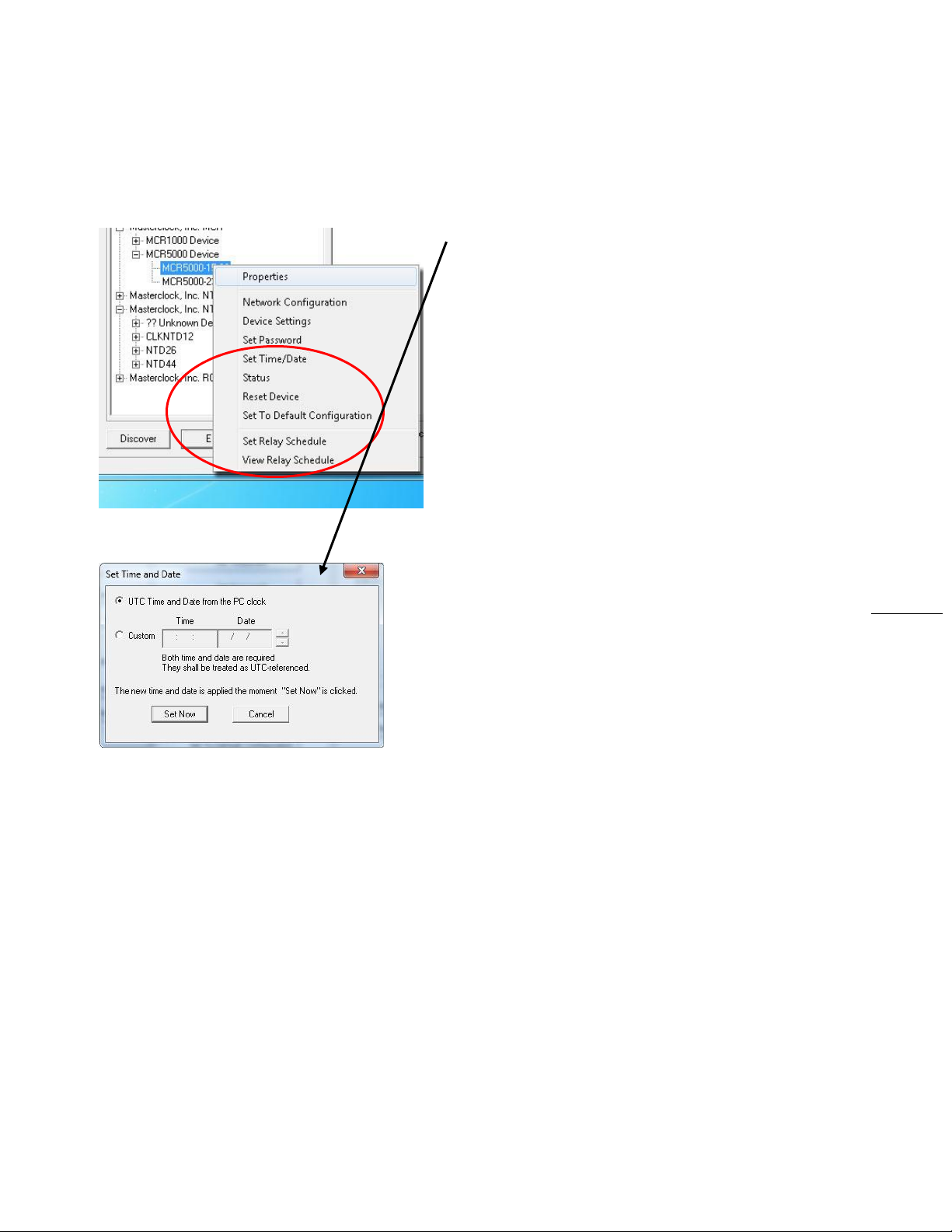
FROM THE RIGHT CLICK PROPERTIES MENU
THE FINAL SIX CONFIGURATIONS:
SET TIME/DATE
Click the [Set Time/Date] button and a window appears
reminding the user, “This feature is only to be used to set the
UTC time and date if the device is not locked to a reference
and is free-wheeling. “ Other cautionary remarks follow. At
the bottom of the window you may choose to continue or
not. If you choose the [Yes] button, the “Set Time/Date”
window appears, previously seen on page 27.
STATUS
See “Status” window, page 29.
RESET DEVICE
See ”Reset Device” window, page 28.
SET TO DEFAULT CONFIGURATION
See ”Set to Default Configuration” window, page 28.
SET RELAY SCHEDULE
See ”Set Relay Schedule” window, page 26.
VIEW RELAY SCHEDULE
See ”View Relay Schedule” window, page 26.
.
Masterclock MCR1000 User Manual – v.2013.08.01
Page 32
32
Note: The ANYCAST mode is not used.
How to Listen for NTP
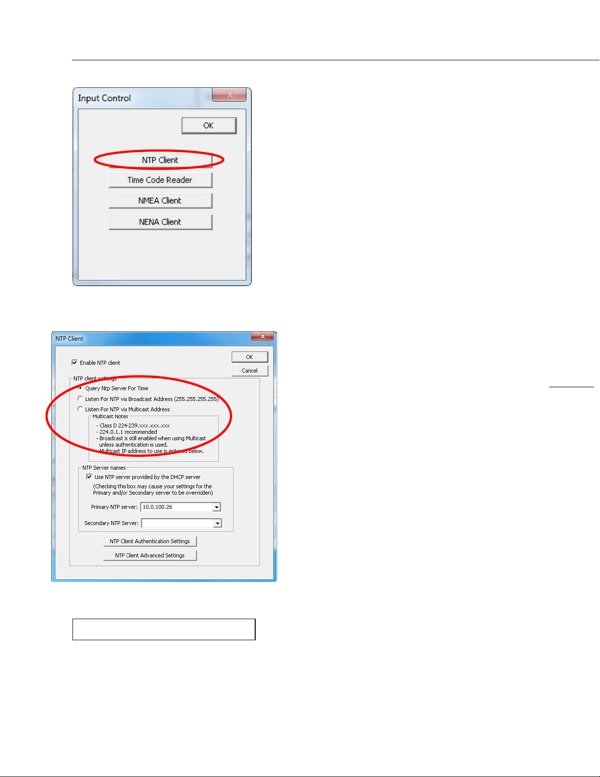
DS > IC > NTP CLIENT
To access the NTP addressing modes in the “NTP Client”
window, click on the [NTP Client] button on the “Input
Control” window (at left).
NTP CLIENT SETTNGS BOX
QUERY NTP SERVER FOR TIME (UNICAST) – The MCR1000
supports this method of NTP packets transfer by default.
There is a query and direct transfer of information from
the NTP server to the NTP client. Whenever the
broadcast or multicast modes are selected the unicast
method is also supported simultaneously.
BROADCAST – The network clock can be configured to listen
to NTP broadcasts by selecting the [Listen for NTP via
broadcast address 255.255.255.255] radio button.
The broadcast timeout is adjustable under the [NTP
Client Advanced Settings] button at the bottom of this
window. The default timeout is 3600 seconds (one hour).
The default broadcast configuration is to query the NTP
server at 10-minute intervals. In this mode the clock drift
is ±1 minute per year, with adjustments as needed.
MULTICAST – The network clock can be set up to listen to
NTP using multicast addressing by selecting the [Listen
for NTP via multicast address] radio button.
When enabled, the Multicast Class D/Group Address
(Class D 224-239.xxx.xxx.xxx) may be specified as well as
the frequency that multicast broadcasts will be issued.
This can be changed as desired in the “Primary NTP
server” and “Secondary NTP Server” menu boxes in this
window. These groups (or Class D address ranges for
multicasting) are defined and governed by RFC3171,
IANA IPv4 Multicast Guidelines.
Typically, the multicast address range from 224.0.1.0 to
224.0.1.255 (aka: Internetwork Control Block) is used for
NTP traffic. However, please refer to the RFC link below
for your specific application and implementation.
http://www.elook.org/computing/rfc/rfc3171.html
Masterclock MCR1000 User Manual – v.2013.08.01
Page 33
33
The static IP address you enter must not be in use
by another device on the network. This includes IP
address ranges reserved for use by the DHCP server.
If a static IP address creates a duplicate IP address
condition, the network clock will be assigned a
fallback IP address of “169.254.xxx.xxx.”
The “169.254.xxx.xxx” address is a link local address
range (not allowed on the Internet) that is used by
Microsoft whenever their DHCP clients cannot find a
DHCP server.
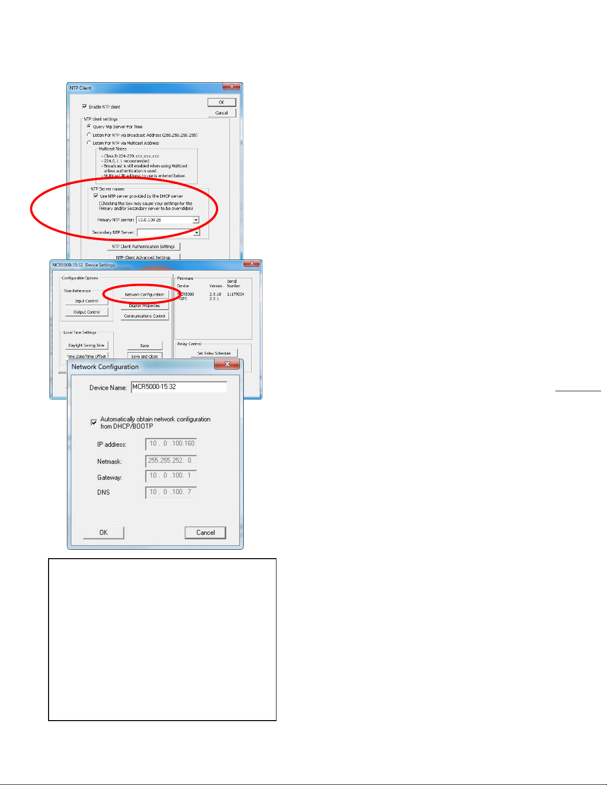
NTP SERVER NAMES BOX
The default factory setting for network configuration is to
[Use NTP server provided by the DHCP server] checkbox.
Fallback Address – If a DHCP server cannot be found on the
network by the NTP clock, the IP address will be assigned a
fallback IP address of 169.254.xxx.xxx.
If you choose to deselect the default server, you must
provide a static IP Address, here called the “Primary NTP
Server:” Then provide a “Secondary NTP Server”.
Similarly, back under the “Device Settings Window,” click the
[Network Configuration] button and de-select the
[Automatically obtain network configuration from
DHCP/BOOTP] checkbox. Then provide the IP address,
Netmask, Gateway, Primary DNS appropriately.
Devices that cannot find the primary server and have been
assigned a fallback IP address of 169.254.xxx.xxx will be
displayed in the main WinDiscovery window with RED text,
indicating a problem.
NTP CLIENT AUTHENTICATION SETTINGS
The NTDS series uses the MD5 Message Digest Algorithm,
which is a widely used cryptographic hash function that
produces a 128-bit hash value.
http://en.wikipedia.org/wiki/MD5
NTP CLIENT ADVANCED SETTINGS
From the NTP Client window, the [NTP Client Advanced
Settings] button allows for the adjustment of additional
network communication settings. Under most operating
circumstances it is not necessary to change these settings.
The factory-default TCP/UDP port for NTP service is: “123”
Masterclock MCR1000 User Manual – v.2013.08.01
Page 34
34
Port 23
Some NTP/SNTP servers will expect NTP
clients to operate on port 123.
If the advanced settings have been altered
for your clock and you begin experiencing
difficulty in getting your clock to synchronize
to the NTP time server, or the clock begins
acting erratically, try returning the advanced
settings to the default values: “23.”
Using Telnet
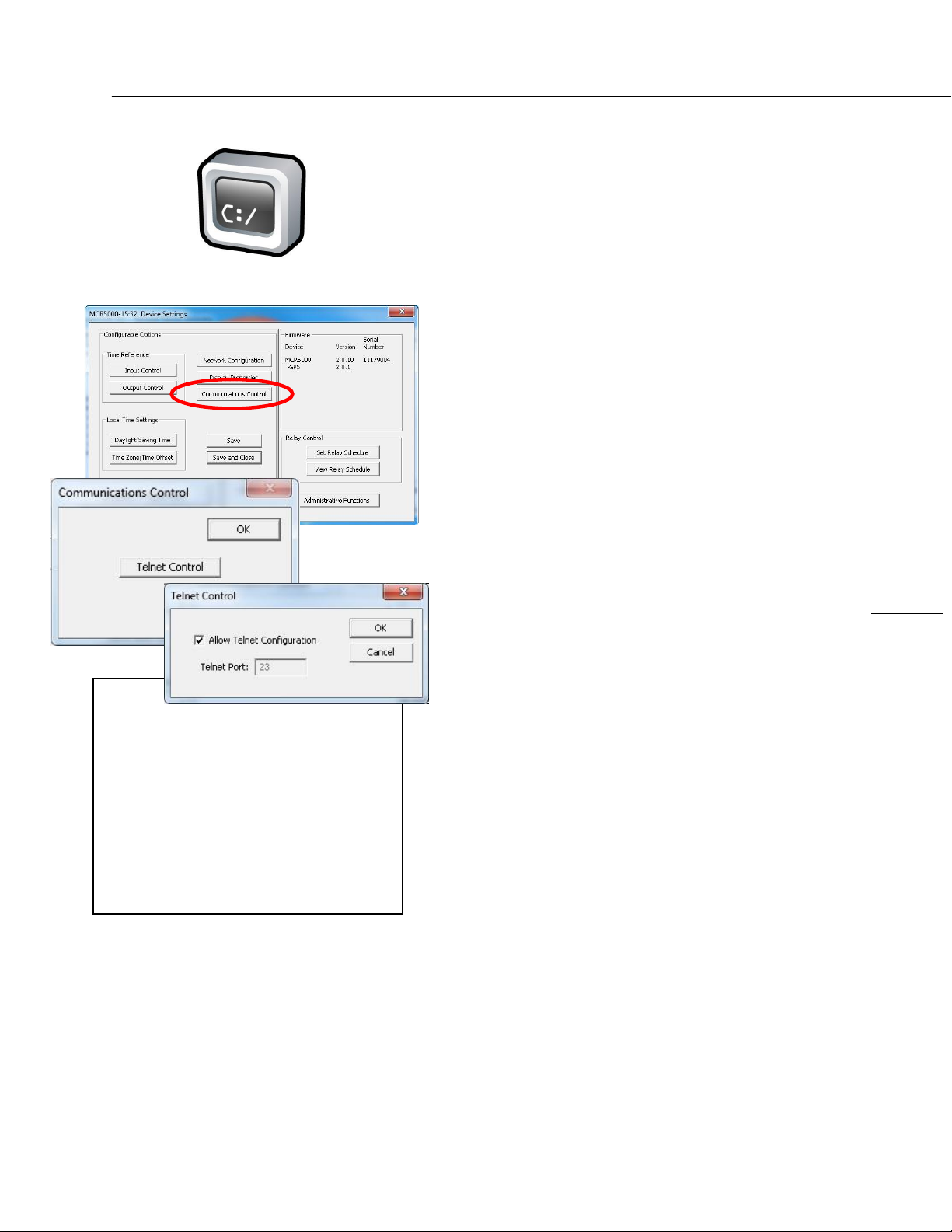
TELNET OPTION
Typically in Windows OS you’ll use the free WinDiscovery app
to establish first-time networking configuration. However, in
other operating systems you may use Telnet to configure
your DHCP server.
To access the Telnet button, go back to “Device Settings” and
click the [Communications Control] button. In the
“Communications Control” window, click the [Telnet
Control] button and select [OK]. By default the Telnet Port is
set at 23. If you wish to change it, deselect the [Allow Telnet
Configuration] checkbox and click [OK].
PORT DEFINITION – If Telnet is allowed, the port must be
defined. The default Telnet port is 23. See your network
administrator if you need additional information.
IP ADDRESS – If Telnet is allowed, the IP address of the unit is
required. By default, the MCR1000 is configured to obtain an
IP address via DHCP. Configuration via Telnet may not be
convenient for devices operating with a factory default
network configuration since the IP address is not known.
Telnet username: public. Telnet password: public.
Masterclock MCR1000 User Manual – v.2013.08.01
Page 35
35
Time Code Generator Option
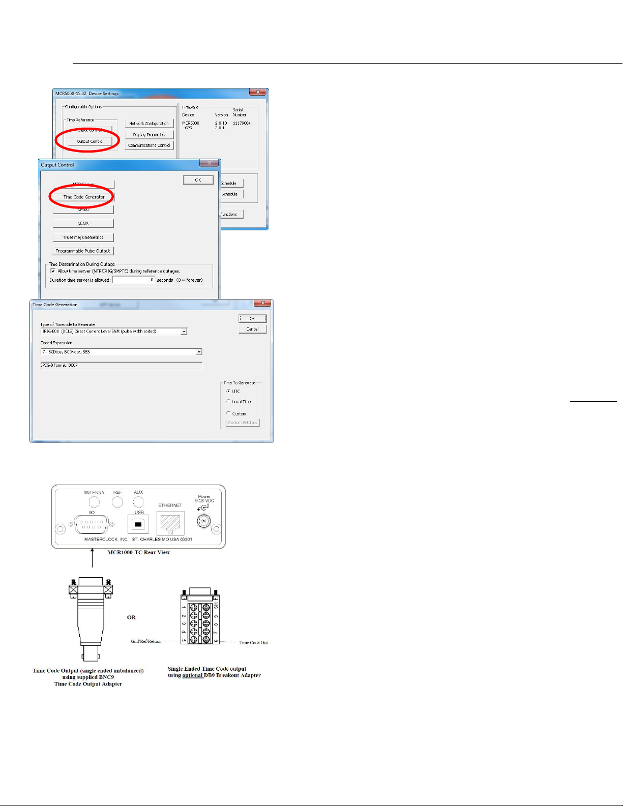
If you have the Time Code Generator Option (page 9) you will
need to open the “Device Settings” window for your
MCR1000, then click the [Output Control] button, then click
the [Time Code Generator] button.
The “Time Code Generation” window allows you to choose
the “Type of Time Code to Generate” and the “Coded
Expression”. Modify these options to fit your location.
Then, within the “Time To Generate” box, select Local Time
or Custom Time if different than the UTC default.
OTHER DROP DOWN MENUS
Depending on your options, other drop down menus will
appear in this Time Code Generation window.
In the “Type of Timecode to Generate” window all IRIG
choices create two further dropdown windows, as shown at
left. SMPTE choices create one drop down menu and a
checkbox.
If you do not change these selections the default selections
will remain in effect.
Click the [OK] button when all your choices have been made.
OUTPUT TIME CODE CONNECTIONS
Connect the Time Code signal cable to a DB9 breakout
adapter supplied with the unit and then to a valid UTC
referenced Time Code signal source.
Masterclock MCR1000 User Manual – v.2013.08.01
Page 36
36
GPS ANTENNA – SMA FEMALE
Masterclock highly recommends using only
the pre-made/pre-tested antenna cables
provided by Masterclock, Inc. For best
performance, it is best to order these
cables (see available antenna packages,
page 37) at the same time that you order
your MCR1000 with GPS option installed
since the unit has been factory tested as a
system with the antenna cables and
antenna before shipment.
Note: All components of the GPS system
(including the MCR1000 unit with GPS receiver,
power supply, GPS antenna and antenna cable)
are tested as a system at the factory before
shipment.
Be sure:
1) the GPS antenna, the MCR1000 and the
supplied coaxial antenna cable have not
been damaged;
2) the GPS antenna has an unobstructed view
of the sky;
3) the power connector is properly installed;
4) and the front panel LED follows the startup
sequence described earlier (on, off and
then on).
GPS Input Option
With the GPS input option the MCR1000 derives precision
UTC time from satellites. The MCR includes an internal
receiver that requires a pre-amplified GPS antenna.
GPS ANTENNA CONNECTIONS
1. Disconnect power from the unit.
2. Provide the antenna with a clear view of the sky. Do not
move it again until after the MCR1000 has achieved
satellite lock (explained below). Route the antenna cable
to the back of the MCR1000.
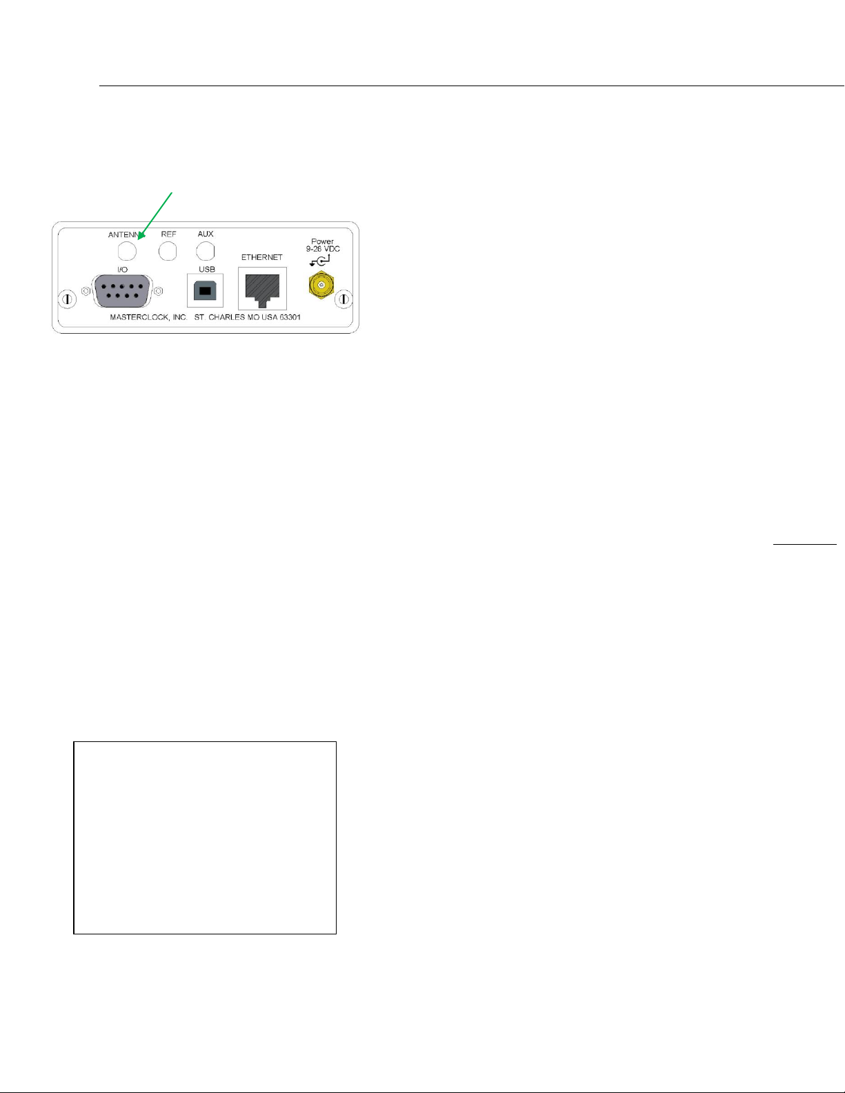
3. Connect the antenna cable coaxial connector to the gold
SMA female connector on the rear of the unit (labeled
ANT in image at left).
4. Reapply power to the MCR1000.
START-UP AND GPS SATELLITE ACQUISITION
When the MCR1000-GPS is initially powered up the time to
acquire satellites and extract correct time is typically 5 to 15
minutes. In less than optimal conditions this could extend to
25 minutes. Atmospheric conditions, type of antenna,
antenna location and antenna cable length will affect
acquisition time.
When restarting, if the location, time and number of satellites
have not significantly changed since last power down, the
MCR1000 should start up much faster.
GPS LOCK RELATED ISSUES AND
TROUBLESHOOTING TIPS
The following problems are specific to the MCR1000 with GPS
option installed. These should be considered only after the
25-minute satellite acquisition time has elapsed.
PROBLEMS:
Unit is not locking to GPS.
The LED on the front panel is always steady ON.
Unit is not serving time.
WinDiscovery displays no GPS satellite information.
Masterclock MCR1000 User Manual – v.2013.08.01
Page 37
37
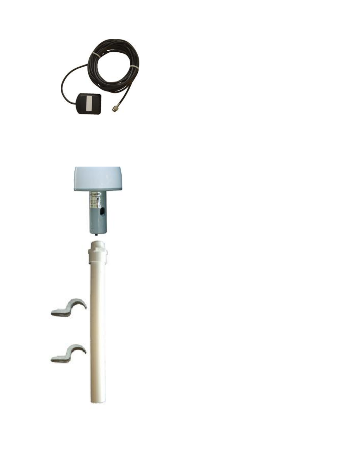
Above: Basic Antenna
Included with GPS option.
Below: Standard antenna and
PVC pole.
SYMPTOMS, REASONS AND SOLUTIONS
STEADY ON: The reference lock LED stays steady ON when
the unit has not locked to GPS and is not serving NTP time.
FLASH ONCE PER SECOND: The reference lock LED (page 5,
green, PWR) will flash once per second when locked to GPS.
FLASH TWICE PER SECOND: The reference lock LED (green,
PWR) will flash twice per second when freewheeling (running
without external signal, reference from internal oscillator).
The MCR1000 must first acquire an initial lock to GPS before
it will serve accurate time. Once locked, the unit can continue
to serve time (either while locked to GPS or while
freewheeling) as long as the DC input power is not
interrupted.
Some procedures to consider:
1. Wait at least 20 to 30 minutes if installing the GPS
receiver device in a new location. The GPS receiver must
find and acquire the signal from at least four GPS
satellites simultaneously and will continue to acquire up
to the eight satellites. When placed in a new location,
time to first lock can be quite lengthy since the receiver
must update its internal almanac and ephemeris data
from the satellite signals.
2. Make sure the GPS cables and connectors are not
damaged and the threaded connectors are tightly
coupled.
3. Relocate and reinstall the GPS antenna outdoors with a
clear/unobstructed view of the sky. Find a rooftop or
similar location such as a large open field or parking lot
with an unobstructed view. While the MCR may lock to
GPS on some occasions with the antenna located indoors
near a window, such use is not recommended. Your GPS
antenna must not be near satellite dishes or sources of
RF interference, such as transmitters or other antennas.
4. Replace your cable and connectors. Your antenna cable
or connectors may be shorted or open.
5. Check your cable length. You may be using too long of an
antenna cable or using an improper impedance cable. If
necessary, remove the long antenna cable and connect
the MCR1000 directly to the short cable on the GPS
antenna using the short SMA male to SMA male adapter
provided with your antenna package. Preferred and
tested GPS antenna cable is available from Masterclock
in lengths up to 500 feet (152m).
Masterclock MCR1000 User Manual – v.2013.08.01
Page 38

38
Note: Damage to the GPS receiver is not
covered under warranty.
If you need uninterrupted precise time,
please purchase a spare MCR1000 with a
GPS option. Order your first MCR1000 with
additional TCR or HSO as a backup
reference.
For repairs contact technical support at
Masterclock (see page 56 for contact).
Note: Damage to the GPS cables is not
covered under warranty.
If the GPS antenna or cables are damaged
please contact Masterclock to order
replacements.
GPS antenna cannot be repaired.
The MCR1000 with a GPS module installed
requires a pre-amplified antenna. The
MCR1000 provides +3 VDC via the center
pin of the SMA coaxial cable/connector for
remote power to the antenna.
WARNING: Attaching a passive (non-preamplified) antenna to the MCR1000 could
destroy the GPS receiver module. This is a
major repair cost which is not covered by
warranty.
6. Internal damage: The GPS receiver located within the
unit may have been damaged during the installation or
handling. Handle the MCR as you would any electronic
device. Do not subject the assembly (particularly the
antenna input connector) to electrostatic discharge (ESD)
during handling. When handling or installing the device,
observe proper ESD protection methods. At a minimum,
discharge yourself to a convenient ground before
handling theMCR. Preferably, use a static discharge wrist
strap connected to Earth ground when handling,
installing and/or configuring the device.
7. Inappropriate power application: The MCR-GPS option
provides power to the pre-amplified GPS antenna using
low voltage supplied on the center pin of the antenna
cable. To avoid damage to the GPS receiver (and/or
antenna) caused by a short circuit, make all antenna
connections only after all power is removed from the
unit.
8. Incompatible antenna: Do not use antennas provided by
others. They may not be compatible with the GPS
antenna supplied with your system and may damage the
MCR-GPS receiver unit.
9. Damage during installation: The GPS antenna cables can
be damaged by pulling and twisting the connectors. You
should also avoid pinching and over-bending the cables.
Such abuse may occur while using a cable puller. Ensure
that you do not pull directly on the connectors during the
installation. Ensure that you do not twist the connector
at the location where the connector meets the cable, as
this can damage the braid. The coaxial cable should not
be crushed, crimped or bent at a sharp angle nor should
it be strained by pulling.
10. Coiling If the cable is to be coiled for storage, the coil
diameter should be at least six inches for quarter-inch
cable, twice that for larger cable diameters.
If your GPS antenna cables are damaged please contact
Masterclock to order replacements.
Masterclock MCR1000 User Manual – v.2013.08.01
Page 39

39
D-Sub Connector 1
D-Sub Connector 2
Dsub1
Signal
Signal
Dsub2
2
Transmit Data
Transmit Data
2
3
Receive Data
Receive Data
3 5 Signal/System Ground
Signal/System Ground
5
D-Sub Connector 1
D-Sub Connector 2
Dsub1
Signal
Signal
Dsub2
2
Receive Data
Transmit Data
3
3
Transmit Data
Receive Data
2 5 Signal/System Ground
Signal/System Ground
5
Pin
Signal
MCR1000 signal name
2
TxD
Transmit Data
3
RxD
Receive Data
5
SG
Signal/System Ground
DB9 Breakout Adapter
(item sold separately)
NMEA and the RS-232 Interface
DS > OC > NMEA
In order to receive NMEA (National Marine Electronics
Association) 0183 sentences (messages), the RS-232 interface
[DB-9 male connector] may be used to connect your PC with
your MCR1000.
Unless the GPS option is included, only ZDA sentences will be
output as they contain only UTC time and date signals. Other
sentences with latitude and longitude data are available with
the GPS option (page 40).
SERIAL PINOUT FOR RS-232
The MCR1000 serial port pinout is
defined at left. RS-232 communications
from a standard IBM PC or compatible
host computer use a standard straight
thru cable (3 wires only: pins 2, 3 and 5).
The default communication settings for
the RS-232 port are: 4800 baud, 8 data
bits, 1 stop bit, no parity.
The RS-232 port can be configured for baud rates of 4800,
9600, 19200, 38400, and 57600; along with 7 or 8 data bits, 1
or 2 stop bit. The parity bits can be selected as None, Odd,
and Even.
FOR OTHER TYPES OF
RS-232 RECEIVERS
it may be necessary to observe the
following requirements:
• Connect the Transmit (TX) line of the
MCR (pin 3 of the DB-9 connector) to the
Receive (RX) line of the host system.
• Connect the Receive (RX) line of the clock (pin 2 of the DB-
9 connector) to the Transmit (TX) line of the host system.
• Connect the Ground Line of the clock (pin 5 of the DB-9
connector) to the ground of the host system.
• Ensure the host system can communicate via standard
RS-232 at 4800 baud, 8 data bits, I stop bit, no parity.
• Pins 2 and 3 must use RS-232 voltage levels. The MCR1000
cannot decode TTL-level serial communications at pin 2
and 3 of the DB-9 connector.
Masterclock MCR1000 User Manual – v.2013.08.01
Page 40
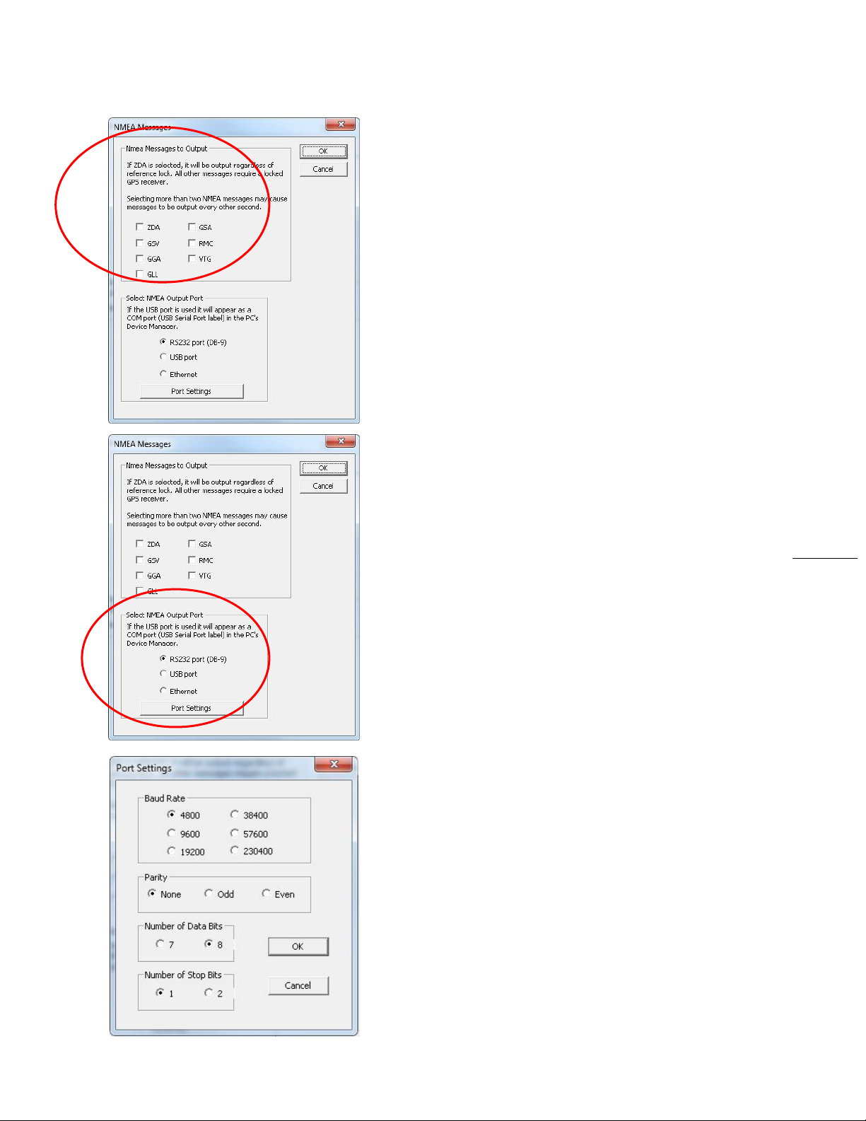
40
• Ensure that any cable you are using for communication
with the MCR1000 is within the RS-232 standard length
and is a working cable.
• The interface may require a null modem cable.
• A “null modem” 3-wire serial cable or simple RS-232 cable
utilizing pins 2,3 and 5 only should be used
ADDITIONAL NMEA MESSAGES TO OUTPUT
WITH THE GPS OPTION
The MCR1000 can output additional NMEA 0183 sentences
(aka: messages). If you have the GPS option these can be
accessed by simply checking the appropriate boxes (at left)
on the “NMEA Message” page.
ZDA - GSV GGA GLL GSA RMC VTG
Note: Selecting more than two NMEA sentences may cause
the sentences to be output every other second as opposed to
every second. This characteristic is an inherent function of
the GPS receiver and is particularly true when selecting GSV
sentence output.
When GSV is selected, up to three GSV sentences will be
output with information coming in from at least four
satellites per sentence. It would help to manually increase the
baud rate (maximum = 57600) when adding additional
sentences to help increase delivery capability.
SELECT NMEA OUTPUT PORT
The first two selections (RS-232 and USB) produce a “Port
Settings” window (lower left) with preselected [Baud rate],
[Parity], [Number of Data Bits] and [Number of Stop Bits]
buttons.
RS232 PORT SETTINGS
On the “NMEA Messages” window select the [RS232
settings] button. Click on the [Port Settings] button to adjust
the baud rate and communications settings. Select from baud
rates of 4800, 9600, 19200, 38400, 57600 and 230400.
The parity bits can be selected as None, Odd, and Even.
The number of Data Bits can be set to 7 or 8.
The number of Stop Bits can be set to 1 or 2.
The default settings are 4800 baud, 8 data bits, no parity,
8 data bits and 1-stop bit.
THE USB BUTTON REVEALS SIMILAR SETTINGS.
Masterclock MCR1000 User Manual – v.2013.08.01
Page 41
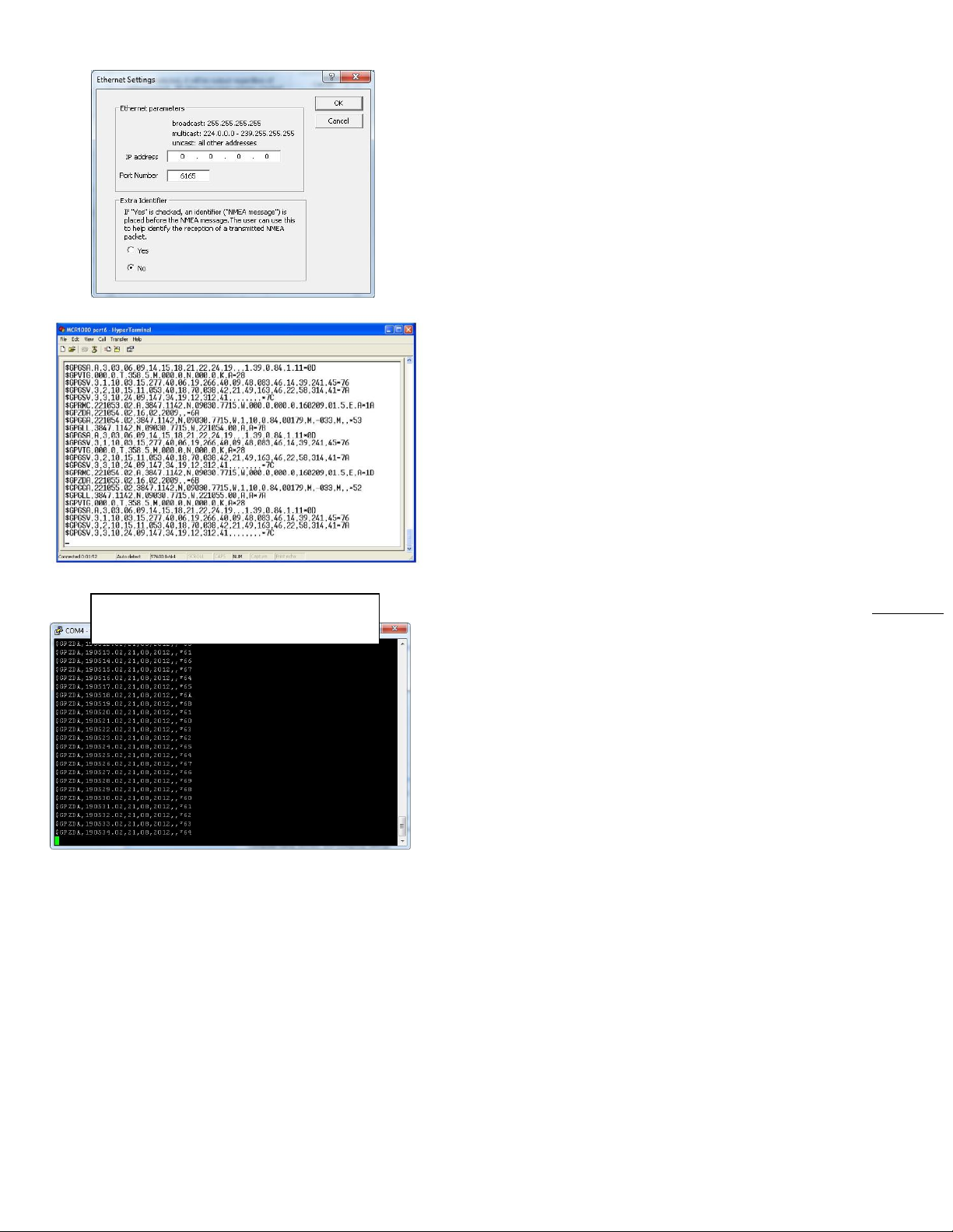
41
Above: NMEA data on HyperTermincal
Below: NMEA data on PuTTY
ETHERNET SETTINGS
The third selection from the “NMEA Output Port” box
produces the window at left, “Ethernet Settings.” Here you
may adjust the “IP Address” and “Port Number.”
You may also select to output an “Extra Identifier” to
precede every NMEA message by clicking the [Yes] button.
STREAMING NMEA DATA USING HYPERTERMINAL
Incoming NMEA sentences may be monitored on a legacy PC
OS using HyperTerminal (at left) which was bundled with
earlier versions of Windows. HyperTerminal Private Edition
and HyperACCESS are paid upgrades that continue to support
more recent versions of Windows. The HyperTerminal image
at left was provided by a legacy system. It portrays several
seconds of satellite data.
STREAMING GPS DATA USING PUTTY
For those of you with a more recent PC OS you may access
several sentences of GPS data by using PuTTY.exe (at left).
1. Assuming all electronic connections have been made...
2. Open WinDiscovery.
3. Click on the [Discover] button.
4. Right click on your MCR1000 to reveal the MCR1000
“Device Settings” window.
5. Click on the [Output Control] button.
6. Click on the [NMEA] button.
7. That reveals the “NMEA Messages” window. In the
upper box, select ZDA or any other NMEA sentence.
8. In the lower box (NMEA output port), select the [USB
port] button and click on [Port Settings].
9. Select your BAUD rate (e.g. 9600). Parity = None.
Number of Data Bits = 8. Number of Stop Bits = 1.
Click [OK].
10. In the “NMEA Message” window, click [OK].
11. When the “Output Control” window reappears,
click [OK].
12. When the MCR1000 “Device Settings” window
reappears. Click [Save and Close].
13. When the “WinDiscovery” window reappears.
click [Exit].
Masterclock MCR1000 User Manual – v.2013.08.01
Page 42

42
14. Open PuTTY.exe.
15. Click the [Run] button.
That reveals the “PuTTY Configuration” window. On the right
input your basic options for your PuTTY session:
16. For “Connection Type,” select the [Serial] button.
17. That reveals “Serial Line” and “Speed” choices that are
automatically filled in. If they need to be changed to
match the settings you earlier input to WinDiscovery
(step 9), then do so.
18. Click the [OPEN] button.
19. This reveals another PuTTY window displaying streaming
satellite data (at left) incrementally delivered onscreen
once per second. ZDA data delivers UTC time and date.
Other sentences deliver geographical coordinates.
NTP Client Information
If you want to synchronize PCs, workstations and servers to
your MCR1000 you must incorporate a NTP/SNTP client. This
client is responsible for asking the NTP server for time/date
information. In some cases it simply listens on the network
for NTP time broadcasts, then sets the internal time of the
computer or device. NTP client applications come in a variety
of offerings, supporting different features, with different
levels of accuracy, fault tolerance and reporting. Many are
inexpensive to license, or are free (like this client app from
Masterclock).
FREE SNTP CLIENT SOFTWARE
Masterclock provides a FREE Simple Network Time Protocol
(SNTP) client for use to synchronize PCs, workstations and
servers. This client app is called MasterSyncPC Freeware and
it can be downloaded at the Masterclock website.
https://www.masterclock.com/MasterSyncPC2.php
The software is provided as-is, as a courtesy to our
customers, with no technical support provided. This
application is developed to run under Windows 2000,
Windows XP, 7, Server 2003 and 2008 SP-1.
Masterclock MCR1000 User Manual – v.2013.08.01
Page 43
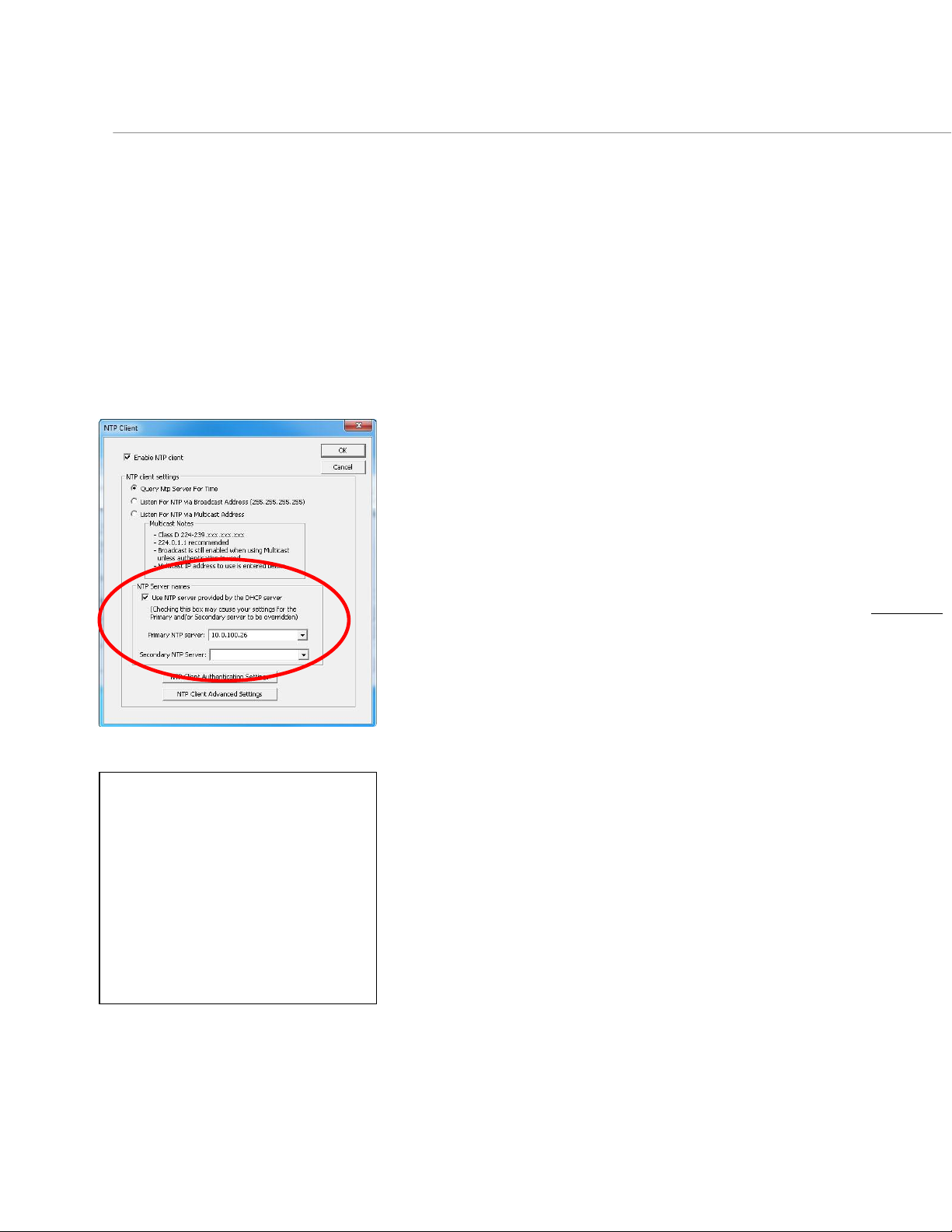
43
Synch Problems?
If the advanced settings have been
altered for your device and you begin
experiencing difficulty in getting your
clock to synchronize to the NTP time
server, try returning the advanced
settings to the default values shown
above.
Also do this if the clock begins acting
erratically, performing soft restarts, etc.
“Soft” Restarts
A ‘soft’ restart may be performed periodically by the
MCR1000 to automatically rectify problems it senses:
1. If the MCR is not receiving NTP poll responses;
2. If the MCR is not receiving broadcast responses;
3. Or if the MCR is set to use DHCP and cannot find it.
You will recognize a soft restart when the MCR1000 green
PWR LED begins to blink twice per second for a short time.
You may even hear a quiet relay click.
THE TIMEOUT PRIOR TO A SOFT RESTART
IS TEN MINUTES OR MORE
Several factors can increase the time between soft restarts.
1. All soft restarts will be delayed by two hours if a
connection is made by Telnet or WinDiscovery.
2. A soft restart could be delayed if the user changes the
default parameters for NTP poll retries/timeouts or the
NTP broadcast times out. For example, if the NTP
broadcast timeout is increased to 60 minutes, the soft
restart timeout will also be increased to 60 minutes.
The primary and secondary server information (at left) can be
automatically configured by the DHCP server when selecting
the [Use NTP server(s) address provided by DHCP server]
checkmark, provided your DHCP server is configured to do so.
Consult an IT/network administrator to utilize this option
[DHCP Server Option 042].
The default port for NTP service is 123. This can be changed if
desired. [Note: Some NTP/SNTP servers will expect NTP
clients to operate on port 123 and cannot be configured to
utilize alternate ports.]
Some NTD clocks will only operate in Unicast/Query mode
using server port 123. This mode is selected exclusively when
neither the “Listen for NTP Broadcast” nor the “Listen for
NTP Multicast” modes are selected.
Masterclock MCR1000 User Manual – v.2013.08.01
Page 44

44
Software Tip:
WinDiscovery uses bi-directional UDP
messaging on port 6163 for both the
discovery process and to communicate
configuration. It also sends status packets to
and from all Masterclock network devices on
this port.
Delivery of UDP messages (packets) is NOT
guaranteed.
Intermittent problems with WinDiscovery?
Try closing the current session and restarting
the application. If this does not resolve the
issue try some of the trouble shooting tips
listed here. If this fails, switch to an alternate
method of configuration, such as Telnet.
Note: If this does not resolve the
detection problems you may additionally
configure to pass through both directions
UDP broadcasts on ports 6165, 6166, and
6264.
Note: DHCP configuration is enabled as a
factory-default. In addition, the clock will
reset its address (during fallback) to a
default address within the link-local
address space (169.254.xxx.xxx) when no
DHCP server is present or is not able to
be reached.
Troubleshooting Tips
All MCR1000 units are fully checked and system tested at the
factory for proper operation before shipment. Unless physical
damage is found, the unit is probably functional.
The following problems can probably be readily solved by the
customer/user.
PROBLEM:
Unable to find (discover) the new MCR1000 on the
WinDiscovery network of devices
POSSIBLE REASONS/SOLUTIONS:
1. Verify that you have supplied power to the MCR.
2. Verify that all the network cables, hubs, etc. are in
proper working order.
3. Be sure that no Ethernet crossover cables are being used
where inappropriate.
4. After clicking the [Discover] button, wait until the status
indicates 100% completion.
5. Verify that the MCR is a Masterclock brand device.
WinDiscovery is not designed to work with products from
other vendors.
6. Verify that the MCR is on the same physical network as
the computer from which you are running WinDiscovery.
7. If the computer is separated from the MCR by a router
(on a remote network) or a firewall it is likely that the
router/firewall is blocking communication with the
device. Run WinDiscovery from a computer within the
remote network, or ask a network system administrator
to configure the router/firewall in question to pass
through (in both directions) UDP broadcasts on port 6163
8. Unfortunately, some routers will not forward UDP
broadcasts across networks, but WinDiscovery requires
this. If you are running a personal firewall product, such
as ZoneAlarm or BlackICE, or the built-in Windows
firewall, you must adjust their configurations to pass
through (in both directions) UDP traffic on port 6163.
9. Verify that the hub/router/switch is capable of
supporting the 10/100MB speed the MCR requires.
Masterclock MCR1000 User Manual – v.2013.08.01
Page 45

45
Potential Network Topology
Communication Problems
Networks separated by physical routers will
often block UDP broadcasts preventing
WinDiscovery from locating devices on a
remote network.
Under such circumstances, WinDiscovery
must be operated from a computer within
the remote network. Or the routers
separating the networks must be configured
to pass bidirectional UDP traffic (including
broadcasts) on port 6163.
Consult your network administrator for
additional information.
Personal or network computer firewall
applications, such as ZoneAlarm©, BlackIce,
Symantec Client Firewall, or the Windows OS
firewall may also prevent WinDiscovery from
operating correctly. Configure the firewall to
allow bidirectional UDP traffic on port 6163
or temporarily disable the firewall while
using WinDiscovery.
10. Verify that a DHCP/BOOTP server is present on the
network. If the MCR has been configured to use DHCP for
network configuration, but none is present, the MCR may
not respond to discovery requests for up to twenty
seconds after power-on.
11. Reset the MCR to initiate a new DHCP IP address request,
or use the static IP address mode.
12. Consult your network system administrator to obtain a
list or range of available IP addresses.
PROBLEMS:
1. WinDiscovery finds the MCR1000, but the status display
is intermittent or not updating.
2. The MCR1000 clock is not responding to configuration
changes made in WinDiscovery.
3. Now that the MCR1000 is hooked up other device(s) do
not appear in WinDiscovery.
4. The status or settings characters are garbled.
POSSIBLE REASONS/SOLUTIONS:
1. WinDiscovery may have been left open too long and the
MCR’s configuration may have changed during the
session. This can occur if the DHCP server has issued new
or refreshed addresses without alerting you. Remedy:
close and restart WinDiscovery.
2. The discovery process was not complete before selecting
your device. After clicking the [Discover] button, please
wait until the status indicates 100% completion.
3. Verify that the physical network cables and equipment
and configuration for UDP have not changed.
4. Verify that you are currently the only user accessing the
device via WinDiscovery or Telnet.
5. Heavy network traffic reduces the bandwidth and/or
causes collisions with the UDP messages/packets. Heavy
traffic can cause WinDiscovery to show outdated or
garbled information. Remedy: Press the [Discover]
button again and wait until the process completes to
refresh WinDiscovery.
6. Take steps to increase the bandwidth and/or reduce
network traffic. If this is an ongoing problem, consider
the Telnet method or move the MCR to an isolated LAN.
Masterclock MCR1000 User Manual – v.2013.08.01
Page 46

46
Note: Devices which have been
assigned a fallback IP address of
169.254.xxx.xxx will be displayed in the
main WinDiscovery window with RED
text, indicating a problem with the
configuration.
IMPORTANT NOTE: if the configuration
of the network device is changed while
a 169.254.xxx.xxx is being use, then the
current 169.254.xxx.xxx address will
become the permanent static address
and the original conflicting static
address is lost. At this point, it is
necessary to manually change the
static IP address to a one that will not
conflict, or you may have to do a
“Reset Configuration” to restore the
system to factory default settings.
PROBLEMS:
1. MCR1000 name appears in RED in the WinDiscovery.
2. MCR1000is assigned an IP address of 169.254.xxx.xxx.
3. MCR1000 is not maintaining its assigned IP address.
4. Function is erratic. Appears to periodically reset.
POSSIBLE REASONS/SOLUTIONS:
1. Incorrect network configuration may cause the MCR to
receive a fallback IP address or perform soft restarts.
Verify that the IP address is correct. If you manually enter
(or DHCP assigns) an IP address that already exists on the
network, this will create a conflict. The MCR will reset its
address (fallback) to one within the link-local address
space. Determine the cause of the fallback IP address and
resolve the issue.
2. View the error status field at the bottom of the “MCR
Status” window for messages.
3. When the Ethernet interface is initialized the network
device will verify that the IP address (either static or
assigned by DHCP) is not being used by another device
on the network. If a conflict is found the NTD clock will
default to a 169.254.xxx.xxx address. The IP address that
caused the error is saved and returned as an error to
WinDiscovery. This error status is available to the user
via the Status window on WinDiscovery.
4. If static IP addressing is being used the original conflicting
static IP address can be restored by doing a soft restart of
the device using either WinDiscovery or Telnet prior to
changing any other configuration parameters.
5. The DHCP is selected, but the MCR keeps falling back to
the 169.254.xxx.xxx address because the Ethernet
interface keeps reinitializing. Once the MCR is
successfully communicating with a DHCP server, the
reinitializing will cease. Careful: if a discovery is
performed while these fallbacks are occurring
reinitialization could be delayed by two hours.
Masterclock MCR1000 User Manual – v.2013.08.01
Page 47

47
Note: For security purposes, the Telnet
interface can be disabled. When
disabled, you will no longer be able to
access the unit with Telnet. To re-enable
the Telnet feature, one of the other
configuration methods must be used, or
the unit must be reset to factory default
configuration.
PROBLEM:
MCR1000 appears to ‘reset’ periodically.
POSSIBLE REASONS/SOLUTIONS:
1. Check the network connection and setup. If DHCP is
enabled and a DHCP server is not active on the network
the clock will hesitate periodically while attempting to
resolve DHCP configuration. To correct the problem,
switch to manual networking configuration (set a Static
IP address) or determine why the local DHCP server is not
operating.
2. If the MCR1000 cannot resolve its DHCP address in DHCP
mode the MCR1000 will periodically perform a soft
restart to reinitialize its communication port and DHCP
configuration.
3. If the MCR1000 has not been configured with at least
one valid DNS server (or that DNS server is down)
hesitations similar to those described in #1 will occur. At
least one valid DNS server is required for operation.
PROBLEM:
MCR1000 Unable to communicate with Telnet.
POSSIBLE REASONS/SOLUTIONS:
1. If the MCR1000 has been configured to use DHCP for
network configuration, but no DHCP/BOOTP server is
present, the MCR1000 may not respond to discovery
requests for up to twenty seconds after power-on.
2. Verify that you have the correct IP address for the unit
and the IP address did not change. If using DHCP to
provide the IP address, this address may change
periodically, you must know the IP address of the unit to
use the TELNET interface.
3. Verify that the MCR1000 does not have the Telnet
interface disabled.
Masterclock MCR1000 User Manual – v.2013.08.01
Page 48

48
See the knowledgebase articles at
the Microsoft website regarding
using the Windows W32Time service
(built in NTP/SNTP time client for the
XP/2003 Servers).
PROBLEM:
NTP/SNTP client is unable to communicate with the MCR1000
POSSIBLE REASONS/SOLUTIONS:
1. Verify that the MCR1000 is attached to the network.
2. Verify that all network cables, hubs, etc. are in proper
working order. Be sure that Ethernet crossover cables are
not being used where inappropriate.
3. Verify that the MCR1000 is actually reachable from the
client. Try “pinging” the IP address of the MCR1000. If
this fails, it is possible that the MCR1000 has an invalid
network configuration or that the network is down.
Consult your network administrator for assistance.
4. Verify that the MCR1000 is set to output if operating in
internal oscillator/real time clock mode and that the
maximum time difference has not been exceeded.
5. Verify that the client is not using “Symmetric Active”
mode. The MCR1000 does not use Authentication and
will not work with NTP/SNTP clients in a “Symmetric
Active” mode.
PROBLEM:
The NTP client indicates that the MCR1000 is providing invalid
time, or has flagged time as invalid.
POSSIBLE REASONS/SOLUTIONS:
1. The MCR1000 will always answer NTP requests (unless
the client is set to use symmetric active mode). The
MCR1000 will flag time as invalid if it does not have
trusted time to distribute. This may occur temporarily
during GPS navigation state changes or before the first
GPS acquisition during an MCR1000 power up following a
long period without power.
2. By default, the MCR1000 will begin flagging time invalid
after 24 hours of consecutive GPS acquisition failure or
non-operation (i.e. power off). This is a protective
feature. It can be adjusted or disabled if desired.
Masterclock MCR1000 User Manual – v.2013.08.01
Page 49

49
PROBLEM:
The UTC date and time are incorrect and the MCR1000 does
not retain time settings when powered down or up.
POSSIBLE REASONS/SOLUTIONS:
The MCR1000 maintains its internal time in battery-backed
memory located using a Real Time Clock (RTC). The battery
supplies power, up to 24 hours, to the TCXO 32kHz oscillator
and RTC when the unit is powered off. This allows the internal
configuration to be maintained and the time and date to
continue to increment. So, if there is a problem here, the
internal battery likely needs replacement.
The battery type is a “maintenance free” 3V rechargeable
magnesium lithium battery. It can be replaced by a qualified
technician. Or the unit can be sent to technical support at
Masterclock.
See the “Specifications” section (page 51) for details on the
recommended battery replacement, or contact technical
support for assistance.
PROBLEM:
Lost password.
POSSIBLE REASONS/SOLUTIONS:
Your custom password cannot be recovered if it is lost. Reset
the MCR1000 to the factory default configuration (see page
6). Under factory defaults the MCR1000 will need to be
reconfigured to your custom settings.
The factory - default password is “public”.
Masterclock MCR1000 User Manual – v.2013.08.01
Page 50

50
PROBLEM:
Multiple error windows titled, “Bad Password,” continue to
pop-up each time a configuration setting is applied.
POSSIBLE REASONS/SOLUTIONS:
1. You have entered and “remembered” an incorrect
password in the password windows. You must clear the
memorized password using one of the two options
below.
2. WinDiscovery only remembers the password for the
current session, so close the WinDiscovery session and
reopen it. All passwords will be forgotten and you can
start anew.
3. As an alternative to closing your WinDiscovery session,
right click on the device in the left WinDiscovery window.
The last entry in the pop-up menu lists “Forget
Memorized Password.” Select this option.
4. You are using a global password that is different from the
password of the MCR1000 you are trying to administer.
Change the global password to match that of the
MCR1000, or change the unit password to the global
password.
IF THESE TROUBLESHOOTING TIPS
DO NOT SOLVE YOUR PROBLEM…
Contact technical support at [email protected] or
call (636) 724-3666. You may also seek help in the support
area of the www.masterclock.com website.
Masterclock MCR1000 User Manual – v.2013.08.01
Page 51
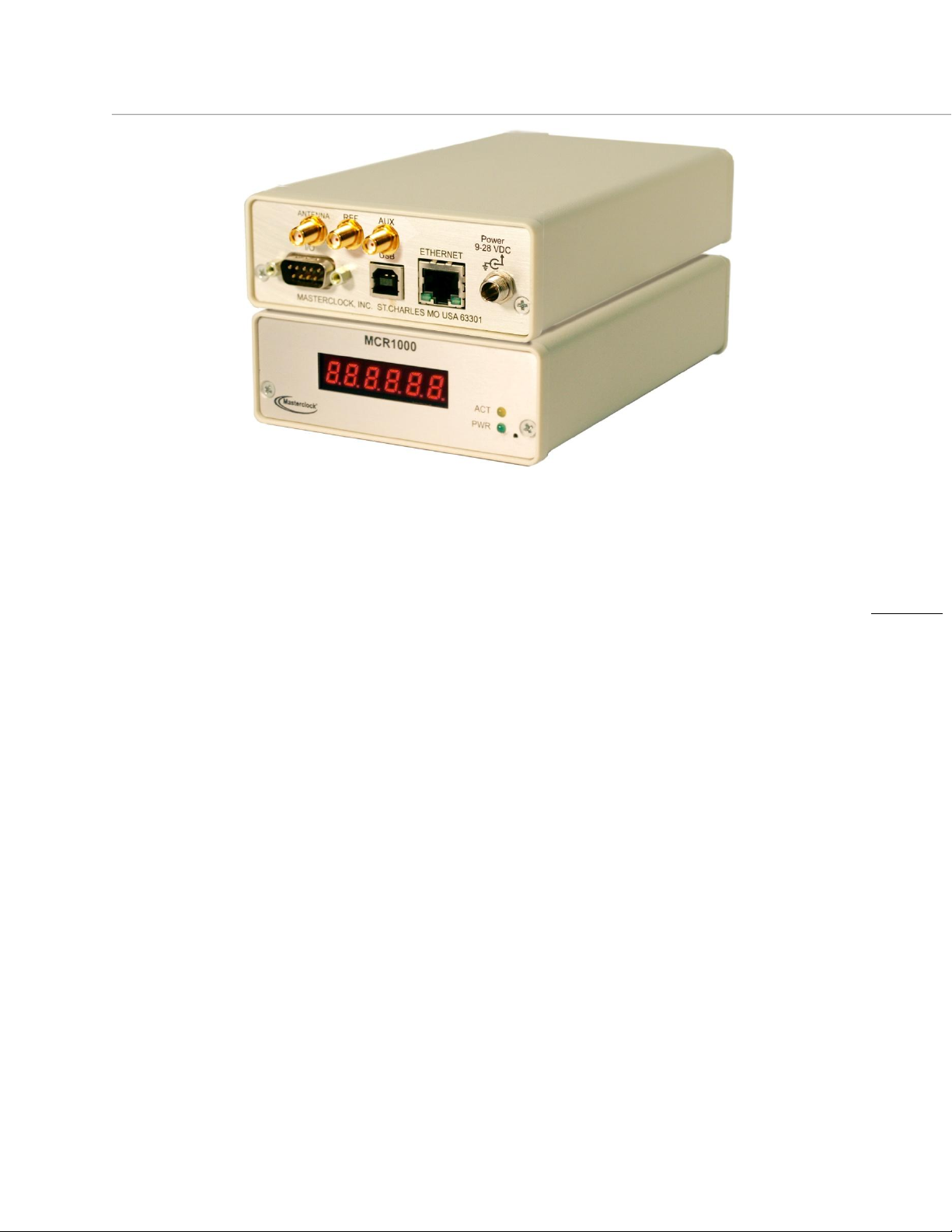
51
SPECIFICATIONS
Communications – Protocols
DHCP/BOOTP (default)
Static IP addressing
Network Time Protocol (NTP)
IPV4 (RFC3171)
SNTP V4 (RFC 2030)
NTP version 3 (RFC 1305)
Unicast (Query) mode
Multicast mode (RFC3171 IANA IPV4
multicast guidelines)
Configuration
WinDiscovery - network discovery and
configuration utility
Windows 2000, XP, 7
Server operating systems:2003, 2008-SP1
Proprietary Packet protocol –
UDP, port 6163
Device password or global password
support
Telnet – TCP, port 23
Communications – I/O
Ethernet (10/100mbps) RJ45, 10/100 baseT
Length of communication
cable (Cat5/5e) 100 meters max
RS-232
(Programming/Configuration Port: DB9 male,
TX, Pin 2
RX, Pin 3
Gnd/Return, Pin 5
The communication settings for the RS-232 port are:
4800 baud, 8 data bits, 1 stop bit, no parity.
Length of communication cable: 3 meters max
(use standard straight thru cable)
The communication settings for the USB port are:
57600 baud, 8 data bits, 1 stop bit, no parity
Cable type: USB-Type B
Length of communication cable: 3 meters max
Serial Port
RS-232 (ASCII):
9600 baud, 8 data bits, one stop bit, no parity
Some models include only one time window.
MCR1000 Specs
Masterclock MCR1000 User Manual – v.2013.08.01
Page 52

52
Timing Characteristics (standard)
Type: Temperature Compensated
Crystal Oscillator (TCXO)
Stability: +/- 1 min/year (0-40 ◦ C)
+/- 3 min/year (41 to 50 ◦ C)
PPS output: Level : 5V TTL [BNC Female]
Pulse width: 40 uSec
(varies with active ref – see options)
Rise time: 10 nS
On-time mark: Active rising edge locks
to current active reference (see options)
Accuracy NTP Client: Network Client
1-10mS typical
10 sec query (default)
Power Requirements
DC input voltage: 9-28 VDC
DC power consumption: <7.5
Caution: No user-serviceable parts are
inside the MCR1000. Please contact the
factory if you require servicing or repair.
Battery
3V,17 mAh, Coin Cell
Maintenance-free
Rechargeable manganese lithium
Panasonic ML1220/V1A
Supplies power to unit for up to 24 hours
Physical
Size: 4.2 x 6.5 x 1.75 in.
Weight: 1 lbs.
Operating Parameters
Operating temperatures: 0 to +50°C
0 to 40C
+/- 1 min/year for Battery
Operating relative humidity: Up to 90%
(non condensing @ 25°C)
Storage temperatures: -40 to +70° C
Storage relative humidity: Up to 90%
(non condensing @ 25°C)
Masterclock MCR1000 User Manual – v.2013.08.01
Page 53

53
Time Code (TC option)
Supported Time Code Formats:
SMPTE/EBU/Film:
(30/25/24 fps), NDF non-drop frame
LTC Linear/Longitudinal, Forward running
User bits with date encoding to Leitch/Masterclock
BiPhase Correction Bit 2: Enabled
Or No User bit date encoding: zero filled
IRIG-B: Format: IRIG-B(00) pulse width coded
(a.k.a. dc level shift, un-modulated)
IRIG-B(12): 1 kHz Amplitude Modulated,
3.3:1 mark to space ratio.
CF (Control Fields): CF =IEEE1344 year encoding
(equivalent to IRIG 200-04)
Or
CF = zero filled (IRIG 200-98, and prior)
SBS (Straight Binary Seconds): enabled
Time Code Reader (TCR option)
Time Code Input
Signal & Connector: Single Ended, Unbalanced
BNC-female
Differential, Balanced
Type: DB-9 Male Pins
Pin 1: PPS
Pin 2: RS232 Tx
Pin 3: RS232 Rx
Pin 4: Common
Pin 5: Ground/Return
Pin 6: Time Code Output
Pin 7: Time Code Input (+)
*Pin 8: Time Code Input (-)
Pin 9: Relay Contact
*For unbalanced signal tie pin 8 to ground.
Input Impedance: >50kOhm
Auto- Detection, Auto-Gain Adjust Range:
SMPTE 24/25/30 fps, NDF: 0.2 to 12 Vpp
IRIG-B00 un-modulated: 0.5 to 12Vp
IRIG-B12, 1khz AM: 0.5 to 8 Vpp
Time Code Generator (TCG option)
Time Code Output Signal & Connector:
Single Ended,
Unbalanced, BNC-female,
Differential,
Balanced
Type: DB-9 Male Pins
Pin 1: PPS
Pin 2: RS232 Tx
Pin 3: RS232 Rx
Pin 4: Common
Pin 5: Ground/Return
Pin 6: Time Code Output
Pin 7: Time Code Input (+)
*Pin 8: Time Code Input (-)
Pin 9: Relay Contact
*For unbalanced signal tie pin 8 to ground.
Output Impedance: 50 Ohm
Output Signal Level: SMPTE
4 Vpp into 600 Ohm,
Masterclock MCR1000 User Manual – v.2013.08.01
Page 54

54
High Stability (HS) Level 2 Option
Crystal oscillator type: OCXO
(Oven Controlled Crystal Oscillator)
Disciplined by the most accurate
active reference available
Stability: <250mS/year
1x10-11 freewheeling with GPS option
referenced & disciplined over several months
10 MHz Reference output (option): 10 MHz
sine wave
2.5 Vpp
50 Ohm
SMA female “REF”
Auxiliary reference output (option): 10 MHz
100 kHz, 10 kHz, 1 kHz, 100 Hz, 10 Hz
or 1 Hz square wave
(AUX) BNC female connector “AUX”
Pulse accuracy: + 200nS post reference loss
Pulse width: 5-20 uSec
GPS Receiver Option
Receiver: Internal,
12 Channel Simultaneous/Parallel
Antenna: Connector External
SMA Female “Antenna”
Frequency: L1, 1575 MHz ± 10 MHz
RF Bias to antenna: 3V DC, center pin
Pulse duration: + 50 uSec pulse when locked
Standard Antenna Option
External pre-amplified
antenna (required): L1 , 1575 MHz ± 10 MHz
Polarization: Right Hand Circular
Impedance: 50 Ohm
Weight: 4.9 oz (140 g)
Dimension: 3.7” diameter x 4.9” length
(96mm x 126 mm)
Voltage: 3-5 VDC (center pin)
Mounting: pipe, M24 x 1.5 internal thread
Power Consumption: @ 22 ma (.24W)
Gain: 32 dB Standard
Temperature: -40 to +85 °C
Antenna Cable Options
Standard antenna cable
(low loss Belden 8219): 50’/15m
Max antenna cable
(low loss Belden 8219): 75’/23m
Max antenna cable
(low loss Belden 9913): 500’/152m
Masterclock MCR1000 User Manual – v.2013.08.01
Page 55

55
Relay Rating
Input contact rating: up to 24 VDC
250 mA max
Type: Jumper Select.
Normally Closed (NC)
or Normally Open (NO)
with Common
DB9 Connector RS-232 I/O Summary
Type: DB-9 Male Pins
Pin 1: PPS
Pin 2: RS232 Tx
Pin 3: RS232 Rx
Pin 4: Common
Pin 5: Ground/Return
Pin 6: Time Code Output
Pin 7: Time Code Input (+)
*Pin 8: Time Code Input (-)
Pin 9: Relay Contact
*For unbalanced signal tie pin 8 to ground.
Programmable Pulse Output (PPO) Option
Type: Rising Edge Triggered, +5V, TTL
Output Impedance: 50 Ohm
Pulse Interval: 100 μSec to 3 days
Pulse Width: 10 μSec to 100 mSec
Accuracy: Same as currently selected
reference source
Masterclock MCR1000 User Manual – v.2013.08.01
Page 56

56
Limited Warranty
This Masterclock product warranty extends to the original purchaser.
Masterclock warrants this MCR1000 against defects in materials and
workmanship for a period of one year from the date of sale. If Masterclock
receives notice of such defects during the warranty period, Masterclock will, at
its option, either repair or replace products that prove to be defective.
Should Masterclock be unable to repair or replace the product within a
reasonable amount of time, the customer's alternate remedy shall be a refund
of the purchase price upon return of the product to Masterclock. This warranty
gives the customer specific legal rights. Other rights, which vary from state to
state or province to province, may be available.
EXCLUSIONS
The above warranty shall not apply to defects resulting from improper or
inadequate maintenance by the customer, customer-supplied software or
interfacing, unauthorized modification or misuse, operation outside of the
environmental specifications for the product or improper site preparation and
maintenance (if applicable).
WARRANTY LIMITATIONS
MASTERCLOCK MAKES NO OTHER WARRANTY, EITHER EXPRESSED OR IMPLIED,
WITH RESPECT TO THIS PRODUCT. MASTERCLOCK SPECIFICALLY DISCLAIMS THE
IMPLIED WARRANTIES OF MERCHANTABILITY OR FITNESS FOR A PARTICULAR
PURPOSE.
In any state or province which does not allow the foregoing disclaimer, any
implied warranty of merchantability or fitness for a particular purpose imposed
by law in those states or provinces is limited to the one-year duration of the
written warranty.
EXCLUSIVE REMEDIES
THE REMEDIES PROVIDED HEREIN ARE THE CUSTOMER'S SOLE AND EXCLUSIVE
REMEDIES. IN NO EVENT SHALL MASTERCLOCK BE LIABLE FOR ANY DIRECT,
INDIRECT, SPECIAL, INCIDENTAL, OR CONSEQUENTIAL DAMAGES, WHETHER
BASED ON CONTRACT, TORT, OR ANY OTHER LEGAL THEORY.
In any state or province that does not allow the foregoing exclusion or
limitation of incidental or consequential damages, the customer may have
other remedies.
HARDWARE SERVICE
You may return your MCR1000 to Masterclock for repair service. Please contact
the factory for RETURN AUTHORIZATION before returning the unit. When you
return your MCR1000 for service, you must prepay all shipping charges,
international duty, and taxes.
Masterclock MCR1000 User Manual – v.2013.08.01
Page 57

57
Masterclock MCR1000 User Manual – v.2013.08.01
Page 58

58
Contact Us
Masterclock, Inc.
2484 West Clay Street
St. Charles, MO 63301 USA
website
www.masterclock.com
USA and Canada
1-800-940-2248
1-636-724-3666
1-636-724-3776 (fax)
International
1-636-724-3666
1-636-724-3776 (fax)
Sales
Technical Support
Masterclock MCR1000 User Manual – v.2013.08.01
 Loading...