

Page 1
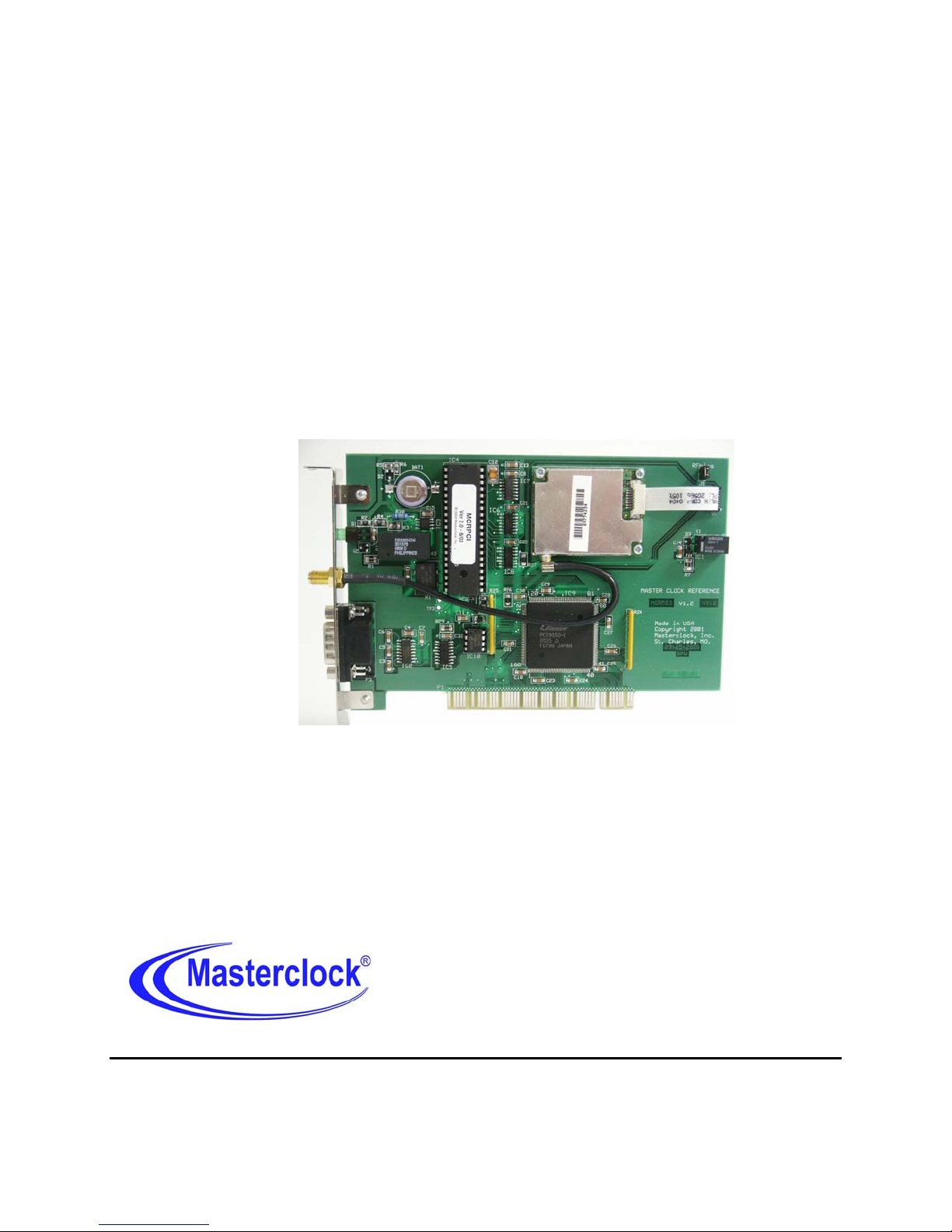
GPSPCI
www.masterclock.com Tel: 636-724-3666 Fax: 636-724-3776
2484 W Clay St, St. Charles MO 63301
GPSPCI 2/7/2008 Rev 1.2.1 a Masterclock, Inc.
USER MANUAL
© Masterclock, Inc. Jan-10 Printed in USA
Page 2

TABLE OF CONTENTS
DISCLAIMER ......................................................................................................................................... c
ADVISORY NOTICE ................................................................................................................... c
INTRODUCTION ................................................................................................................................... 1
GPS Satellites ............................................................................................................................. 1
UTC/Greenwich MEAN Time .................................................................................................... 1
Time Zones & Daylight Saving Time ......................................................................................... 1
INITIAL OPERATION ........................................................................................................................... 1
Operating The GPSPCI For The First Time ............................................................................... 1
Antenna Location ........................................................................................................................ 2
Initial Operations and I/O Connections ...................................................................................... 2
NORMAL OPERATION ......................................................................................................................... 2
FREEWHEELING ................................................................................................................................... 2
Freewheeling/Non Locked LED Indication ................................................................................ 3
HARDWARE – OPERATING ENVIRONMENT .................................................................................. 3
SAMPLE WINDOWS APPLICATIONs & BUS PROTOCOL .............................................................. 3
DB-9 CONNECTIONS............................................................................................................................ 4
RS-232 (NMEA MONITORING PORT) ................................................................................................ 4
PRE-AMPLIFIED ANTENNA ............................................................................................................... 6
Antenna Coaxial Cable ............................................................................................................... 6
PROBLEMS – TROUBLE SHOOTING ................................................................................................. 6
PC BOARD LAYOUT ............................................................................................................................ 7
SPECIFICATIONS .................................................................................................................................. 8
Timing Characteristics ................................................................................................................ 8
Power Supply Requirements ....................................................................................................... 8
Physical ....................................................................................................................................... 8
Operating Temperature ............................................................................................................... 8
PRE-AMPLIFIED Antenna ........................................................................................................ 8
Coaxial Cable .............................................................................................................................. 8
OPTIONS ................................................................................................................................................. 8
LIMITED WARRANTY ......................................................................................................................... 9
Exclusions ................................................................................................................................... 9
Warranty Limitations .................................................................................................................. 9
Exclusive Remedies .................................................................................................................... 9
Hardware Service ..................................................................................................................................... 9
GPSPCI 2/7/2008 Rev 1.2.1 b Masterclock, Inc.
Page 3

DISCLAIMER
The information contained in this document is subject to change without notice.
Masterclock
®
, Inc. (hereinafter Masterclock) makes no warranty of any kind with regard to this
material, including, but not limited to, the implied warranties of merchantability and fitness for a
particular purpose.
Masterclock shall not be liable for errors contained herein or for incidental or consequential
damages in connection with the furnishing, performance, or use of this material.
See important limited warranty information starting on page 9.
ADVISORY NOTICE
CONCERNING GPS SATELLITE SYSTEM
Depending on many factors beyond the control of Masterclock, the signals that are received from the GPS
Satellites are subject to interference, fading, satellite failure and other influences that could cause the
GPSPCI to generate erroneous time and/or date information.
It is the responsibility of the user to determine the adequacy and suitability of this device for the
intended use.
GPSPCI 2/7/2008 Rev 1.2.1 c Masterclock, Inc.
Page 4

INTRODUCTION
The GPSPCI is a PCI card that provides very stable accurate time and date information for a
Windows PC. The card receives reference time information from Atomic Clocks in the GPS
(Global Positioning System) satellites.
GPS SATELLITES
The GPS satellites are operated and maintained by the US Department of Defense and allow for
the precise determination of local time and location at any point on (or above) the Earth. This is
accomplished via the transmission of very accurate timing information from a series of satellites
that provide coverage of the entire planet.
The GPSPCI extracts timing reference from these signals and generates time information to the
PC that is synchronized to within less than 10 microseconds of UTC (Universal Coordinated or
Greenwich Mean Time).
UTC/GREENWICH MEAN TIME
UTC is the local time at the prime reference meridian at Greenwich, England. At a given
location on the planet, local time can be displaced (referenced to UTC) by -11 to +12 hours.
North and South America are from -3 to -11 hours delayed; most of Europe and Africa and all of
Asia and Australia are advanced by +1 to +12 hours.
TIME ZONES & DAYLIGHT SAVING TIME
The GPSPCI provides UTC to the PC’s operating system. Time zone offsets and daylight
savings time are handled as a standard feature of the operating system.
INITIAL OPERATION
Each GPSPC is thoroughly tested with its external antenna prior to shipment. Physical
installation is simply a matter of installing the card into a PCI or ISA bus slot and connecting the
antenna.
OPERATING THE GPSPCI FOR THE FIRST TIME
When the GPSPCI is initially powered up, after having been shipped to a new location, the time
to first fix (time the unit takes to acquire satellites and extract correct time) could be up to 25
minutes although it is typically 5 - 15 minutes. Factors such as atmospheric conditions, antenna
type, antenna location, and antenna cable length will affect the time to first fix.
The GPSPCI will provide time from an internal on-board clock whenever GPS time is not
available. The onboard clock runs from a backup battery in the absence of power from the PC.
GPSPCI 2/72008 Rev 1.2.1 1 Masterclock, Inc.
Page 5

The GPSPCI’s GPS navigation module has its own backup battery that maintains startup data
when the PC is powered down. If, when starting up, the location, time and number of satellites
that the GPSPCI can receive has not changed significantly since last power down, then the
GPSPCI time will be available much faster.
ANTENNA LOCATION
Depending on the type of building where the GPSPCI is located and obstructions that may block
reception of signals from the GPS satellites, the antenna may have to be located where it has an
unobstructed view of the sky. In some cases, this can be accomplished by placing the antenna
next to a window. However, usually it will require mounting it outside of the building or on a
roof. In the worst case, the basic requirement for assured system operation is that the antenna
module has a clear and unobstructed view of the sky for initial satellite acquisition and lock
(generation of time information by the GPSPCI). It is possible that the system will operate
indoors and under other obstructions. However this can only be determined empirically; it is not
guaranteed.
If a longer cable is required, cables of various lengths (up to 500 feet) with pre-amplified
antennas are available from Masterclock. Bringing the GPSPCI up for the first time with an
indoor antenna may prevent or significantly increase the time to first fix.
INITIAL OPERATIONS AND I/O CONNECTIONS
1. Locate the antenna in a suitable area so that the top of the antenna module has a clear view of
the sky. Do not move it until after the GPSPCI has initiated operation (explained below).
2. Connect the antenna coax to the SMA connector on the PC card bracket.
3. The unit first calculates coordinates and distances for acquisition of GPS satellites. The LED
will remain off until satellites are acquired and precise location and timing references are
established.
NORMAL OPERATION
After acquisition of satellites the GPSPCI will begin generating time information and the card
LED will flash once per second.
FREEWHEELING
During continuous operation it is likely that the GPSPCI will experience occasional outages and
loss of satellite reference time. This can be caused by atmospheric and many other outside
conditions which are essentially unavoidable with a simplex system. Such signal losses can last
from a few minutes to hours. When the condition disappears and the unit re-acquires satellite
timing reference, it will automatically resync to the satellite time reference.
GPSPCI 2/72008 Rev 1.2.1 2 Masterclock, Inc.
Page 6
During such outages the GPSPCI will continue to generate time information referenced to the
last available satellite timing information. This mode is referred to as freewheeling. When the
unit first acquires satellite time, it calibrates an internal clock against the incoming atomic time.
During freewheeling the time information will be referenced to this clock and will typically be
accurate to within a few milliseconds over a 24 hour period (if the power is not disconnected).
As is covered in other areas of this instruction book, the freewheeling status is encoded/decoded
by the McrSync software supplied by Masterclock and the operator is given the option of
synchronizing to the time information during the freewheeling state.
The transition to and from freewheeling mode is seamless - it does not interrupt time information
output.
FREEWHEELING/NON LOCKED LED INDICATION
During a freewheeling period the card LED will be off.
HARDWARE – OPERATING ENVIRONMENT
The GPSPCI is not water or moisture proof. Treat it as you would any other delicate electronic
device and do not expose it to water, excessive heat or physical abuse.
SAMPLE WINDOWS APPLICATIONS & BUS PROTOCOL
Included with the GPSPCI (MCRPCI) drivers for Windows, are sample Windows GUI
applications and source code in Visual Basic and Visual C++. These items are provided as-is to
our end users or to developers. Upon running the MCRSETUP.EXE file that is included with
the drivers is run, the sample application and source code is located in the C:\Program
Files\Masterclock\MCR directory.
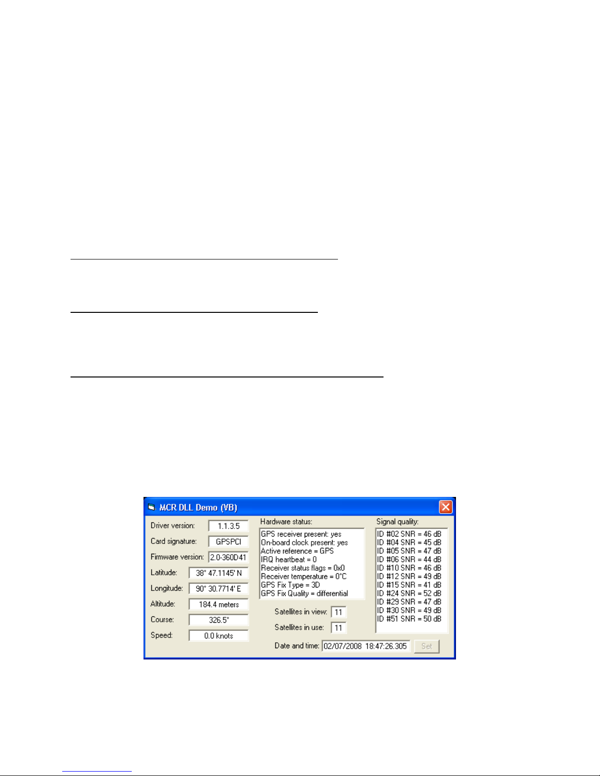
A screen shot of the Visual Basic GUI application is shown below.
GPSPCI 2/72008 Rev 1.2.1 3 Masterclock, Inc.
Page 7

Software application developers, may refer to the MCRPC-GPS ISA/PCI Bus Interface Protocol
Version 1.1.0 which is available for download from the support area of our website.
http://www.masterclock.com/data_files/mcrpc-gps-card-protocolV110.pdf
DB-9 CONNECTIONS
Pin 1 - Pulse Out
TTL-level 100ms active low pulse generated once per second by the GPS receiver. The negative-going edge of the pulse is aligned with UTC
(Greenwich Mean Time) when the receiver has a 3-dimensional GPS satellite fix. This pulse is not available when the GPSPCI is first powered
on. The pulse may become unavailable if the receiver loses GPS satellite fix for an extended period of time. Accuracy of this pulse (when
synchronized to GPS satellite) is nominally +/- 1μs.
Pin 2 – NC
No connect.
Pin 3 – NMEA
NMEA Oututput , (RS-232 transmit signal from GPS)
Pin 4 - NC
No connect.
Pin 5 - Ground
Connect this pin to the ground of any host receiving NMEa information from the GPSPCI via RS-232.
Pin 6, 7, 8 and 9- NC
No connect.
RS-232 (NMEA MONITORING PORT)
• The GPSPCI provides a monitoring port with NMEA 0183 output messages broadcast from
the GPS receiver available once per second, as a RS232 Level on Pin 3 of the DB9
connector. Pin 2 is not connected. Pin 5 is the signal reference/ground.
• Standard NMEA 0183 broadcast messages include :
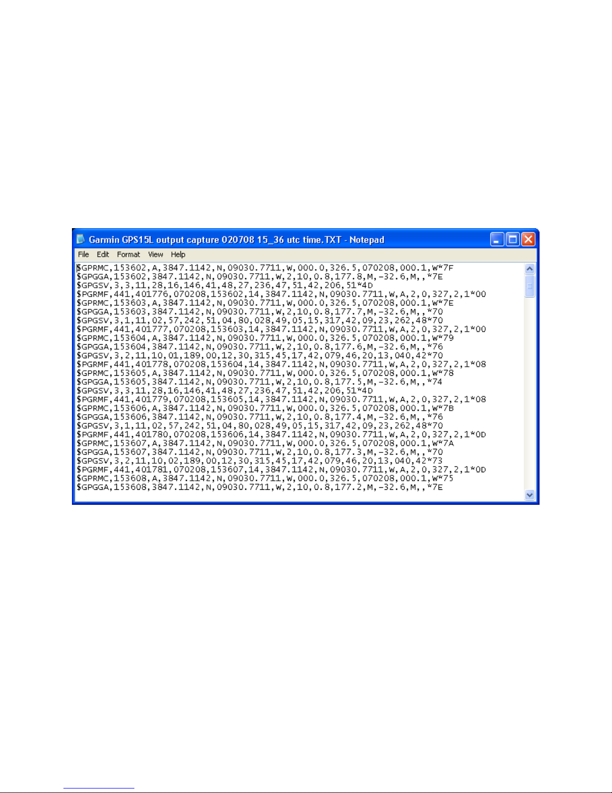
$GPRMC
$GPGGA
$GPGSV
• Additional Proprietary Garmin GPS NMEA messages are included such as
$PGRMF
• The monitoring port requires a null modem RS232 cable along with the following
communication port settings:
Bits per second: 9600
Data bits: 8
Parity: None
Stop bits: 1
Flow control: None
GPSPCI 2/72008 Rev 1.2.1 4 Masterclock, Inc.
Page 8
• This function allows external devices connected via the DB9 connector to operate in a listen
only mode to broadcast NMEA messages from the GPS receiver.
• This monitor function is always enabled at 9600 Baud
(Note: most GPS receivers support a native baud rate of 4800).
• Monitoring may be done using a simple terminal monitor application such as Windows
Hyperterminal or by writing a custom serial port monitoring application. See Hyperterminal
sample below.
• In addition, the GPS receiver PPS (pulse per second) is available on pin 1 of the DB9 for
synchronizing the data.
• Note: this version of the PCB, V1.2, no longer supports full RS232 communications, or the
GPSPCI RS232 protocol specification. Only native NMEA output messages from the GPS
receiver are available. GPS module configuration can no longer be performed via the
RS232 interface.
GPSPCI 2/72008 Rev 1.2.1 5 Masterclock, Inc.
Page 9

PRE-AMPLIFIED ANTENNA
The GPSPCI requires a pre-amplified antenna. It provides 5 VDC via the center pin of the
coaxial for remote power. Warning: Attaching a passive (non pre-amplified) antenna to the
GPSPCI could destroy the GPS receiver module. This is a major repair cost, which is not
covered by warranty.
The unit is tested and shipped with the appropriate cable for the antenna that was ordered.
Should you require a longer antenna cable we recommend that you contact Masterclock so that a
properly matched cable and antenna can be supplied.
Although changing the GPS antenna or coaxial cable is not technically difficult, these changes
are strictly the usre’s responsibility. We neither warrant nor support operation with any hardware
not installed or supplied by us.
ANTENNA COAXIAL CABLE
The coaxial cable should not be crushed, crimped or bent at a sharp angle nor should it be
strained by pulling. Any damage to the cable could result in the GPSPCI not functioning
properly. If the cable is to be coiled for storage, the coil diameter should be at least 6”.
PROBLEMS – TROUBLE SHOOTING
All GPSPCI units are checked for proper operation before shipment. Unless physical damage is
found, the unit has been proven to be functional at the factory.
Please remember for an initial startup at a new location the unit could take up to 30 minutes.
After the unit has acquired satellites at the new location, the startup time is greatly reduced to
anywhere from a few seconds to several minutes.
If the antenna (and coaxial cable) has not been damaged and has an unobstructed view of the
sky, the power connector is properly installed and the front panel LED follows the startup
sequence described earlier (on, off & then on), the unit is working.
If you continue to have problems even after the above precautions have been noted please
contact the factory.
GPSPCI 2/72008 Rev 1.2.1 6 Masterclock, Inc.
Page 10
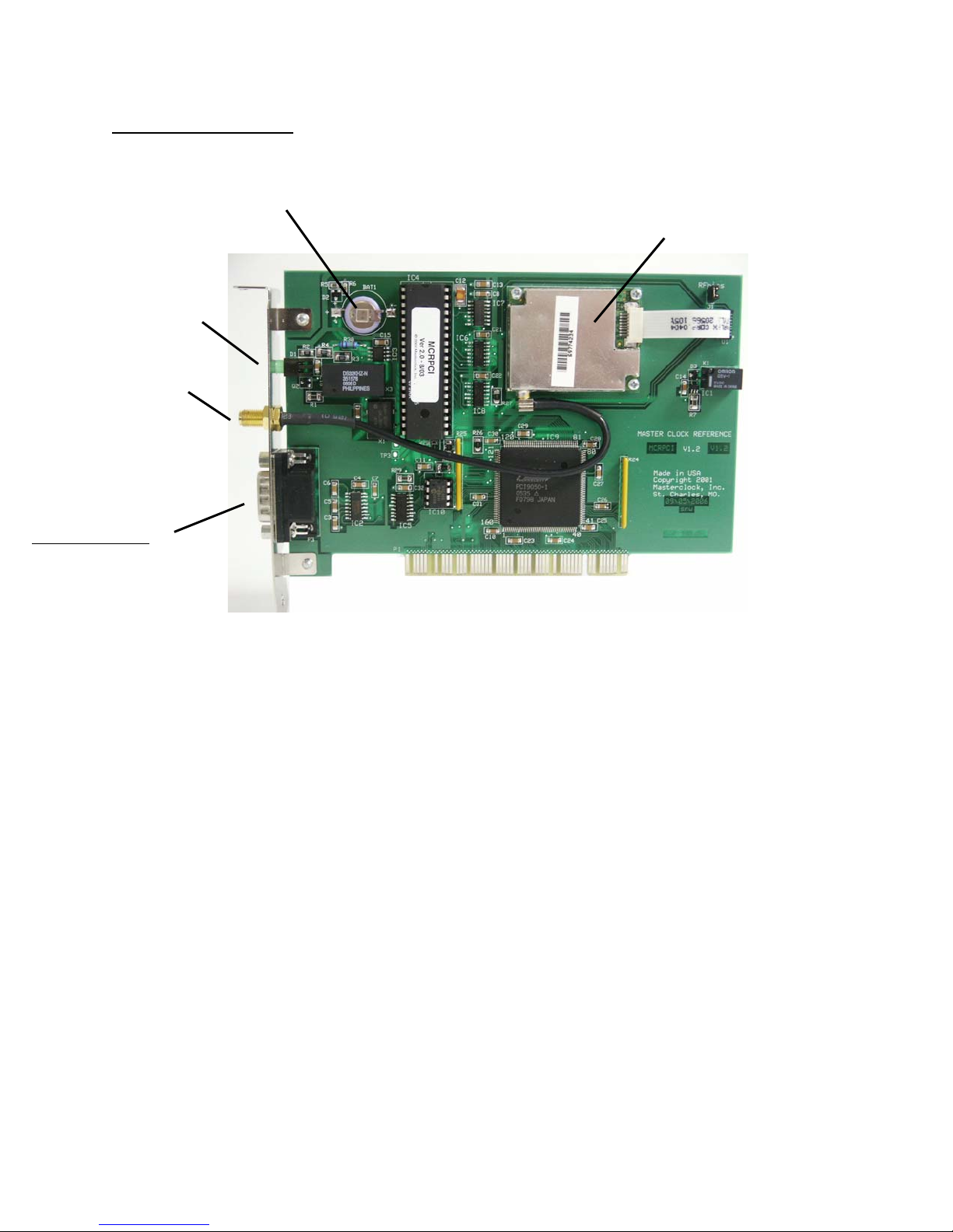
PC BOARD LAYOUT
Rechargeable Battery GPS receiver
GPS Lock Status
Indicator
GPS antenna connector
(SMA female)
DB9 Connector
Pin 1 – PPS, TTL
Pin 3 – NMEA out,
RS232
Pin 5 – Ref/Gnd
module
GPSPCI V1.2
GPSPCI 2/72008 Rev 1.2.1 7 Masterclock, Inc.
Page 11

SPECIFICATIONS
TIMING CHARACTERISTICS
Reference: ........................UTC/GMT (default)
Date
Short term accuracy .........± 10 µs
Long term stability ...........same as GPS atomic clock
POWER SUPPLY REQUIREMENTS
Contains its own CPU and requires only DC power from the PC
PHYSICAL
GPSPCI-PCI ....................1/3 slot AT/PCI card, +5VDC
OPERATING TEMPERATURE
Temperature .....................0 to +70 °C
PRE-AMPLIFIED ANTENNA
Frequency .........................1575 MHz ± 10 MHz
Polarization ......................Right Hand Circular
Impedance ........................50 Ω
Weight ..............................8.3 oz. (235 g)
Voltage .............................3 -5 VDC
Power Consumption .........0.24W (@ 20 mA)
Gain ..................................26 dB Standard
Temperature .....................-40 to +70°C
Connector .........................SMA female
COAXIAL CABLE
Type 51 Ω low loss - RG-58A/U (Belden 8219 or equivalent)
SMA-male connectors up to 75’/23m
51 Ω low loss – Belden 9913 or equivalent up to 500’/152m
OPTIONS
SYNC-NTP Software NTP Time Server Software for use with
GPSPCI, MCRPCI, and TCR500-PCI PC cards.
ANTENNA OPTIONS
See website for details www.masterclock.com
GPSPCI 2/72008 Rev 1.2.1 8 Masterclock, Inc.
Page 12

LIMITED WARRANTY
This Masterclock Inc. (hereinafter Masterclock) product warranty extends to the original
purchaser.
Masterclock warrants the GPSPCI against defects in materials and workmanship for a period of
one year from date of sale. If Masterclock receives notice of such defects during the warranty
period, Masterclock will, at its option, either repair or replace products that prove to be
defective.
Should Masterclock be unable to repair or replace the product within a reasonable amount of
time, the customer's alternate remedy shall be a refund of the purchase price upon return of the
product to Masterclock. This warranty gives the customer specific legal rights. Other rights,
which vary from state to state or province to province, may be available.
EXCLUSIONS
The above warranty shall not apply to defects resulting from improper or inadequate
maintenance by the customer, customer-supplied software or interfacing, unauthorized
modification or misuse, operation outside of the environmental specifications for the product or
improper site preparation and maintenance (if applicable).
WARRANTY LIMITATIONS
MASTERCLOCK MAKES NO OTHER WARRANTY, EITHER EXPRESSED OR IMPLIED,
WITH RESPECT TO THIS PRODUCT. MASTERCLOCK SPECIFICALLY DISCLAIMS
THE IMPLIED WARRANTIES OF MERCHANTABILITY OR FITNESS FOR A
PARTICULAR PURPOSE.
In any state or province which does not allow the foregoing disclaimer, any implied warranty of
merchantability or fitness for a particular purpose imposed by law in those states or provinces is
limited to the one-year duration of the written warranty.
EXCLUSIVE REMEDIES
THE REMEDIES PROVIDED HEREIN ARE THE CUSTOMER'S SOLE AND EXCLUSIVE
REMEDIES. IN NO EVENT SHALL MASTERCLOCK BE LIABLE FOR ANY DIRECT,
INDIRECT, SPECIAL, INCIDENTAL, OR CONSEQUENTIAL DAMAGES, WHETHER
BASED ON CONTRACT, TORT, OR ANY OTHER LEGAL THEORY.
In any state or province that does not allow the foregoing exclusion or limitation of incidental or
consequential damages, the customer may have other remedies.
HARDWARE SERVICE
You may return your GPSPCI to Masterclock for repair service. Please contact the factory for
return authorization before returning the unit.
GPSPCI 2/72008 Rev 1.2.1 9 Masterclock, Inc.
 Loading...