

Page 1
What’s New
Page 2

Mastercam® X6 What’s New
Date: October 2011
Copyright © 2011 CNC Software, Inc.— All rights reserved.
First Printing: October 2011
Software: Mastercam X6
TERMS OF USE
Use of this document is subject to the Mastercam End User License Agreement. A copy
of the Mastercam End User License Agreement is included with the Mastercam product
package of which this document is part. The Mastercam End User License Agreement
can also be found at:
www.mastercam.com/legal/licenseagreement/
Page 3
What’s New in Mastercam X6
General System Enhancements
64-bit Support
Mastercam X6 is available as a 64-bit application, which lets you take full advantage of your 64-bit hardware and
operating systems.
Level Manager Improvements
These improvements focus on level manipulations that are especially useful on parts imported from other
systems where levels were not used. These enhancements will assist you in organizing the data so you can
create toolpaths or perform other edits to the model.
On the Change Levels and Attributes dialog boxes, you now have control over the visibility of new levels you
create for geometry. You can force new levels to be visible or invisible once the geometry is moved or copied.
In addition, you can control which level is the Main level using the arrow keys in the Level Manager. Select the
Arrow keys set main level checkbox and use the arrow keys to move through the level list and change your
Main level.
What’s New in Mastercam X6 - Page 1
Page 4
Quick Mask for Groups
This new Quick Mask provides a shortcut to the Groups Manager dialog box for geometry selection. Instead of
selecting All, Group Manager, you can simply click this toolbar button and then double-click to quickly select all
geometry assigned to a group.
Override Solid Face Color on Import
This new option, located in File, Open, Options or Settings, Configuration, Converters, forces the colors of
imported solids to take on the current system color. This overrides any face or feature colors that have already
been applied to a solid.
What’s New in Mastercam X6 - Page 2
Page 5
DWFx Import
Mastercam X6 now supports the .DWFx file format, which is an Autodesk file format based on the XML Paper
Specification (XPS) format from Microsoft. DWFx files can also be opened directly within Microsoft’s XPS Viewer.
File Translator Updates
• ACIS: R22
• Autocad: Can now take .DWFX files
• CATIA V5: R21
• KeyCreator: 2011
• Parasolids: 23
• ProE/Creo: Wildfire5/Creo 1.0
• SolidEdge: ST4
• SolidWorks: 2012
Design Enhancements
Intersecting and Trimming Solid Edges
Mastercam’s AutoCursor now recognizes intersections between wireframe geometry and solid edges without
creating additional geometry first.
You can also trim or extend wireframe geometry to solid edges using the existing Mastercam trimming
functions. Some examples include:
• Using Edit, Trim/Break, Trim/Break/Extend to trim the wireframe to one, two, or three solid edge
entities.
• Selecting Edit, Trim Many to use a solid edge as the trim boundary
• Using Edit, Trim/Break, Break at Intersection to break wireframe where it intersects solid edges.
Solid Trim to Surface
The Trim Solid dialog box includes two new options for trimming solids to surfaces. These options give you
more control over your trimming results.
What’s New in Mastercam X6 - Page 3
Page 6

Remove Solid History
The functionality from the NoHist C-Hook is now incorporated into the main Mastercam product. This function
strips the list of operations or features from a solid model, leaving it as a "brick" in the Solids Manager. You can
use this to prevent changes and protect your model. You can access this function by choosing Solids, Remove all
solid history operations
Xform Fit
Xform Fit is a new function in Mastercam X6 that “nests” geometry along a vector, making it easier for you to
make multiple copies between two defined points without knowing the exact distance between the points. This
can be helpful when fitting parts between clamps and fixtures.
Trim/Divide Support for Splines
Mastercam X6 includes support for splines in Xform Divide for trimming curves or curves to be trimmed.
All and Only Mask – Arc Sweep
The All and Only masks now include the option to select arcs and circles with a sweep angle in mind. This is
another way to speed up your geometry selection. For example, selecting a 0.5” diameter can be limited to only
circles when diameter and arc sweep are used together. You can set these options on the Miscellaneous page of
the Select All and Select Only dialog boxes.
What’s New in Mastercam X6 - Page 4
Page 7
Analyze Point or Area Using Feet/Inches
In the following Analyze functions, you can now see results in inches, feet/inches decimal, feet/inches fractional,
millimeters, centimeters, or meters:
• Position
• Volume/Area, 2D Area
• Volume/Area, Surface Area
• Volume/Area, Solid Properties
General Mill/Router Enhancements
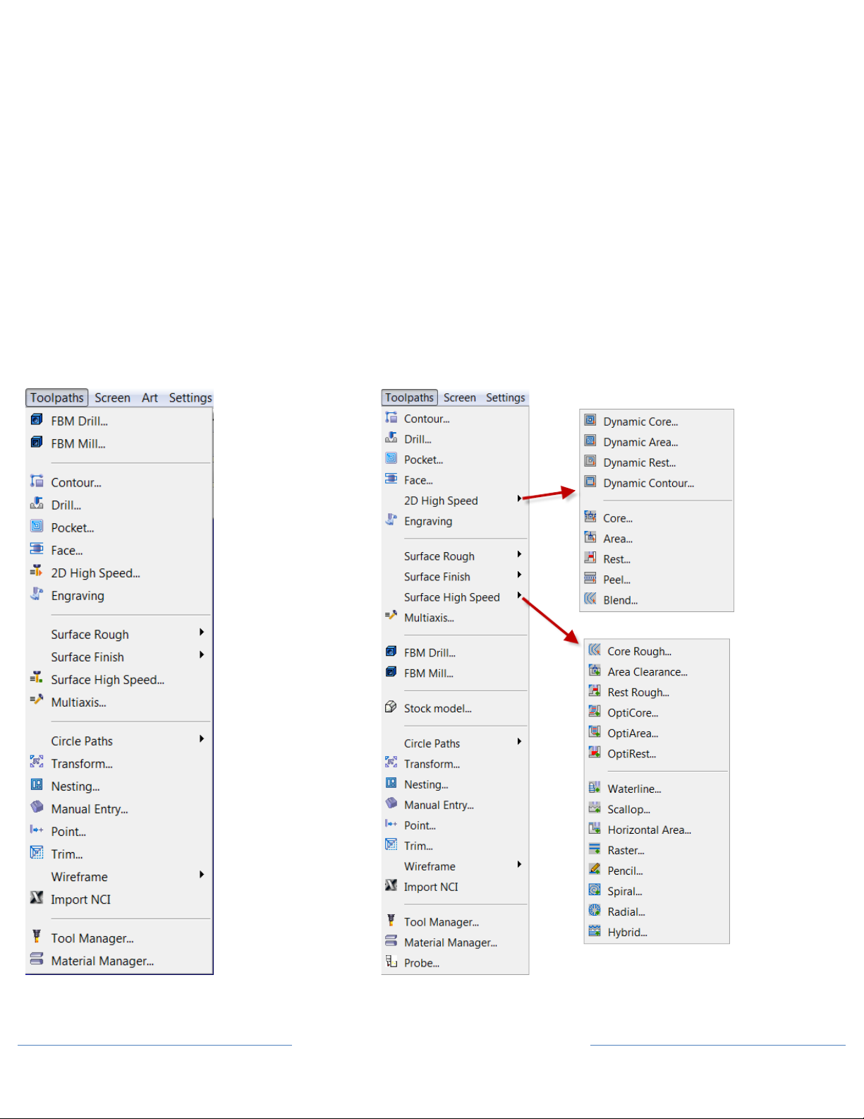
Mill/Router Toolpath Menu Reorganization
By restructuring the Mill and Router toolpath menus, you now have easier, faster access to all 2D and 3D high
speed toolpaths.
Mastercam X5 Mill Mastercam X6 Mill
What’s New in Mastercam X6 - Page 5
Page 8
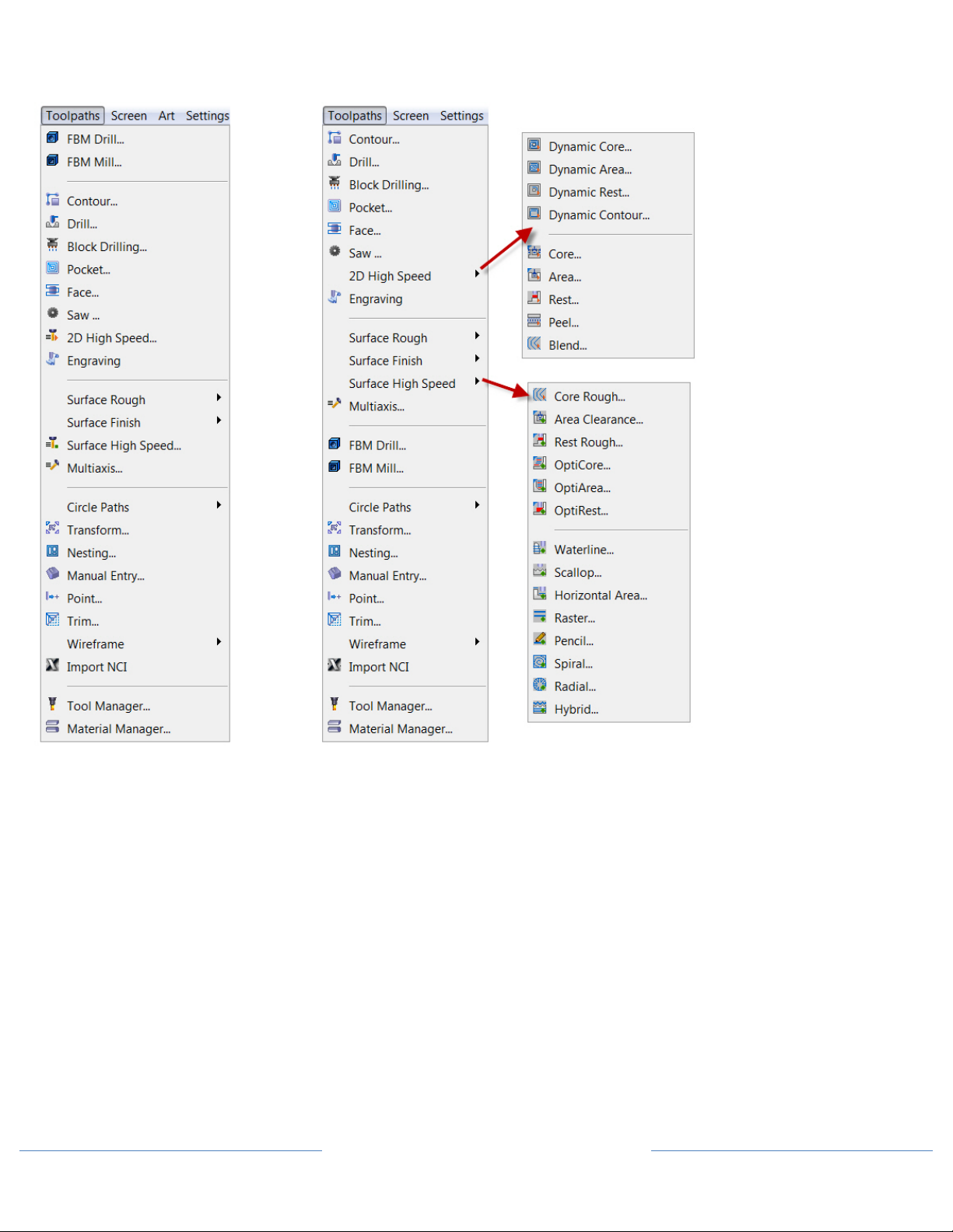
Mastercam X5 Router Mastercam X6 Router
What’s New in Mastercam X6 - Page 6
Page 9

Stock Model
In Mastercam X6, the stock model for Mill 2-axis through 5-axis toolpaths is now a separate entity in the
Toolpath Manager with more power and flexibility than ever before.
You can generate an initial stock model by choosing Toolpaths, Stock model from the Mastercam menu. The
stock model is fully associative and has parameters that can be edited at any time similar to toolpath or solid
operations. The stock model operation is marked dirty and requires a regen if you make changes to the stock
model parameters or any toolpath the stock model is referencing.
Once created, you can use stock model operations to:
• Verify stock
• Define stock for rest machining
• Visualize stock
• Generate stock model compares
Note: If you have activated multi-threaded processing for your configuration, Mastercam generates stock model
operations as multi-threaded processes.
In the Stock Model dialog box, the Stock Definition page lets you create a name for the model, select a color, and
set the basic shape parameters. Solids, mesh entities, surfaces (even single surfaces), STL files, and other stock
models can all provide the basis for the new stock model. You can also pull in any values you entered in the
Stock Setup page of the Machine Group Properties dialog box.
What’s New in Mastercam X6 - Page 7
Page 10
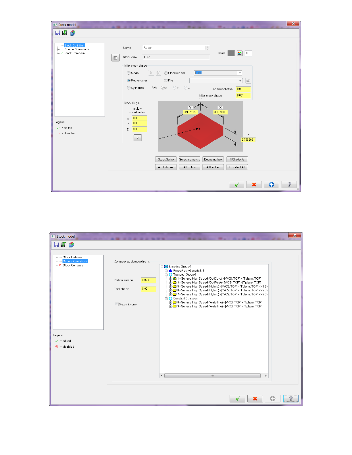
The Source Operations page is where you select the source operations to process against the defined stock in the
stock model operation. Use [Ctrl+click] and [Shift+click] methods to select any combination of operations in
the tree, including those from different machine groups.
What’s New in Mastercam X6 - Page 8
Page 11
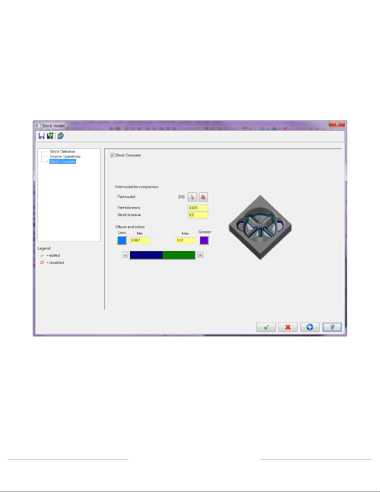
In addition, you can use the stock model to display leftover material. Using the Stock Compare page, follow these
general guidelines:
• Select the Stock Compare checkbox.
• Use the Select button to return to the graphics window and select the part model entities to use in the
comparison against the stock model.
• Define the tolerance for the stock model compare.
• Enter a value for stock to leave on the part model.
• Set the minimum/maximum offset values and colors for the compare results.
For more details on using this function, please click the Mastercam Help button at the bottom of the dialog box.
What’s New in Mastercam X6 - Page 9
Page 12

The following picture shows stock model comparison results:
Toolpath operation Stock model result from operation
Bull-Nose Tool Support in Dynamic and Optimized Roughing Toolpaths
Toolpath motion in the following Mill and Router toolpaths is now optimized for bull-nose tools as well as flat
endmills. If you select a bull-nose tool, the toolpath strategy alters the tool’s trajectory to prevent any remaining
material cusps.
• 2D HST: Dynamic Core, Dynamic Area, Dynamic Rest
• 2D HST: OptiCore, OptiArea
Coolant Icons in Toolpath Manager
These new icons let you quickly see whether coolant is on or off for each toolpath. These icons are only used by
Mill and Lathe toolpaths. Clicking on the icons takes you to the toolpath parameters so you can make changes if
necessary.
What’s New in Mastercam X6 - Page 10
Page 13

Mill/Router Tool Improvements
Improved Tool Preview Zoom Functionality
A new Zoom button on the Define Tool dialog box quickly focuses on the tool’s cutting portion and lets you see
details on very small shaded tools. Clicking the Zoom button again returns you to the Fit view. The new preview
makes it much easier to see the cutting portion of the tool and reduces the chance of errors.
Figure 1 - The Define Tool dialog previewing a long tool with a small corner radius
Figure 2- The Define Tool dialog previewing a long tool with a small corner radius in zoom mode
What’s New in Mastercam X6 - Page 11
Page 14

New Taper Section for Lollipop Tools
The lollipop tool shape is often used for undercutting operations. In order to make better use of the tool in these
situations, it’s common to have a tapered section on the shank of the tool. Rather than creating a custom tool or
representing your tool as a short shanked tool with a tapered holder, you can now define the taper in the Define
Tool dialog box.
Holder Support Added to TOOLDB
In Mastercam X6, you can now read tool holders from the TOOLDB (tool database) file. The HOLDERS file format
is still supported for backwards compatibility. You can use the Save to library function on the Holder toolpath
parameter page to convert your HOLDERS file into a TOOLDB file. You can also save individual holders to an
existing TOOLDB file.
Besides saving individual holders to a library, one of the most important benefits is that as new TOOLDB files
become populated with holder data, you can access to them through a new library without waiting for a new
software release.
Note:
Saving individual holder components to an existing library is only supported when using the new TOOLDB
file.
What’s New in Mastercam X6 - Page 12
Page 15

Mill/Router 2D Enhancements
New 2D HST Region Chaining
The new region chaining options in Mastercam X6 give you more control over areas to machine and areas to
avoid in your 2D HST toolpaths. After you select your initial chains, the Chain Options dialog box lets you adjust
your machining areas.
2D HST Blend Mill Compensation
Cutter compensation options are now available in 2D HST Blend Mill toolpaths. The options include left, right,
inside, and outside. Tip compensation and stock to leave on walls are also supported.
What’s New in Mastercam X6 - Page 13
Page 16

2D HST Dynamic Toolpath Improvements
The 2D HST Dynamic toolpaths (Core, Area, Rest, and Contour) include several enhancements in Mastercam X6:
Variable Toolpath Radius
The 2D HST Dynamic toolpaths currently use the toolpath radius value as a hard value for both arc on/off
motion and sharp corner smoothing. At times, the tool cannot fit into narrow channels or between islands due to
the toolpath radius size. Instead of using a smaller toolpath radius to fit into these areas, which limits the
efficiency of the arc on/off motion, these toolpaths now automatically adjust the toolpath radius in these areas.
This allows the tool to fit into tight areas and mill deeper in sharp corners. You can enter a minimum toolpath
radius on the Cut Parameters page.
Without variable radius With variable radius
Zigzag Motion Support
With this new feature, you can now use zigzag toolpath motion for open passes to optimize your dynamic
toolpaths. The toolpaths use the toolpath radius to smoothly exit and enter material during direction changes.
When machining closed contours, the toolpath defaults to climb milling.
Note: This change does not apply to Dynamic Contour toolpaths.
Climb millling Zigzag milling
What’s New in Mastercam X6 - Page 14
Page 17

Outside Approach Control
Dynamic Facing, Core, and Contour toolpaths now include the ability to specify which side of the block the tool
approaches from. You can use this functionality to avoid over-travel conditions when large parts might be taking
up most of the travel in one direction.
The following pictures illustrate the approach options:
What’s New in Mastercam X6 - Page 15
Page 18

2D Contour Smoothing
In Mastercam X6, the 2D Contour toolpath now creates smooth motion in sharp corners. Removing sharp
corners reduces tool wear and makes your tool motion more efficient. You can enter an Internal corner rounding
radius on the Cut Parameters page. Corner smoothing also supports multi passes.
Without corner rounding With corner rounding
Adjust Start/End for Peel Mill and Dynamic Contour
Peel Mill and Dynamic Contour toolpaths support lead in/out for their finish passes. This additional functionality
allows the finish pass lead in/out to be extended or shortened without having to create a separate operation or
having to modify geometry. This functionality is in addition to the entry/exit extensions already supported in
the peel mill roughing motion defined on the Cut Parameters page.
What’s New in Mastercam X6 - Page 16
Page 19

Mill/Router 3D Enhancements
New OptiRest Toolpath
Mastercam’s latest 3D HST toolpath is OptiRest, which performs rest milling operations to remove remaining
material with optimized roughing motion. It is the first Mastercam toolpath to take advantage of the new stock
model functionality for defining stock removal areas. In addition, containment boundaries are required for this
toolpath.
Toolpath motion Gray = stock model, purple = OptiRest machining area
What’s New in Mastercam X6 - Page 17
Page 20

3D HST Hybrid Finish Filler Passes
3D HST Hybrid toolpaths now maintain all of the Z level cuts in the steep areas of your part and fills in the
shallow areas with scallop motion. It combines the best of both worlds with waterline (constant Z) motion and
scallop where needed. In X5, shallow areas would have resulted in 3D collapse (essentially scallop) motion for
all Z cuts at that level. Now you can have both waterline and scallop motion at the same Z level so the entire part
is cut.
You can control this motion on the Cut Parameters page for Hybrid toolpaths. Use the 3D passes section to
control how the toolpath handles shallow areas. Select Preserve Z passes to keep all waterline motion in the
toolpath. Then select a method for handling the boundaries between steep and shallow areas from the dropdown.
• Closed offsets: The boundaries are treated as closed chains when calculating the 3D collapse motion.
• Upper to lower: The boundaries are treated as closed or open chains that collapse from the highest Z
value to the lowest.
• Lower to upper: The boundaries are treated as closed or open chains that collapse from the lowest Z
value to the highest.
OptiRough Toolpath Split into OptiCore and OptiArea
The current OptiRough toolpath uses a checkbox to control whether you use an area pocketing approach or a
core from outside approach. In X6, OptiRough is split into two dedicated toolpaths for areas and cores –
OptiArea and OptiCore. Both toolpaths can be found on the Surface High Speed Toolpaths menu.
What’s New in Mastercam X6 - Page 18
Page 21

Multiaxis Enhancements
Blade Expert
Multi-bladed parts are used in many industries, including marine, aeronautical, energy, and automotive.
Machining these complex shapes usually requires special multiaxis equipment, but Mastercam’s new Blade
Expert is specifically designed to generate the necessary toolpaths for many of the different multi-blade
configurations.
Blade Expert is designed to generate the toolpaths for the following segments of the multi-blade workflow:
• Roughing between the blades
• Semi-finishing the blades
• Finishing the blades
• Finishing the hub
Multi-bladed parts typically include the following key areas:
1. Hub surface - revolved floor surface that the blades sit on.
2. Blade surface - usually free-form surfaces with a double curved shape.
3. Blade leading edge - the suction side for the transported medium. For impellers and blisks, it is usually
rounded. The leading edge is usually closest to the center of the hub.
4. Blade trailing edge - the exhaust side. For an impeller, this side is not rounded. The trailing edge is
usually closest to the circumference of the hub.
5. Fillets - part of the blade. They guarantee a rounded connection between the blade and the hub. The
fillets can have a constant radius as well as a dynamic radius.
6. Splitter - found on impeller geometries. It is a shorter blade, similar to the main blades, and located
between the two main blades. The leading edge can be horizontal (as in the picture above) or tilted.
7. Shroud surface - the top surface of the blades and the splitter. It is usually an overturned surface from
the stock, but can also be a free- form surface.
Note: Blade Expert is a Mastercam add-on that must be purchased separately. You must own Mill Level 3 or
Router Pro to purchase the add-on, but you do not need to own the Multiaxis add-on.
What’s New in Mastercam X6 - Page 19
Page 22

5-axis Stock Model Toolpath Trimming
For any of the multiaxis toolpaths in the Classic toolpath family, you can trim your toolpath to the new stock
model. Trimming to stock reduces the amount of time the tool is not in contact with the material.
Lathe Enhancements
Improved Cutoff/Pickoff Operations
Mastercam X6 Lathe includes improvements to the cutoff and pickoff operations. Choose Toolpaths, Misc Ops,
Pickoff/Pull/Cutoff to access this function.
Note: You must have an updated post processor to use this function. Please contact your Mastercam Reseller for
more information.
What’s New in Mastercam X6 - Page 20
Page 23

Use this dialog box to translate geometry and create a part transfer operation from the main spindle to the sub
spindle and/or a bar pull operation prior to a cutoff toolpath. You can choose to just create the geometry
without creating any operation, or you can create the geometry and the following types of operations:
• Pickoff, Bar pull, Cutoff
• Pickoff, Cutoff
• Pickoff
• Bar pull
The following conditions must be met to use this function:
• The red Insert Arrow must be in a Lathe machine group.
• The machine group must have stock defined in a fixed spindle, or both spindles, and the chuck jaws
defined for both spindles. If both spindles can move in Z, the spindle not containing stock will be assumed
to be the pickoff spindle. If both spindles contain stock in this case, the right spindle is assumed to be the
pickoff spindle.
• A cutoff operation must exist in the currently active operation library.
For more details on using this function, please click the Mastercam Help button at the bottom of the dialog box.
Variable Depth Roughing
This new roughing parameter allows you to vary the point that the surface contacts the tool insert to prevent
notching and improve tool life. The depth can vary up to 25% of the cut depth. A positive value results in an
upward cut and a negative value results in a downward cut.
• The passes alternate between angled and straight.
• If the cut length is less than three times the cut depth, a straight cut is made instead of an angled cut.
• In flat areas, a straight cut is made instead of an angled cut.
• One way and zigzag cuts are both supported, as well as ID, OD, Face, Back and Angled.
What’s New in Mastercam X6 - Page 21
Page 24

Finish Toolpaths - Up/Down Cutting Strategy
Lathe finish toolpaths are now optimized by detecting and finishing up (flats) and down (walls) cut regions of
the profile using a single chain.
Note: This motion uses the following terms:
• Walls: other terms include steep, down cut and faces. Walls are cut in a vertical or downward direction.
• Flats: other terms include shallow, non-down cut and diameters. Flats are cut in a horizontal or upward
direction.
• Transition angle: the deviation from the wall angle before the geometry is considered to switch from a
Wall to a Face. A 90 degree transition angle implies that all regions of the geometry are considered Wall
geometry. A 10 degree transition when cutting OD implies that geometry with an angle between 80 and 100
or 260 and 280 degrees is considered to be Wall geometry.
What is considered a wall or flat depends on the specified transition angle and finish direction. On the Down
Cutting Parameters dialog box, you can choose from the following cutting strategies:
• Walls: Down cut Walls only using a down cut strategy.
• Flats: Machine Flat areas only in the chain direction.
• Walls then Flats: Machine all walls (wall strategy), followed by all flats (flat strategy).
• Flats then Walls: Machine all flats, followed by all walls.
What’s New in Mastercam X6 - Page 22
Page 25

Canned Rough and Finish Improvements
Mastercam X6 Lathe includes several improvements to canned rough and finish toolpaths:
• Added clearance options to the canned rough operation parameters to extend the chain for tool
clearance.
• Added parameters to shorten the start and end of the chain in the Lead in/out dialog. This is especially
useful when cutting on the OD towards the chuck. The chain can be shortened to prevent the tool from
hitting the chuck.
• Canned finish operations now use the cutter comp options from the canned rough operation. The cutter
comp options from the canned rough operation will be displayed but disabled.
• Support for Type I and Type II canned cycles
• Added a clearance value for canned finish. The start point used in canned finish is shifted above the part
by the clearance. Then at the end of canned finish, the tool moves up and away from the part on the move
to the start point.
Facing and Canned Groove Toolpaths - Optional Finish Feed/Speed
Facing toolpaths in Mastercam X6 Lathe offer additional feeds and speeds specifically for finish passes. This
functionality has also been added to Canned Groove toolpaths.
Facing Corner Break
The new Corner button on the Face parameters tab provides options for adding a chamfer or radius to the edge
of a part. The break is only allowed on the “leading” corner of the face (the first corner encountered moving in
the direction of the toolpath).
What’s New in Mastercam X6 - Page 23
Page 26

Grooving Toolpath Improvements
For groove roughing toolpaths, you now have the option to adjust the plunge and retract feed rates on the first
plunge cut.
What’s New in Mastercam X6 - Page 24
Page 27

Groove finishing toolpaths support undercut removal and negative stock to leave.
Finish Tool Inspection
Tool inspection is available in Finish toolpaths. This function had previously only been available in Rough and
Groove toolpaths. You can establish points during operations where the machine can be programmed to a
specific position and stop to allow you to perform tool inspections. You can set the conditions on which the tool
inspections are performed, such as:
• After a number of passes
• After a specified cut length
• After a specified cut duration
Additional options let you control whether a tool inspection can occur during a pass or near the start or end of a
pass. You can also use reference points to get the tool in and out of the cut, and send the tool to a selected point
or to the home position for the tool inspection position.
What’s New in Mastercam X6 - Page 25
Page 28

Rough Remaining Stock
This new option adjusts your roughing toolpaths to minimize air cuts by recognizing remaining stock. You can
then click Adjust Stock to choose your machining area.
What’s New in Mastercam X6 - Page 26
Page 29

C-Axis Face Contour and Face Drill – Support for Plane Rotation
The C-Axis Face Contour and Face Drill toolpaths now support plane rotation when using Y-axis motion.
Wire Enhancements
New AutoSync Rails
This function has been improved in Mastercam X6 Wire to create better synchronized wirepath chains from
selected solids and surfaces. Choose Create, Autosync Rails to access the new functionality.
What’s New in Mastercam X6 - Page 27
Page 30

Wirepath Editor Improvements
The Mastercam Wirepath Editor now supports 4-axis Direct wirepaths.
What’s New in Mastercam X6 - Page 28
Page 31

Control Definition Option to Force Wire Taper to Vertical
Mastercam X4 introduced a Reset Taper option on the Leads page that allowed you to force the wire back to a
vertical position when the Max lead out distance is used. In X6, a new option in the Control Definition allows for
this Reset Taper mode to be always active. Some machines require the wire to move to a vertical position on a
change-over from G41 to G42 compensation.
What’s New in Mastercam X6 - Page 29
Page 32

Page 33

Page 34

Attention! Updates may be available.
Go to Mastercam.com/Support for the latest downloads.
671 Old Post Road
Tolland, CT 06084 USA
www.mastercam.com
 Loading...