

Page 1

Basic 2D
Machining
Page 2

Page 3

mastercam x getting started series tutorials
Basic 2D
Machining
October 2010
Be sure you have the latest information!
Information might have been changed or added since this document was
published. Contact your local Reseller for the latest information.
Page 4

II • BASIC 2D MACHINING
Mastercam® X5 Basic 2D Machining
Date: October 2010
Copyright © 2010 CNC Software, Inc.— All rights reserved.
First Printing: October 2010
Software: Mastercam X5
Part Number: X5-PDF-TUT-2M
TERMS OF USE Use of this document is subject to the Mastercam End User License Agreement. A
copy of the Mastercam End User License Agreement is included with the
Mastercam product package of which this document is part. The Mastercam End
User License Agreement can also be found at:
www.mastercam.com/legal/licenseagreement/
Page 5

Contents
Introduction ...................................................................... 1
1. Drilling Holes............................................................... 5
III
Tutorial Goals................................................................................... 2
Before You Begin............................................................................. 2
If You Need More Help.................................................................... 3
Additional Documentation.............................................................. 4
Lesson Goals.................................................................................... 5
Exercise 1: Assigning a Machine Definition.............................. 5
Exercise 2: Setting Up Stock ....................................................6
Exercise 3: Drilling Four Holes ..................................................8
2. Roughing Outside the Part ......................................... 15
Lesson Goals..................................................................................15
Exercise 1: Creating a Dynamic Mill Toolpath......................... 15
Exercise 2: Viewing Your Toolpaths........................................ 23
Exercise 3: Creating a Contour Toolpath................................. 23
3. Machining Inside the Part.......................................... 29
Lesson Goals..................................................................................29
Exercise 1: Creating a Dynamic Mill Toolpath......................... 29
Exercise 2: Creating a Slot Mill Toolpath ................................ 34
4. Previewing Toolpaths ................................................ 39
Lesson Goals..................................................................................39
Exercise 1: Backplotting All Toolpaths.................................... 39
Exercise 2: Verifying All Toolpaths.......................................... 42
5. Posting Toolpaths ...................................................... 45
Lesson Goals..................................................................................45
Exercise 1: Posting All Toolpath Operations ........................... 45
Page 6

IV • BASIC 2D MACHINING
Conclusion...............................................................................................48
Post Processing Summary: Sending NC Files to Machine ....... 48
Page 7
INTRODUCTION
This tutorial focuses on applying several mill toolpaths to a part previously designed in Mastercam.
The tutorial then guides you through the steps to take that toolpath data and create NC code to
machine the part.
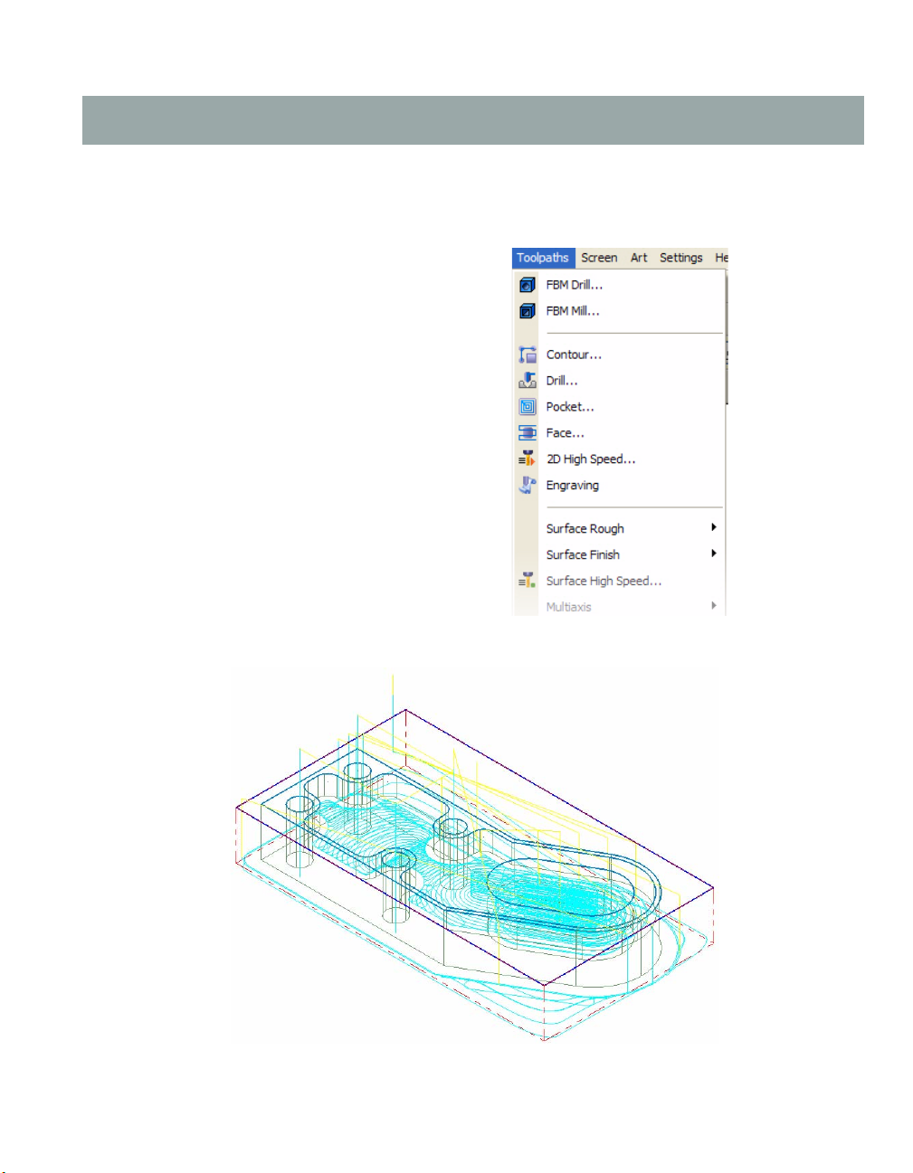
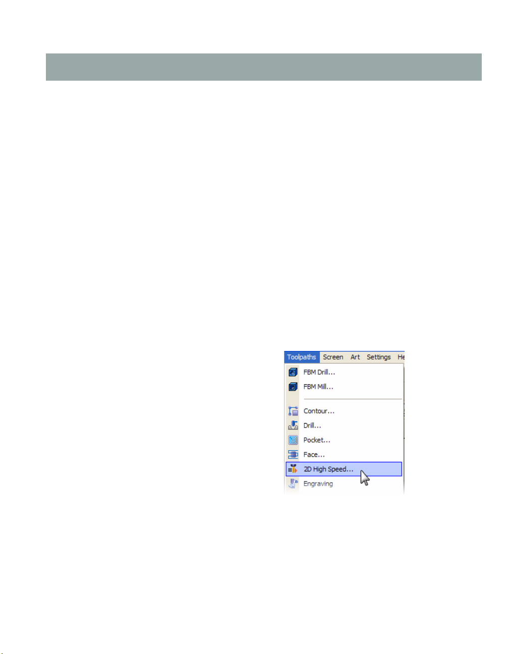
Mastercam offers a variety of toolpath types that let
you quickly build toolpaths for specific
applications. You access these toolpaths, such as
the mill toolpaths shown here, through the
Toolpa th s menu.
After you create a toolpath, you can use
Mastercam's backplot feature to preview its
operation on the screen. Once you are satisfied
with it, post it from the Toolpath Manager to
generate the NC code for a specific machine tool.
When you first begin this tutorial, you will be
prompted to assign a machine definition to the
part. This tutorial does not go into any depth on
machine and control definitions. However, the
Help and other documentation installed with
Mastercam provide comprehensive information
regarding these Mastercam features.
When you finish this tutorial, your part will look like this:
If you would like to design (create) the part before you begin this tutorial, please follow the Basic 2D
Design tutorial procedures (published separately in document #X5-PDF-TUT-2D).
Page 8

2 • BASIC 2D MACHINING
Tutorial Goals
Open a part file, assign a default machine definition, and set up stock.
Create four drill holes with one toolpath (including selecting a drill point, choosing tooling,
using tool tip compensation, and setting machining values).
Rough the outside of the part (including chaining entities, selecting tooling, and setting
machining values).
Clean out the inside of the part (including chaining entities, choosing tooling, and setting
machining values).
View all toolpaths in the graphics window.
View a specific toolpath by temporarily turning off the display of selected toolpaths.
Backplot (view the path the tools take to cut the part) all toolpaths.
Customize your backplot display.
Simulate (verify) the machining of the part from a stock model display.
Post all toolpath operations to an NC file, review/edit the code as necessary, and save the
NC file.
Before You Begin
This is a module of the Mastercam Getting Started Series Tutorial Series. The series introduces
general Mastercam functions and teaches basic skills for getting started with Mastercam. Other
tutorial series include:
Focus Series: Focuses on a specific Mastercam feature—for example, Setup Sheets or FBM
Drill, and teaches basic and advanced skills.
Exploring Series: Explores a single Mastercam product—for example, Mill, Solids, or Wire,
and teaches in-depth skills for working with the product.
The Mastercam tutorial series is in continual development, and we will add modules as we
complete them. For information and availability, please contact your local Mastercam Reseller.
IMPORTANT: Screen colors in the tutorial pictures were modified to enhance image
quality; they may not match your Mastercam settings or the tutorial results. These color
differences do not affect the lesson or the exercise results.
General Tutorial Requirements
All Mastercam tutorials have the following general requirements:
You must be comfortable using the Windows
The tutorials cannot be used with Mastercam Demo/Home Learning Edition (HLE). The
Demo/HLE file format (EMCX) is different from Mastercam (MCX), and basic Mastercam
functions, such as file conversions and posting, are unavailable.
®
operating system.
Page 9

INTRODUCTION • 3
Each lesson in the tutorial builds on the mastery of preceding lesson’s skills. We
recommend that you complete them in order.
Focus Series and Exploring Series tutorials require, at minimum, a mastery of the basic
Mastercam skills taught in the Getting Started Series modules. A general knowledge of
machining principals and practices is also required.
You must have a seat of Mastercam X5 Design or higher to complete most of the tutorials in
the Getting Started Series.
The Basic 2D Machining module in the Getting Started Series requires, at minimum, a seat
of Mill Entry or Router Entry.
The Basic 3D Machining module in the Getting Started Series requires Mill Level 3 or Router
Pro.
Additional files may accompany a tutorial. Unless the tutorial provides specific
instructions on where to place these files, store them in a folder that can be accessed from
the Mastercam workstation, either with the tutorial or in any location that you prefer.
The Getting Started Series tutorials are available in an Adobe
format. Additional tutorial videos may also be available. Contact your local Mastercam
Reseller for more information.
®
Flash® compatible video
You must install Adobe Flash Player to display tutorial videos. You can download Adobe
Flash Player from www.adobe.com.
You must configure Mastercam to work in metric units. Complete the instructions in the
following section Preparing for a Tutorial to set Mastercam to metric.
Preparing for a Tutorial
Before you start a tutorial, be sure you have completed the following tasks:
1 Start Mastercam using your preferred method:
Double-click Mastercam’s desktop icon.
Or
Launch Mastercam from the Windows Start menu.
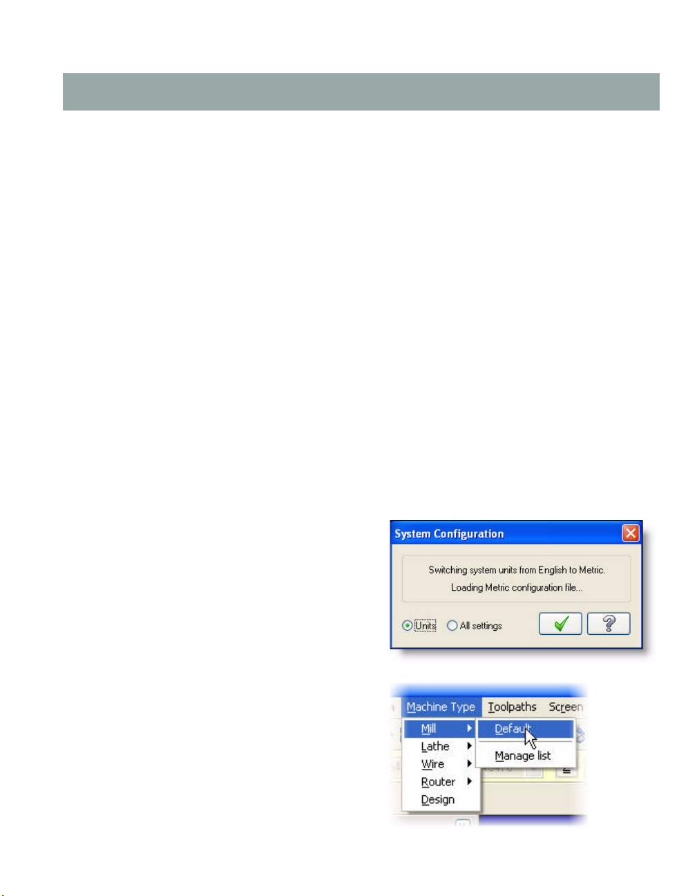
2 Select the metric configuration file:
a Select Settings, Configuration from
Mastercam’s menu.
b Choose ...\mcamxm.config <Metric>
from the Current drop-down list.
c Click OK.
If You Need More Help
There are many ways to get help with Mastercam, including the following:
Page 10

4 • BASIC 2D MACHINING
Mastercam Help—Access Mastercam Help by selecting Help, Contents from Mastercam’s
menu bar or by pressing [Alt+H] on your keyboard. Also, most dialog boxes and ribbon
bars feature a Help button that opens Mastercam Help directly to related information.
Online help—You can search for information or ask questions on the Mastercam Web
forum, located at www.emastercam.com. You can also find a wealth of information,
including many videos, at www.mastercam.com and www.mastercamedu.com.
Mastercam Reseller—Your local Mastercam Reseller can help with most questions about
Mastercam.
Technical Support—CNC Software’s Technical Support department (860-875-5006 or
support@mastercam.com) is open Monday through Friday from 8:00 a.m. to 5:30 p.m. USA
Eastern Standard Time.
Documentation feedback—For questions about this or other Mastercam documentation,
contact the Technical Documentation department by email at techdocs@mastercam.com.
Mastercam University—CNC Software sponsors Mastercam University, an affordable
online learning platform that gives you 24/7 access to Mastercam training materials. Take
advantage of more than 180 videos to master your skills at your own pace and help prepare
yourself for Mastercam Certification. For more information on Mastercam University,
please contact your Authorized Mastercam Reseller, visit www.mastercamu.com, or email
training@mastercam.com.
Additional Documentation
You can find more information on using Mastercam in the following materials, located in the
\Documentation folder of your Mastercam installation:
Mastercam X5 Installation Guide
Mastercam X5 Administrator Guide
Mastercam X5 Quick Start
Mastercam X5 Reference Guide
Mastercam X5 Transition Guide
Mastercam X5 Quick Reference Card
Mastercam X5 Wire Getting Started Guide
Version 9 to X Function Map
Mastercam X5 NCI & Parameter Reference
Mastercam X5 Post Debugger User’s Guide
Page 11
LESSON 1
1Drilling Holes
The first step to machining the tutorial part is to drill the four holes. By beginning with drilling, you
can then use the holes to fixture the part on the machine tool.
Lesson Goals
Open a part file and assign a machine definition.
Define stock.
Create a drill toolpath (including selecting drill points, choosing tooling, and setting
machining values).
Use tool tip compensation.
Exercise 1: Assigning a Machine Definition
In this exercise, you open an existing part, assign a machine definition to the part, and save it under
a new file name.
1 Start Mastercam.
2 From the Mastercam menu bar, choose File, Open.
3 Open BASIC_2D_MACHINING_START.MCX-5, which was provided with this tutorial.
4 Click OK if prompted to switch to a metric
configuration.
5 Press [Alt +S] to shade the part for easier
viewing.
6 From the Mastercam menu, choose
Machine Type, Mill, Default to open the
default Mill machine definition.
In Mastercam, you select a machine
definition before creating any toolpaths.
The machine definition is a model of your
machine tool's capabilities and features
and acts like a template for setting up
machining jobs.
Page 12

6 • BASIC 2D MACHINING
Note: Parts that have previously been saved with a machine definition automatically load the
associated machine definition.
7 Choose File, Save As and save the part under a different file name than the original file.
This will protect the original tutorial file from being overwritten.
Exercise 2: Setting Up Stock
In this exercise, you define the stock model from which your part is cut. Stock models help you
visualize your toolpaths more realistically. The stock model you define can be displayed with the
part geometry when viewing the file or toolpaths, during backplot, or while verifying toolpaths.
1 In the Operations Manager, click on the
plus sign (+) next to Properties - Mill
Default MM.
It changes to a minus sign (-) and displays
the machine group properties. Machine
groups are created automatically and
displayed in the Toolpaths Manager when
you select a machine from the Machine
Type menu. They include job setup
information for toolpaths, such as tool
numbering, stock models, material
selection, and toolpath defaults and
libraries.
2 Click the Stock Setup icon to display the
Stock Setup tab in the Machine Group
Properties dialog box.
Page 13

DRILLING HOLES • 7
3 Click the Select corners button near the bottom of the dialog box. Mastercam brings you
back to the graphics window to select the two opposite stock corners.
4 Click the two opposite corners as shown in the following picture. The Stock Setup tab
displays again with X and Y coordinate values from the selected corners.
5 Enter 25 for the Z coordinate in the stock diagram to provide some depth for your stock.
6 Select the Display check box to see the stock model boundaries in the graphics window.
Page 14
8 • BASIC 2D MACHINING
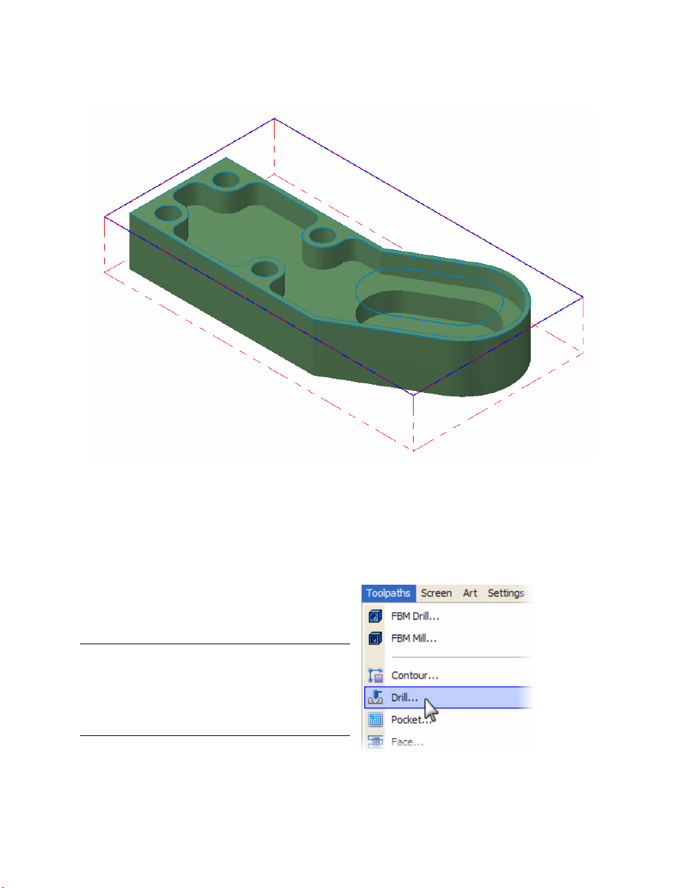
7 Click OK to complete the stock setup. The stock displays as dashed red lines around the
part.
Exercise 3: Drilling Four Holes
In this exercise, you create a drill toolpath that drills all four holes of the part.
Selecting the Drill Holes
1 From the Mastercam menu, choose
Toolpaths, Drill. The Drill Point Selection
dialog box opens.
Note: You may be prompted for an NC file
name. If prompted, click OK to confirm the
default NC file name, or overwrite the file
name and click OK to modify the default file
name.
Page 15
DRILLING HOLES • 9
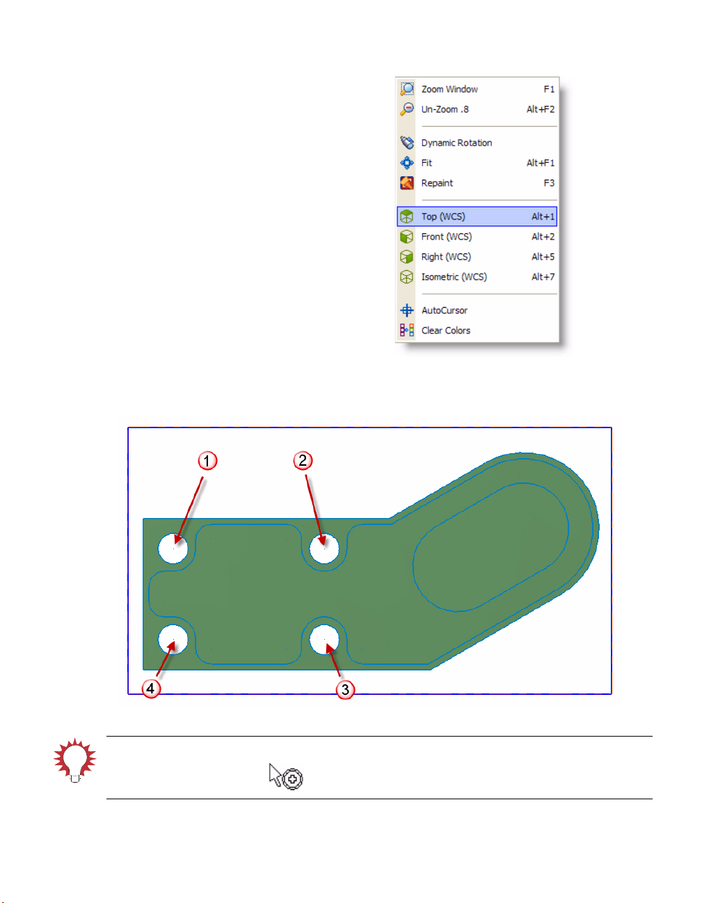
2 Right-click in the graphics window and
choose To p ( W C S ) to switch to a Top
graphics view. This will make it easier to
select the drill holes.
3 Click each of the center points of the four holes of the part. Choose them in a clockwise
order from top left to bottom left as shown in the numbered sequence below.
TIP: When you get close to each hole’s center point, Mastercam displays a Visual Cue that
indicates the center point.
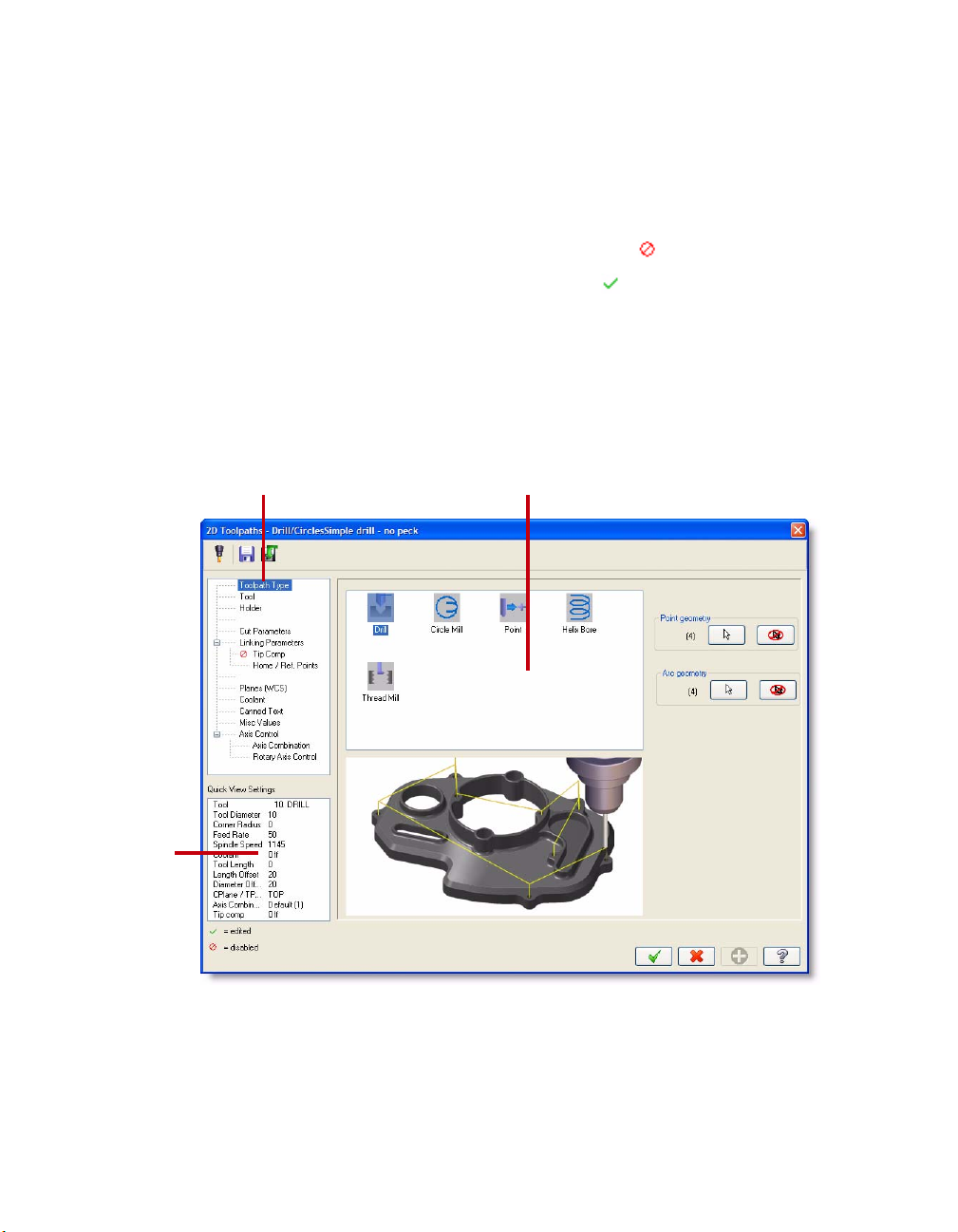
4 Click OK. The 2D Toolpaths - Drill/Circles dialog box opens.
Page 16
10 • BASIC 2D MACHINING
Page viewTree view area
Quick
View
Settings
area
Exploring the Toolpath Dialog Boxes
Many Mastercam toolpaths, including Drill, use a tree-style dialog interface made up of
three distinct areas:
Tree View - Displays a list of all the available dialog box property pages.
Inactive pages are marked with a red circle and a slash.
Edited pages are marked with a green check mark.
Some pages may have a plus or minus symbol, indicating that the page has subpages
and can expand and contract to either display or hide the subpages.
Page View - Changes with each selection you make in the Tree View area.
Quick View Settings - Summarizes key toolpath information from parameters you set on
the different pages. It updates automatically as you make changes in the pages, and is
always visible.
Page 17
DRILLING HOLES • 11
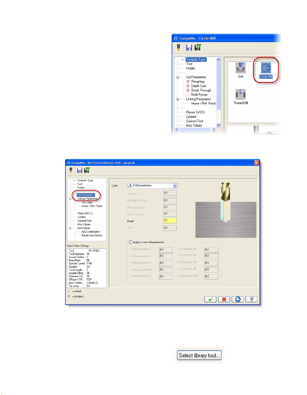
1 Click on the Circle Mill toolpath type icon.
This changes the toolpath to a circle mill
toolpath and changes the pages listed in
the Tree View area.
Notice that the Toolpath Type page in the
Tree View area now has a green check
beside it, indicating that you made a
change on that page.
2 Click the Drill toolpath type icon to change
back to a drill toolpath.
3 Click the Cut Parameters page in the Tree View list. The Page area changes to list cut
parameters for the toolpath.
Setting Drilling Parameters
1 Click the To o l page in the Tree View list to pick a tool for the drill toolpath.
2 Click the Select library tool button to pick
a tool from one of Mastercam’s tool
libraries.
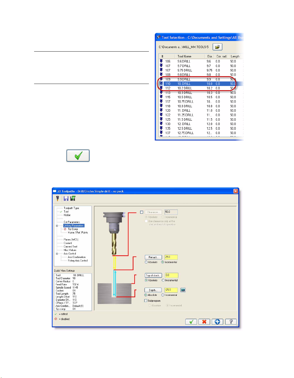
The Tool Selection dialog box opens.
Page 18
12 • BASIC 2D MACHINING
3 Select the 10mm diameter drill from the
tool list.
Note: Make sure that the Mill_MM.TOOLS
tool library is selected at the top of the dialog
box. If not, click the drop-down arrow and
select it from the tool library list.
4 Click OK to return to the Tool page.
5 Click the Linking Parameters page in the Tree View list.
6 Enter -25.0 in the Depth field.
7 Click the Tip Comp page in the Tree View list. Notice that this page is off by default.
Page 19

DRILLING HOLES • 13
8 Select the Tip Comp check box to turn on this feature and enter 5.0 in the Breakthrough
amount field.
TIP: The drill tip compensation tells Mastercam how far to drill past the final depth to break
through the stock. Enter a positive number only. Entering a negative value results in the drill
retracting before the desired depth is reached.
9 Click OK to generate the drill toolpath for the four holes.
10 Right-click in the graphics window and
choose Isometric (WCS) from the menu to
view the part and toolpath in the isometric
view.
You may need to center the part in the
graphics window to see it. The easiest way
to do this is to use the graphics window
right-click menu and select Fit to fit the
part in the graphics window, then unzoom
by pressing [Alt+F2]. You can also use the
fit/zoom/unzoom buttons in the View
Manipulation toolbar.
Page 20
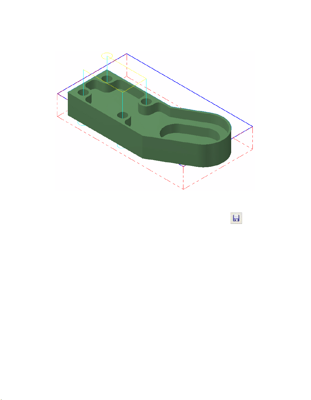
14 • BASIC 2D MACHINING
Your toolpath should look like this. The cyan lines are feed motion and the yellow lines are
rapid motion.
11 Right-click in the graphics window again, and choose Top (W C S ) .
12 Choose File, Save from the Mastercam menu or click the Save button to save your
part.
Now that the holes are drilled, you can move forward with removing stock from the outer area of
the part.
Page 21

LESSON 2
2Roughing Outside the Part
The next step to machining the tutorial part is to remove the bulk of the stock from the outside. You
will use a couple of toolpaths to machine this area.
Lesson Goals
Create a dynamic mill toolpath (including chaining entities, choosing tooling, and setting
machining values).
View a specific toolpath by temporarily turning off the display of selected toolpaths.
Create a contour toolpath (including chaining entities, choosing tooling, and setting
machining values).
Exercise 1: Creating a Dynamic Mill Toolpath
In this exercise, you create a dynamic mill 2D toolpath to clear away much of the stock from the
outside of the tutorial part. Dynamic mill toolpaths, part of the 2D High Speed toolpath suite, utilize
the entire flute length of their cutting tools to produce the smoothest, most efficient tool motion for
high speed pocketing and core milling.
1 From the Mastercam menu, choose
Toolpaths, 2D High Speed. The Chaining
dialog box opens.
Chaining is the process of selecting one or
more entities and linking them together in
a specific order and direction. The entities
must have adjoining endpoints and may
be open or closed shapes.
2 Press [Alt+S] to turn off shading and make it easier to select the chains.
Page 22
16 • BASIC 2D MACHINING
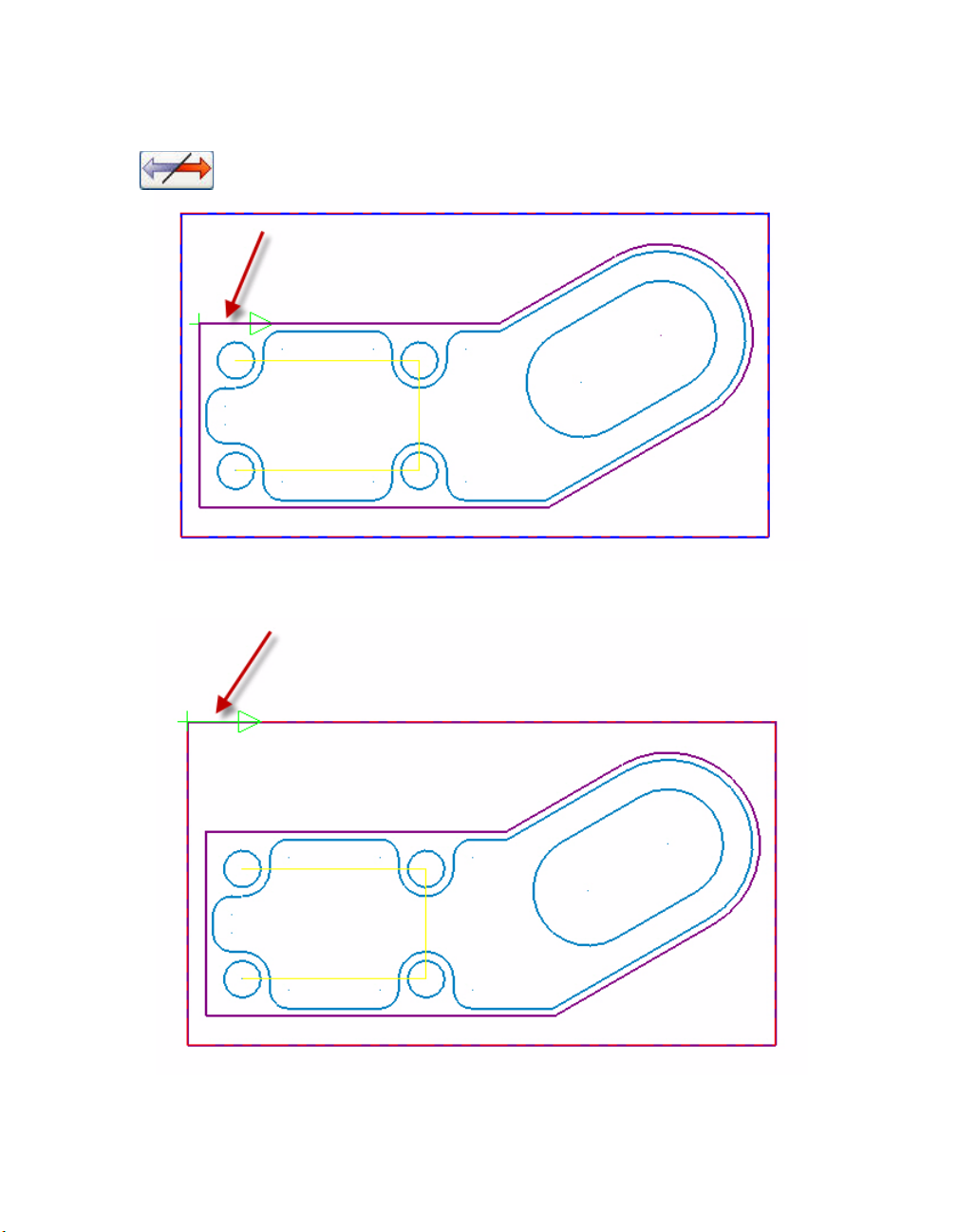
3 Click the outside contour of the part to chain it. The chaining arrow should point
clockwise. If the chaining direction arrow is pointing counterclockwise, click the Reverse
button on the Chaining dialog box.
4 Click the top of the stock boundary as the second chain. This second chain represents the
size of the stock material. The chaining arrow should again point clockwise.
5 Click OK on the Chaining dialog box to chain the part. The Chaining dialog box closes and
the 2D High Speed Toolpath dialog box opens.
Page 23

ROUGHING OUTSIDE THE PART • 17
6 Select the Dynamic Core Mill toolpath type. The Tree View area updates with a list of
parameters for dynamic mill toolpaths.
7 Click the To o l page in the Tree View list to select a tool for this toolpath.
8 Click the Select library tool button. The
default metric tool library opens.
9 Select the 12mm diameter flat endmill, and click OK.
Page 24
18 • BASIC 2D MACHINING
Setting the Dynamic Mill Toolpath Parameters
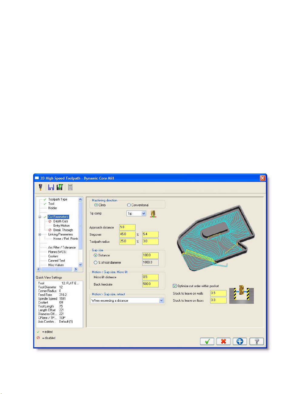
1 Click the Cut Parameters page in the Tree View area to enter values for different cutting
parameters and compensation options.
2 Set the following parameters:.
Enter 5.0 for the Approach distance, which adds the specified absolute distance to
the beginning of the toolpath’s first cut.
Enter 25% for the Toolpath radius. This parameter is used to calculate 3D arc moves
and reduce sharp corner motion between passes.
Enter 0.5 for the Micro lift distance. Microlifts are slight lifts during back moves that
help clear chips and minimize excessive tool heating.
Select When exceeding a distance from the Retract drop-down list, select the
Distance radio button in the Gap size group box, and enter 100.0. Mastercam adds
retract motion when the next cut begins at a distance greater than the distance you
define.
Enter 0.5 for the Stock to leave on walls.This leaves 0.5mm of stock on the outer
walls.
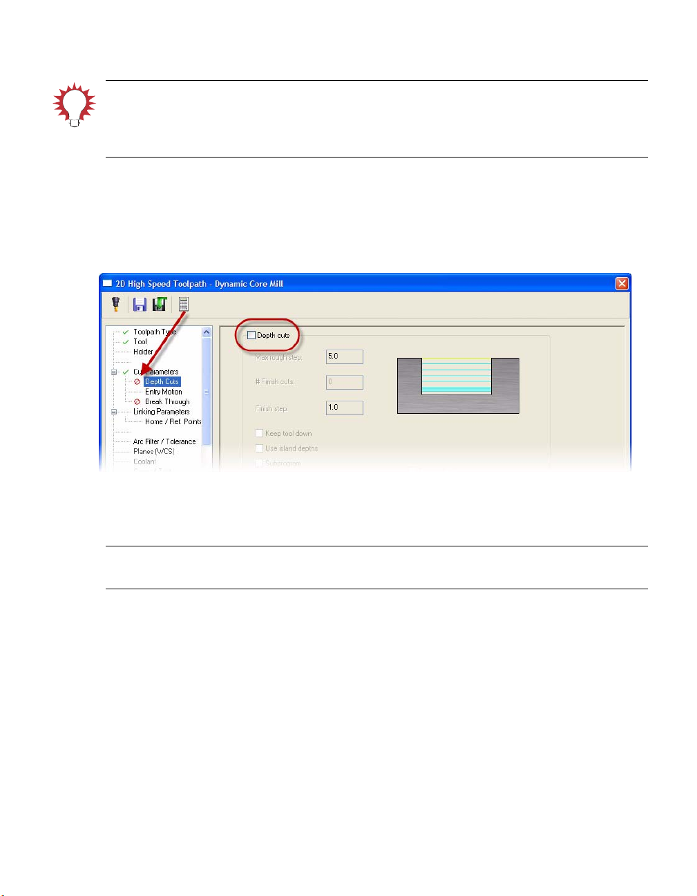
3 Click the Depth cuts page in the Tree View area.
Page 25
ROUGHING OUTSIDE THE PART • 19
TIP: Depth cuts divide the total depth of a toolpath into smaller Z-axis cuts to reduce tool
wear. You can enter a maximum rough step, and Mastercam divides the total depth into
equal steps. Or you can enter the exact number of finish steps and the size of each finish
step. For more details, please refer to the Mastercam Help.
4 Deselect the Depth cuts check box to turn off depth cuts for this toolpath. Notice the red
circle and a slash that displays next to the Depth Cuts page, indicating that the options on
this page are all turned off.
Dynamic mill toolpaths utilize the full flute length of your tool, so dividing the toolpath
into smaller cuts is not necessary.
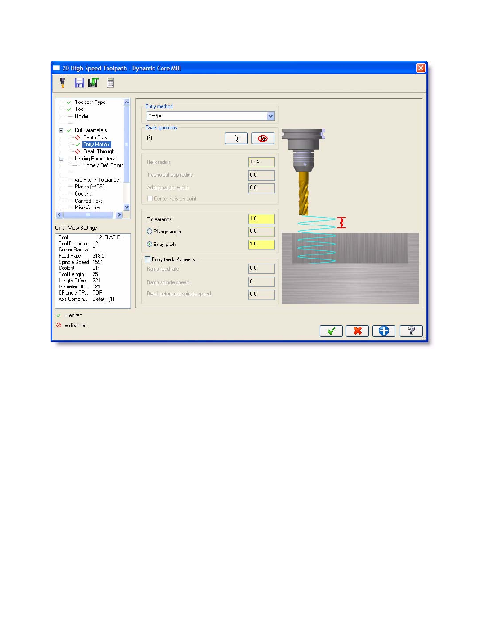
5 Click the Entry Motion page in the Tree View list to set how and where the tool enters the
stock.
Note: The open pocket machining method enters from outside the material - these entry
parameters are only used if Mastercam encounters a closed pocket.
6 Set the following parameters:
Select Profile from the Entry method drop-down list. This entry method creates a
ramp entry based on the shape of the offset pocket. The slot is cleared by taking
lighter cuts in the Z axis. Subsequent cuts are properly engaged at the full cut depth.
Enter 1.0 for the Z clearance. This is an extra height used in the ramping motion
down from a top profile. It ensures that the tool has fully slowed down from rapid
speeds before touching the material, so that it enters the material smoothly at the
plunge angle.
Select the Entry pitch radio button and enter 1.0 for the distance. This controls the
entry descent by the pitch value you define. Mastercam lowers the tool by the pitch
value for every complete revolution of the entry motion, ensuring the tool is never
buried by more than the specified pitch.
Page 26
20 • BASIC 2D MACHINING
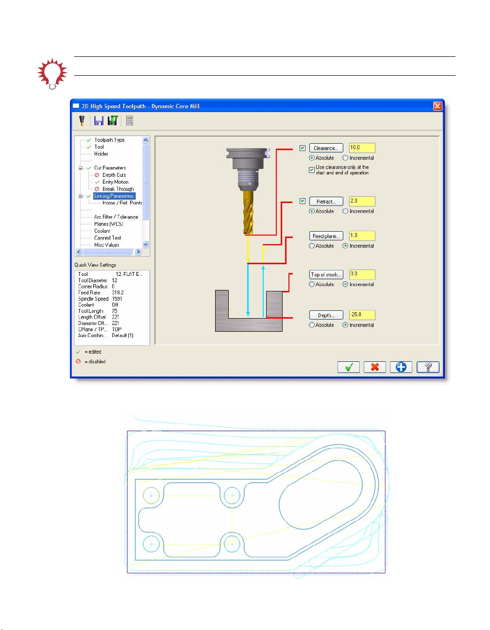
7 Click the Linking Parameters page in the Tree View list to set important heights such as
clearance, retract, and feed plane, as well as the final toolpath depth.
8 Set the following parameters:
Select the Clearance check box and enter 10.0 for the height, which is the height at
which the tool moves to and from the part.
Select the Use clearance only at the start and end of operation check box, so the
toolpath rapids to the clearance height only at the start and end of the toolpath.
Enter 2.0 for the Retract height and select the Absolute radio button. This is the
height that the tool moves up to before the next tool pass. By selecting Absolute, the
retract height is always measured from 0,0,0, not relative to any selected geometry.
Enter 1.0 for the Feed plane height, which is the height that the tool rapids to before
changing to the plunge rate to enter the part.
Enter 0 for the Top of stock height, which is the height of the material in the Z axis.
Enter -25.0 for the Depth. This value determines the final machining depth and the
lowest depth that the tool descends into the stock. In this case, the depth is -25mm,
or 25 mm below the top of the part.
Page 27
TIP: The default depth is the depth of the selected geometry.
ROUGHING OUTSIDE THE PART • 21
9 Click OK to generate the toolpath.
Page 28
22 • BASIC 2D MACHINING
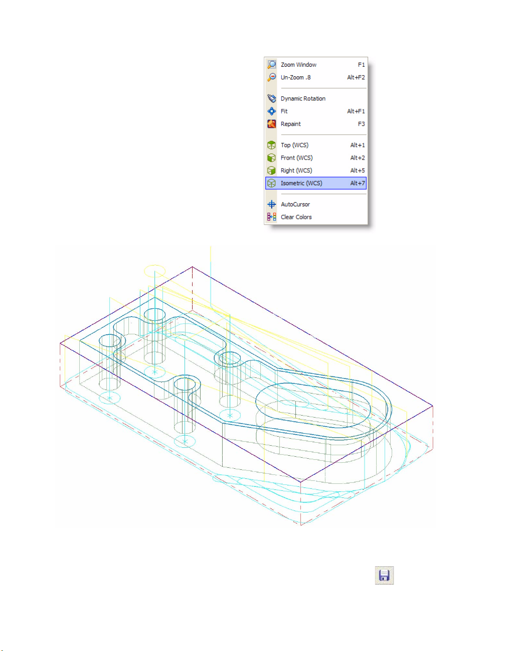
10 Right-click in the graphics window and
choose Isometric (WCS) from the menu to
view the part and toolpath in the isometric
view.
The toolpath cleans most of the material
outside the part using smooth, efficient
tool motion.
11 Right-click in the graphics window again and choose Top (W C S ) from the menu to view the
part and toolpath in the top view.
12 Choose File, Save from the Mastercam menu or click the Save button to save your
part.
Page 29
ROUGHING OUTSIDE THE PART • 23
Exercise 2: Viewing Your Toolpaths
In this exercise, you will temporarily turn off the display for the drill and dynamic mill toolpaths so
that you easily see any additional toolpaths you create.
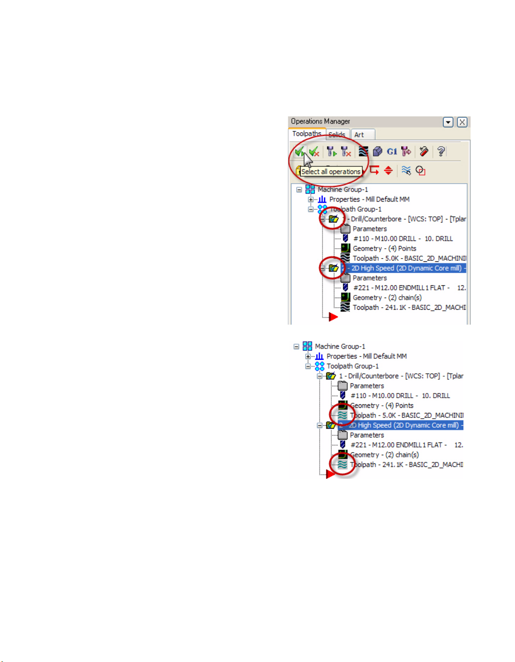
1 In the Toolpath Manager, click the Select
all operations button. Check marks
display on the yellow folders of each
toolpath, which indicates that they are
selected.
2 Press [T] to toggle off the toolpath display
of both toolpaths in the graphics window.
This function toggles the visibility of
toolpaths on and off in the graphics
window so that you can view only specific
toolpaths.
The Toolpath icon changes to gray when
the toolpath display is toggled off.
Exercise 3: Creating a Contour Toolpath
To get the final finish on the outer walls with no stock remaining, you will create a contour toolpath.
Contour toolpaths remove material along a path defined by a chain of curves. Contour toolpaths
only follow a chain; they do not clean out an enclosed area.
Page 30
24 • BASIC 2D MACHINING
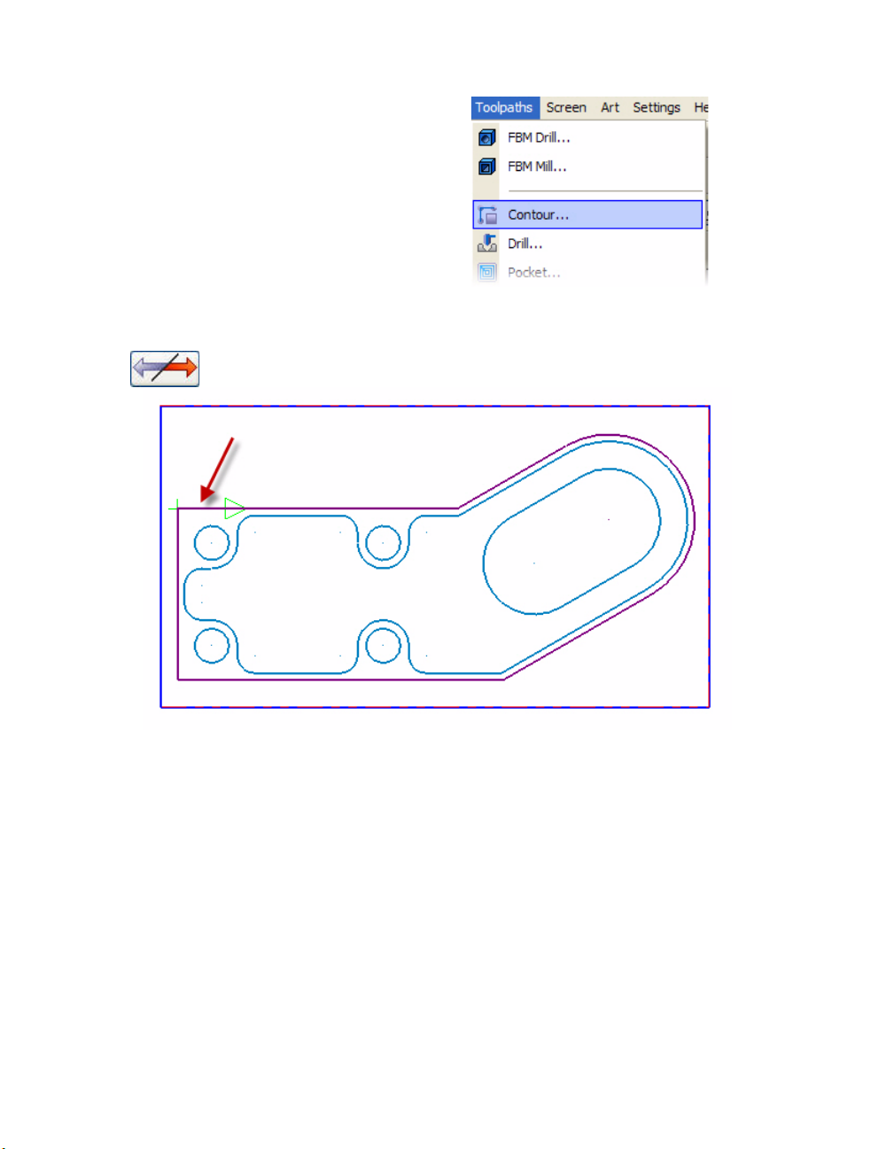
1 From the Mastercam menu, choose
Toolpaths, Contour. The Chaining dialog
box opens.
2 Click the outside contour of the part to chain it. The chaining arrow should point
clockwise. If the chaining direction arrow is pointing counterclockwise, click the Reverse
button on the Chaining dialog box.
3 Click OK on the Chaining dialog box to chain the part. The Chaining dialog box closes and
the 2D Toolpaths - Contour dialog box opens.
4 Click the To o l page in the Tree View list to select a tool for this toolpath.
Page 31
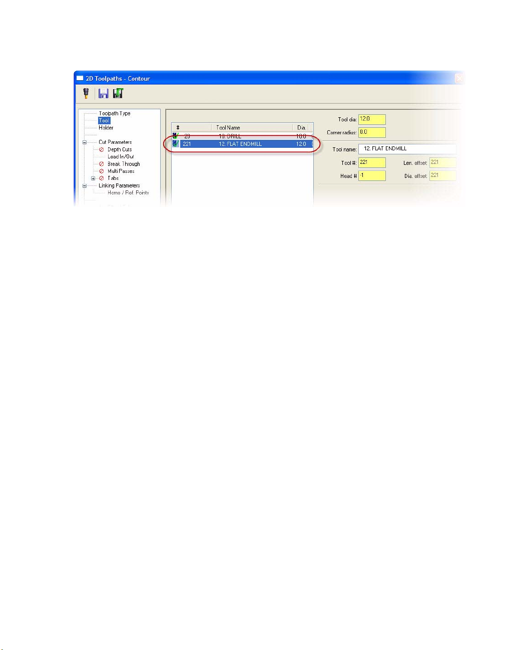
ROUGHING OUTSIDE THE PART • 25
5 Select the 12mm diameter flat endmill you used for the dynamic mill toolpath.
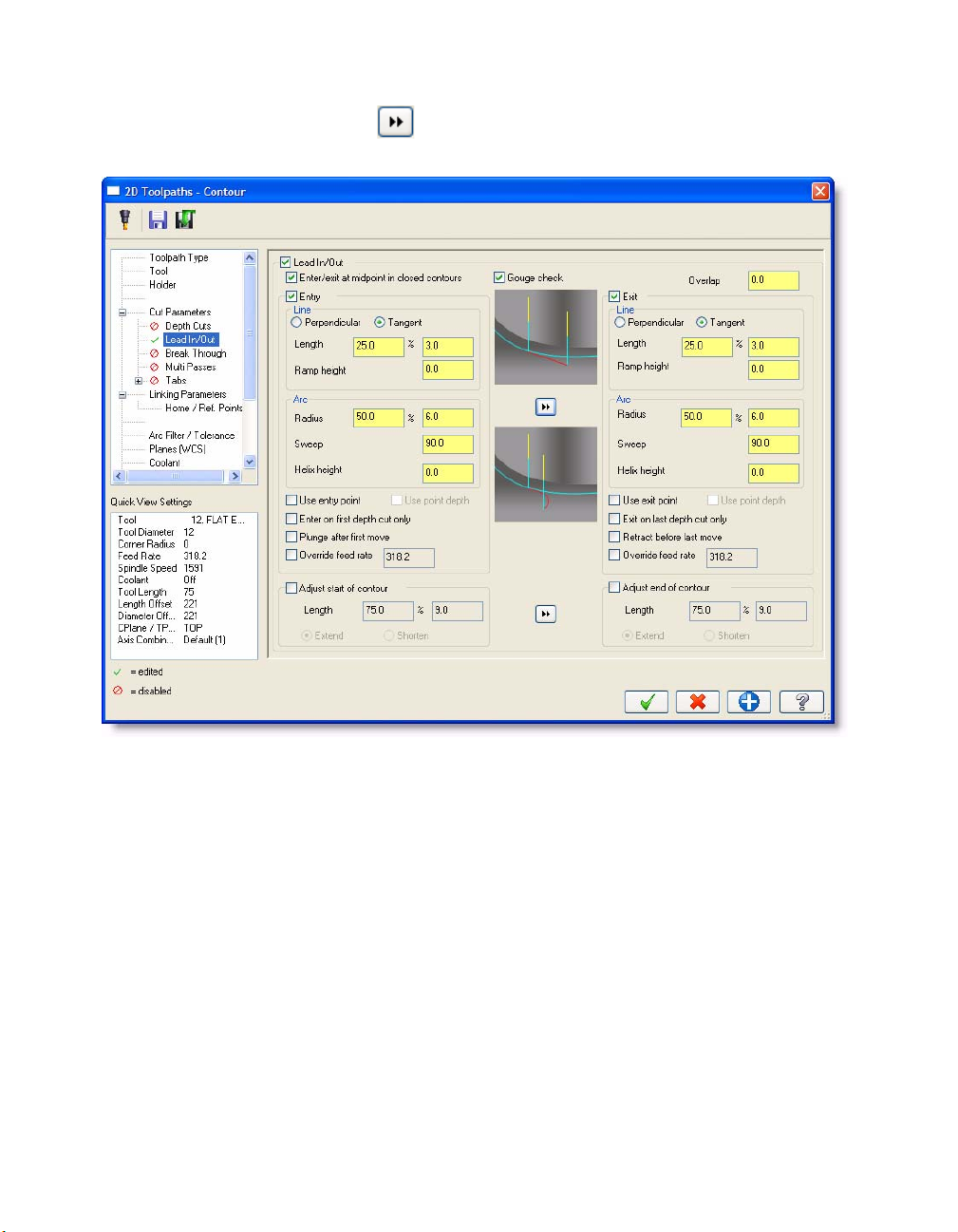
Setting the Contour Toolpath Parameters
1 Click the Lead In/Out page in the Tree View area to enter values for the entry and exit
moves.
Lead in/out or entry/exit moves are a combination of lines and arcs at the beginning and
end of a 2D or 3D contour toolpath. They control how the tool approaches and pulls away
from the toolpath.
Mastercam places entry and exit lines relative to the entry and exit arcs. If both an entry
line and entry arc are defined, the line is machined first. If both an exit line and exit arc are
defined, the arc is machined first. The lead in/out entry points may differ based on where
you clicked the geometry to chain it.
2 Set the following parameters:
Enter 25% for the Entry Line Length.
Enter 50% for the Entry Arc Radius.
Page 32
26 • BASIC 2D MACHINING
Click the arrow button in the center of the page to copy the values to the Exit
parameters.
3 Click the Linking Parameters page in the Tree View list.
4 Set the following parameters:
Select the Clearance check box and enter 10.0 for the height.
Select the Use clearance only at the start and end of operation check box.
Enter 2.0 for the Retract height and select the Absolute radio button.
Enter 1.0 for the Feed plane height.
Enter 0 for the Top of stock height.
Enter -25.0 for the Depth.
Page 33

ROUGHING OUTSIDE THE PART • 27
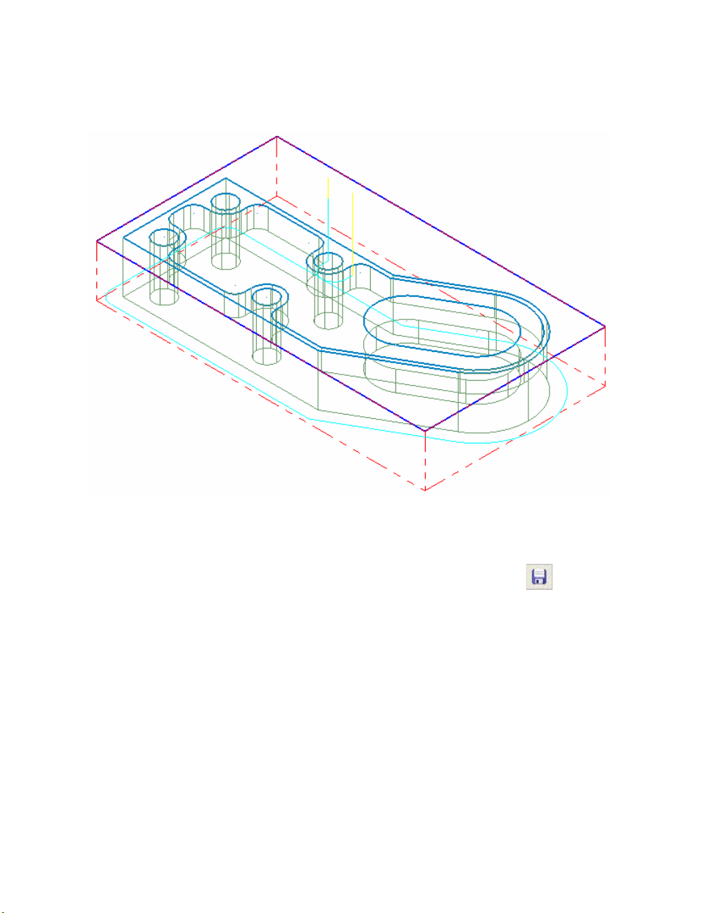
5 Click OK to generate the toolpath.
Page 34
28 • BASIC 2D MACHINING
6 Right-click in the graphics window and choose Isometric (WCS) from the menu to view the
part and toolpath in the isometric view. The contour toolpath removes the 0.5mm left
behind by the dynamic mill toolpath and machines the outer wall to its final size.
7 Right-click in the graphics window again and choose Top (WCS) from the menu to view the
part and toolpath in the top view.
8 Choose File, Save from the Mastercam menu or click the Save button to save your
part.
The stock has been removed from the outer areas of the part. In the next lesson, you will remove
material from the inner areas of the part, including the slot.
Page 35
LESSON 3
3Machining Inside the Part
The next step in machining the tutorial part is to clean out material from the inside. You will use
two toolpaths specifically geared towards the areas inside the part.
Lesson Goals
Create a dynamic mill toolpath (including chaining entities, choosing tooling, and setting
machining values).
Create a slot mill toolpath (including chaining entities, choosing tooling, and setting
machining values).
Exercise 1: Creating a Dynamic Mill Toolpath
In this exercise, you create a dynamic mill toolpath to clean out the large interior shape of the
tutorial part. This toolpath type works well for all pocket shapes because the tool goes right to the
final depth, and you can cut using the whole flute length instead of stepping down.
1 Select the Contour toolpath in the Toolpath Manager and press [T] to turn off the toolpath
display. This makes it easier to see the new toolpaths you create.
2 From the Mastercam menu, choose
Toolpaths, 2D High Speed. The Chaining
dialog box opens.
Page 36

30 • BASIC 2D MACHINING
3 Click the inner contour of the part to chain it.
4 Click OK on the Chaining dialog box to chain the part. The Chaining dialog box closes and
the 2D High Speed Toolpath dialog box opens.
5 Select the Dynamic Area Mill toolpath type. The Tree View area updates with a list of
parameters for dynamic mill toolpaths.
6 Click the To o l page in the Tree View list to select a tool for this toolpath.
Page 37
7 Click the Select library tool button. The
default metric tool library opens.
8 Select the 6mm diameter flat endmill, and click OK.
Setting the Dynamic Mill Toolpath Parameters
MACHINING INSIDE THE PART • 31
1 Click the Cut Parameters page in the Tree View area to enter values for different cutting
parameters and compensation options.
TIP: Notice that the parameter values are the same as the last dynamic mill toolpath you
created. Many of the Mastercam dialog boxes retain their previous settings, saving you from
having to reenter data, reselect function buttons, or reselect options in a drop-down list. The
settings stay in their “last used” state for the remainder of the Mastercam session or until
you change them.
2 Set the following parameters:
Enter 35% for the Stepover.
Select Never from the Retract drop-down list.
Enter 0 (zero) for the Stock to leave on walls.
Page 38

32 • BASIC 2D MACHINING
Note: See Setting the Dynamic Mill Toolpath Parameters on page 18 for more information on
these parameters.
3 Click the Linking Parameters page in the Tree View list to set important heights such as
clearance, retract, and feed plane, as well as the final toolpath depth.
Page 39

4 Enter -10.0 for the Depth.
MACHINING INSIDE THE PART • 33
5 Click OK to generate the toolpath.
Page 40

34 • BASIC 2D MACHINING
6 Right-click in the graphics window and choose Isometric (WCS) to view the part and
toolpath in the isometric view. The toolpath cleans off the floor of the part, but doesn’t
completely machine the additional slot.
7 Right-click in the graphics window again and choose Top (WCS) from the menu to view the
part and toolpath in the top view.
8 Choose File, Save from the Mastercam menu or click the Save button to save your
part.
Exercise 2: Creating a Slot Mill Toolpath
Slot mill toolpaths are designed to efficiently machine obround slots. These are slots that consist of
2 straight lines and two 180-degree arcs at the ends, such as the remaining slot on your part.
1 Select the second Dynamic Mill toolpath in the Toolpath Manager and press [T] to turn off
the toolpath display. This makes it easier to see the new toolpaths you create.
2 From the Mastercam menu, choose Toolpaths, Circle Paths, Slot Mill. The Chaining dialog
box opens.
Page 41
MACHINING INSIDE THE PART • 35
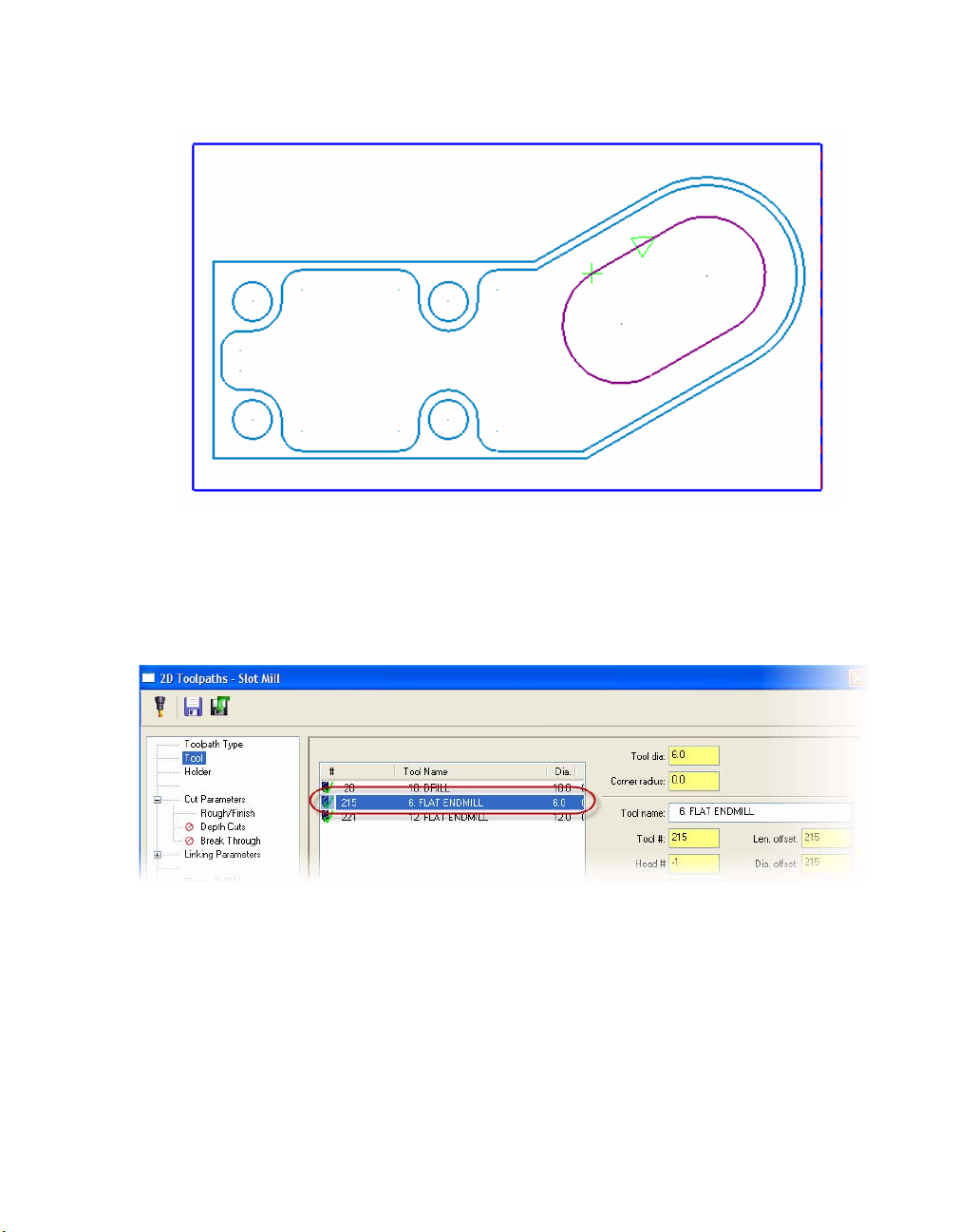
3 Click the slot to chain it. The chaining arrow should point clockwise.
4 Click OK on the Chaining dialog box to chain the part. The Chaining dialog box closes and
the 2D Toolpaths - Slot Mill dialog box opens.
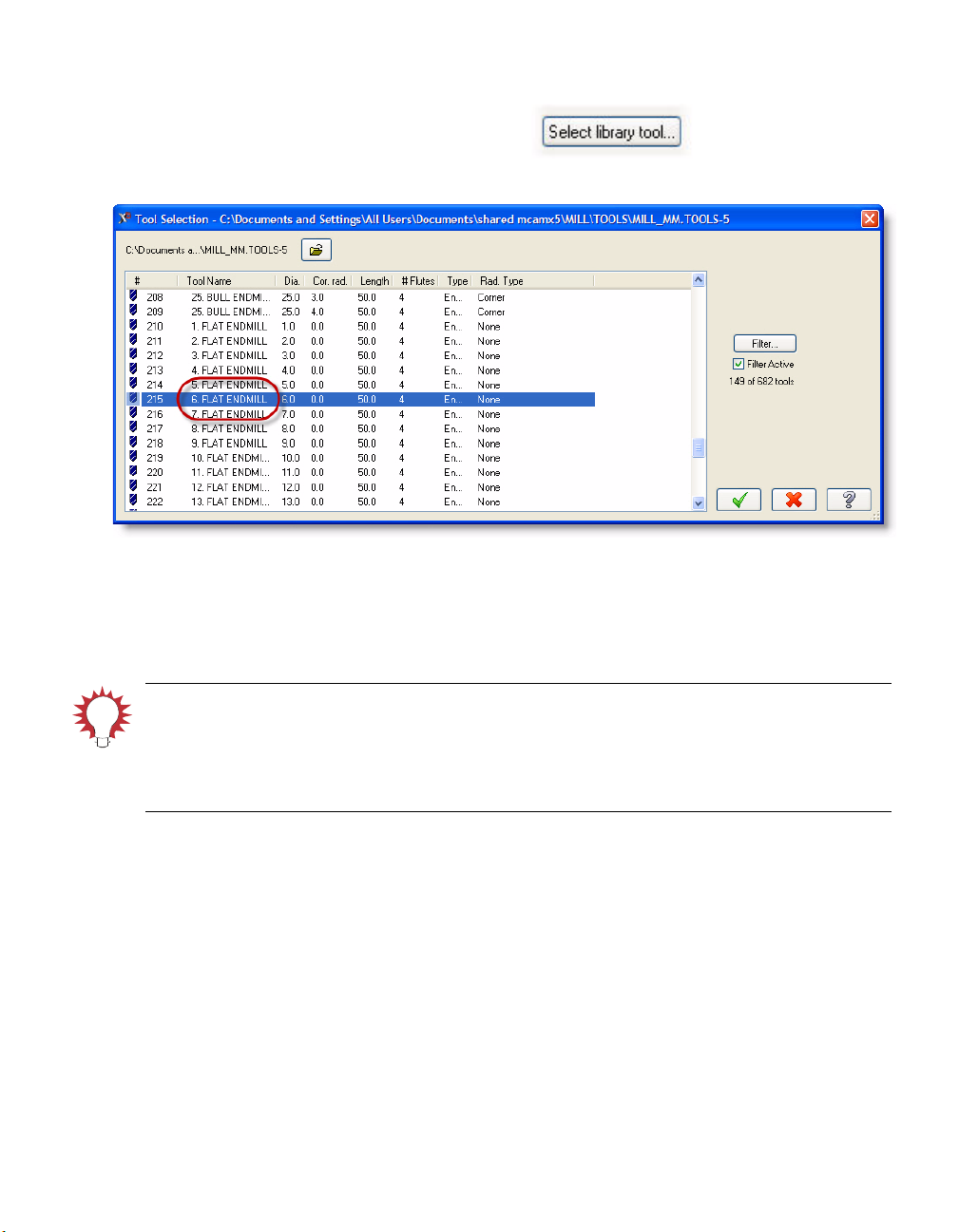
5 Click the To o l page in the Tree View list to select a tool for this toolpath.
6 Select the 6mm diameter flat endmill you used for the dynamic mill toolpath.
Setting the Slot Mill Toolpath Parameters
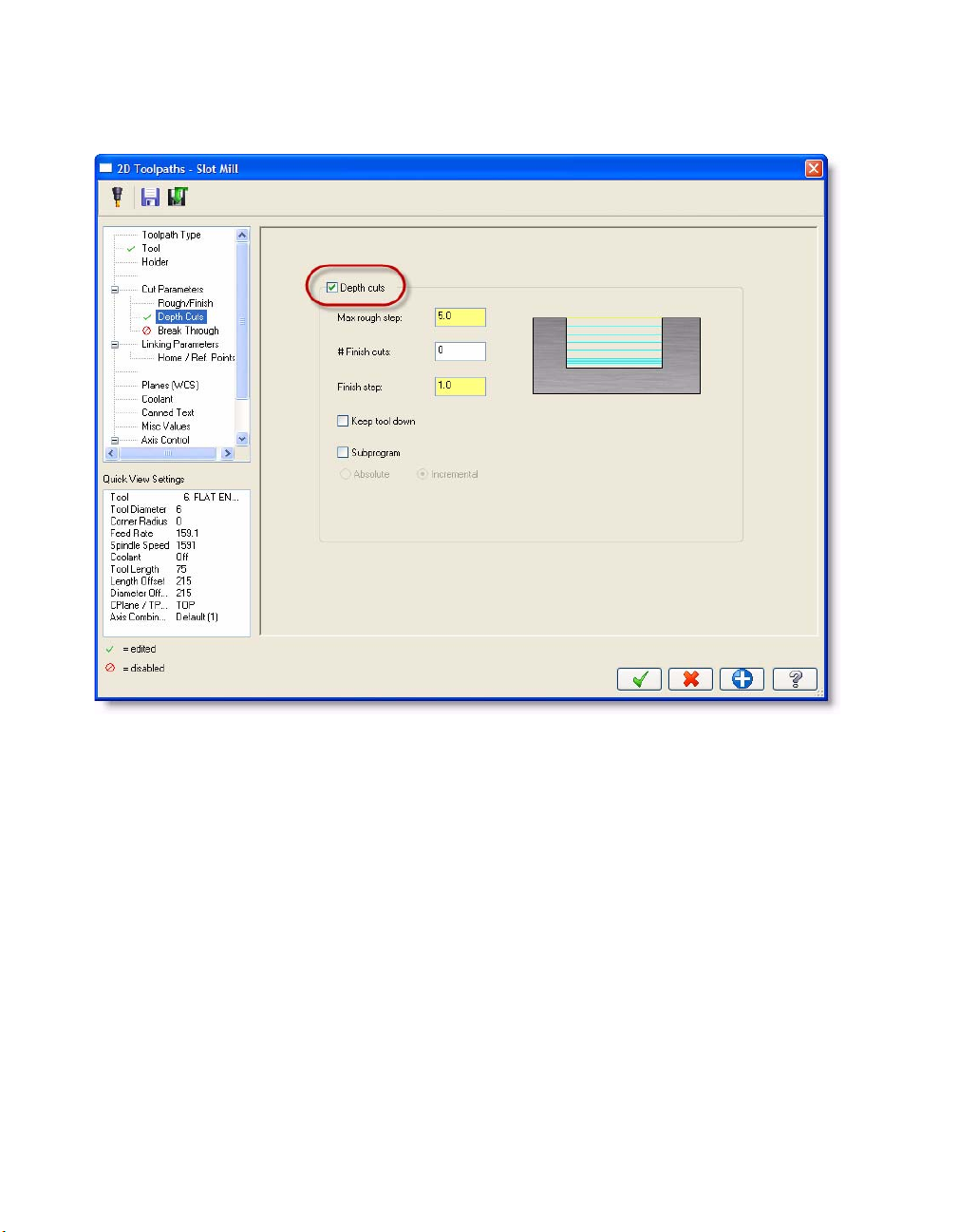
1 Click the Depth Cuts page in the Tree View area to enter values for different cutting
parameters and compensation options.
Page 42
36 • BASIC 2D MACHINING
2 Select the Depth cuts check box to turn on depth cuts. The default parameter values are
used for this toolpath.
3 Click the Linking Parameters page in the Tree View list.
Page 43
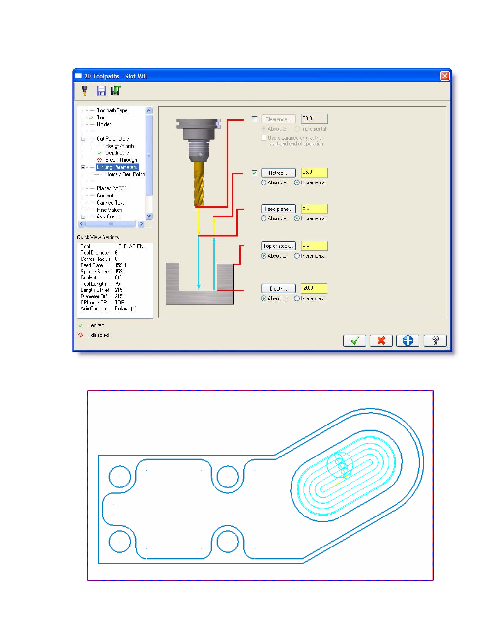
4 Enter -20.0 for the Depth.
MACHINING INSIDE THE PART • 37
5 Click OK to generate the toolpath.
Page 44
38 • BASIC 2D MACHINING
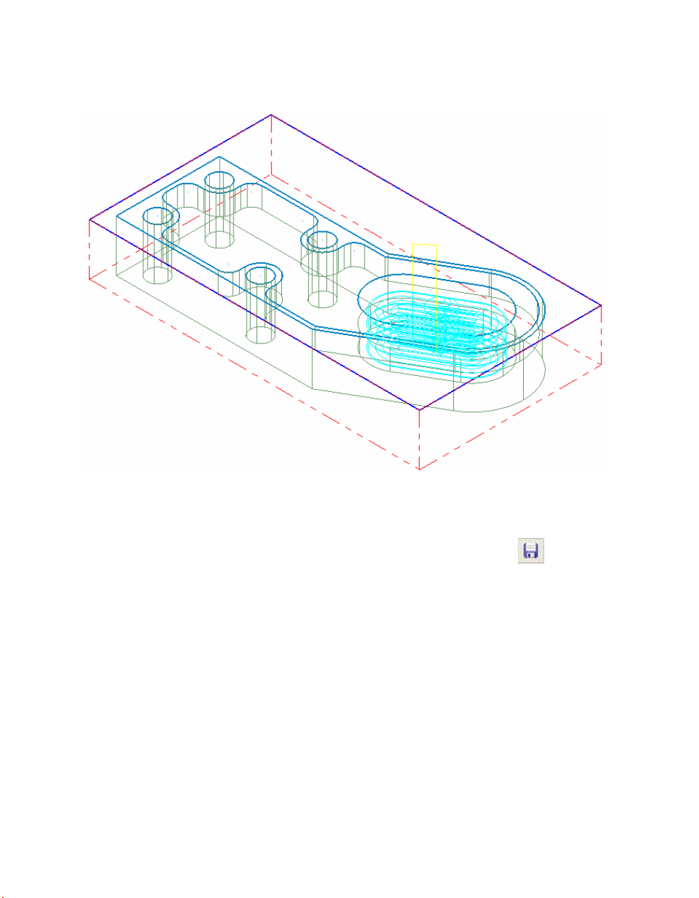
6 Right-click in the graphics window and choose Isometric (WCS) to view the part and
toolpath in the isometric view. The slot is machined in four depth cuts.
7 Right-click in the graphics window again and choose Top (WCS) from the menu to view the
part and toolpath in the top view.
8 Choose File, Save from the Mastercam menu or click the Save button to save your
part.
Now that you have machined all areas of the part, you can use Mastercam’s Backplot and Verify
functions to check your toolpaths before sending them to the machine tool.
Page 45
LESSON 4
4Previewing Toolpaths
Mastercam has several ways of viewing your toolpath motion before you actually machine your
part. Visualizing the machining process for this part is an important step before sending the
program to your machine control.
Lesson Goals
Backplot all toolpaths.
Customize your backplot display.
Verify all toolpaths.
Exercise 1: Backplotting All Toolpaths
Backplot is a Mastercam function that allows you to see the path the tools take to cut the part. This
display lets you spot errors in the program before you machine the part.
Note: This lesson assumes that you have successfully completed Lessons 1 through 3 of the Basic
2D Machining tutorial and have saved the MCX file. If you have not, or if you think your
completed part file is incorrect, open the BASIC_2D_MACHINING_FINISH.MCX-5 file provided
with this tutorial.
1 If necessary, open Mastercam and your part (see note above).
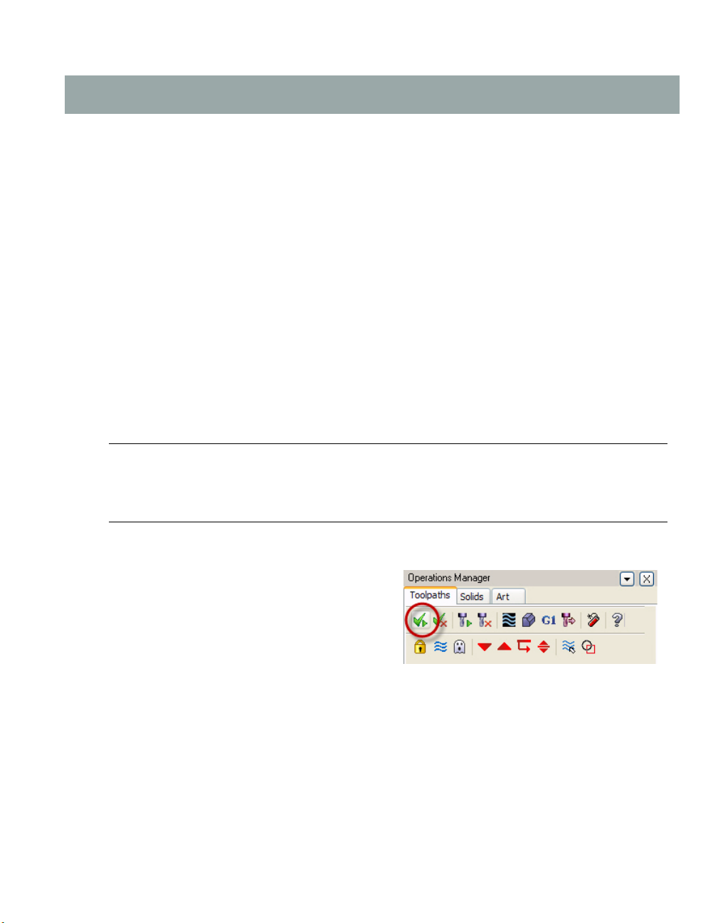
2 At the top of the Toolpath Manager, click
the Select all operations button.
Page 46
40 • BASIC 2D MACHINING
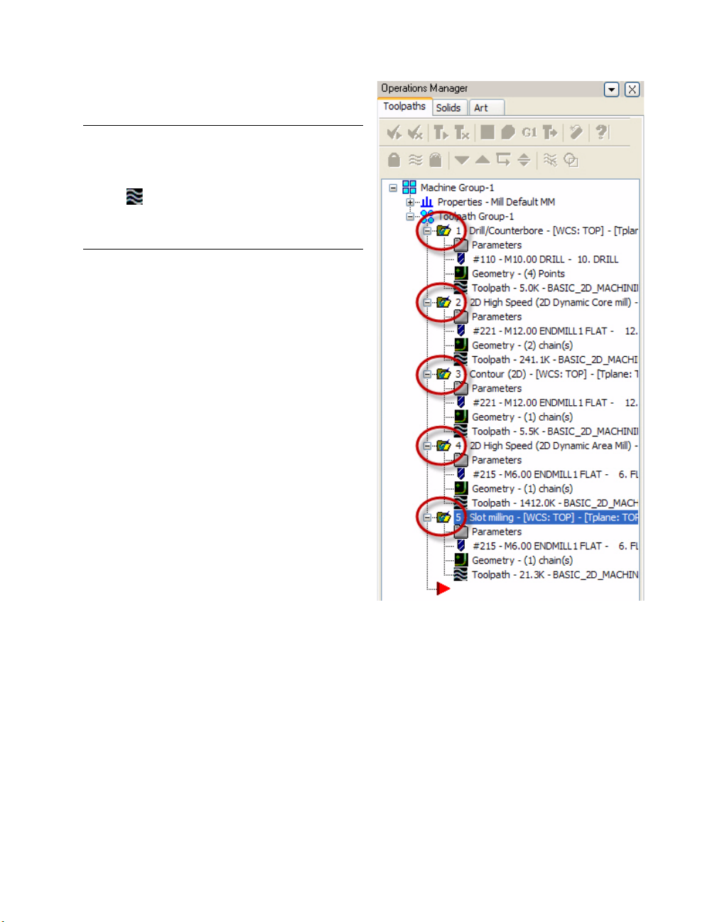
All five toolpath folders display a check
mark.
Note: Make sure that all toolpaths are set to
display in the graphics window.
The Toolpath icon for each toolpath should be
black.
If any of the toolpaths are not displayed, press
[T].
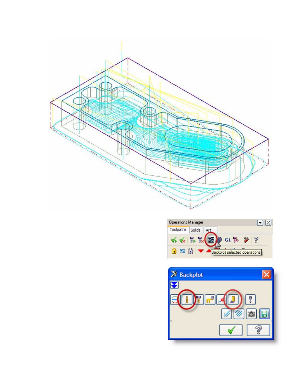
3 Right-click in the graphics window and choose Isometric (WCS) from the menu to view the
part and all toolpaths in the isometric view.
Page 47
PREVIEWING TOOLPATHS • 41
4 In the Toolpath Manager, click the
Backplot selected operations button. The
Backplot dialog box and Backplot VCR bar
open.
5 In the Backplot dialog box, select the
Display tool and Quick verify buttons.
These options will display a simulation of a
tool and shade the toolpath during
backplot.
Page 48

42 • BASIC 2D MACHINING
TIP: To further customize your backplot display, choose other buttons on the Backplot
dialog box. For example, choose the Options button to open the Backplot Options
dialog box. This dialog box lets you set various backplot parameters such as tool display,
holder display, and tool motion colors.
6 Use the buttons and sliders on the Backplot VCR bar to backplot the operations. The Play
button begins the backplotting action. Click the Help button on the VCR bar for
more information on each of the controls.
7 When finished, click OK on the Backplot dialog box to exit the backplot function.
TIP: The backplot display is easily customizable. See the Mastercam Help for details on
each of the buttons, fields, and display options in the Backplot and the Backplot Options
dialog boxes.
Exercise 2: Verifying All Toolpaths
Mastercam's Ver ify utility allows you to use solid models to simulate the machining of a part. The
model created by the verification represents the surface finish, and shows collisions, if any exist. In
this exercise, you simulate (verify) the machining of the part from a stock model display.
1 In the Toolpath Manager, make sure all
operations are selected and click the Veri fy
selected operations button. The Verify
dialog box opens.
2 In the Verify dialog box, select the Machine
button. The part, stock, and toolpaths are
simulated.
Page 49

PREVIEWING TOOLPATHS • 43
TIP: Use the buttons, fields, and controls in the Verify dialog box to customize and manage
the toolpath verification process. Click the Help button on the dialog box for details.
The following pictures shows the part after the verification is complete.
3 When finished, click OK on the Verify dialog box to exit the function.
You have verified that the toolpaths are correct, so now you can send the toolpath data to your
machine tool in preparation for machining your part.
Page 50

44 • BASIC 2D MACHINING
Page 51
LESSON 5
5Posting Toolpaths
Post processing, or posting, refers to the process by which the toolpaths in your Mastercam part
files are converted to a format that can be understood by your machine tool’s control (for example,
G-codes). A special program called a post processor, or post, reads your Mastercam file and writes
the appropriate NC code. Generally, every machine tool or control will require its own post
processor, customized to produce code formatted to meet its exact requirements.
Lesson Goals
Post all toolpaths to create NC files.
Exercise 1: Posting All Toolpath Operations
In this exercise, you post all toolpath operations for this part to an NC file, review/edit the code as
necessary, and save the NC file.
Note: This lesson assumes that you have successfully completed Lessons 1 through 3 of this Basic
2D Machining tutorial module and have saved the MCX file. If you have not, open the
BASIC_2D_MACHINING_FINISH.MCX-5 file provided with this tutorial.
1 If necessary, open Mastercam and your part (see note above).
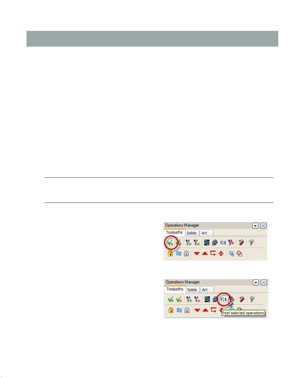
2 In the Toolpath Manager, click the Select
all operations button.
All five toolpath folders will display a check mark to indicate they are selected.
3 In the Toolpath Manager, click the Post
selected operations button. The Post
processing dialog box opens.
Page 52
46 • BASIC 2D MACHINING
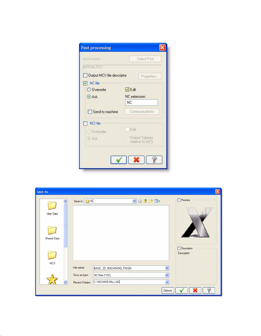
4 Set the post processing parameters as shown. These settings will ask if you want to save the
NC file and will display the resulting file in your default text editor.
5 Click OK. The Save As dialog box opens.
6 Click Save to save the NC file in the default location with the recommended file name.
Page 53
POSTING TOOLPATHS • 47
Notes:
• Posting may take several minutes. When it is complete, the NC code will display in your
default editor/communicator. This tutorial uses Mastercam Editor to display the NC code.
• Producing the correct NC code for your machine and application depends on properly
configuring the machine definition, control definition, and .PST file. For detailed
information on machine definitions, control definitions, and posting, please see the
following documentation supplied with Mastercam:
Mastercam Help
Mastercam X5 Reference Guide (choose Reference Guide from the Mastercam Help
menu)
Mastercam X5 NCI & Parameter Reference (in the Documentation folder under your
Mastercam installation folder)
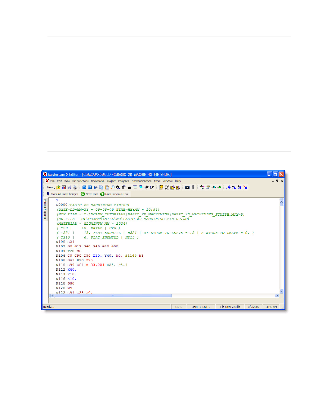
7 Your selected editor opens (in this case, Mastercam Editor), displaying the posted NC code.
8 Scroll through the NC code to verify that each line of code meets your expectations. Edit
and save as necessary.
Page 54

48 • BASIC 2D MACHINING
Post Processing Summary: Sending NC Files to Machine
IMPORTANT: This tutorial is based on the Mastercam Mill Default machine definition for
training purposes only. It is not possible to provide a step-by-step procedure for sending the
NC code to your machine control because machine setups are customizable and most likely
different from the machine definition used here. Following is a general description of how
the NC code is communicated to machines and their controls for machining.
After the NC file is reviewed, edited, and saved, you can set up your machine control to accept the
NC file. This is done according to your machine and control manufacturer’s procedures.
When the machine control is ready to receive the NC file, configure your preferred editor or
communications program to communicate with your machine control. Refer to your
communications program documentation for details.
Send the NC code to your machine control according to your machine and control manufacturer’s
documentation. Once you start the communication process, the send/receive data processing is
mostly managed by your machine control.
Contact your local Mastercam Reseller for customized machine/control definitions, post (PST)
files, and support.
Conclusion
Congratulations! You have completed the Basic 2D Machining tutorial. Now that you have mastered
the skills in this tutorial, we encourage you to explore Mastercam’s other features and functions.
Additional tutorials may be available in this or other series. Please contact your authorized
Mastercam Reseller for further training.
Page 55

Page 56

Attention! Updates may be available.
Go to Mastercam.com/Support for the latest downloads.
671 Old Post Road
Tolland, CT 06084 USA
www.mastercam.com
X5-PDF-TUT-2M
 Loading...