

Page 1
T E M / T E L
Installation & Operations Manual
LED Lighting
LED Lighting
LED LightingLED Lighting
Master-Bilt Products
908 Highway 15 North
New Albany, MS 38652
Phone: (800) 684-8988
PN 148-90000
REV 04-08-10_LN,BC
Page 2

2
Page 3

TABLE OF CONTENTS
INTRODUCTION .............................................................................................................................................................4
WARNING LABELS AND SAFETY INSTRUCTIONS ....................................................................................................5
PRE-INSTALLATION INSTRUCTIONS..........................................................................................................................6
Inspection for Shipping Damage ...............................................................................................................................6
INSTALLATION INSTRUCTIONS ..................................................................................................................................6
General Instructions ..................................................................................................................................................6
Store Conditions........................................................................................................................................................7
Location.....................................................................................................................................................................7
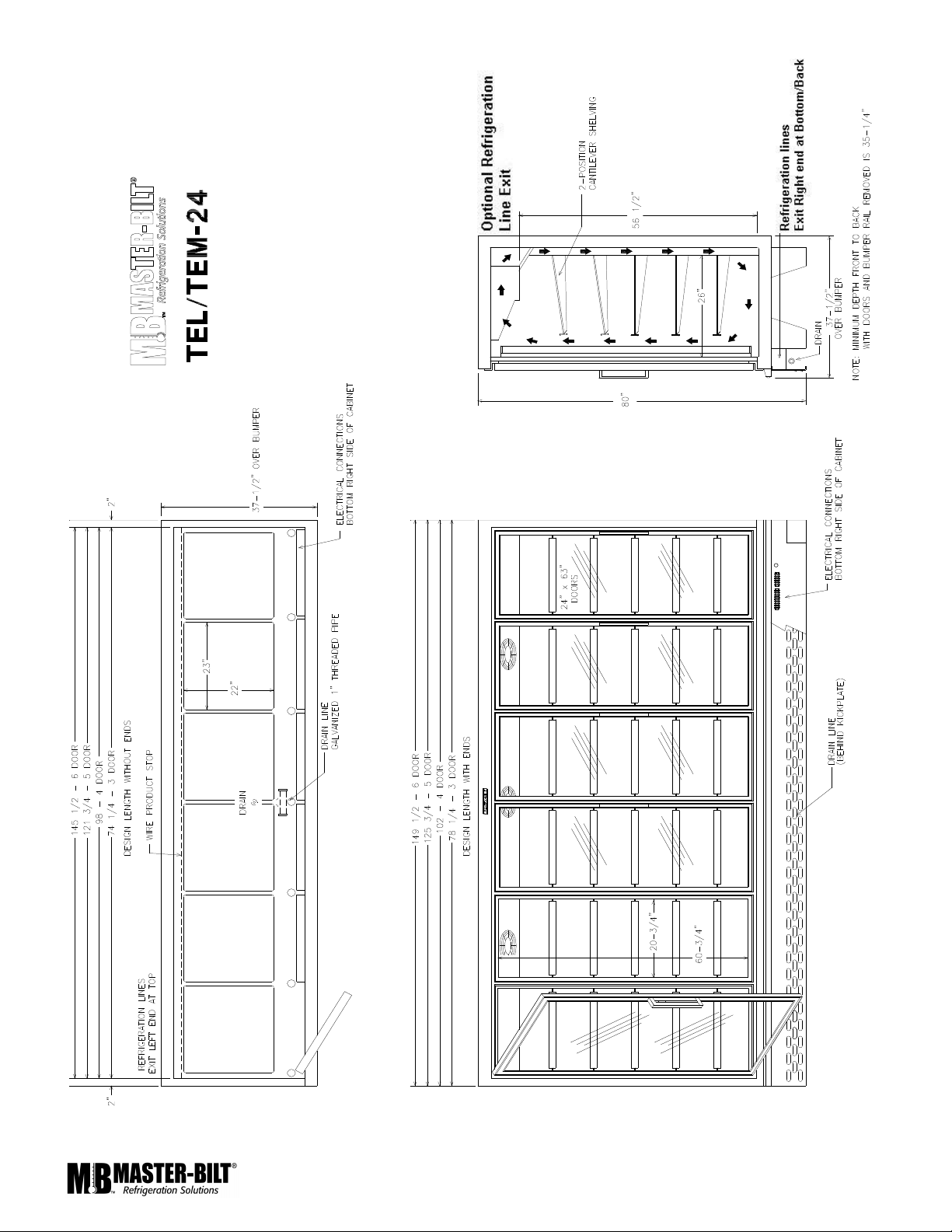
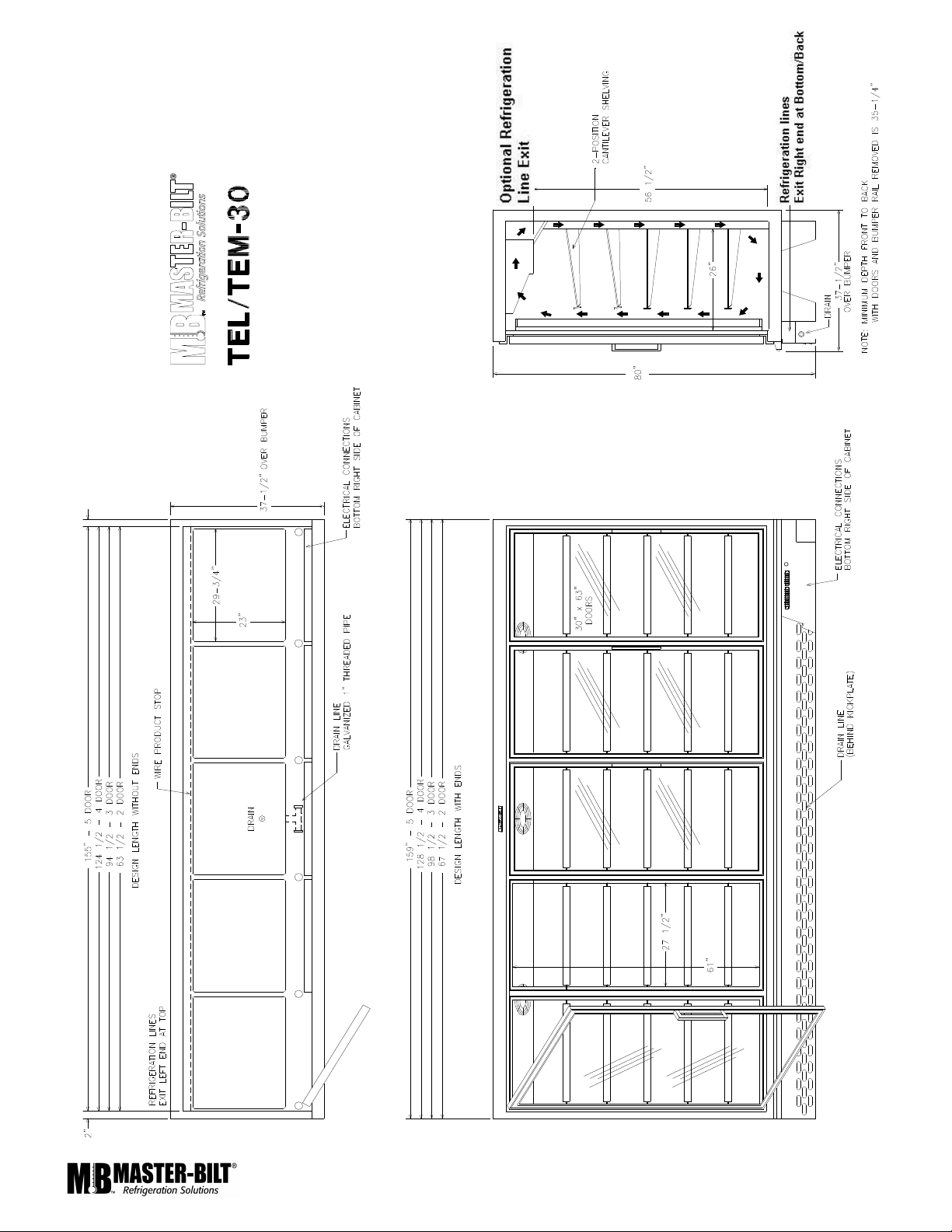
Dimensional Data...................................................................................................................................................8-9
Leveling...................................................................................................................................................................10
Joining Sections .................................................................................................................................................10-11
Removing and Replacing the Ends.........................................................................................................................11
Plumbing, TEM/TEL ................................................................................................................................................12
Electrical..................................................................................................................................................................12
Piping ......................................................................................................................................................................12
Refrigeration System Evacuating and Charging .....................................................................................................13
Defrost Termination/Temperature Control ..............................................................................................................13
Control Settings.......................................................................................................................................................13
STARTING PROCEDURE ............................................................................................................................................13
FINAL CHECK LIST......................................................................................................................................................14
DOOR FRAMES AND DOORS.....................................................................................................................................14
Door Plastic (Gasket Retainer) Replacement .........................................................................................................14
Door Gasket Replacement......................................................................................................................................14
LED Driver Replacement ........................................................................................................................................14
Door Heater Replacement ......................................................................................................................................14
SERVICE INSTRUCTIONS ...........................................................................................................................................15
MASTER-BILT PART NUMBERS ................................................................................................................................16
SALE AND DISPOSAL .................................................................................................................................................17
WIRING DIAGRAMS................................................................................................................................................18-29
TEL/TEM CONDENSING UNIT SIZING CHART………………………………………………………………………..…...30
3
Page 4
INTRODUCTION
Thank you for purchasing a Master-Bilt cabinet. This manual contains important instructions for installing, using and
servicing a Master-Bilt TEL/TEM Top Coil Endless Case. A parts list is included in with this manual. Read all these
documents carefully before installing or servicing your equipment.
NOTICE
Read this manual before installing your cabinet. Keep the manual and refer to it before doing any service on the
equipment. Failure to do so could result in personal injury or damage to the cabinet.
DANGER
Improper or faulty hook-up of electrical components of the refrigeration units can result in severe injury or
death.
All electrical wiring hook-ups must be done in accordance with all applicable local, regional or national
standards.
NOTICE
Installation and service of the refrigeration and electrical components of the cabinet must be performed by a
refrigeration mechanic and/or a licensed electrician.
The portions of this manual covering refrigeration and electrical components contain technical instructions intended only
for persons qualified to perform refrigeration and electrical work.
This manual cannot cover every installation, use or service situation. If you need additional information, call or write us:
Customer Service Department
Master-Bilt Products
Highway 15 North
New Albany, MS 38652
Phone (800) 684-8988
Fax (800) 684-8988
4
Page 5
WARNING LABELS AND SAFETY INSTRUCTIONS
This symbol is the safety-alert symbol. When you see this symbol on your cabinet or in this
manual, be alert to the potential for personal injury or damage to your equipment.
Be sure you understand all safety messages and always follow recommended precautions
and safe operating practices.
NOTICE TO EMPLOYERS
You must make sure that everyone who installs, uses or services your cabinet is thoroughly familiar with all
safety information and procedures.
Important safety information is presented in this section and throughout this section and throughout the manual. The
following signal words are used in the warnings and safety messages:
DANGER: Severe injury or death will occur if you ignore the message.
WARNING: Severe injury or death can occur if you ignore the message.
CAUTION: Minor injury or damage to your cabinet can occur if you ignore the message.
NOTICE: This is important installation, operation or service information. If you ignore the message,
you may damage your cabinet.
The warning and safety labels shown throughout this manual are placed on your Master-Bilt Products cabinet at
the factory. Follow all warning label instructions. If any warning or safety labels become lost or damaged, call
your customer service department at (601) 534-9061 for replacements.
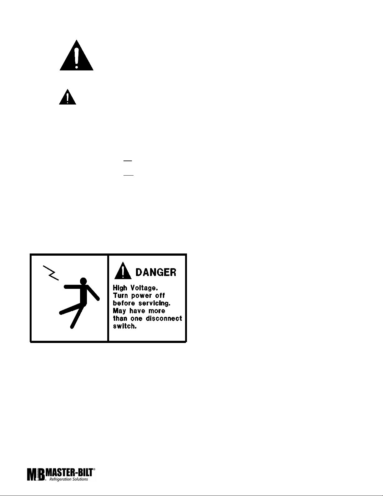
This label is located on top of the electrical control
panel and on the wiring channel.
5
Page 6

PRE-INSTALLATION INSTRUCTIONS
INSPECTION FOR SHIPPING DAMAGE
You are responsible for filing all freight claims with the delivering truck line. Inspect all cartons and crates for damage as
soon as they arrive. If damage is noted to shipping crates or cartons or if a shortage is found, note this on the bill of
lading (all copies) prior to signing.
If damage is discovered when the cabinet is uncrated, immediately call the delivering truck line and follow up the call with
a written report indicating concealed damage to your shipment. Ask for an immediate inspection of your concealed
damage item. Crating material must be retained to show the inspector from the truck line.
INSTALLATION INSTRUCTIONS
GENERAL INSTRUCTIONS
1. Be sure the equipment is properly installed by competent service people.
2. Keep the equipment clean and sanitary so it will meet your local sanitation codes. Wipe up all spills, clean with
water and a mild detergent, then rinse with clean water.
3. Rotate your stock so that older stock does not accumulate. This is especially important for ice
cream. A "First-In, First-Out" rotation practice will keep the products in good salable condition.
4. Do not place product in the case when it is soft or partially thawed. Also, product should not be put in the case for
at least 6 hours after it is started.
5. Stock cases as quickly as possible, exposing only small quantities to store temperatures for short periods of time.
6. When replacing burned out fluorescent tubes, be sure that the electrical power to the lighting circuit is turned off.
To comply with N.S.F. requirements, this cabinet must be sealed to the floor with NSF listed silicone
sealant. Before moving cabinet into place, route cabinet plumbing with P-trap to store drain line or install optional
condensate pan.
6
Page 7
STORE CONDITIONS
The Master-Bilt TEL/TEM cases are designed to operate in the controlled environment of an air conditioned store. The
store temperature should be at or below 75°F and a relative humidity of 55% or less. At higher temperature or humidity
conditions, the performance of these cases may be affected and the capacity diminished. It is not uncommon in a newly
constructed store for the temperature and humidity to be above design conditions. These excessive conditions may
produce sweating in the case until the store is operational and the ambient environment is more desirable.
LOCATION
The Master-Bilt TEL/TEM should not be positioned where it is directly
exposed to rays of the sun or near a direct source of radiant heat or air
flow.
Cabinet should not be built into an enclosed area. If this case is to be
located against a wall there should be at least a 4” space between the
wall and the back of the case, with 4” open space at top and one or both
ends. This space will allow for the circulation of air behind the case
which will prevent condensation on the exterior surfaces.
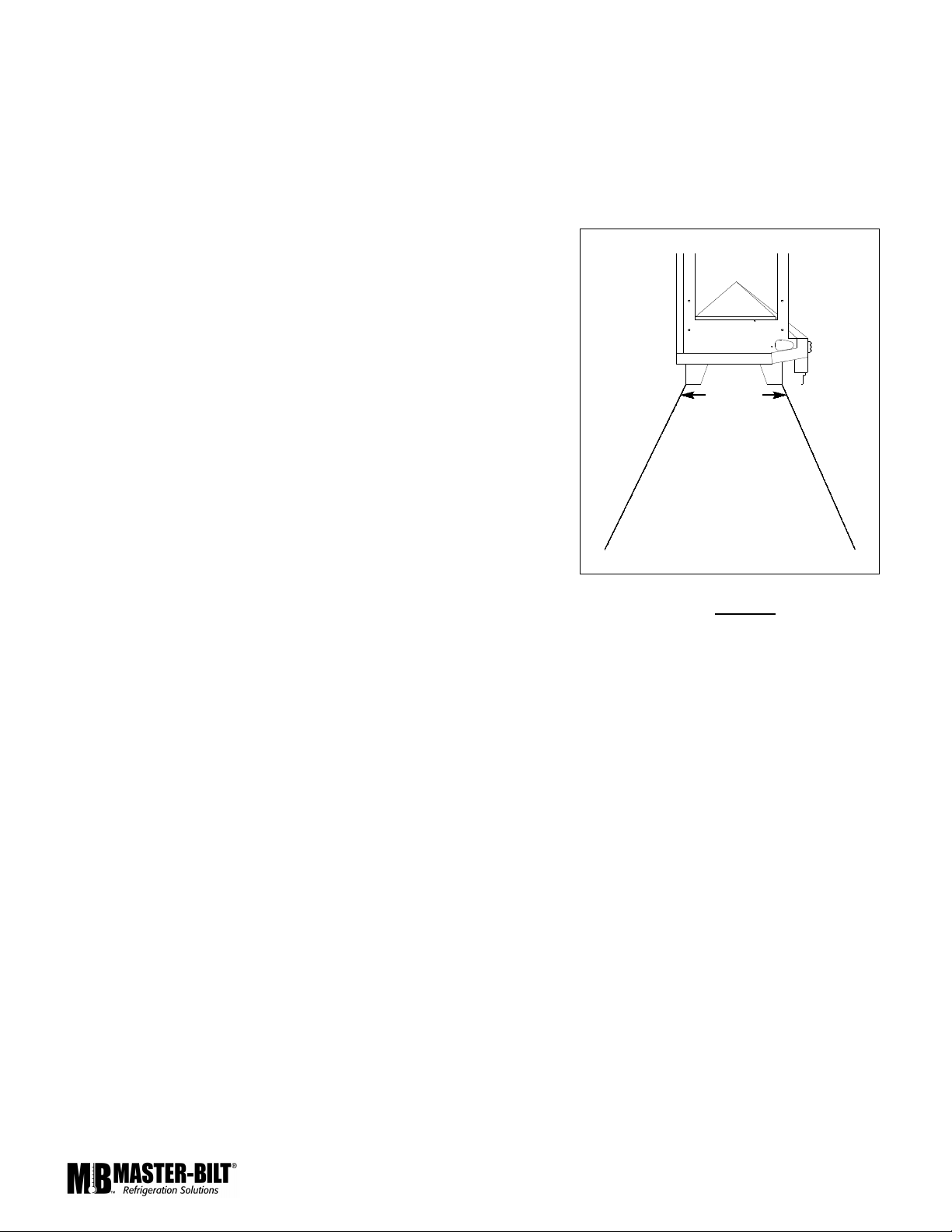
Make sure that the floor that will support this equipment is of adequate
strength to prohibit sagging. After confirming the dimensions of case with
the blueprint measure off and mark on the floor the exact location of the
cases for the entire lineup. Snap chalk lines where the base skids of the
case are to be located as shown in Figure 1.
Figure 1
7
Page 8
8
Page 9
9
Page 10

LEVELING
It is very important that this equipment be perfectly level. This will allow for proper and complete drainage of the
evaporator coil and for proper case alignment. A perfectly level area is generally not available where the equipment is to
be installed. Mark the location of all case joining points front and back. Use a transit to locate the highest point on the
chalk lines. This point will be a reference point for determining shim-pack heights. Using the reference point, mark the
difference directly on the floor to each joining point front and back. Shim each joining point to equal the reference point
as required. Tape all shims in place. If the installation is an entire lineup install the case that will be positioned at the
highest point first. Check that the equipment in the lineup is level as the installation proceeds.
JOINING SECTIONS, TEL/TEM
Remove the case from its shipping skid. Set the first case
into its desired position with required shims in preparation
for joining it with its adjacent case.
The joining gasket for cases in a lineup is factory installed
and is shown in balck in Figure 2. This gasket is only
required on one end of cases in a lineup as only one
gasket is needed between two cases. Inspect the gasket to
insure that it is properly located and is not damaged.
Remove the protective covering on the outside face of the
adjoining tape. The cases are now ready to be joined
together. Remove the second case from its shipping skid,
remove the “X” braces from the open end of the sections,
and move it into position against the end of the first case.
Properly level the second case with the appropriate shims
Bolt the cases together through the eight holes that are
provided in the aluminum triangular gussets as shown in
Figure 4. Tighten the bolts until all seams are fully closed.
Do not over tighten.
Figure 4
GASKET
SUPPORT POST
DOOR FRAME
To join the door frames, drill through the support posts with 9/64”
drill, using countersunk holes as a guide. Use the long screws (in
the bag tied to the door handle) to draw the frames together. See
Figure 5.
Figure 5
10
Page 11

INSTALLING THE ENDSKIRTS AND KICKPLATE
The kickplate should be installed prior to attaching the
endskirts. Secure the kickplate to the flange of the wire
raceway using the supplied sheet metal screws. Use the
supplied #10x1/2 self drilling screws to secure the kickplate to
the bottom face of the frame. The bottom of the kickplate
should be in contact with the floor. Refer to Figure 7 for the
placement of the Kickplate.
The endskirt will attach to the ends of the lineup using the
supplied #10x1/2 self drilling screws as shown in Figure 7.
Figure 7
INSTALLING JOINING TRIM, TEM/TEL
To install the top joiner, position the joiner over the void
between the cabinets, then slide the joiner down between the
350-10092
door frame and the cabinet as shown in Figure 8.
To install the bumper joiner, pry the end of the vinyl trim away
from the aluminum bumper extrusion until the first screw
holding the extrusion to the bumper is accessable with a
screwdriver. Loosen the screw on each section. Slide the
joiner between the aluminum extrusion and the bumper.
Tighten the screws. Using a wood block or mallet, tap the
vinyl extrusion back into place.
See Figure 8.
Figure 8
REMOVING AND REPLACING THE ENDS, TEL/TEM
The ends of a TEL/TEM are lag bolted to the ends of the
cabinet itself. Care should be taken not overtighten the
lag bolts. This could lead to stripping the holding material
inside the cabinet. Consult the factory if it is necessary to
remove or replace the end of a TEL/TEM.
350-10091
1
2
3
351-12504
11
Page 12

PLUMBING, TEL/TEM
The TEL/TEM is equipped with a condensate drain that is piped out the middle front of the cabinet. This drain line is 1”
galvanized pipe that must be have a P-trap installed. It is very important that this trap be installed as it will result in
diminished performance of the case without it. There is also a 1” cleanout drain in the middle of the bottom the cabinet.
This drain is plumbed to the front of the bottom of the cabinet. The kickplate may have to be removed to see the piping
for the cleanout drain.
1. Always install drains in accordance with local codes.
2. Use largest possible size pipe for drains, one inch minimum is recommended.
3. Provide as much downhill slope as possible.
4. Prevent drains from freezing. Do not install drains in contact with uninsulated suction lines.
NOTICE TO STORE OWNERS / MANAGERS
Moisture or liquid around or under the cabinet is a potential slip/fall hazard for persons walking by or working in
the general area of the cabinet. Any cabinet malfunction or housekeeping problem that creates a slip/fall hazard
around or under the cabinet should be corrected immediately.
If moisture or liquid is observed around or under a Master-Bilt cabinet, an immediated investigation should be made by
qualified personnel to determine the source of the moisture or liquid. The investigation should determine if the cabinet is
malfunctioning or if there is a drain pipe leaking.
ELECTRICAL
WARNING
Before servicing electrical components in the case or the doors or door frames make sure all power to case is
off. Always use a qualified technician.
It is very important that full voltage and overcurrent protection requirements for condensing units, defrost heaters, fans,
door and frame heaters, etc. be provided at installation. Wire sizing must be adequate to maintain full voltage under
amperage loads specified in the charts are in this manual.
PIPING
The piping connections for a TEL/TEM are piped out of the cabinet to the customer’s specifications. These lines have
been capped and should be cut with a tubing cutter so as not to introduce copper shavings into the system. Only clean,
dry, sealed refrigeration grade AC hard copper tubing should be used. Be sure to install a suction line oil trap or ‘P-trap
for both the TEL/TEM’s. It is recommended that all brazed joints be made with silver alloy-type solders. For roof top
condensing units, an inverted P-trap must be installed in the suction line where the refrigeration lines exit onto the roof.
For vertical line runs of more than 20 ft., a riser trap must be installed at the approximate center of the riser. The
condensing unit should be located as closely as possible to the cabinet. Keep the refrigeration lines as short as possible
and use as few fittings as practicable, being especially careful not to “kink” the lines. Keep the layouts as simple as
possible and properly support the piping to absorb vibratioin and the normal expansion and contraction caused by
temperature changes. All suction lines should be well-insulated to minimize heat absorption and control condensate
which could form on the suction line. If tubular insulation is used, the ends, joints, and any other open areas (including
slits necessary to fit the tubing over installed piping) should be sealed with insulation glue. A minimum amount of flux
should be used as needed and a small amount of dry nitrogen should be fed into the tubing during brazing to minimize
formation of scale and oxidation inside the tubing. Leak check all joints with an electronic leak detector or halide torch. If
leaks are found relieve the pressure and make repairs as necessary and recheck. Thoroughly caulk or foam all
refrigeration line entry holes. All openings for wiring should be sealed with NSF listed sealant to prevent air leaks and
unwanted condensation.
12
Page 13

REFRIGERATION SYSTEM EVACUATING AND CHARGING
1. Blow out all refrigerant lines with dry nitrogen or carbon dioxide to eliminate the possibility of
dirt, scale, etc. remaining inside.
2. Connect all lines and leak test all connections.
3. Connect a good high vacuum pump to both the low and high side evacuation valves.
4. Operate the pump until a vacuum of 1500 microns (0.06 inches of mercury) absolute pressure is obtained. At this
point, the vacuum should be broken by the introduction of refrigerant into the system, through a drier, until the
pressure is brought up to zero pounds gauge. Repeat this procedure two more times. During the final evacuation, a
vacuum of 500 microns (0.02 inches of mercury) absolute pressure should be obtained. After this vacuum is
reached, the system can be fully charged with refrigerant.
DEFROST TERMINATION/ TEMPERATURE CONTROLS
For a TEL/TEM, the controls are located at the top of the cabinet on the right hand side. Nothing will have to be removed
to access the controls.
The temperature control is adjusted by simply turning the knob clockwise for a colder case and counter-clockwise for a
warmer case. The defrost termination control sensor is
mounted directly on the end plate of the coil. This control determines how long the defrost cycle will last. By adjusting the
defrost termination control clockwise the defrost cycle will be shortened. By adjusting the defrost termination control
counter-clockwise the defrost cycle will become longer.
CONTROL SETTINGS
TEL (Low Temp) TEM (Med Temp)
Temperature Control
Condensing Unit Time Clock 4 times/day (6hours);
Condensing Unit Low Pressure Control Cut in 20 lbs: Diff. 18 lbs. Cut in 35 lbs: Diff. 25 lbs.
Condensing Unit High Pressure Control 400 lbs 380 lbs
Defrost Termination
*This is a standard setting; climates with extreme humidity may require more defrost times or longer fail safe
settings.
-25 - +22°°°°F 32 - 51°°°°F
40 minutes fail safe*
40 - 75°°°°F
N/A
N/A
STARTING PROCEDURE
1. Check the temperature holding range against the control setting.
2. Check the defrost control system to see that all ice is removed from the coil during each defrost cycle.
3. Check pressures.
4. Check EPR Valve for proper pressure when applicable.
13
Page 14

FINAL CHECK LIST
A. Check high-low pressure control settings.
B. Check setting of defrost timer:
1. Four defrost/24 hours, with 30 minute fail safe.
C. Check operating pressure.
D. Check electrical requirements of unit to supply voltage.
E. Set temperature control for desired temperature range.
F. Check setting of thermostatic expansion valve for proper operation. Approx. 10°F superheat.
G. Check sight glass for proper refrigerant charge.
H. Check system for proper defrost settings and operation.
I. Check condensing unit for vibrating or rubbing tubing. Dampen and clamp as required.
J. All valves should be completeley open counter-clockwise.
K. Check packing nuts on all service valves.
L. Replace all service valve caps and latch unit covers.
M. Check refrigeration line for proper P-traps and proper locations.
N. Check drain for proper P-traps and proper locations.
DOOR PLASTIC (GASKET RETAINER) REPLACEMENT
Starting in corner, gently pull the rubber gasket away from the door plastic. With gasket removed, insert a flat-head
screwdriver under the outside edge of the plastic, and gently pry up. At either end of the plastic run the screwdriver the
complete length and width of the door rail. With the outside edge of the plastic released, push the plastic towards the
glass to remove. To replace, insert the edge of the plastic into the inside door rail groove. Snap the outside edge of the
plastic cover over the outside edge of the door rail.
DOOR GASKET REPLACEMENT
Remove the old gasket by starting in the corner, gently pulling gasket away from the plastic. To replace the gasket,
remove the top and bottom door plastic, and slide the gasket up the two verticals. Slide the top and bottom plastic onto
the gasket, and replace the top and bottom plastic on the door rail. Tuck in the corners of the gasket with a flat-head
screwdriver.
LED DRIVER REPLACEMENT, TEL/TEM
For a TEL/TEM, the LED Drivers are located inside the door mullions and can be accessed from the front of the door
frame. Remove the door that hinges on the mullion where the ballast will be replaced. From the front of frame, remove
contact plate & retainer by inserting a flat-head screwdriver under back edge of black contact plate retainer, and gently
pull to unsnap retainer from the mullion. Repeat for the other side, and remove the contact plate. With the ballast now
exposed, remove the screw on the top end of the ballast. Loosen the screw on the bottom of the driver.
Disconnect all lead wires by separating the connectors. If cut, leave enough lead wire to re-connect the new driver with a
wire nut. Insert the bottom of the new ballast in the punched tabs and re-install the top screw in the top end of the driver.
Tighten both screws. Re-connect new driver’s lead wires following the wiring diagrams provided.
DOOR HEATER REPLACEMENT
Remove door gasket and plastic. Remove the center side access plate located on the side of the door. The wiring for
the door is done in the center side of the hinge rail. To remove the heater, unplug the solid lead wires: Black or Red,
White, and Green/Yellow (ground). If the glass is heated, unplug the Black and White solid wires from the glass. Heater
wire lies in track on the back outside edge of door. Pull the heater out. Reverse instructions to replace the door heater.
Plug in Black or Red lead wire from hinge pin to Black or Red lead wire from heater, White lead wire from hinge pin to
White heater lead, and Green/Yellow lead from hinge pin to ground.
Note: If glass is heater, plug in Black and White lead wires coming off heater loom to Black and White lead wires from
glass. Replace side access plate. Replace the door plastic and gasket.
14
Page 15

SERVICE INSTRUCTIONS (Trouble Shooting Guide)
1. High head pressure and high back pressure:
A. Condenser coil clogged or restricted.
B. Condenser fan motor defective.
2. Low back pressure and low head pressure:
A. Restriction in system.
B. Refrigerant undercharged.
C. Leak in system.
3. Pressures normal – cabinet warm:
A. Coil blocked with frost or ice (see #4).
B. Refrigerant undercharged.
C. Control set too warm.
D. Air screen disturbance.
4. Coil blocked with frost or ice:
A. Defective temperature control. E. P-trap in drain not installed.
B. Time clock not operating properly. F. Doors aren’t sealing when closed.
C. Improper time clock setting. G. Air screen disturbance.
D. Ambient conditions above 75°F/55% RH. H. Evaporator fan motor defective.
E. Defrost heater not operating. I. Low voltage.
5. Compressor starts and runs – but cycles on overload:
A. Low voltage.
B. Dropped phase (3 phase).
C. Overload protector defective.
D. High head pressure (see#1).
6. Compressor will not start – hums, but cycles on overload:
A. Low voltage.
B. Relay defective.
C. Overload defective.
D. High head pressure (see #1).
7. Special service situations:
If moisture or liquid is observed around or under a Master-Bilt cabinet, an immediate investigation should be
made by qualified personnel to determine the source of moisture or liquid. The investigation made should
determine if the cabinet is malfunctioning or if there is a simple housekeeping problem.
Moisture or liquid around or under a cabinet is a potential slip/fall hazard for persons walking by or working in the
general area of the cabinet.
Any cabinet malfunction or housekeeping problem that creates a slip/fall hazard around or under a cabinet should
be corrected immediately.
15
Page 16

MASTER-BILT PART NUMBERS
The table below gives Master-Bilt part numbers. Use this chart when ordering replacement parts for your TEL/TEM
cases.
Description TEL (Low Temp) TEM (Med Temp
Evaporator Coil Consult Factory
Expansion Valve
Defrost Heater Consult Factory N/A
Drain Line Heater
Heater Safety
Defrost Termination/Fan Delay
Temperature Control
Evaporator Fan Motor
Evaporator Fan Blade 15-01184 15-01184
Evaporator Fan Guard 25-00205 25-00205
Drum Thermometer 19-13586 19-13586
Standard Shelf
Wire Cantilever
Door Frame Consult Factory
Standard Door (Black)
Anthony Model 101
Ballast
Ballast Driver
Anthony LED CONVERTOR
LED Mullion light bar
Anthony Low powe 4100K
Lamp Left Side light bar
Anthony Low power 4100K
Lamp Right Side light bar
Anthony Low power 4100K
Light Switch
Anthony ELS/Connexxion
Door Gasket
Anthony
Torque-Master (Black)
Anthony
Torque Rod
Top Hinge Pin
Anthony
Lamp Holder
Anthony ELS
Lamp Holder
Anthony Connexxion Top
Lamp Holder
Anthony Connexxion Bottom
Connector w/wire
Lens Bridge
Anthony ELS/Connexxion
Prismatic Lens
Anthony ELS/Connexxion
Flourescent Lamp
Anthony ELS/Connexxion
Single Station Socket 23-01494 23-01494
Double Station Socket 23-01493 23-01493
Door Frame Heater, Mullion
Door Frame Heater, Top
Door Frame Heater, Bottom
Texas Instruments #500971
09-09634
Sporlan SBFSE-A-ZP
17-09063
230V / 6 ½ Watts
19-01307
19-00890
Ranco #F-25-118-0
19-13607
Eaton 9540
13-00683
208-230V / 1550 RPM
33-01385 33-01385
31-02207 (30”)
31-02225 (24”)
23-01458 (1 Lamp)
23-01480 (2 Lamp)
23-01730 23-01730
23-01727
Anthony
23-01728
Anthony
23-01729
Anthony
19-13685
Anthony F-12486
37-01273 (30”)
37-01280 (24”)
35-01464
Anthony F-122R-B
35-01456
Anthony D-64203
35-01484
Anthony D-64238
23-01615
Anthony AE-11028
23-01616
Anthony AE-12797
23-01617
Anthony AE-12796
23-01618
Anthony XX-13246
23-01619
Anthony AE-72661
23-01620
Anthony AE-72419
23-01585
Anthony AE-72139
Consult Factory
Sporlan SBFVE-A-C
23-00360 (1 Lamp)
Ranco A30-1762
120 V / 1550 RPM
31-02212 (30”)
31-02230 (24”)
Anthony F-12486
37-01273 (30”)
37-01280(24”)
Anthony F-122R-B
Anthony D-64203
Anthony D-64238
Anthony AE-11028
Anthony AE-12797
Anthony AE-12796
Anthony XX-13246
Anthony AE-72661
Anthony AE-72419
Anthony AE-72139
09-09631
N/A
N/A
N/A
19-00884
13-00685
23-01727
Anthony
23-01728
Anthony
23-01729
Anthony
19-13685
35-01464
35-01456
35-01484
23-01615
23-01616
23-01617
23-01618
23-01619
23-01620
23-01585
)
16
Page 17

SALE AND DISPOSAL
OWNER RESPONSIBILITY
If you sell or give away your Master-Bilt cabinet you must make sure that all safety labels and the Installation - Service
Manual are included with it. If you need replacement labels or manuals, Master-Bilt will provide them free. Contact the
customer service department at Master-Bilt at (800) 684-8988.
The customer service department at Master-Bilt should be contacted at the time of sale or disposal of your cabinet so
records may be kept of its new location.
If you sell or give away your Master-Bilt cabinet and you evacuate the refrigerant charge before shipment, Master-Bilt
recommends that the refrigerant charge be properly recovered in complience with section 608 of the Clean Air Act
effective November 1995 and in accordance with all applicable local, regional, or national standards.
17
Page 18

18
Page 19

19
Page 20

20
Page 21

21
Page 22

22
Page 23

23
Page 24

24
Page 25

25
Page 26

26
Page 27

27
Page 28

28
Page 29

29
Page 30

REQUIRED CONDENSING UNITS FOR TEM/TEL SERIES
NO. OF
DOORS
2
3
4
5
6
7
8
9
10
11
12
13
14
15
16
17
18
19
20
21
22
23
24
25
35°F AVERAGE PRODUCT TEMP.
+20°F SUCTION
75°F AIR CONDITIONED STORE
55% RELATIVE HUMIDITY
COND. UNIT REQUIRED FOR
AIR TEMP. ENTERING CONDENSER*
90°F 100°F 110°F 90°F 100°F 110°F 90°F 100°F 110°F
MHHZ0071B MHHZ0071B MHHZ0071B MHLZ0071 MHLZ0071 MHLZ0071 MHLZ0091 MHLZ0091 MHLZ0091
MHHZ0071B MHHZ0071B MHHZ0071B MHLZ0071 MHLZ0091 MHLZ0091 MHLZ0091 MHLZ0121 MHLZ0121
MHHZ0071B MHHX0081B MHHX0081B MHLZ0091 MHLZ0091 MHLZ0121 MHLZ0121 MHLZ0121 MHLZ0121
MHHZ0081B MHHZ0081B MHHZ0111 MHLZ0091 MHLZ0121 MHLZ0121 MHLZ0121 MSLZ0151 MSLZ0181
MHHZ0111 MHHZ0111 MHHZ0111 MHLZ0121 MHLZ0121 MSLZ0151 MSLZ0151 MSLZ0181 MSLZ0221
MHHZ0111 MHHZ0111 MHHZ0171 MHLZ0121 MSLZ0151 MSLZ0181 MSLZ0181 MSLZ0221 MSLZ0221
MHHZ0171 MHHZ0171 MHHZ0171 MSLZ0151 MSLZ0181 MSLZ0181 MSLZ0221 MSLZ0221 MSLZ0221
MHHZ0171 MHHZ0171 MHHZ0191 MSLZ0181 MSLZ0181 MSLZ0221 MSLZ0221 MSLZ0221 BSLZ0750
MHHZ0171 MHHZ0191 MHHZ0191 MSLZ0181 MSLZ0221 MSLZ0221 MSLZ0221 BSLZ0750 BSLZ0750
MHHZ0191 MHHZ0191 MHHZ0221 MSLZ0221 MSLZ0221 MSLZ0221 BSLZ0750 BSLZ0750 BSLZ0750
MHHZ0191 MHHZ0221 MHHZ0221 MSLZ0221 MSLZ0221 BSLZ0750 BSLZ0750 BSLZ0750 BSLZ1000
MHHZ0191 MHHZ0221 MHHZ0251 MSLZ0221 BSLZ0750 BSLZ0750 BSLZ0750 BSLZ1000 BCLZ0750
MHHZ0221 MHHZ0251 MHHZ0251 BSLZ0750 BSLZ0750 BSLZ0750 BSLZ1000 BSLZ1000 BSLZ1500
MHHZ0251 MHHZ0251 MHHZ0301 BSLZ0750 BSLZ0750 BSLZ1000 BSLZ1000 BSLZ1000 BSLZ1500
MHHZ0251 MHHZ0251 MHHZ0301 BSLZ0750 BSLZ1000 BSLZ1000 BSLZ1000 BSLZ1500 BSLZ1500
MHHZ0251 MHHZ0301 MHHZ0331 BSLZ0750 BSLZ1000 BSLZ1000 BSLZ1500 BSLZ1500 BSLZ1500
MHHZ0301 MHHZ0301 MHHZ0331 BSLZ1000 BSLZ1000 BSLZ1500 BSLZ1500 BSLZ1500 BSLZ1500
MHHZ0301 MHHZ0331 MHHZ0331 BSLZ1000 BSLZ1000 BSLZ1500 BSLZ1500 BSLZ1500 BSLZ1500
MHHZ0301 MHHZ0331 MHHZ0431 BSLZ1000 BSLZ1500 BSLZ1500 BSLZ1500 BSLZ1500 BCLZ1500
MHHZ0331 MHHZ0331 MHHZ0431 BSLZ1000 BSLZ1500 BSLZ1500 BSLZ1500 BSLZ1500 BCLZ1500
MHHZ0331 MHHZ0431 MHHZ0431 BSLZ1500 BSLZ1500 BSLZ1500 BSLZ1500 BCLZ1500 BCLZ1500
MHHZ0331 MHHZ0431 MHHZ0431 BSLZ1500 BSLZ1500 BSLZ1500 BSLZ1500 BCLZ1500 BCLZ1500
MHHZ0431 MHHZ0431 MHHZ0431 BSLZ1500 BSLZ1500 BSLZ1500 BCLZ1500 BCLZ1500 BCLZ1500
MHHZ0431 MHHX0441 MHHZ0501 BSLZ1500 BSLZ1500 BSLZ1500 BCLZ1500 BCLZ1500 BCLZ1500
-3°F AVERAGE PRODUCT TEMP.
-11°F SUCTION
75°F AIR CONDITIONED STORE
55% RELATIVE HUMIDITY
COND. UNIT REQUIRED FOR
AIR TEMP. ENTERING CONDENSER*
-12°F AVERAGE PRODUCT TEMP.
-18°F SUCTION
75°F AIR CONDITIONED STORE
55% RELATIVE HUMIDITY
COND. UNIT REQUIRED FOR
AIR TEMP. ENTERING CONDENSER*
 Loading...