

Page 1
Master
-
Bilt Electronic Superheat Controller Bulletin
5/16 Rev. B 57
-
02155
Page 1
Application and Installation Bulletin for Master-Bilt® Refrigeration
Superheat Controller Kit Assembly(A900-22007), 120/208/240/1/60, R404A,
LT/MT APPS
Introduction
The superheat controller is designed to control Master-Bilt made evaporator
system to replace the mechanical thermal expansion valve. Each Master-
®
Refrigeration Superheat Controller Kit contains a Master-Bilt®
Bilt
Superheat Controller, one electric expansion valve, one pressure transducer,
one temperature sensor and one 24VAC/40VA, 120/208/240 V primary input
transformer.
Since it is a TRUE SUPERHEAT control, the evaporator will achieve the highest
possible efficiency. The unique design of the control algorithm also permits the
compressor head pressure to be free floated within its operating range with
variable ambient temperature. Therefore, the refrigeration system in low ambient
condition can achieve the highest possible Energy Efficiency Ratio.
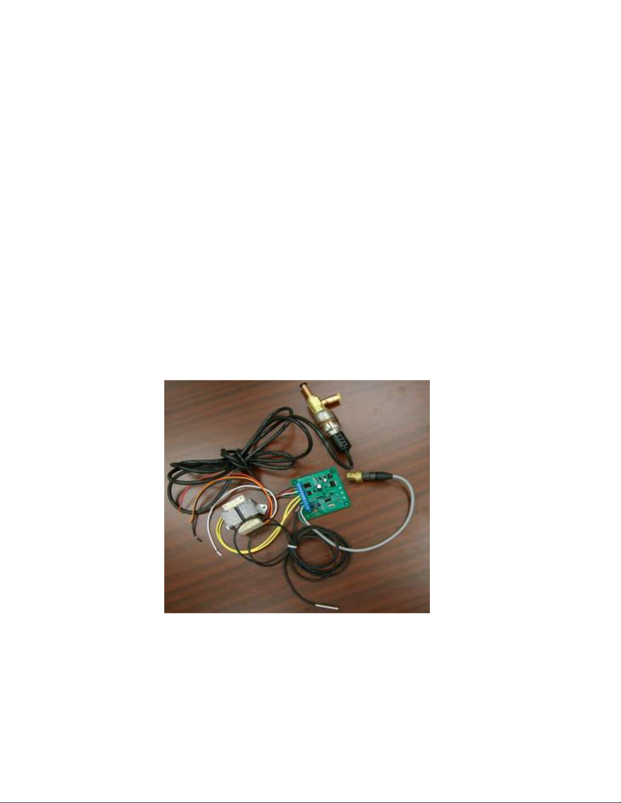
Below Picture 1 shows the basic components in this control kit.
Picture 1. Superheat Controller Kit
Page 2
Master
-
Bilt Electronic Superheat Controller Bulletin
Page 2
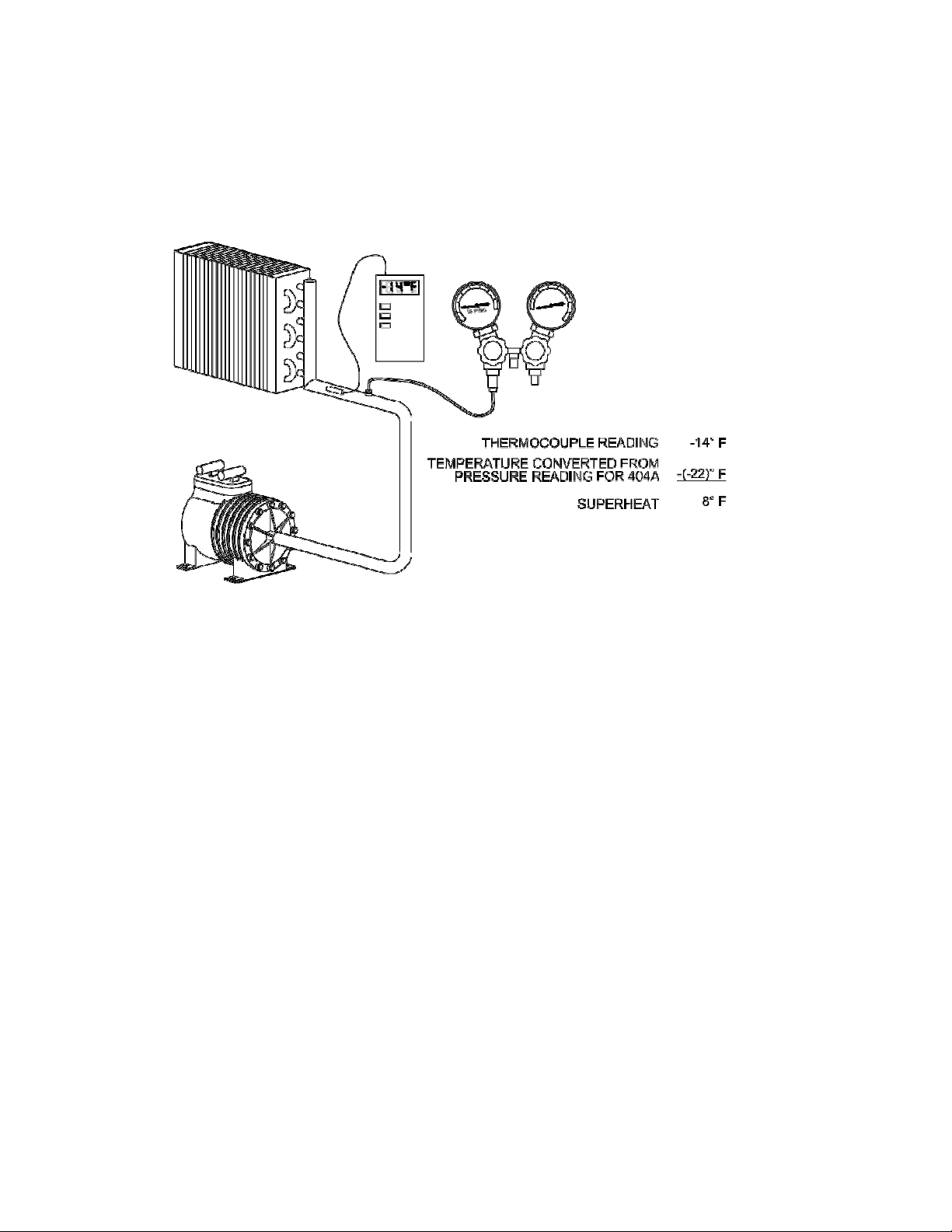
True Superheat Control
Picture 2 below shows us how TRUE SUPERHEAT is measured at a freezer
evaporator.
Picture 2
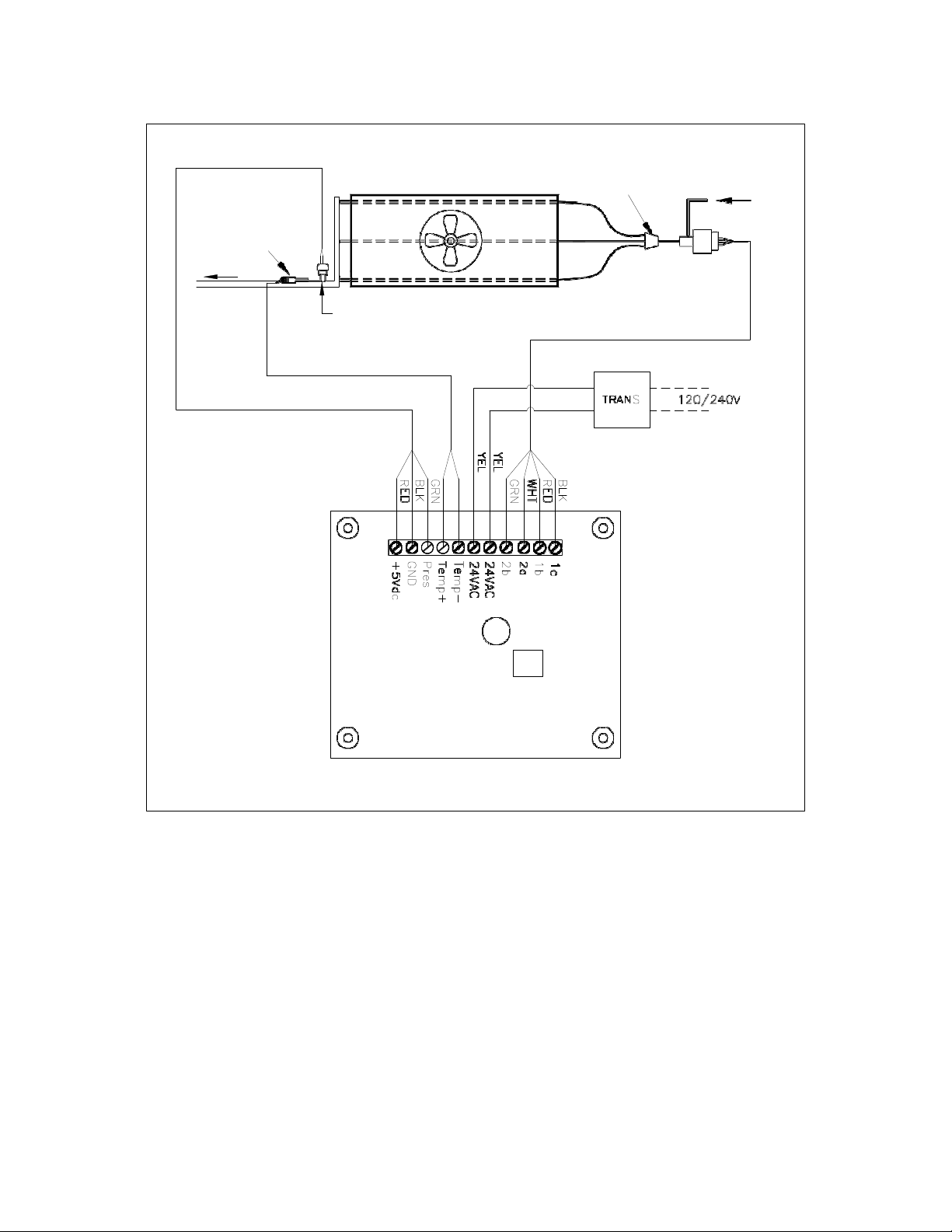
Picture 3 is the control schematic drawing to show us how the Master-
®
Bilt
electronic superheat controller works.
The suction pressure transducer is mounted at suction line or header to measure
the evaporating pressure. The controller stores the P-T chart of Refrigerant
R404A and converts the suction pressure into saturated temperature. For
example, if the pressure is 15.0 PSIG, the saturated or evaporating temperature
is about -22
o
F.
The suction outlet temperature sensor is mounted on the suction line about 4 to
6” outside the evaporator to measure the superheated vapor temperature. In this
o
case, if the suction outlet temperature is measured -14
F, the evaporator TRUE
SUPERHEAT is the suction outlet temperature minus the evaporating
o
temperature, or -14
F –(-22oF) = 8oF.
Page 3
Master
-
Bilt Electronic Superheat Controller Bulletin
Page 3
Evaporator
Distributor
Liquid Line
Suction
Temp Sensor
Suction Line
Electric
Expansion
Valve
Pressure
Transducer
SUPERHEAT CONTROLLER
MB P/N: 19
-
14221
Superheat is the measurement of level of liquid refrigerant converted to vapor
inside the evaporator tubes by absorbing heat from ambient air. When the
superheat is higher than 0
vapor phase completely. If the superheat is less than 0
be some un-vaporized liquid present at the evaporator outlet. This liquid may
flood back to compressor and may cause harm.
Therefore, a certain superheat is required to maintain the evaporator working at
high efficiency while prevent liquid refrigerant from flooding back to the
compressor. Master-Bilt uses typical 10
applications.
Picture 3
o
F, we say the refrigerant changes from liquid phase to
o
F superheat for most of its
o
F or close to it, there will
Page 4

Master
-
Bilt Electronic Superheat Controller Bulletin
Page 4
When the true superheat is higher than 10oF while in cooling mode, the controller
will tell the electric expansion valve open more steps to allow more refrigerant
entering to the evaporator. The controller will modulate the electric expansion
valve in closing direction when it sees the true superheat is less than the set
point of 10
controller operates at fast reaction time and uses PID valve control algorithm.
Floating Head Pressure
In a typical Master-Bilt
pressure of a condensing unit is allowed to be freely floating. The compressor
will work at less head pressure and less input power while output more cooling
capacity at low ambient temperature. This is to say the system of floating head
pressure will save more energy than the system with head pressure control
valve where a typical head pressure limit is set at 225 PSIG. For example, a
Copeland ZF13 Scroll compressor working at -20
The typical mechanical head pressure set point: 225 PSIG
Outdoor condenser design TD
(Condensing Temperature – Ambient Temperature): 20
o
F. The evaporator works at the highest possible efficiency since the
®
Master Controller refrigeration system, the head
o
F suction temperature:
o
F
o
At 50
F ambient temperature, the condensing unit with head pressure control
valve:
Evap Temp (F) = -20
Suct Press (PSIG) = 16
Cond Temp (F) = 97
Head Press (PSIG) = 225
Cooling Capacity (BTUH) = 15700
Power (Watts) = 2670
Current (Amps) = 8.6
Mass Flow (lbs/hr) = 268
EER (BTUH/W) = 5.9
At 50oF ambient temperature, the condensing unit without head pressure
control valve:
Evap Temp (F) = -20
Suct Press (PSIG) = 16
Cond Temp (F) = 70
Head Press (PSIG) = 148
Cooling Capacity (BTUH) = 18900
Power (Watts) = 2100
Current (Amps) = 7.4
Mass Flow (lbs/hr) = 276
EER (BTUH/W) = 9
Page 5

Master
-
Bilt Electronic Superheat Controller Bulletin
Page 5
For a freezer requiring 15700 BTUH at 18 Hour Compressor Runtime, the energy
consumption is equal to Power x Runtime = 2.67 KW x 18 H = 48.06 KWH per
day.
When the condensing unit without head pressure control valve is used for this
same freezer, the compressor runtime will be = (15700/18900) x 18H = 14.95 H.
The energy consumption is equal to Power x Runtime = 2.1 KW x 14.95 H =
31.40
KWH per day.
Therefore, total of 48.06 – 31.40 = 16.66 KWH energy is saved per day. Consider
$0.10 per KWH energy cost, then 365 days x 16.66 KWH/Day x $0.10 /KWH =
$608.09 saving per year.
o
The average daily temperature of Year 2009 in Chicago: 48.6
The average daily temperature of Year 2009 in Denver: 49.1
The average daily temperature of Year 2009 in Boston: 50.3
F
o
F
o
F
For a refrigeration system with free floating head pressure, it saves energy when
o
the ambient temperature is lower than 77
F
For further detailed calculation of how much energy is to be saved, please
consult Master-Bilt engineering for Bin Analysis Energy Savings.
Summary of Benefits of Master-Bilt Electronic Superheat Control
Significant energy savings from reduced head pressure in low ambient
conditions.
Energy savings from high efficient evaporator operation.
Fast pulldown
Closer temperature control
Extended product life --- Shelf life and compressor life expectancy
Short ROI
Picture 4 indicates the comparison of pull times of a system between superheat
control of EEV and regular mechanical control of TEV.
A typical Sporlan SER-6, or rated 6 ton electric expansion valve, can cover most
of applications from 1/2 to 6 ton evaporators.
Page 6

Master
-
Bilt Electronic Superheat Controller Bulletin
Page 6
Quicker Pulldown with Electric Expansion Valve (EEV)
Hardware Specifications
Picture 4
Picture 5
Page 7

Master
-
Bilt Electronic Superheat Controller Bulletin
Page 7
A.
Dimension: 3.25” x 3.25”
B.
Mounting Hole: 2.75” x 2.75”, Require 4 x #4 x 1” bolts and nuts
C.
Screw terminal connectors
D. Used with Sporlan SER valves
a. Calibrated for a valve that is a 12 VDC, > 50 ohm coils, bipolar stepper
motor.
b. Step rate is 200 steps per second
c. Number of steps for full stroke is 1600
d. If using a Sporlan valve, make following connections
i. Black lead to terminal labeled ‘1a’
ii. Red lead to terminal labeled ‘1b’
iii. White lead to terminal labeled ‘2a’
iv. Green lead to terminal labeled ‘2b’
E.
24 VAC power in
e. 20 to 26.5 VAC, nominal 20 VA supplied input power
f. Connected to 2 terminals labeled ’24 VAC’, not polarity sensitive
F.
1, Temperature sensor input*
g. Calibrated for a 2k, NTC Thermistor
h. Connected to 2 terminals labeled ‘TEMP+, TEMP-), not polarity sensitive.
G.
1, Pressure transducer input
i. Calibrated for a 0-150 psia, 0.5 to 4.5 vdc output
j. Red lead connected to terminal labeled ‘+5vdc’
k. Black lead connected to terminal labeled ‘Gnd’
l. White or green lead connected to terminal labeled ‘Pres’
H.
3 LEDs
m. If the green LED is on and the red and amber LEDs are off, everything is
OK
n. If the red LED is on and the green and amber LEDs are off, the pressure
transducer sensor is in alarm. The valve is closed.
o. If the amber LED is on and the green and red LEDs are off, the
temperature sensor is in alarm. The valve is closed.
p. If the amber and green LEDs are on and the red led is off, there is a low
superheat alarm. This occurs if the superheat is below 3 Deg F for 5
minutes or the superheat is 2 or more degrees below the superheat set
point for 90 minutes. There is no default
q. If the red and green LEDs are on and the amber led is off, there is a high
superheat alarm. This occurs if the superheat is
above the superheat set point for 90 minutes. There is no default.
8 or more degrees
Page 8

Master
-
Bilt Electronic Superheat Controller Bulletin
Page 8
I.
For 2 pin header labeled ‘CN4’
r. If 2 pins are jumpered, it is a medium temperature application
i. The Maximum Operating Set Point is 80 psig.
s. If 2 pins are open, it is a low temperature application
i. The Maximum Operating Set Point is 55 psig.
J.
Conformal coated circuit board rated at -40oF
K.
Pre-set 10˚ F superheat
*Temperature sensor also operates as a pumpdown control when supplied with
an electrical short across the terminals
Operations
A typical refrigeration system with the superheat controller is illustrated as Picture
6.
The system is piped and wired as a conventional system. The superheat
control kit replaces the TXV valve. A power supply should be provided at field to
the 24VAC transformer of the superheat controller. The head pressure control
valve is removed or disabled from the system. Other components stay the same.
When power is turned on to the system, the liquid line solenoid valve is
energized by closing temperature control. The suction pressure rises up to cut-in
the low pressure control at the condensing unit. The compressor comes on. The
superheat control starts modulating the EEV first at MOP (Maximum Operating
Suction Pressure, MOP = 80 PSIG for Medium Temperature and 55 PSIG for
Low Temperature Applications for R404A). When the suction pressure is lower
than MOP, the superheat controller will modulate the EEV at TRUE
SUPERHEAT.
When the refrigerated box temperature is satisfied, the solenoid valve is deenergized then the system is pumping down. The compressor is shut off when
suction pressure drops to the cut-out pressure by low pressure control.
When the defrost timer is calling for defrost, the solenoid valve is de-energized
the whole during defrost.
During off mode of the system when the compressor is not running and the
defrost mode, the superheat controller will still modulate the EEV until it sees the
TRUE SUPERHEAT below 3 oF. It then keeps the EEV shut. When the defrost
cycle is complete, the solenoid valve is energized again and the system resumes
normal cool cycle.
During off mode or defrost mode, the Green LED and Amber of the control board
o
may be on to indicate the evaporator superheat is lower than 3
F. These
Page 9

Master
-
Bilt Electronic Superheat Controller Bulletin
Page 9
warning signals can be ignored by design since the superheat of these modes
does not affect the system operations.
TYPICAL REFRIGERATION PIPING DIAGRAM WITH
MASTER-BILT ELECTRONIC SUPERHEAT CONTROLLER
Suction Line
Suction
Temp Sensor
Pressure
Transducer
Evaporat or
Distributor
Liquid Line
Electric
Expansion
Valve
N.C.
BLU YEL
BLK
WHT
TB
NOTE: WHERE DUAL EVAPORATORS ARE APPLICABLE
A NORMALLY CLOSED, 24VAC COIL RELAY IS USED TO
CREATE A SHORT ACROS S THE SUCTION TEMPERATURE
SENSOR WHEN PRIMARY EVAPORATOR ROOM TEMPERATURE
SENSOR IS SATISFIED. T HIS CAUSES AN ALARM W ITHIN THE SUPERHEAT
CONTROLLER AND THE ELECTRONIC EXPANSION VALVE WILL CLOSE.
FOR SINGLE EVAPORATO R SYSTEM, THIS RE LAY IS NOT REQUIRED.
THE SOLENOID VALVE WILL CLOSE AND COMPRESSOR WILL CYCLE VIA
THE LOW PRESSURE CONTROL.
SUP ERH EAT CO NTROL LER
MB P/N: 19-1 4221
Picture 6
Installation
For evaporator shipped with the superheat controller, all parts are factorymounted.
Page 10
Master
-
Bilt Electronic Superheat Controller Bulletin
Page 10
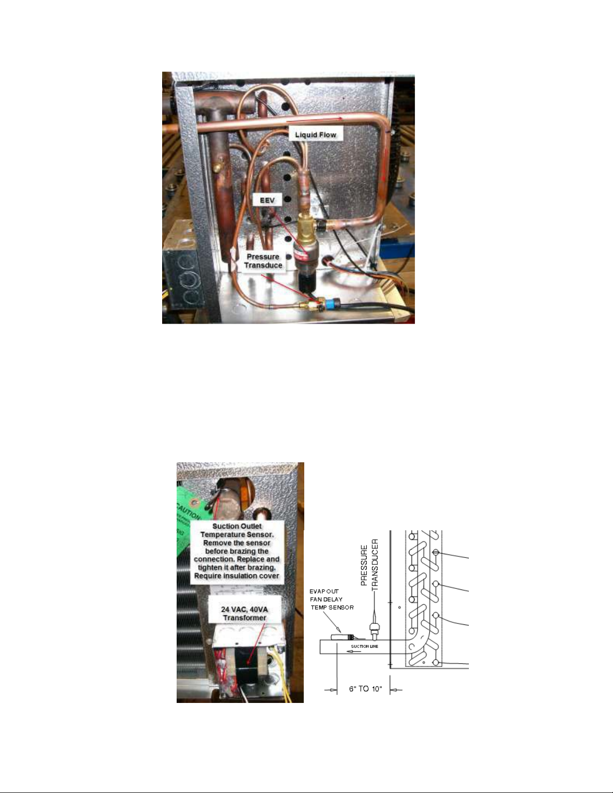
Picture 7
Picture 7 shows how and where the electric expansion valve and the pressure
transducer are mounted. The suction pressure transducer is seen on the
balanced tube in the picture but it can be also mounted on the service Schrader
port as shown in Picture 8.
The 24VAC transformer and the suction outlet temperature sensor are mounted
as shown in Picture 8.
Picture 8
Page 11

Master
-
Bilt Electronic Superheat Controller Bulletin
Page 11
The controller can be mounted inside the end plate as show in Picture 9 or on the
back side of the evaporator front panel as show in Picture 10.
Picture 9 Picture 10
Following are the procedures for field retrofit application:
1.
Power down the system
2.
Reclaim refrigerant
3.
Remove TEV,
4.
install EEV, Connect the liquid line to EEV side port
5.
Install pressure sensor
6.
Install temperature sensor
7.
Install Simple Superheat board, mounting screws provided
8.
Install 24 vac supply
9.
Wire board
10.
Set board (Remove Jumper CN4 for Low Temp Application)
11.
Disable head pressure control valve
12.
Recharge system
13.
Start system
Typical System Wiring Diagrams
Picture 3 shows the superheat controller wiring diagram and Picture 6
shows a typical system drawing. In Picture 6, the liquid line solenoid valve should
be controlled by the temperature control of the refrigeration system. For
individual system wiring diagram, please consult factory or technical service.
Page 12

Master
-
Bilt Electronic Superheat Controller Bulletin
Page 12
Troubleshooting
1.
Ensure 1 or more LEDs are on. (See LED section above)
a.
b.
2.
To ensure correct voltage is being supplied to the valve
a.
b.
c.
3.
If red LED is on, or pressure reading is suspected as out of tolerance,
a.
b.
c.
4.
If amber LED is on, or temperature reading is suspected as out of
tolerance,
a.
b.
c.
d.
e.
Make sure 20 to 26.5 VAC or DC power is on and measured across
terminals labeled ‘24VAC’
If voltage is there, but no LEDs are on, replace board.
Cycle 24 V power to controller.
Immediately after turning power back on, measure 10 to 15 VAC,
not DC across terminals labeled ‘1a’ and ‘2a’
Also measure 10 to 15 VAC, not DC across terminals labeled ‘1b’
and ‘2b’
i.
If correct voltage is not present, turn off power and
disconnect valve leads from controller
ii.
Repeat steps a, b, c again
iii.
If correct voltage is not present, replace controller, else
replace valve
Check wiring of pressure transducer
i.
Red lead is connected to terminal labeled ‘+5 vdc’
ii.
Black lead is connected to terminal labeled ‘Gnd’
iii.
White lead is connected to terminal labeled ‘Pres’
DC voltage measured across terminals labeled ‘+5 vdc’ and ‘Gnd’
should be 4.8 to 5.2 VDC.
i.
If correct voltage is not present, disconnect pressure
transducer from controller
ii.
Remeasure voltage as in step 3.a
iii.
If correct voltage is still not present, board is bad
iv.
If correct voltage is present, pressure transducer is bad or
cable is bad
Measure DC voltage across terminals labeled ‘Pres’ and ‘Gnd’
i.
Pressure = Measured dc voltage – 0.887) x 37.5
1.
Ie: if measured voltage is 1.5 VDC, pres = (1.5 .887)*37.5=22.9875 psig
ii.
Compare calculated pressure from voltage reading to
reading taken from external gauge. If the comparison is not
within 5 psig, replace pressure transducer
iii.
If pressure transducer measures OK, but red LED is on or
pressure reading is still suspected as bad, replace controller
Disconnect temperature sensor from controller
Measure resistance across leads of temperature sensor
Find temperature from temperature/resistance chart below
Compare temperature to temperature read from external source
If comparison is not within 5 deg F, replace sensor
Page 13
Master
-
Bilt Electronic Superheat Controller Bulletin
Page 13
-5
50
0
55
5
60
10
65
15
70
20
75
25
80
30
82
35
85
40
90
45
95
1
4
1
1
1
4
4
4
1
f.
If Temperature measures OK, but red LED is on or temperature
reading is still suspected as bad, replace controller
Deg F
Resistance Deg F
-60
-55
-50
-45
-40
-35
-30
-25
-20
-15
-10
58820
50653
43451
37407
32310
27957
24267
21127
18432
16117
14130
Resistance Deg F Resistance Deg F Resistance
12421
10941
9651
8544
7579
6731
5993
5349
4781
4281
3841
3454
3109
2805
2535
2294
2079
1888
1817
1716
1562
1424
100
105
110
115
120
125
130
135
140
145
150
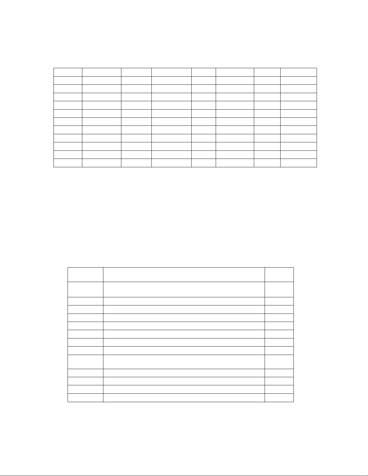
Ordering Information
Use the assembly kit number A900-22007 to order all parts required for field
retrofit.
A900-22007 Master-Bilt® Refrigeration Superheat Controller Kit
Assembly, 120/208/240/1/60, R404A, LT/MT APPS
A900-22007 contains the following parts:
Part
Number
19-13772
19-13967 NTC thermistor assembly, 30" long
19-14099 1/2" LONG ROUND PLASTIC SPACER
19-14221 Self-contained Superheat Controller board with
19-14223 Pressure transducer, Lead 16", 0 to 150 psia,
29-01695 Clear polycarbon window plug
39-01088
43-13214 #4-40 x 1" Pan Head PHIL ZINC
43-13215 #4-40 HEX NUT ZINC
43-13216 #4 Flat Washer ZINC
57-02155 Application and Installation Instructions for A900-22007
Description
Electric expansion valve SER-6, 1/2" ODF x 1/2" ODF
conformal coating and screw down terminal blocks
Green Signal, RED +5VDC, Black Ground
Transformer, 40VA, 120/208/240V Primary, 24VAC
Output
Quantity
1
1
1301
1189
1090
997
917
841
775
714
659
609
562
Page 14

Master
-
Bilt Electronic Superheat Controller Bulletin
Page 14
Please contact Master-Bilt Sales Department or Customer Service for ordering
replacement parts.
If there’s any question, please call Master-Bilt technical service department @
Master-Bilt Products
Technical Service Department
Highway 15 North
New Albany, MS 38652
Phone: 800-684-8988
Fax: 800-684-8988
Email: service@master-bilt.com
 Loading...