

Page 1

1
PREP TABLES
Installation, Operation and Maintenance Instructions
INSPECTION
When the equipment is received, all items should be carefully checked against the Bill
of Lading to insure all crates and cartons have been received. Do not sign the freight
bill clear until the freight has been properly inspected for damage. All units should be
inspected for damage including concealed damage by uncrating immediately. If any
damage is found, it should be reported to the carrier at once, noted on the Bill of Lading
and a claim should be filed with the carrier. This equipment has been inspected and
tested in the manufacturing facility and has been crated in accordance with
transportation rules and guidelines. The manufacturer is not responsible for freight loss
or damages.
INSTALLATION
The exterior of the cabinet and doors have been protected by a plastic covering. Peel
this protective covering before installation. After removing the covering, clean the
interior and exterior surfaces of the unit with soap and water and a rinse with clean
water. Do not use chlorinated cleaners on the surfaces as they can cause corrosion.
If the door(s) have come out of alignment during shipping they will need to be adjusted.
This can be accomplished by opening the door(s) and loosening the screws that hold
both the top and bottom hinges to the cabinet. After adjusting the door so it is aligned
correct, tighten the screws to securely hold the hinges and door(s ) in place.
The shelves and self clips are packaged inside the unit. Install the shelf clips on the
pilasters inside the unit and set the shelves on the clips. The shelves are adjustable in
½” increments. One (1) shelf can support up to 132 lbs (60kg).
The refrigeration system located in the rear of the unit requires free air access for
proper operation. Allow a minimum of seven inches between the back of the cabinet
and the wall. Do not locate the unit next to heat generating equipment or in direct
sunlight.
Confirm that the proposed electrical outlet has the correct voltage, frequency and
current carrying capacity for the requirements of the unit. This information is noted on
the data plate on the inside left wall of the unit. The unit should be isolated on a circuit.
Do not use an extension cord to get power to the unit. Improper electrical installations
will void the compressor warranty. To prevent shock and fire, be sure the unit is properly
grounded.
The temperature controller is located at the right front corner of the ceiling. The default
temperature is set at “4”. Adjust the temperature to fit your needs.
08/13 Rev. C 143492
Page 2
2
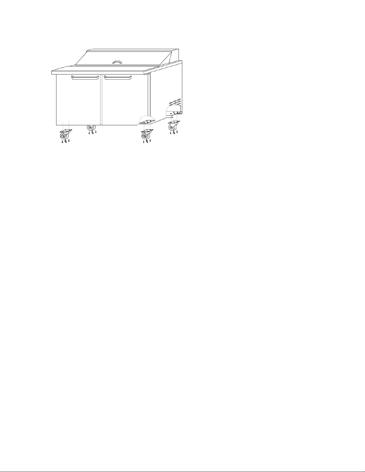
Install casters per the following diagram.
Note: Install casters with brakes to the front of the prep table.
MAINTENANCE
General Cleaning
Beginning with the initial installation, the interior surfaces of the cabinet should be
periodically cleaned with a solution of warm water and baking soda. This solution will
remove any odors from spillage that has occurred. The exterior of the cabinet should
also be cleaned frequently with a commercial stainless steel cleaner, glass cleaner or
mild soap solution. Do not use chlorinated cleaners on the stainless steel surfaces.
The door gaskets should be cleaned in place with a mild soap solution to extend their
life.
The shelving can be cleaned in a sink with a mild soap solution and a soft bristled
brush.
Condenser Coil Cleaning
Prior to cleaning the condenser coil disconnect the unit from power. Periodic cleaning of
the condenser coil will aid the heat transfer of the refrigeration system and increase its
efficiency. To accomplish this, remove the rear grill from the cabinet. The condenser
coil is located behind the grill. Use a soft bristled brush to remove any dirt particles that
are on the fins of the condenser coil. Use a vacuum cleaner or compressed air to
remove the loosened particles. Replace the grill and reconnect the unit to power.
Failure to clean the condenser coil can lead to performance loss and compressor
failure.
Stocking
When loading the cabinet with contents, do not block the fans in the ba ck. Blocking the
air flow may decrease performance.
08/13 Rev. C 143492
Page 3

3
TROUBLESHOOTING
Problem Remedy
· Check the power cord and make sure it is plugged in.
Compressor will
not start
Poor
performance
· Check the temperature controller. If it is in the “OFF” position,
turn it clockwise to set a desired temperature.
· Move the unit from direct sunlight.
· Move the unit away from heating devices.
· Install the unit in a well ventilated place,
with at least 7 inches of clearance on all sides.
· Clean the condenser if heavy dust is collected.
· Clear contents from bloc ki ng the air duct.
· Check the temperature controller for incorrect setting.
· Check the refrigerant level, it may need to be charged.
· Check the door and be sure it is completely closed.
Unit noisy
Condensation on
cabinet exterior
and/or floor
· Install the unit on a level surface.
· Maintain 7 inches of clearance from the wall.
· Check for loose part or mounting.
· Keep the tubing free from any contact to avoid rattle.
· Reduce humidity wher e the unit is installed.
· Repair or replace the gasket on the door.
08/13 Rev. C 143492
Page 4

4
SPECIFICATIONS
(170 L)
(282 L)
(368 L)
(453 liter)
(566 liter)
(170 L)
(283 L)
(368)
(453 L)
(566 L)
Range of
Temperature
PRODUCT STANDARD TOP PREP TABLES MEGA TOP PREP TABLES
Model SP27-8 SP36-10 SP48-12 SP60-16 SP72-18 SMP27-8 SMP36-10 SMP48-12 SMP60-16 SMP72-18
Capacity
Exterior
Dimensions
(including
casters)
Doors 1 Swing 2 Swing 2 Swing 2 Swing 3 Swing 1 Swing 2 Swing 2 Swing 2 Swing 3 Swing
Shelves 1 2 2 2 3 1 2 2 2 3
Pan Quantity 8 10 12 16 18 8 15 12 16 18
Compressor 1/5 HP 1/5 HP 3/8 HP 3/8 HP 3/8 HP 1/5 HP 1/5 HP 3/8 HP 3/8 HP 3/8 HP
Power Voltage 115V / 60Hz
Plug-In Installation NEMA 5-15P
Amps 3.2 3.4 7.9 7.9 8.1 3.2 3.4 7.9 7.9 8.1
Refrigerant R-134a
Net Weight (lbs) 198 250 284 316 348 198 254 284 316 348
7 CuFt
(W) 27.5” 36.1” 48.2” 60.4” 72.4” 27.5” 36.4” 48.2” 60.4” 72.4”
(D) 30.0” 33.1”
(H)* 42.5” 44.1”
10 CuFt
13 CuFt
16 CuFt
20 CuFt
+32°F ~ +40°F
7 CuFt
10 CuFt
13 CuFt
16 CuFt
20 CuFt
- Above specifications are subjected to change without prior notice for quality
improvement.
* Includes 6 inch casters. 3 inch casters are available.
08/13 Rev. C 143492
 Loading...