

Page 1
Installation & Operations Manual for
QMVM-L SERIES
Open Display Merchandisers
PN 57-01436
Rev 5-24-11
Page 2

2
TABLE OF CONTENT
INTRODUCTION………………………………….……………………………………………………………………3
STORE CONDITIONS / LOCATION ………….……………….…..………………………………………………. 3
WARNING LABELS AND SAFETY INSTRUCTIONS………..…..……………………………………………….4
PRE-INSTALLATION INSTRUCTIONS………………………..…..………………………………….…………… 4
Inspection for Shipping Damage……………………………………………………………….…………. ..4
INSTALLATION INSTRUCTIONS………………………………………………………………………………….. 5
General Instructions…………………………………………………………………………………………. 5
Thermometer Installation…………………………………………………………………………………… 5
Location………………………………………………………………………………………………………..5
Plumbing……………………………………………………………………………………………………….5
ELECTRICAL……..…………………………………………………………………………..……….……………….6
STARTING PROCEDURE…………………………………………………………………………………………….6
FINAL CHECK LIST…………………………………………………………………………………….……………..6
LOADING………………………………………………………………………………………………………………..7
PLACING PRODUCT IN CABINET ………………………………………………………………………………….7
CLEANING………………………………………………………………………………………………………………7
ELECTRONIC TEMPERATURE CONTROL ……………………………………………………………………….8
Fan……………………..……………………………………………………………………………………….8
Defrost…………………………………………………………… …………………………………………….8
Manual Defrost ……………………………………………………………………………………………….8
Setpoint.……………………………………………………………………………………………………….8
List Of Parameters……………………………………………………………………………………………9
How to change parameters…………………………………………………………………………………9
Alarm Buzzer and Signals..…………………………………………………………………………………9
ELECTRICAL CONNECTIONS……………………………………………………………………………… ..……...10
PROBE CONNECTIONS…………………………………………………………………………………… ..………..10
SENSOR PROBE TEMPERATURE AND RESISTANCE………………………………………………..………...10
SERVICE INSTRUCTIONS (Trouble Shooting Guide)………………………………………………… ..……….11
MASTER-BILT PART NUMBERS………………………………………………………………………… ..………..12
ACCESSORIES LIST……………………………………………………………………………………… ..…………13
SALE AND DISPOSAL…………………………………………………………………………………… ..……….…13
QMVM-36L, 48L WIRINGDIAGRAM ………………………………………….…………………………....……14-15
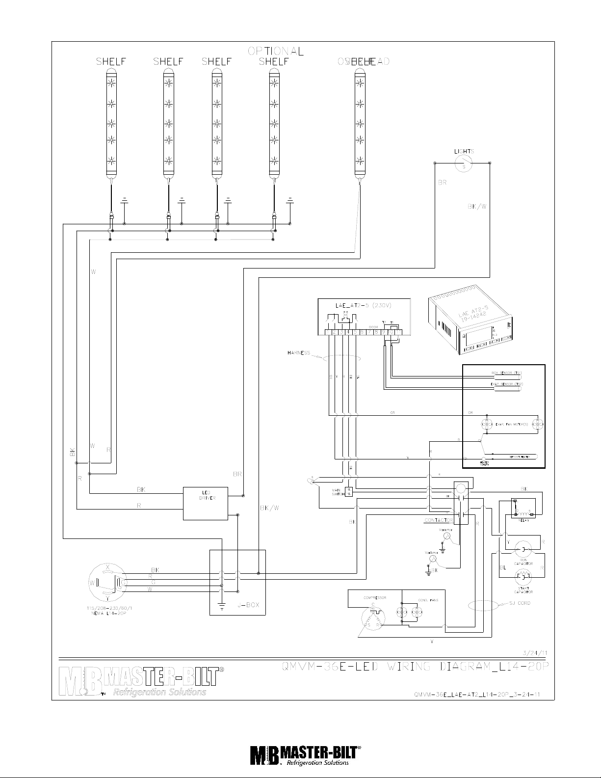
QMVM-36E WIRING DIAGRAM……………………..……………………………….…………..….….….……..16-17
QMVM-48E WIRING DIAGRAM…………………………..…………………………….…………………………18-19
QMVM-72E WIRINGDIAGRAM……………………….………….…………………………………….…….……20-21
Page 3
3
INTRODUCTION
Thank you for purchasing a Master-Bilt cabinet. This manual contains important instructions for installing, using and
servicing a Master-Bilt QMVM series open air case. Read all these documents carefully before installing or servicing
your equipment. This manual should be left in the care of the store owner or manager.
STORE CONDITIONS / LOCATION
The Master-Bilt QMVM cases are designed to operate in the controlled environment of an air conditioned store. The
store temperature should be at or below 75°F and a relative humidity of 55% or less. At higher temperature or
humidity conditions, the performance of these cases may be affected and the capacity diminished. It is not
uncommon in a newly constructed store for the temperature and humidity to be above design conditions. These
excessive conditions may produce sweating in the case until the store is operational and the ambient environment is
more desirable.
The Master-Bilt QMVM should not be positioned where it is directly exposed to rays of the sun or near a direct source
of radiant heat or air flow. No HVAC return or supply air ducts may be located near case openings. This will adversely
affect the case air flow and will result in poor performance. Do not open windows or doors that will affect the case air
flow. The maximum air velocity near the case air return is 50 FPM. If this case is to be located against a wall there
should be at least a 6” space between the wall and the back of the case. The cabinet also requires a clearance of 10”
at the top. This space will allow for the circulation of air behind the case.
These cases should always be loaded properly. This unit will operate differently when loaded or unloaded. Consult
the section of this manual that specifies loading procedures on page 6.
A P-trap is included with each case. It is important that each case has a P -trap installed. Consult the section of this
manual for installing and piping the drain.
NOTICE
Read this manual before installing your cabinet. Keep the manual and refer to it before
doing any service on the equipment. Failure to do so could result in personal injury or damage to the
cabinet.
DANGER
Improper or faulty hook-up of electrical components of the refrigeration units can result in
severe injury or death.
All electrical wiring hook-ups must be done in accordance with all applicable local, regional or national
standards.
NOTICE
Installation and service of the refrigeration and electrical components of the cabinet must be performed by a
refrigeration mechanic and/or a licensed electrician.
The portion of this manual covering refrigeration and electrical components contain technical instructions intended
only for persons qualified to perform refrigeration and electrical work.
This manual cannot cover every installation, use or service situation. If you need additional information, call or write
us:
Customer Service Department
Master-Bilt Products
Highway 15 North
New Albany, MS 38652
Phone (800) 684-8988
Fax (800) 684-8988
Page 4
4
CAUTION!
GROUND REQUIRED
FOR SAFE OPERATION
WARNING LABELS AND SAFETY INSTRUCTIONS
This symbol is the safety-alert symbol. When you see this symbol on your cabinet or in this
manual, be alert to the potential for personal injury or damage to your equipment.
Be sure you understand all safety messages and always follow recommended precautions
and safe operating practices.
NOTICE TO EMPLOYERS
You must make sure that everyone who installs, uses or services your cabinet is thoroughly familiar with all
safety information and procedures.
Important safety information is presented in this section and throughout this section and throughout the manual. The
following signal words are used in the warnings and safety messages:
DANGER: Severe injury or death will occur if you ignore the message.
WARNING: Severe injury or death can occur if you ignore the message.
CAUTION: Minor injury or damage to your cabinet can occur if you ignore the message.
NOTICE: This is important installation, operation or service information. If you ignore the
message, you may damage your cabinet.
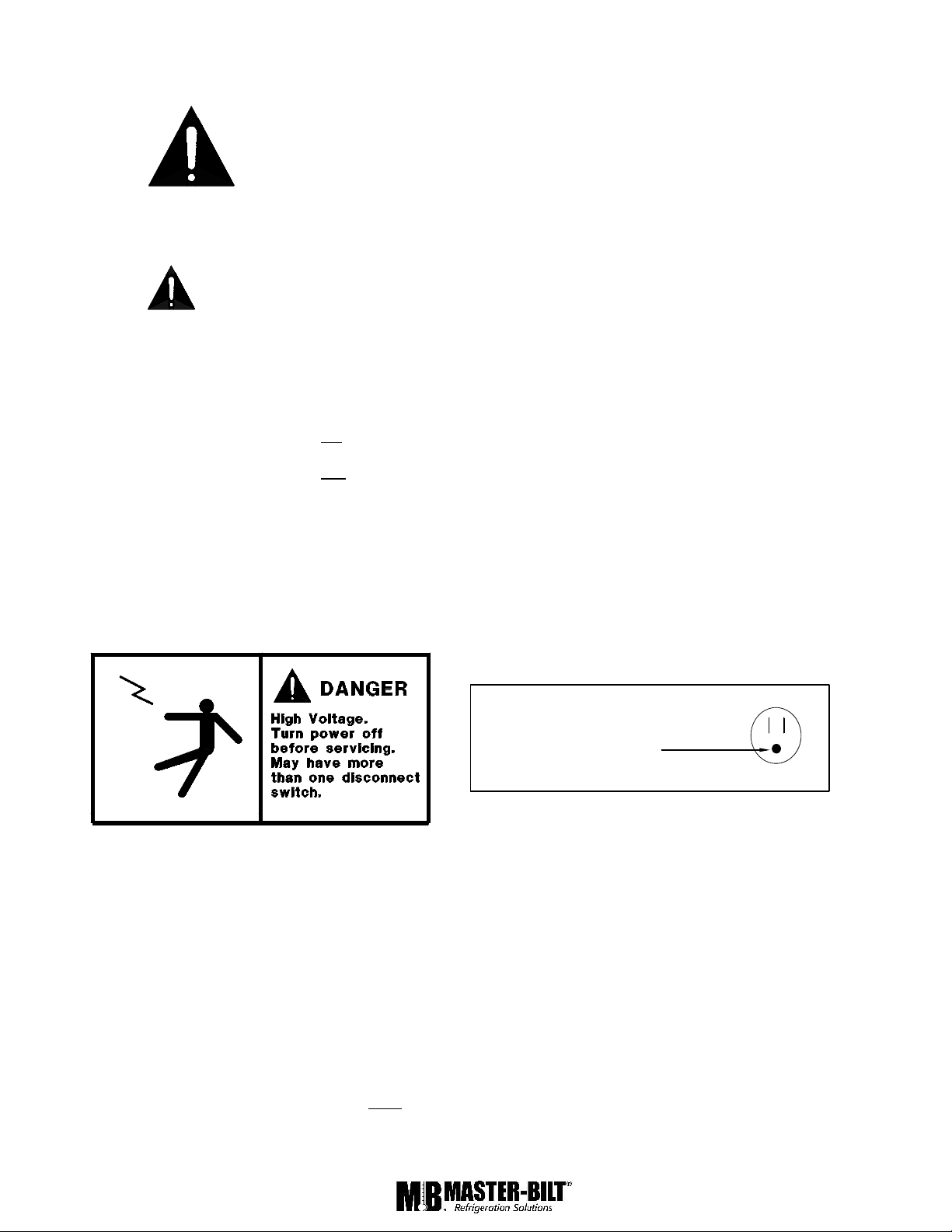
The warning and safety labels shown throughout this manual are placed on your Master -Bilt Products
cabinet at the factory. Follow all warning label instructions. If any warning or safety labels become lost or
damaged, call your customer service department at (662) 534-9061 for replacements.
This label is located on the electrical control This label is attached to the cabinet power cord on
box and on the rear access cover. models with a power cord.
PRE-INSTALLATION INSTRUCTIONS
INSPECTION FOR SHIPPING DAMAGE
You are responsible for filing all freight claims with the delivering truck line. Inspect all cartons and crates for damage
as soon as they arrive. If damage is noted to shipping crates or cartons or if a shortage is found, note this on the bill
of lading (all copies) prior to signing.
If damage is discovered when the cabinet is uncrated, immediately call the delivering truck line and follow up the call
with a written report indicating concealed damage to your shipment. Ask for an immediate inspection of your
concealed damage item. Crating material must be retained to show the inspector from the truck line.
Page 5
5
INSTALLATION INSTRUCTIONS
GENERAL INSTRUCTIONS
1. Be sure the equipment is properly installed by competent service people.
2. Keep the equipment clean and sanitary so it will meet your local sanitation codes. Wipe up all spills, clean with
water and a mild detergent, then rinse with clean water. A reservoir is provided to contain inner spills. Peridocially
inspect reservoir and clean as needed.
3. Rotate your stock so that older stock does not accumulate. A "First-In, First-Out" rotation practice will keep the
products in good salable condition.
4. Product should not be put in the case for at least 2 hours after it is started.
5. Stock cases as quickly as possible, exposing only small quantities to store temperatures for short periods of time.
6. When replacing burned out fluorescent tubes, be sure that the electrical power to the lighting circuit is turned off.
INSTALLATION INSTRUCTIONS
To comply with Sanitation requirements, this cabinet must be mounted on casters, legs (6” high min.) or the base
must be sealed to the floor with NSF listed silicone sealant. Minimum clearance as follows: 10” air space at top, 6” at
the rear, and 0” air space at each side required for compliance.
Before moving cabinet into place, route cabinet plumbing with P-trap to store drain line or install optional condensate
pan.
THERMOMETER INSTALLATION
Install provided thermometer at the clip on the price tag moulding near the top left edge of the case. Remove the tape
backing and press the thermometer in place.
PLUMBING
Each QMVM case has a P-trap installed. It is very important that this trap not be removed as it will result in
diminished peformance of the case without it.
1. Always install drains in accordance with local codes.
2. Use largest possible size pipe for drains, ¾” minimum is recommended.
3. Provide as much downhill slope as possible.
4. Prevent drains from freezing. Do not install drains in contact with uninsulated suction lines.
NOTICE TO STORE OWNERS / MANAGERS
Moisture or liquid around or under the cabinet is a potential slip/fall hazard for persons walking by or
working in the general area of the cabinet. Any cabinet malfunction or housekeeping problem that creates a
slip/fall hazard around or under the cabinet should be corrected immediately.
If moisture or liquid is observed around or under a Master-Bilt cabinet, an immediate investigation should be made by
qualified personnel to determine the source of the moisture or liquid. The investigation made should determine if the
cabinet is malfunctioning or if there is a drain pipe leaking.
Page 6

6
ELECTRICAL
WARNING
Before servicing electrical components in the case make sure all power to case is off. Always use a qualified
technician.
STARTING PROCEDURE
1. Start compressor and allow the case to pull down to 42 degrees or below before placing product into the
QMVM.
DURING THIS TESTING PERIOD YOU SHOULD:
1. Check that the compressor cycles off and back on at least once.
FINAL CHECK LIST
A. Check that the evaporator drain line is properly connected.
B. All shelves are properly installed.
B. Check electrical supply voltage to make sure it is in range.
C. All loose items and debris is removed from inside of unit and lower equipement compartment.
D. Check condensing unit for vibrating or rubbing tubing. Dampen and clamp as required.
E. All valves should be completely open counter-clockwise.
F. Check packing nuts on all service valves.
G. Replace all service valve caps and latch unit covers.
I. Check that the temperature of the case is between 35 and 42 degrees.
Page 7
7
LOADING
Do not place product in the case until 2 hours after it
is started. Stock cases as quickly as possible,
exposing only small quantities to store temperatures
for short periods of time. It is important to keep stock
rotated properly so that older stock does not
accumulate. A “First-In, First-Out” rotation practice
will keep the products in good salable condition.
Avoid loading the case so that product sticks out
beyond the shelves or blocking the return air grille at
the bottom of the case. This will interfere with the air
flow of the case and will result in diminished
performance.
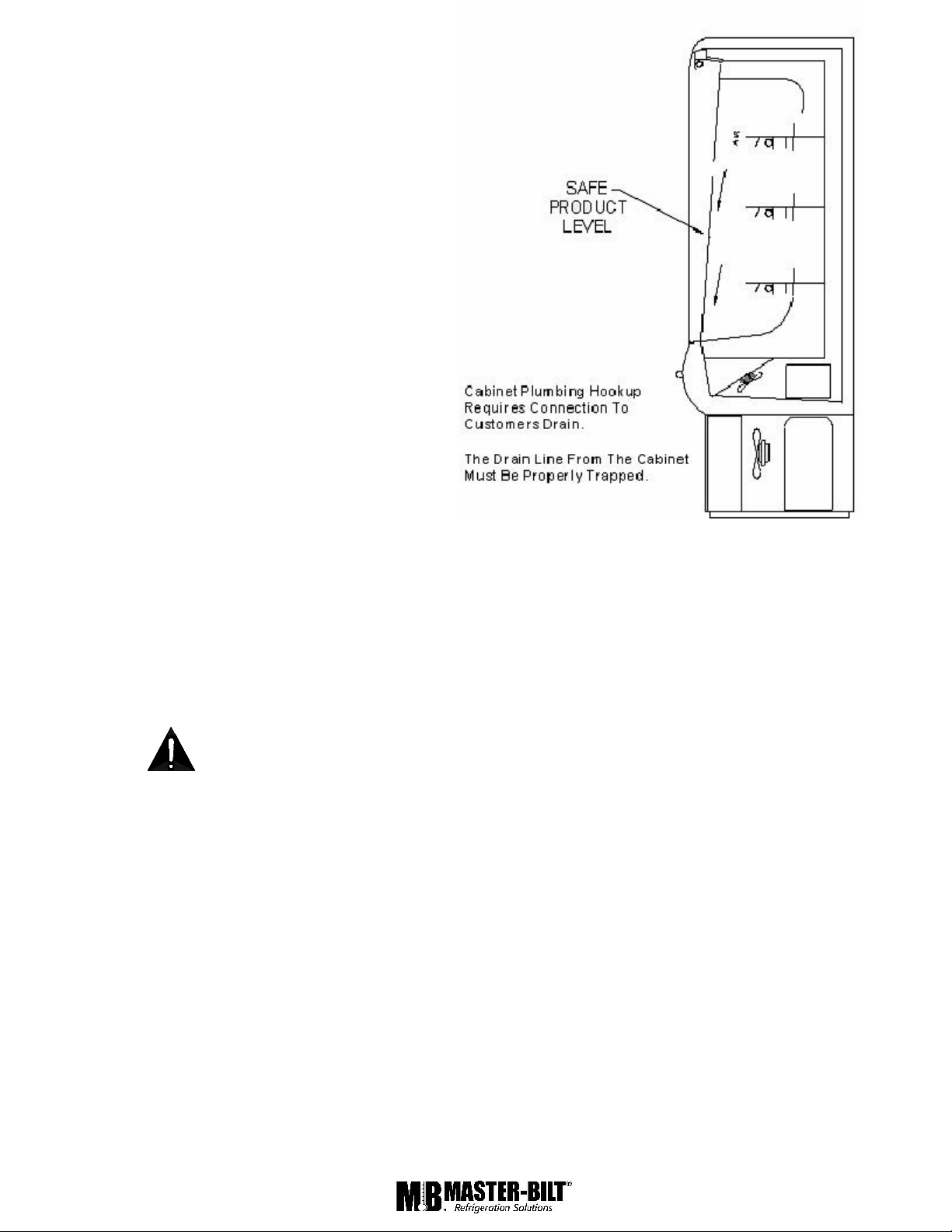
PLACING PRODUCT IN THE CABINET
Do not load the cabinet with product to the point that the air discharge grille, air intake grille, or the air curtain created
by the discharge air, is blocked. The following diagram shows proper loading.
All units come with 14” shelves sufficient to have 3 levels.
CLEANING
To avoid electrical shock, turn the power off before cleaning.
The QMVM series cabinets are designed so that spills will accumulate in a drain pan. The drain pan is located
underneath the return air grill. Be sure to clean all areas with a mild detergent and water periodically.
Page 8

8
MASTER-BILT ELECTRONIC REFRIGERATION CONTROL
Display Lay -out
Compressor When power is first turned on to the control, the LED indicator under COMP on the display starts
blinking. After one-minute delay the compressor comes on. The LED indicator stays on while compressor relay is
energized. Display will show actual box temperature. Picture above is the display layout. The compressor will be
cycled off when the actual box temperature reaches its set point. The COMP indicator will be off.
Fan The fans will run constantly during cool mode and defrost mode, or when the evaporator temp is above 55oF.
FAN LED indicator is on while FAN relay is energized.
Defrost The control uses time defrost with 6 defrost per day. The defrost scheme can be re-set the for special
applications. During defrost the display will show dEF and the defrost LED indicator on. The control begins timing the
defrost when power is turned on. Four defrost per day means it will occur every 4 hours.
MANUAL DEFROST
Defrosting my also be induced manually by keeping the defrost button for 3 seconds. Once defrost has started, the
defrost will go through a defrost and drip time pull down cycle.
Page 9

9
HOW TO CHANGE THE SETPOINT
HOW TO CHANGE a parameter value
LIST OF PARAMETERS
Here is a list of the parameters the value of which can be changed in the programming mode, as well as their ranges.
Display
Symbol
Parameter
Range
Master-Bilt’s
Setting
SP
Temperature Set Point
SPL…SPH
30°F
HYS
Temperature Differential
1 to 255°F
5°
SPL
Minimum Temperature limit setpoint
-50…SPH
27°F
SPH
Maximum Temperature limit setpoint
SPH…120°
55°F
AHA
High Temperature alarm
-50…120°
60°F
ALA
Low Temperature Alarm
50…120°
0F
ATD
Temperature Alarm Delay
0…120min
30min
DFR
Number of Defrost Cycle per 24hr
0…24
6/day
DLI
Defrost Termination Temperature
-50…120°
55°F
DTO
Maximum Defrost Duration
1…120min
30min
ELECTRICAL CONNECTIONS
The controller is provided with screw/push terminal block to connect cables with a cross section up to 2,5 mm2. Before
connecting cables make sure the power supply complies with the control’s requirements. Separate the probe cables
from the power supply cables, from the outputs and the power connections. Do not exceed the maximum current
allowed on each relay, in case of heavier loads use a suitable external relay or contactor’s.
PROBE CONNECTIONS
The probes shall be mounted with the bulb upwards to prevent damages due to casual liquid infiltration. It is
recommended to place the thermostat probe away from air streams to correctly measure the average room
temperature. Place the defrost termination probe among the evaporator fins in the coldest place, where most ice is
formed, far from heaters or from the warmest place during defrost, to prevent premature defro st termination.
Page 10

10
SENSOR PROBE TEMPERATURE AND RESISTANCE
NTC10K Temperature-Resistance
Temp (ºC)
Temp (ºF)
R-low (Kohm)
R-center (Kohm)
R-high (Kohm)
-40
-40
188.021
195.652
203.573
-35
-31
142.788
148.171
153.741
-30
-22
109.522
113.347
117.294
-25
-13
84.823
87.559
90.374
-20-466.270
68.237
70.255
-15552.229
53.650
55.104
-101441.477
42.506
43.557
-52333.147
33.892
34.651
03226.678
27.219
27.767
54121.630
22.021
22.417
105017.643
17.926
18.210
155914.472
14.674
14.877
206811.938
12.081
12.224
25779.900
10.000
10.100
30868.217
8.315
8.413
35956.854
6.948
7.043
40
104
5.745
5.834
5.923
45
113
4.834
4.917
5.001
50
122
4.084
4.161
4.239
55
131
3.464
3.535
3.607
60
140
2.949
3.014
3.081
65
149
2.526
2.586
2.647
70
158
2.173
2.228
2.283
75
167
1.875
1.925
1.976
80
176
1.623
1.669
1.715
85
185
1.411
1.452
1.495
90
194
1.230
1.268
1.307
95
203
1.075
1.110
1.145
100
212
0.942
0.974
1.006
105
221
0.829
0.858
0.888
110
230
0.732
0.758
0.785
115
239
0.647
0.671
0.696
120
248
0.574
0.596
0.619
125
257
0.511
0.531
0.552
Page 11

11
SERVICE INSTRUCTIONS (Trouble Shooting Guide)
1. High head pressure and high back pressure:
A. Condenser coil clogged or restricted.
B. Condenser fan motor defective.
2. Low back pressure and low head pressure:
A. Restriction in system.
B. Refrigerant undercharged.
C. Leak in system.
3. Pressures normal – cabinet warm:
A. Coil blocked with frost or ice (see #4).
B. Control set too warm.
C. Air screen disturbance.
4. Coil blocked with frost or ice:
A. Defective temperature contro
B. Defective or disconnected coil sensor.
C. Improper control setting.
D. Defrost heater not operating.
E. Ambient conditions above 75 F/55
F. P-trap in train not installed.
G. Evaporator fan motor defective.
H. Air screen disturbance.
5. Compressor starts and runs – but cycles on overload:
A. Low voltage.
B. Dropped phase (3 phase).
C. Overload protector defective.
D. High head pressure (see#1).
E. Relay or Capacitor defective.
6. Compressor will not start – hums, but cycles on overload.
A. Low voltage.
B. Relay defective.
C. Overload protector defective.
D. Start capacitor defective.
E. High head pressure (see #1)
Page 12

MASTER-BILT PART NUMBERS
Description
QMVM-36E
QMVM-48E
QMVM-72E
Shelves and overhead Ballast
23-01709
23-01709
23-01704
Compressor
03-14494
03-14762
03-14480
Condenser Coil
07-13226
07-13195
07-13197
Condenser Fan Blade
15-13097
15-13081
15-13090
Condenser Fan Motor
13-01283
13-13121
13-13121
Contactor
N/A
19-00792
19-00792
Defrost Heater
17-09251
17-09205
17-09206
Thermometer
44-01033
44-01033
44-01033
Drier
09-09506
09-09506
09-09506
Evaporator Coil
07-13225
07-13188
07-13186
Evaporator Fan Blade
15-13106
15-13084
15-13084
Evaporator Fan Motor
13-13114
13-13114
13-13114
Expansion Valve
09-09553
09-09553
09-09553
Female Plug
21-00568
21-00568
21-00568
Flourecent Lamp, 18”
23-00329
23-00329
Flourecent Lamp, 24”
23-01507
Flourecent Lamp, 36”
23-00325
Flourecent Lamp, 60”
23-00360
Front Glass
31-02270
54-01434
54-01435
Heater Safety Switch
19-01307
19-01307
19-01307
Lampholder
23-50562
23-01128
23-50562?
Light Switch
19-01071
19-01071
19-01071
Receiver Tank
N/A
09-01162
09-01162
Refrigerant
30 oz.(404A)
88 oz.(404A)
102oz.(404)
Shelf Power Cord
21-01278
21-01278
21-01278
Electronic Controller
19-14242
19-14242
19-14242
Box Sensor T1
19-14244
19-14244
19-14244
Evaporator Sensor T2
19-14245
19-14245
19-14245
The table below gives Master-Bilt part numbers. Use this chart when ordering replacement parts for your QMVM
cases.
All quantities are one each unless otherwise noted by parentheses.
12
Page 13

ACCESSORIES LIST
Description
QMVM-36
QMVM-48
QMVM-72
Extra Shelves
14” Lighted Shelf (White)
A068HW214
A075HW214
A076HW214
14” Non-Lighted Shelf (White)
A068DW114
A075DW114
A076DW114
14” Lighted Shelf (Black)
A068HB214
A075HB214
A076HB214
14” Non-Lighted Shelf (Black)
A068DB114
A075DB114
A076DB114
14” Lighted Shelf (Stucco Black)
A068HP214
A075HP214
A076HP214
14” Non-Lighted Shelf (Stucco Black)
A068HP114
A075HP114
A076HP114
14” Lighted Shelf (Seville White)
A068HQ214
A075HQ214
A076HQ214
14” Non-Lighted Shelf (Seville White)
A068HQ114
A075HQ114
A076HQ114
14” Lighted Shelf (Seville Black)
A068HR214
A075HR214
A076HR214
14” Non-Lighted Shelf (Seville Black)
A068HR114
A075HR114
A076HR114
Product Hook Assembly
bar, shelf brackets, 6” hooks
A068-15000
A075-15000
A076-15000
6” extra hooks
44-01016
44-01016
44-01016
Condensate Evaporator Drain Pan
17-09287
17-09264
17-09264
Condensate Pump
61-00529
Casters
Set of four, 3” diameter
A075-11140
A075-11140
Set of six, 3” diameter
A076-11140
SALE AND DISPOSAL
OWNER RESPONSIBILITY
If you sell or give away your Master-Bilt cabinet you must make sure that all safety labels and the Installation - Service
Manual are included with it. If you need replacement labels or manuals, Master-Bilt will provide them free. Contact
the customer service department at Master-Bilt at (800) 684-8988.
The customer service department at Master-Bilt should be contacted at the time of sale or disposal of your cabinet so
records may be kept of its new location.
If you sell or give away your Master-Bilt cabinet and you evacuate the refrigerant charge before shipment, Master-Bilt
recommends that the refrigerant charge be properly recovered in complience with section 608 of the Clean Air Act
effective November 1995 and in accordance with all applicable local, regional, or national standards.
13
Page 14

14151617181920
Page 15

Page 16

Page 17
Page 18

Page 19

Page 20

Page 21

21
 Loading...