

Page 1
Installation & Operations M a nual
Master-Bilt Products
908 Highway 15 North
New Albany, MS 38652
Phone: (800) 684-8988
By: LN
Rev: 08/08/2006
57-01436
1
Page 2

TABLE OF CONTENTS
INTRODUCTION………………………………….……………………………………………………………………3
STORE CONDITIONS / LOCATION ………….……………….…..………………………………………………. 3
WARNING LABELS AND SAFETY INSTRUCTIONS………..…..……………………………………………….4
PRE-INSTALLATION INSTRUCTIONS………………………..…..………………………………….…………… 4
Inspection for Shipping Damage……………………………………………………………….…………... 4
INSTALLATION INSTRUCTIONS………………………………………………………………………………….. 5
General Instructions…………………………………………………………………………………………. 5
Thermometer Installation…………………………………………………………………………………… 5
Location………………………………………………………………………………………………………..5
Plumbing……………………………………………………………………………………………………….5
Electrical……..…………………………………………………………………………..…………………….6
STARTING PROCEDURE…………………………………………………………………………………………….6
FINAL CHECK LIST…………………………………………………………………………………….……………..6
LOADING………………………………………………………………………………………………………………..6
OPERATING INSTRUCTIONS / TEMPERATURE CONTROL …………………………………………………..6
PLACING PRODUCT IN CABINET ………………………………………………………………………………….7
CLEANING………………………………………………………………………………………………………………8
PROGRAMMING……………………………………………………………………………………………………8-11
SERVICE INSTRUCTIONS…………………………………………………………………………………………..12
MASTER-BILT PART NUMBERS……………………………………………………………………………….12-13
ACCESSORIES LIST………………………………………………………………………………………………….14
SALE AND DISPOSAL…………………………………………………………………………………………….….14
WIRING DIAGRAMS………….…………………………………………………………….…………..…………15-21
.
2
Page 3
INTRODUCTION
Thank you for purchasing a Master-Bilt cabinet. This manual contains important instructions for installing, using and
servicing a Master-Bilt QMVM series open air case. Read all these documents carefully before installing or servicing
your equipment. This manual should be left in the care of the store owner or manager.
STORE CONDITIONS / LOCATION
The Master-Bilt QMVM cases are designed to operate in the controlled environment of an air conditioned store. The
store temperature should be at or below 75°F and a relative humidity of 55% or less. At higher temperature or humidity
conditions, the performance of these cases may be affected and the capacity diminished. It is not uncommon in a
newly constructed store for the temperature and humidity to be above design conditions. These excessive conditions
may produce sweating in the case until the store is operational and the ambient environment is more desirable.
The Master-Bilt QMVM should not be positioned where it is directly exposed to rays of the sun or near a direct source
of radiant heat or air flow. No HVAC return or supply air ducts may be located near case openings. This will adversely
affect the case air flow and will result in poor performance. Do not open windows or doors that will affect the case air
flow. The maximum air velocity near the case air return is 50 FPM. If this case is to be located against a wall there
should be at least a 6” space between the wall and the back of the case. The cabinet also requires a clearance of 10”
at the top. This space will allow for the circulation of air behind the case.
These cases should always be loaded properly. This unit will operate differently when loaded or unloaded. Consult the
section of this manual that specifies loading procedures on page 6.
A P-trap is included with each case. It is important that each case has a P-trap installed. Consult the section of this
manual for installing and piping the drain.
NOTICE
Read this manual before installing your cabinet. Keep the manual and refer to it before
doing any service on the equipment. Failure to do so could result in personal injury or damage to the cabinet.
DANGER
Improper or faulty hook-up of electrical components of the refrigeration units can result in
severe injury or death.
All electrical wiring hook-ups must be done in accordance with all applicable local, regional or national
standards.
NOTICE
Installation and service of the refrigeration and electrical components of the cabinet must be performed by a
refrigeration mechanic and/or a licensed electrician.
The portion of this manual covering refrigeration and electrical components contain technical instructions intended only
for persons qualified to perform refrigeration and electrical work.
This manual cannot cover every installation, use or service situation. If you need additional information, call or write us:
Customer Service Department
Master-Bilt Products
Highway 15 North
New Albany, MS 38652
Phone (800) 684-8988
Fax (800) 684-8988
3
Page 4
WARNING LABELS AND SAFETY INSTRUCTIONS
This symbol is the safety-alert symbol. When you see this symbol on your cabinet or in this
manual, be alert to the potential for personal injury or damage to your equipment.
Be sure you understand all safety messages and always follow recommended precautions
and safe operating practices.
NOTICE TO EMPLOYERS
You must make sure that everyone who installs, uses or services your cabinet is thoroughly familiar with all
safety information and procedures.
Important safety information is presented in this section and throughout this section and throughout the manual. The
following signal words are used in the warnings and safety messages:
DANGER: Severe injury or death will
WARNING: Severe injury or death can
CAUTION: Minor injury or damage to your cabinet can occur if you ignore the message.
NOTICE: This is important installation, operation or service information. If you ignore the
message, you may damage your cabinet.
The warning and safety labels shown throughout this manual are placed on your Master-Bilt Products cabinet
at the factory. Follow all warning label instructions. If any warning or safety labels become lost or damaged,
call your customer service department at (662) 534-9061 for replacements.
occur if you ignore the message.
occur if you ignore the message.
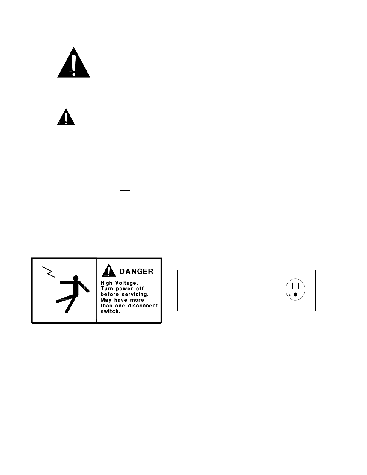
CAUTION!
GROUND REQUIRED
FOR SAFE OPERATION
This label is located on the electrical control This label is attached to the cabinet power cord on
box and on the rear access cover. models with a power cord.
PRE-INSTALLATION INSTRUCTIONS
INSPECTION FOR SHIPPING DAMAGE
You are responsible for filing all freight claims with the delivering truck line. Inspect all cartons and crates for damage
as soon as they arrive. If damage is noted to shipping crates or cartons or if a shortage is found, note this on the bill of
lading (all copies) prior to signing.
If damage is discovered when the cabinet is uncrated, immediately call the delivering truck line and follow up the call
with a written report indicating concealed damage to your shipment. Ask for an immediate inspection of your concealed
damage item. Crating material must
be retained to show the inspector from the truck line.
4
Page 5

INSTALLATION INSTRUCTIONS
GENERAL INSTRUCTIONS
1. Be sure the equipment is properly installed by competent service people.
2. Keep the equipment clean and sanitary so it will meet your local sanitation codes. Wipe up all spills, clean with
water and a mild detergent, then rinse with clean water. A reservoir is provided to contain inner spills. Peridocially
inspect reservoir and clean as needed.
3. Rotate your stock so that older stock does not accumulate. A "First-In, First-Out" rotation practice will keep the
products in good salable condition.
4. Product should not be put in the case for at least 2 hours after it is started.
5. Stock cases as quickly as possible, exposing only small quantities to store temperatures for short periods of time.
6. When replacing burned out fluorescent tubes, be sure that the electrical power to the lighting circuit is turned off.
INSTALLATION INSTRUCTIONS
To comply with Sanitation requirements, this cabinet must be mounted on casters, legs (6” high min.) or the base must
be sealed to the floor with NSF listed silicone sealant. Minimum clearance as follows: 10” air space at top, 6” at the
rear, and 0” air space at each side required for compliance.
Before moving cabinet into place, route cabinet plumbing with P-trap to store drain line or install optional condensate
pan.
THERMOME TER INSTALLATION
Install provided thermometer at the clip on the price tag moulding near the top left edge of the case. Remove the tape
backing and press the thermometer in place.
PLUMBING
Each QMVM case has a P-trap installed. It is very important that this trap not be removed as it will result in diminished
peformance of the case without it.
1. Always install drains in accordance with local codes.
2. Use largest possible size pipe for drains, ¾” minimum is recommended.
3. Provide as much downhill slope as possible.
4. Prevent drains from freezing. Do not install drains in contact with uninsulated suction lines.
NOTICE TO STORE OWNERS / MANAGERS
Moisture or liquid around or under the cabinet is a potential slip/fall hazard for persons walking by or working
in the general area of the cabinet. Any cabinet malfunction or housekeeping problem that creates a slip/fall
hazard around or under the cabinet should be corrected immediately.
If moisture or liquid is observed around or under a Master-Bilt cabinet, an immediate investigation should be made by
qualified personnel to determine the source of the moisture or liquid. The investigation made should determine if the
cabinet is malfunctioning or if there is a drain pipe leaking.
5
Page 6

ELECTRICAL
WARNING
Before servicing electrical components in the case make sure all power to case is off. Always use a qualified
technician.
STARTING PROCEDURE
1. Start compressor and allow the case to pull down to 42 degrees or below before placing product into the
QMVM.
DURING THIS TESTING PERIOD YOU SHOULD:
1. Check that the compressor cycles off and back on at least once.
FINAL CHECK LIST
A. Check that the evaporator drain line is properly connected.
B. All shelves are properly installed.
B. Check electrical supply voltage to make sure it is in range.
C. All loose items and debris is removed from inside of unit and lower equipement compartment.
D. Check condensing unit for vibrating or rubbing tubing. Dampen and clamp as required.
E. All valves should be completely open counter-clockwise.
F. Check packing nuts on all service valves.
G. Replace all service valve caps and latch unit covers.
I. Check that the temperature of the case is between 35 and 42 degrees.
LOADING
Do not place product in the case until 2 hours after it is started. Stock cases as quickly as possible, exposing only
small quantities to store temperatures for short periods of time. It is important to keep stock rotated properly so that
older stock does not accumulate. A “First-In, First-Out” rotation practice will keep the products in good salable
condition. Avoid loading the case so that product sticks out beyond the shelves or blocking the return air grille at the
bottom of the case. This will interfere with the air flow of the case and will result in diminished performance.
OPERATING INSTRUCTIONS / TEMPERATURE CONTROL
The refrigeration system is controlled by an ERC2 electronic control.
The factory setting will give an operating temperature of 38°F to 42°F. If a warmer or colder temperature is
desired, see the programming section of this manuel.
The case temperature sensor from the ERC2 control is positioned in the evaporator return air. The coil temperature
sensor from the ERC2 control is inserted in the coil about 1 inch from the left side as viewed when looking into the
cabinet, and about 2 inches from the top of the evaporator coil. The coil temperature sensor must be fully inserted into
the coil pack to approximately the middle of the coil. The ERC2 control is factory set to provide the proper operating
condition for most applications. If it is determined that the settings should be changed, then please see the
programming section. The ERC2 control is factory set to provide four defrosts per day. It is recommended that the
continuous evaporator fan operation as factory set be used for the best operation. The continuous fan operation will
allow the evaporator fan to run during the compressor off cycles and also during the defrost cycle.
6
Page 7
Overstocking the cabinet, or adverse operating
conditions, will have an effect on the cabinet and
product temperatures.
W
R
I
O
A
L
F
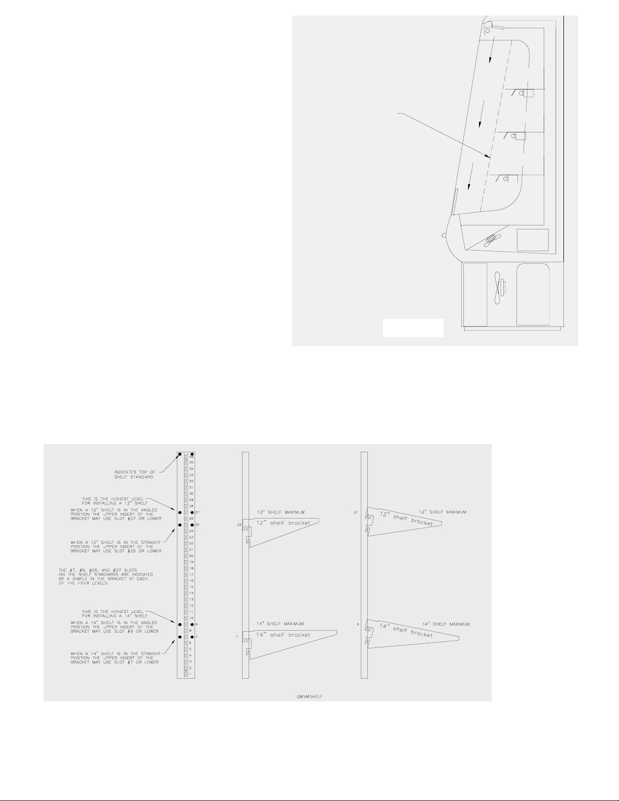
PLACING PRODUCT IN THE CABINET
Do not load the cabinet with product to the point that
the air discharge grille, air intake grille, or the air
SAFE
PRODUCT
LEVEL
curtain created by the discharge air, is blocked. The
following diagram shows proper loading.
There are three (3) shelves furnished as standard
with the QMVM cabinet: 10” shelf, 12” shelf and 14”
shelf. The 14” shelf MUST be the bottom shelf, and
the shelf bracket located so that the top insert of the
bracket is placed no higher thatn the No. 7 slot in the
shelf support when the shelf is installled in a
horizontal position. If the lower shelf is installed in
the angled down position, the top insert of the shelf
bracket may be as high as the No. 9 slot.
The 12” shelf is to be used as the middle shelf, and
Cabinet Plumbing Hookup
Requires Connection To
Customers Drain.
The Drain Line From The Cabinet
Must Be Properly Trapped.
the shelf bracket located so that the top insert of the
bracket is placed no higher than the No. 25 slot in the
shelf support when the shelf is installed in a
Figure 1.1
horizontal position. If the lower shelf is installed in
the angled down position, the top insert of the shelf bracket may be as high as the No. 27 slot.
The #7, #9, #25, and #27 slots are marked by raised dimples on the shelf standards. There are reised dimples beside
the slots in each shelf standard.
The 10” shelf MUST be the top shelf, and the shelf bracket located so that the top insert of the bracket is placed at any
point in the shelf support when the shelf is installed in a horizontal or angled position. This 10” shelf must be the top
shelf if any shelf bracket is located above the No. 25 slot.
7
Page 8

CLEANING
To avoid electrical shock, turn the power off before cleaning.
The QMVM series cabinets are designed so that spills will accumulate in a drain pan. The drain pan is located
underneath the return air grill. Be sure to clean all areas with a mild detergent and water periodically.
PROGRAMMING
ERC 2 – ELECTRONIC REFRIGERATION CONTROL
The ERC 2 control initially powers up displaying 12:00 AM otherwise it will show the last configured
selection (time or temperatur e). If a power outage occur s during normal operation, t he control will maintain
the correct time- of-day using a capacitor (bat teries are not required). The time will be m aintained for up to
100 hours when the capacitor is fully charged.
To initiate a Manual Defrost, press and hold the MAN DEF key for 3 seconds.
There are two levels of programming in the ERC 2. The f irst level of security will enable the user to set two
parameters: Time-of-day (CLoC) and Set point temperature (SEt). The other level allows access to the
other parameters.
Three buttons are used for the program m ing: SET, UP and DOWN
To change time-of-day
Step 1
Step 2
Step 3
Step 4
Step 5
Step 6
Step 7
Display Lay-out
and set point temperature (First Level) f ollows these steps:
Press and hold set for 5 seconds. The display will show CLoC
Press SET again to change the time-of-day
Press UP or DOWN until the correct tim e- of-day is displayed
or
Press SET to accept the new time
Press DOWN to go to the next parameter – Set point
Temperature - (cut out)
Press SET to change the set point temperatur e
Press UP or DOWN to go to the desired set point. The range is
or
– 40 to 60°F or –40 to 16°C. Recommended range is 36 to 40
8
Page 9

F. Factory setting is 38 F.
Step 8
Press SET to accept the change
Step 9
Press DOWN to exit the first level of pr ogr amming
Note 1:
During programming, if no button is pushed during 30 seconds, the control will go back to
the normal operating mode. This is valid for both programmi ng l evel s.
Note 2:
When changing the time, press and hold the MAN DEF butt on for 3 seconds to change the
AM/PM mode.
Note 3:
Master-Bilt’s Set point Temperature (Set) is set at a recommended and +38oF.
Note 4: If demand defrost (ddEF) is used, t he mi ni mum number of def r ost i s 1 per 24 hours.
To change the other parameters (Second Level) follow these st eps:
Step 1
and
Step 2
Press and hold SET and DOWN for 10 seconds. The display
will show dSPL
Press SET to change the parameter
Step 3
or
Step 4
Press UP or DOWN to change the options, tim e or temperatur e
for the current parameter
Press SET to accept the new value
Step 5
Press DOWN to go to t he next paramet er, then go back to St ep
2. After the last parameter is displayed (ALHi), the display will
go back to the normal operating condition
Note: to scroll down the parameters wi t hout changing them, press the DOWN button.
List of Parameters
Here is a list of the parameter s that can be changed in the Second Level of programming, as well as t heir
options and ranges.
Parameter Display
Symbol
Display
dSPL Information shown
Status
Description Range / Options Master-Bilt’s
on the display during
operation conditions
tdAy – time-of-day
rSP° – zone temperature
CyCL – cycle between time and
rSP
Setting
zone temperature
Epr° – evaporator coil temperat ur e
Clock Format
Temperature
Format
Defrost Type dFtP Type of def r ost used
Fan Status
During
Defrost
CLHr Time Format (12
or 24 hours mode)
°dSP
Temperature
degrees
in the application
EFAN Enable or not the
fan during defrost
12Hr – AM/PM format
24Hr – 24 hour format
°F – degrees Fahrenheit
°C – degrees Celsius
ELEC – electric defrost / off cycle
HgAS – hot gas defrost
no – fan is turned off during defrost
yES – fan remains on during
defrost
12Hr
°F
ELEC
yES
9
Page 10

Fan Status
N/A
During Normal
Mode
CFAN
Enable or not fan during
normal compressor on/off
mode
on – fan on during normal mode
CyCP – fan cycles with
compressor
on
Defrost
Interval
dFin Type of defrost
interval
tdAy – time-of-day setpoint
CPrn – compressor run time
tdEF tdAy
tdEF – temperature initiated
defrost
ddEF – demand initiated defrost
Minimum
Compressor
Off Time
Minimum
Compressor
On Time
Alarm Delay ALrd
Compressor
Run Time
nNumber of
Defrosts
Defrost Start
Time
Defrost
Duration
CoFF Minimum time that
the compressor will
remain turned off
Con Minimum time that
the compressor will
remain turned on
Time delay before
the alarm goes off
after temperature
fall off the two alarm
CPrn
set points
Time the compressor
will run between
defrosts
nodF Number of defrosts
per day
dEF1-8 Start time of each
defrost
dEFd Defrost durat ion time
(back-up for defrost
Range: from 0 to 15 min 2 2
Range: from 0 to 15 min 2 2
Range: from 0 to 59 min 45 45
N/A N/A
from 0 to 8 (0 means
N/A 4
1 defrost every 48 hours)
12:00a
Range: from 0 min to 4 hours 35 35
termination
temperature)
Fan Delay FAnd Delay time for the fan
Range: from 0 to 15 min 0 0
after defrost (back-up
for fan cut-in
temperature)
Pump Down Pudn Pump down duration Range: from 0 to 59 min 0 0
Drip Time driP Drip time duration Range: from 0 to 59 min 0 0
Setpoint
Differential
diF°
Cut-in temperature
differential Note: cut-
Range: from 1° to 25° 7° F 7° F
in is cut-out plus
differential
Temperature
Initiated
Defrost
Defrost
Termination
Temperature
tdEF Temperature that will
initiate a defrost cycle
dEF°
Temperature in the
evaporator that will
terminate the defrost
Range: from -40° to 40°F or
–40° to 4°C
Range: from 0° to 75°F or
–18° to 25°C
14°F for 36,
°F for 48
17
& 72
50° F 50° F
cycle
Fan Cut-In
Temperature
FAn°
Temperature in the
evaporator that will
Range: from –40° to 60°F
° to 23°C
or –40
60° F 60° F
turn the fan on after
8:00a
2:00p
8:00p
N/A
for
tdAy
10
Page 11

defrost
Low
Temperature
Alarm
ALLo Low temperature
setpoint that will
make the alarm go
Range: from –40° to 83°F
or – 40° to 23°C
32° F 32° F
off and the error
message appear on
the display
High
Temperature
Alarm
ALHi High t emperature
setpoint that will
make the alarm go
Range: from – 40° to 83°F
or –40° to 23°C
45° F 45° F
off and the error
message appear on
the display
Important Note: To change from degrees C to F or vice-versa, the user must reprogram all the parameters
that are related to the temper ature. The unit does not convert the par ameters aut omatically from degrees F
to C or vice-versa.
Example 1 - To adjust the time-of-day
- Press and hold SET for 5 seconds
- Press SET again
- Press UP or DOWN until the correct time appears on the display
- Press SET to accept the new time
- Press DOWN twice to exit the programming mode
Example 2 - To set one defrost a day, at 11:59 PM
- Press and hold SET and DOWN for 10 seconds
- Press DOWN five times to get to go to the Defrost Interval (dFIn)
- Press SET to change the parameter
- Press DOWN until tdAy appears on the display
- Press SET to accept the option
- Press DOWN seven times to go to the Number of Defrosts (noDF)
- Press SET to change it
- Press UP or DOWN until 1 appears on the display
- Press SET to accept the change
- Press DOWN to go to Defrost Start Time (dEF1)
- Press SET to change the time
- Press UP or DOWN until the 11:59 PM appears on the display
- Press SET
- Press DOWN ten times to exit the programming level
Error Codes
Display Control Status
Er 1
Er 2
Er 3
Er 4
Er 5
Er 6
ERC Fault – software or hardware failure
ERC Communication Fault – indicates that there is a problem with the display module cable
Zone Sensor Fault – indicates an open or shorted temperature sensor
Evaporator Sensor Fault – indicates an open or shorted evaporator sensor
ERC Fault – software or hardware failure
Low Temperature Alarm – indicates that the temperature has dropped below the low alarm setpoint
11
Page 12

Er 7
Er 8
High Temperature Alarm – indicates that the temperature has gone above the high alarm setpoint
Relay and display modules are incompatible
For Error Codes 1, 2, 5 and 8 cut the power to the unit and correct the probl em to reset the display.
For Codes 3 and 4, press the UP or DOWN button on the display t o reset the error message. If the
display still shows the message, the sensor must be replaced.
The Error Codes 6 and 7 will be automatically reset once the temperature is back within the two set
points.
SERVICE INSTRUCTIONS (Trouble Shooting Guide)
1. High head pressure and high back pressure:
A. Condenser coil clogged or restricted.
B. Condenser fan motor defective.
2. Low back pressure and low head pressure:
A. Restriction in system.
B. Refrigerant undercharged.
C. Leak in system.
3. Pressures normal – cabinet warm:
A. Coil blocked with frost or ice (see #4).
B. Control set too warm.
C. Air screen disturbance.
4. Coil blocked with frost or ice:
A. Defective temperature control. F. P-trap in drain not installed.
B. Defective or disconnected coil sensor. G. Evaporator fan motor defective.
C. Improper control setting. H. Air screen disturbance.
D. Defrost heater not operating.
E. Ambient conditions above 75 F/55
5. Compressor starts and runs – but cycles on overload:
A. Low voltage.
B. Dropped phase (3 phase).
C. Overload protector defective.
D. High head pressure (see#1).
E. Relay or Capacitor defective.
6. Compressor will not start – hums, but cycles on overload.
A. Low voltage.
B. Relay defective.
C. Overload protector defective.
D. Start capacitor defective.
E. High head pressure (see #1)
MASTER-BILT PART NUMBERS
The table below gives Master-Bilt part numbers. Use this chart when ordering replacement parts for your QMVM
cases.
12
Page 13

All quantities are one each unless otherwise noted by parentheses.
Description QMVM-36E QMVM-48E QMVM-72E QMVM-36L QMVM-48L
Ballast, 18” 23-00349 23-00349 23-00349
Ballast, 36”
Ballast, 60” 23-01693
Compressor 03-14494 03-14762 03-14480
Condenser Coil 07-13226 07-13195 07-13197
Condensing Unit 01-01479 01-01479
Condenser Fan Blade 15-13097 15-13081 15-13090
Condenser Fan Motor 13-01283 13-13121 13-13121
Contactor N/A 19-00792 19-00792
Defrost Heater 17-09251 17-09205 17-09206 17-09340 17-09321
Thermometer 44-01033 44-01033 44-01033 44-01033 44-01033
Drier 09-09506 09-09506 09-09506 09-09307 09-09307
Evaporator Coil 07-13225 07-13188 07-13186 07-13102 07-13103
Evaporator Fan Blade 15-13106 15-13084 15-13084 15-13106 15-13094
Evaporator Fan Motor 13-13114 13-13114 13-13114 13-13101 13-13101
Expansion Valve 09-09553 09-09553 09-09553 09-09548 09-09548
Female Plug 21-00568 21-00568 21-00568 21-00568 21-00568
Flourecent Lamp, 18” 23-00329 23-00329 23-00329
23-00155 23-00155
Flourecent Lamp, 24” 23-01507 23-01507
Flourecent Lamp, 36” 23-00325 23-00325
Flourecent Lamp, 60” 23-00360
Front Glass 31-02270 54-01434 54-01435 NA NA
Heater Safety Switch 19-01307 19-01307 19-01307 19-01307 19-01307
Lampholder 23-50562 23-01128 23-50562? 23-50562 23-50562
Lampholder w/Starter 23-01127 23-01127
Lampholder
Starter Holder 23-50561 23-50561 23-50561
Light Switch 19-01071 19-01071 19-01071 19-01071 19-01071
Receiver Tank N/A 09-01162 09-01162 N/A NA
Refrigerant 30 oz.(404A) 88 oz.(404A) 102oz.(404) 23 oz.(134A) 29 oz.(134A)
Shelf Power Cord 21-01278 21-01278 21-01278 21-01278 21-01278
Starter, 18” 23-01092 23-01092 23-01092
Starter, 36” N/A 23-01093 N/A 23-01093
ERC2 Control 19-13821 19-13821 19-13821 19-13821 19-13821
Sensor w/10 ft. lead 19-13820 19-13820 19-13820 19-13820 19-13820
Sensor w/20 ft. lead N/A N/A 19-13805 N/A N/A
13
Page 14

ACCESSORIES LIST
Description QMVM-36 QMVM-48 QMVM-72
Extra Shelves
10” lighted shelf A068-21110* A075-21110* A076-21110*
12” lighted shelf A068-21112* A075-21112* A076-21112*
10” non-lighted shelf A068-21210 A075-21210 A076-21210
12” non-lighted shelf A068-21212 A075-21212 A076-21212
Product Hook
Assembly
bar, shelf brackets, 6”
hooks
6” extra hooks 44-01016 44-01016 44-01016
Condensate Evaporator
Drain Pan
17-09287 17-09264 17-09264
Condensate Pump
61-00529
Casters
Set of four, 3” diameter A075-11140 A075-11140
Set of six, 3” diameter A076-11140
A068-15000 A075-15000 A076-15000
SALE AND DISPOSAL
OWNER RESPONSIBILITY
If you sell or give away your Master-Bilt cabinet you must make sure that all safety labels and the Installation - Service
Manual are included with it. If you need replacement labels or manuals, Master-Bilt will provide them free. Contact the
customer service department at Master-Bilt at (800) 684-8988.
The customer service department at Master-Bilt should be contacted at the time of sale or disposal of your cabinet so
records may be kept of its new location.
If you sell or give away your Master-Bilt cabinet and you evacuate the refrigerant charge before shipment, Master-Bilt
recommends that the refrigerant charge be properly recovered in complience with section 608 of the Clean Air Act
effective November 1995 and in accordance with all applicable local, regional, or national standards.
14
Page 15

15 16 17 18 19 20 21
Page 16

Page 17

Page 18

Page 19

Page 20

Page 21

 Loading...