

Page 1
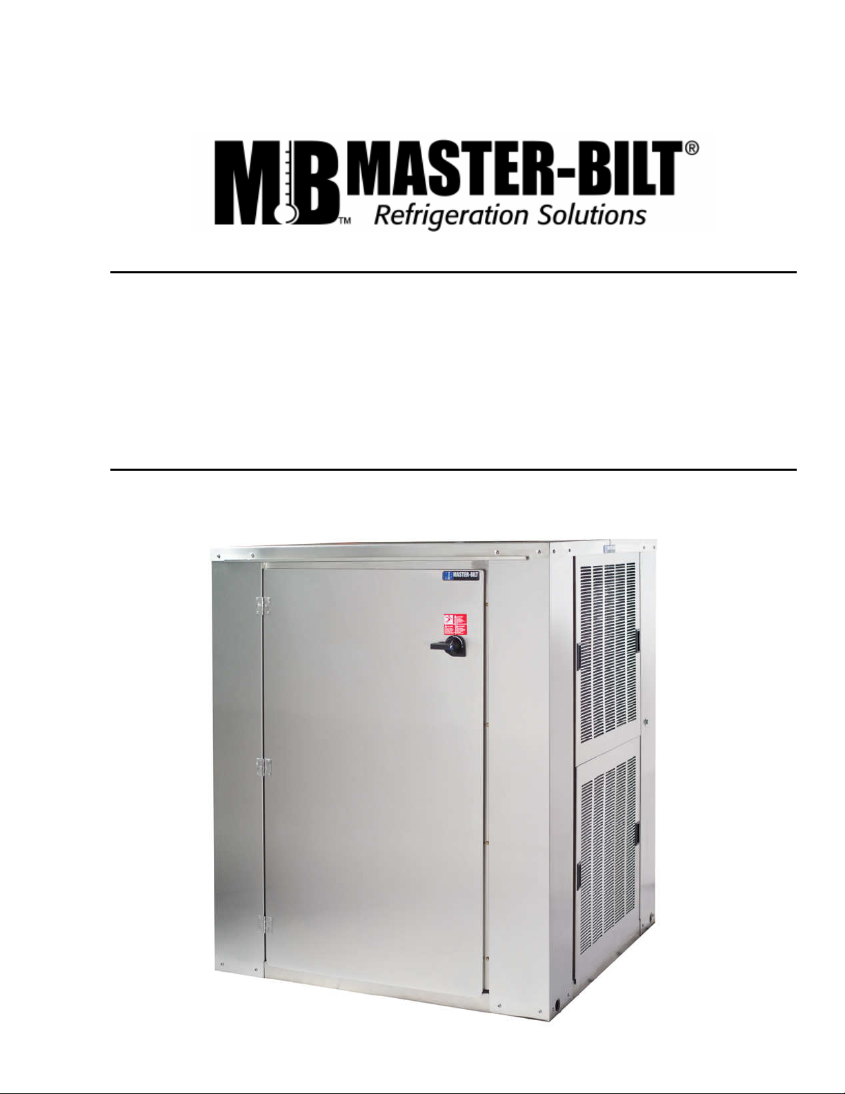
PS SERIES
PARALLEL RACK SYSTEM
INSTALLATION & OPERATIONS MANUAL
1st Revision (5-11-2010)
Page 2

TABLE OF CONTENTS
INTRODUCTION……………………………………………………………………………………………..3
WARNING LABES AND SAFETY INSTRUCTIONS…………………………………………………….4
PS SERIES FEATURES…………………………………………..………………………………………...5
PS SYSTEM NOMENCLATURE……………….…………………………………………………………..6
PRE-INSTALLATION INSTRUCTIONS…………………………………………………………….……..7
General Information…………………………………………………………………………………….…………7
Delivery Inspection………………………………………………………………………………………….….…7
INSTALLATION INSTRUCTIONS…………………………………………………………….………...…7
Handling and Placement of Walk-In Evap(s)………………………………………………………………...…7
Electrical Specifications………………………………………………………………………………………. …8
Refrigerant Piping……………………………………………………………………………………………..…..9
Suction and Liquid Line Sizes………………………………………………………………………..…………10
Leak Check…………………………………………………………………………………………………….….11
Evacuation, Dehydration, and Start-Up………………………………………………………………….....….11
Evacuation Procedure……………………………………………………………………………..……11
Finishing Charging Procedure…………………………………………………………………......….12
Low Ambient Charging (Example)……………………………………………………………...….....13
Handling and Placement of Multiple Rack System…………………………………………………………....7
STARTUP………………………………………………………..………………………………..….........15
SALE AND DISPOSAL……………………………………………………………………………..….…17
LABOR WARRANTY……………………………………………………………………………………..17
TYPICAL PIPING SCHEMATIC…………………………………………………………………...........18
PHYSICAL DIMENSIONS………………………..……………………………………………. .......19-22
OTHER SPECIFICATIONS & DIAGRAMS……..…………………….........................................23-27
2
Page 3
INTRODUCTION
Thank you for purchasing Master-Bilt refrigeration equipment. This manual contains important instructions for
installation, use and service. Read this entire manual carefully before installing or servicing your Master-Bilt equipment.
NOTICE
Installation and service of the refrigeration and electrical components must be performed by a refrigeration
mechanic or licensed electrician.
DANGER
Equipment MUST be properly grounded.
Improper or faulty hook-up of electrical components of the refrigeration units can result in severe injury or
death. All electrical wiring hook-ups must be done in accordance with all applicable local, regional or national
standards.
NOTICE
Read this manual before installing your refrigeration equipment. Keep the manual and refer to it before doing
any service. Failure to do so could result in personal injury or equipment damage.
The portions of this manual covering refrigeration and electrical components contain technical instructions intended only
for persons qualified to perform refrigeration and electrical work.
This manual cannot cover every installation, use, or service situation. If you need additional information, call or write us:
Parts and Technical Service Department
Master-Bilt Products
908 Highway 15 North
New Albany, MS 38652
Phone (800) 684-8988
Email: service@master-bilt.com
3
Page 4
WARNING LABELS AND SAFETY INSTRUCTIONS
damage to your equipment.
Be sure you understand all safety messages and always follow recommended precautions and safe operating practices.
You must make sure that everyone who installs, uses, or services your refrigeration equipment is thoroughly
familiar with all safety information and procedures.
Important safety information is presented in this section and throughout the manual. The following signal words are
used in the warnings and safety messages:
DANGER:
WARNING:
CAUTION:
NOTICE:
damage your refrigeration.
The warning and safety labels shown throughout this manual are placed on your Master-Bilt Products
refrigeration at the factory. Follow all warning label instructions. If any warning or safety labels become lost or
damaged, call your customer service department at (800) 684-8988 for replacements.
This is the safety-alert symbol. When you see this symbol, be alert to the potential for personal injury or
NOTICE TO EMPLOYERS
Severe injury or death WILL occur if you ignore the message.
Severe injury or death CAN occur if you ignore the message.
Minor injury or damage to your refrigeration can occur if you ignore the message.
This is important installation, operation or service information. If you ignore the message, you may
This Label is located on the condensing unit
4
Page 5

PS SERIES PARALLEL RACK FEATURES
• Generously sized condenser for high efficiency. Sized to operate efficiently in high ambient conditions.
• Hermetic, semi-hermetic, and Scroll compressors in any combination the customer chooses
• Generously sized receivers with isolation valves and liquid level indicator
• Compressor Suction Service Valves with Access Ports, and Discharge Line Service Valves with Access Ports
• Pre-wired and mounted high and low pressure controls with each compressor
• Units leak tested
• U.L. listed
• Easy accessibility for service
• Pre-wired for easy installation with Single Point Electrical Connection with individual Circuit Breakers for each
Compressor and Through Door Main Disconnect Switch and Circuit Breaker Installed
• Crankcase Heater Installed for each Compressor
• Refrigeration lines pre-piped to edge of unit
• Pre-piped and mounted refrigerant sight glass
• Flooded Head Pressure Controls standard on each system. Other options available
• Galvanized steel housing is standard, Stainless Steel Housing optional
• Engineered Refrigeration Drawing Available for Specified Projects, or with Purchase Order (Contact Factory for
Additional Details)
• Master-Controller Electronic Refrigeration Controls for Maximum Energy Efficiency are available for use with
parallel racks.
• Replaceable core suction and liquid filter driers.
• Oil return system complete with oil separator, oil level controls and oil filter are standard.
• Two tiered frame/cabinet typically contains up to 12 compressors. Compressors are numbered starting from
the upper left. If a split suction system is used, low temperature compressors are typically on the top tier.
• Up to 3 suction groups can be controlled within a single frame/cabinet.
• Hot gas defrost, electric defrost, off cycle defrost
• Heat reclaim available
• Split condenser available
• Floating head pressure control available
• EVI compressors with sub cooled liquid available
• Various alarms available including compressor failure, liquid level, etc are available. Standard alarms include
phase loss and oil failure.
5
Page 6
-
C = 208-230/3/60
E = 460/3/60
Z = R404A
1 to 3
2 to 8
R = Remote
C = Mounted on Common Frame
A = Air Cooled
W = Water Cooled
Parallel Rack Nomenclature
PS E C 5 2 Z CA
XXXXX
Quote Number
Voltage
Refrigerant
Number of Suction Groups
Number of Compressors
Condenser Location
Condensing Method
Frame
I = Interior
E = Exterior
Parallel Rack
6
Page 7

PRE-INSTALLATION INSTRUCTIONS
I. GENERAL INFORMATION
Please read this manual prior to installing your Master-Bilt equipment. This information is based on good refrigeration
practice and should be used as a guide for installation and operation.
II.
DELIVERY INSPECTION
You are responsible for filling all freight claims with the delivering truck line. Inspect all cartons and crates for damage
as soon as they arrive. If damage is noted to shipping crates or cartons or a shortage is found, note this on the bill of
lading (all copies) prior to signing.
If damage is discovered when the cabinet arrives, immediately call the delivering truck line and follow up the call with a
written report indicating concealed damaged to your shipment. Ask for an immediate inspection of your concealed item.
Crating material MUST be retained (if applicable) to show the inspector representing the truck line.
INSTALLATION INSTRUCTIONS
I.
HANDLING AND PLACEMENT OF PARALLEL RACK SYSTEM
There should be a minimum of 3 feet around the perimeter of the Rack System that should be unobstructed.
This allows for proper servicing of the equipment. Please refer to local and state codes as well at the NEC for
additional clearance requirements.
Holes are provided in the base supports for mounting bolts and for bridle lift rods.
For indoor mounting, motor rooms should be provided with fans designed to move 100 CFM of air per one ton of
refrigeration capacity.
7
Page 8
II. ELECTRICALSPECIFICATIONS
Electrical power supply must match the rack power
requirements indicated on the unit data plate. A WIRING
DIAGRAM IS LOCATED ON THE INSIDE ON THE
ELECTRICAL BOX COVER. For best results, it is
suggested that power supply for PS Rack systems be
applied as illustrated below in Figure 1. All field wiring
should be done in a professional manner, in accordance
with all governing codes. All wiring (including factory
terminals) should be double checked before start-up
Wiring diagrams specific to each installation will be provided
by Master-Bilt.
Figure 1: Suggested Field Wiring Location for PS Units.
NOTICE!
Systems with scroll compressors must be checked for proper power phasing. Improper power phasing will result in
improper compressor rotation causing compressor to pump incorrectly. A phase monitor is standard on PS systems for
this purpose.
Three phase scroll compressors are directional dependent, i.e., they will only compress in one rotational direction and
will rotate in either direction depending on power phasing. Verification of proper rotational direction is made by
observing that suction pressure drops and discharge pressure rises when the compressor is energized. Reverse
rotation also results in an elevated sound level over correct rotation, as well as substantially reduced current draw
compared to data tag values.
NOTICE!
Check phase alignment on all incoming power.
8
Page 9
III.
Fitting
Tee
Tee
Size
90º Ell
45º Ell
(Line)
(Branch)
REFRIGERANT PIPING
Use only refrigeration grade copper tubing, (ACR), type “L”, bright annealed, dehydrated, and properly sealed against
contamination. Soft temper tubing may not be used for field interconnection of refrigeration components. Take extreme
care to keep refrigeration tubing clean and dry prior to installation. Use an appropriate size tube cutter. Remove any
burring that may occur when cutting the tubing. Use dry nitrogen to purge the system of any foreign objects that may
have come about during any pipe cutting.
All suction lines will be insulated with not less than ¾” Armaflex or acceptable substitute as determined by Master-Bilt
personnel. Armaflex insulation must be properly glued or taped as approved by insulation manufacturer to prevent
refrigeration lines from “sweating”.
Appropriate oil must be added to systems per Compressor manufacturer specifications.
Suction lines should be sloped down ½” for each 10 feet of horizontal run towards the compressor. This will facilitate
good oil return to the compressor.
Refrigeration lines will be sized appropriately to facilitate
proper oil return to the compressor and reduce refrigerant
line pressure drop. Table 1 depicts proper line sizing
options. Use this as a guideline for your selection.
Any fittings used may be accounted for in the Table to the
right.
1/2" 0.9 0.4 0.8 2
5/8" 1 0.5 1 2.5
7/8" 1.5 0.7 1.5 3.5
1-1/8" 1.8 0.9 1.5 4.5
1-3/8" 2.4 1.2 1.8 6
1-5/8" 2.8 1.4 2 7
2-1/8" 3.9 1.8 3.8 10
Equivalent Length Allowances for Pipe Fittings
(length in feet)
9
Page 10

160000
R-404a Suction and Liquid line sizes
20F suction temperature 10F suction temperature -15F suction temperature -25F suction temperature -35F suction temperature All
System
Capacity suction line suction line suction line suction line suction line suction line suction line suction line suction line suction line suction line suction line suction line suction line suction line liquid
BTU/Hr. horiz. vert. horiz. vert. horiz. vert. horiz. vert. horiz. vert. horiz. vert. horiz. vert. horiz. vert. horiz. vert. horiz. vert. horiz. vert. horiz. vert. horiz. vert. horiz. vert. horiz. vert. line
1500
2000
3000
4000
5000
6000
7000
8000
9000
10000
12000
14000
16000
18000
20000
25000
30000
35000
40000
45000
50000
60000
70000
80000
90000
100000
110000
120000
130000
140000
150000
50' 100' 200' 50' 100' 200' 50' 100' 200' 50' 100' 200' 50' 100' 200'
3/8 5/16 3/8 5/16 1/2 5/16 3/8 5/16 1/2 5/16 1/2 5/16 1/2 3/8 1/2 3/8 5/8 3/8 1/2 3/8 5/8 3/8 5/8 3/8 1/2 1/2 5/8 1/2 3/4 1/2 1/4
3/8 5/16 1/2 5/16 1/2 5/16 3/8 3/8 1/2 3/8 1/2 3/8 1/2 3/8 5/8 3/8 5/8 3/8 1/2 1/2 5/8 1/2 3/4 1/2 5/8 1/2 5/8 1/2 3/4 1/2 1/4
1/2 3/8 1/2 3/8 5/8 3/8 1/2 3/8 1/2 3/8 5/8 3/8 5/8 1/2 5/8 1/2 3/4 1/2 5/8 1/2 3/4 1/2 3/4 1/2 5/8 5/8 3/4 5/8 7/8 5/8 5/16
1/2 3/8 1/2 3/8 5/8 3/8 1/2 3/8 5/8 3/8 5/8 3/8 5/8 1/2 3/4 1/2 3/4 1/2 5/8 5/8 3/4 5/8 7/8 5/8 3/4 3/4 7/8 3/4 7/8 3/4 5/16
1/2 3/8 5/8 3/8 5/8 3/8 5/8 1/2 5/8 1/2 3/4 1/2 5/8 5/8 3/4 5/8 7/8 5/8 3/4 3/4 7/8 3/4 7/8 3/4 3/4 7/8 7/8 7/8 1 1/8 7/8 3/8
5/8 1/2 5/8 1/2 5/8 1/2 5/8 1/2 5/8 1/2 3/4 1/2 3/4 5/8 3/4 5/8 7/8 5/8 3/4 3/4 7/8 3/4 1 1/8 3/4 7/8 7/8 1 1/8 7/8 1 1/8 7/8 3/8
5/8 1/2 5/8 1/2 3/4 1/2 5/8 1/2 3/4 1/2 3/4 1/2 3/4 3/4 7/8 3/4 1 1/8 3/4 7/8 7/8 7/8 7/8 1 1/8 7/8 7/8 7/8 1 1/8 7/8 1 1/8 7/8 3/8
5/8 1/2 3/4 1/2 3/4 1/2 5/8 5/8 3/4 5/8 7/8 5/8 3/4 3/4 7/8 3/4 1 1/8 3/4 7/8 7/8 1 1/8 7/8 1 1/8 7/8 7/8 7/8 1 1/8 7/8 1 1/8 7/8 3/8
5/8 1/2 3/4 1/2 3/4 1/2 5/8 5/8 3/4 5/8 7/8 5/8 7/8 7/8 7/8 7/8 1 1/8 7/8 7/8 7/8 1 1/8 7/8 1 1/8 7/8 1 1/8 1 1/8 1 1/8 1 1/8 1 3/8 1 1/8 3/8
5/8 5/8 3/4 5/8 7/8 5/8 3/4 5/8 3/4 5/8 7/8 5/8 7/8 7/8 1 1/8 7/8 1 1/8 7/8 7/8 7/8 1 1/8 7/8 1 1/8 7/8 1 1/8 1 1/8 1 1/8 1 1/8 1 3/8 1 1/8 3/8
3/4 5/8 3/4 5/8 7/8 5/8 3/4 3/4 7/8 3/4 1 1/8 3/4 7/8 7/8 1 1/8 7/8 1 1/8 7/8 1 1/8 1 1/8 1 1/8 1 1/8 1 3/8 1 1/8 1 1/8 1 1/8 1 3/8 1 1/8 1 3/8 1 1/8 1/2
3/4 3/4 7/8 3/4 7/8 3/4 3/4 3/4 7/8 3/4 1 1/8 3/4 1 1/8 7/8 1 1/8 7/8 1 3/8 7/8 1 1/8 1 1/8 1 1/8 1 1/8 1 3/8 1 1/8 1 1/8 1 1/8 1 3/8 1 3/8 1 3/8 1 3/8 1/2
3/4 3/4 7/8 3/4 1 1/8 3/4 7/8 7/8 7/8 7/8 1 1/8 7/8 1 1/8 1 1/8 1 1/8 1 1/8 1 3/8 1 1/8 1 1/8 1 1/8 1 3/8 1 1/8 1 3/8 1 1/8 1 1/8 1 1/8 1 3/8 1 3/8 1 5/8 1 3/8 1/2
3/4 3/4 7/8 3/4 1 1/8 3/4 7/8 7/8 1 1/8 7/8 1 1/8 7/8 1 1/8 1 1/8 1 1/8 1 1/8 1 3/8 1 1/8 1 1/8 1 1/8 1 3/8 1 3/8 1 5/8 1 3/8 1 3/8 1 3/8 1 3/8 1 3/8 1 5/8 1 3/8 1/2
7/8 7/8 7/8 7/8 1 1/8 7/8 7/8 7/8 1 1/8 7/8 1 1/8 7/8 1 1/8 1 1/8 1 3/8 1 1/8 1 3/8 1 1/8 1 1/8 1 1/8 1 3/8 1 3/8 1 5/8 1 3/8 1 3/8 1 3/8 1 3/8 1 3/8 1 5/8 1 5/8 1/2
7/8 7/8 1 1/8 7/8 1 1/8 7/8 1 1/8 7/8 1 1/8 7/8 1 3/8 7/8 1 1/8 1 1/8 1 3/8 1 3/8 1 5/8 1 3/8 1 1/8 1 1/8 1 3/8 1 5/8 1 5/8 1 5/8 1 3/8 1 3/8 1 5/8 1 5/8 2 1/8 1 5/8 5/8
7/8 7/8 1 1/8 7/8 1 3/8 7/8 1 1/8 1 1/8 1 1/8 1 1/8 1 3/8 1 1/8 1 3/8 1 3/8 1 3/8 1 3/8 1 5/8 1 3/8 1 3/8 1 3/8 1 5/8 1 5/8 2 1/8 1 5/8 1 3/8 1 3/8 1 5/8 1 5/8 2 1/8 1 5/8 5/8
1 1/8 1 1/8 1 1/8 1 1/8 1 3/8 1 1/8 1 1/8 1 1/8 1 3/8 1 1/8 1 3/8 1 1/8 1 3/8 1 3/8 1 5/8 1 5/8 1 5/8 1 5/8 1 3/8 1 3/8 1 5/8 1 5/8 2 1/8 1 5/8 1 5/8 1 5/8 2 1/8 2 1/8 2 1/8 2 1/8 5/8
1 1/8 1 1/8 1 1/8 1 1/8 1 3/8 1 1/8 1 1/8 1 1/8 1 3/8 1 3/8 1 3/8 1 3/8 1 3/8 1 3/8 1 5/8 1 5/8 2 1/8 1 5/8 1 5/8 1 5/8 1 5/8 1 5/8 2 1/8 1 5/8 1 5/8 1 5/8 2 1/8 2 1/8 2 1/8 2 1/8 3/4
1 1/8 1 1/8 1 3/8 1 1/8 1 3/8 1 1/8 1 3/8 1 3/8 1 3/8 1 3/8 1 5/8 1 3/8 1 3/8 1 3/8 1 5/8 1 5/8 2 1/8 1 5/8 1 5/8 1 5/8 2 1/8 2 1/8 2 1/8 2 1/8 1 5/8 1 5/8 2 1/8 2 1/8 2 1/8 2 1/8 3/4
1 1/8 1 1/8 1 3/8 1 3/8 1 3/8 1 3/8 1 3/8 1 3/8 1 3/8 1 3/8 1 5/8 1 3/8 1 5/8 1 5/8 1 5/8 1 5/8 2 1/8 1 5/8 1 5/8 1 5/8 2 1/8 2 1/8 2 1/8 2 1/8 2 1/8 2 1/8 2 1/8 2 1/8 2 5/8 2 5/8 3/4
1 1/8 1 1/8 1 3/8 1 3/8 1 5/8 1 3/8 1 3/8 1 3/8 1 5/8 1 5/8 1 5/8 1 5/8 1 5/8 1 5/8 2 1/8 2 1/8 2 1/8 2 1/8 2 1/8 2 1/8 2 1/8 2 1/8 2 5/8 2 1/8 2 1/8 2 1/8 2 1/8 2 1/8 2 5/8 2 5/8 7/8
1 3/8 1 3/8 1 3/8 1 5/8 1 5/8 1 5/8 1 3/8 1 3/8 1 5/8 1 5/8 2 1/8 1 5/8 1 5/8 1 5/8 2 1/8 2 1/8 2 1/8 2 1/8 2 1/8 2 1/8 2 1/8 2 1/8 2 5/8 2 5/8 2 1/8 2 1/8 2 5/8 2 5/8 2 5/8 2 5/8 7/8
1 3/8 1 3/8 1 5/8 1 5/8 1 5/8 1 5/8 1 3/8 1 3/8 1 5/8 1 5/8 2 1/8 1 5/8 2 1/8 2 1/8 2 1/8 2 1/8 2 5/8 2 1/8 2 1/8 2 1/8 2 1/8 2 1/8 2 5/8 2 5/8 2 1/8 2 1/8 2 5/8 2 5/8 2 5/8 2 5/8 7/8
1 3/8 1 3/8 1 5/8 1 5/8 2 1/8 1 5/8 1 5/8 1 5/8 1 5/8 1 5/8 2 1/8 1 5/8 2 1/8 2 1/8 2 1/8 2 1/8 2 5/8 2 5/8 2 1/8 2 1/8 2 5/8 2 5/8 2 5/8 2 5/8 2 1/8 2 1/8 2 5/8 2 5/8 3 1/8 3 1/8 7/8
1 3/8 1 3/8 1 5/8 1 5/8 2 1/8 1 5/8 1 5/8 1 5/8 2 1/8 2 1/8 2 1/8 2 1/8 2 1/8 2 1/8 2 1/8 2 1/8 2 5/8 2 5/8 2 1/8 2 1/8 2 5/8 2 5/8 2 5/8 2 5/8 2 5/8 2 5/8 2 5/8 2 5/8 3 1/8 3 1/8 7/8
1 5/8 1 5/8 1 5/8 1 5/8 2 1/8 1 5/8 1 5/8 1 5/8 2 1/8 2 1/8 2 1/8 2 1/8 2 1/8 2 1/8 2 1/8 2 1/8 2 5/8 2 5/8 2 1/8 2 1/8 2 5/8 2 5/8 3 1/8 3 1/8 2 5/8 2 5/8 2 5/8 2 5/8 3 1/8 3 1/8 7/8
1 5/8 1 5/8 2 1/8 1 5/8 2 1/8 1 5/8 1 5/8 1 5/8 2 1/8 2 1/8 2 1/8 2 1/8 2 1/8 2 1/8 2 5/8 2 5/8 2 5/8 2 5/8 2 5/8 2 5/8 2 5/8 2 5/8 3 1/8 3 1/8 2 5/8 2 5/8 2 5/8 2 5/8 3 1/8 3 1/8 1 1/8
1 5/8 1 5/8 2 1/8 2 1/8 2 1/8 2 1/8 1 5/8 1 5/8 2 1/8 2 1/8 2 1/8 2 1/8 2 1/8 2 1/8 2 5/8 2 5/8 2 5/8 2 5/8 2 5/8 2 5/8 2 5/8 2 5/8 3 1/8 3 1/8 2 5/8 2 5/8 3 1/8 3 1/8 3 5/8 3 5/8 1 1/8
1 5/8 1 5/8 2 1/8 2 1/8 2 1/8 2 1/8 2 1/8 2 1/8 2 1/8 2 1/8 2 5/8 2 1/8 2 1/8 2 1/8 2 5/8 2 5/8 3 1/8 3 1/8 2 5/8 2 5/8 2 5/8 2 5/8 3 1/8 3 1/8 2 5/8 2 5/8 3 1/8 3 1/8 3 5/8 3 5/8 1 1/8
1 5/8 1 5/8 2 1/8 2 1/8 2 1/8 2 1/8 2 1/8 2 1/8 2 1/8 2 1/8 2 5/8 2 5/8 2 1/8 2 1/8 2 5/8 2 5/8 3 1/8 3 1/8 2 5/8 2 5/8 3 1/8 3 1/8 3 1/8 3 1/8 2 5/8 2 5/8 3 1/8 3 1/8 3 5/8 3 5/8 1 1/8
1 5/8 1 5/8 2 1/8 2 1/8 2 1/8 2 1/8 2 1/8 2 1/8 2 1/8 2 1/8 2 5/8 2 5/8 2 5/8 2 5/8 2 5/8 2 5/8 3 1/8 3 1/8 2 5/8 2 5/8 3 1/8 3 1/8 3 1/8 3 1/8 2 5/8 2 5/8 3 1/8 3 1/8 3 5/8 3 5/8 1 1/8
Table 1
10
Page 11

All vertical risers will have an appropriate “P” trap at the beginning of the riser and every 20 ft above this point. If the
total rise is less distance than can be evenly divided by 20, the P-traps will be located at the beginning and in the center
of the distance so that the total distance between any two traps does not exceed 20 ft.
Keep the refrigeration lines as short as possible and use as few fittings as practicable, being especially careful not to
“kink” the lines. Keep the layout as simple as possible and properly support the piping to absorb vibration and the
normal expansion and contraction caused by temperature changes.
Add appropriate amount of oil per compressor manufacturer recommendations to compensate for oil return system
volume.
When brazing, dry nitrogen MUST be passed through the lines at low pressure to prevent scaling and oxidation inside
the tubing and fittings. All flux will be removed from the joints when brazing is complete.
MINIMIZE the amount of flux used to prevent internal contamination of the refrigeration system.
Silver brazing wire is to be utilized (high temperature alloy of minimum of 5% silver content on all copper connections,
and high temperature alloy of 45% silver content on all dissimilar metal connections.
The refrigeration contractor will be responsible for providing and installing the liquid line solenoid valve and coil and
evaporator pressure regulator for all loop piping systems unless otherwise requested by the customer. Consult the
refrigeration schedule for details.
V.
LEAK CHECK
When all refrigeration line connections have been made, the complete system, including factory connections, should be
checked.
Add the proper refrigerant to 60 psig, and then boost the 150 psig with dry nitrogen. Leak checks should be done on all
joints with an electronic leak detector or halide torch. If leaks are found, relieve the pressure and make repairs as
necessary and recheck. Verify that all valves have been re-opened and re-pressurize the system to 150 psig as before
for at least 12 hours. System pressure should not change during this time. Pressurizing the system above 150 psig
may damage the suction pressure transducers. Do not apply pressure above 150 psig to these transducers.
VI. EVACUATION, DEHYDRATION, AND START-UP
A vacuum of 500 microns or less must be pulled to properly dehydrate the refrigeration system.
Do not use the system compressor as a vacuum pump.
Do not operate compressor while system is in a vacuum.
11
Page 12

Triple Evacuation Procedure
Additional lb of Refrigerant for Length of Ref. Line
25 Ft
50 Ft.
100 Ft.
Line (OD)
3/8
1/2
5/8
7/8
1 1/8
1 3/8
3/8
1/2
5/8
7/8
1 1/8
1 3/8
3/8
1/2
5/8
7/8
1 1/8
1 3/8
R-22
R-404A
A. Open all service valves and relieve system pressure. Also, open any line valves installed in the system and energize all
solenoid valves and EPR’s to facilitate evacuation.
B. Connect the vacuum pump to the high and low sides of the system. Connect a micron vacuum gauge to the system at
the point furthest away from the rack and another at the rack.
C. Leaks or moisture will be indicated if the system pressure rises when the vacuum line is closed off.
Pull a vacuum of 1500 microns, close vacuum line and “break” vacuum to 5 psig, maximum, with refrigerant to be used
in the system.
D. Install filter/drier cores and repeat step C.
E. A final vacuum of 500 microns should be pulled before charging. When 500 microns is reached, close vacuum line and
charge system with the proper refrigerant through a high side service valve.
Finishing Charging Procedures
A. Preliminary
With the system in a vacuum, liquid charge the system by adding refrigerant into the liquid side of the
system at a service valve provided. Add as much refrigerant as the system will take up to the holding
capacity of the receiver.
TABLE 5:
1.0 1.9 3.0 6.1 10.4 15.9 2.0 3.8 6.0 12.2 20.8 31.8 4.0 7.6 12.0 24.4 41.6 63.6
0.9 1.6 2.6 5.3 9.0 13.8 1.8 3.2 5.2 10.6 18.0 27.6 3.6 6.4 10.4 21.2 36.0 55.2
12
Page 13

B. Low Ambient Charging Procedure
All standard air cooled condensers on the PS Rack System are
equipped with a head pressure control valve to maintain proper head
pressure during winter conditions. These valves function by reducing
the effective condenser area by flooding or “backing up” refrigerant in
the condenser to reduce the amount of surface available for
condensing. To operate properly, more charge is required during this
flooding condition.
To use the chart, multiply the pounds of recommended pre-charge
obtained by adding the recommended pre-charge (Table 4) with the
additional refrigerant required for line set length (Table 5) by the
percent flooding required in Chart A to arrive at the additional charge
required.
Typical Head Pressure Control Valve
13
Page 14

Chart A:
14
Page 15

Example of Low Ambient Charging
Determine the additional charge to operate a CHHX035C at suction temp +20ºF and the unit
is charged at +50ºF. Assume a 100 ft. line set (horizontal).
1. Capacity for CHHX035C @ +20ºF = 24,800 BTUH
2. Choose the proper refrigeration lines base on capacity from Table 1, suction line = 1 1/8”, liquid line = ½”.
3. Look up the recommended pre-charge from Table 4 for CHHX035C (8.5 lbs of R-22).
4. From Table 5, find the additional refrigerant (R-22 in this case) required for a ½” liquid line of length 100 ft.
(7.6 lb of R-22)
5. Add these two values to get 16.1 lbs of R-22.
6. Look at Chart A to obtain multiplier. The horizontal axis of Chart A yields the ambient charging temperature
(50º). The vertical axis of Chart A yields the multiplier. Notice there are several graphs in this chart. Select
the graph corresponding to your desired suction temperature. In this case, 20ºF. One can now see that the
condenser should be flooded at 32% to operate correctly.
7. Multiply 16.1 lbs of R-22 by 32% to get 5.15 lbs of additional charge.
8. Again, finish charging until desire superheat settings are obtained.
START UP
1) Set all low-pressure controls.
2) Add refrigerant oil to the oil reservoir until oil is shown in upper glass.
3) Verify all loads are in refrigeration mode
4) Verify the condenser is turned on
5) Verify that all compressor and control breakers and toggle switches are in the off position and apply power
to the unit. Check the phase monitor to verify that the green light is illuminated. Verify that the correct
voltage is connected to unit.
6) Turn on the control circuit breaker. This will activate the electronic controls. Review the main rack controller
setpoints.
7) Verify the actual suction header pressure with an accurate refrigeration gauge. Calibrate as necessary.
8) With the compressor control circuit switches remaining in the off position, turn on the compressor circuit
breakers.
15
Page 16

9) Making sure refrigeration gauges are connected to the low and high sides of the system, turn on the switch
to the lead compressor in the highest suction pressure group. Allow the compressor to pull the suction
down to the operating pressure of the system then continue turning on compressors until all are activated.
Repeat for the next lower suction pressure group.
10) Set the pressure regulating valves
11) Set and check expansion valve superheat on each case and cooler while the EPR valve is in the position.
12) Set each EPR valve for all loads/lineups. Suction header pressure must be lower than the EPR setting
before performing this step.
13) Adjust all EPR valves as necessary to maintain proper fixture temperature. Also check expansion valve
superheat.
14) Verify that the condenser is maintaining the head pressure set point and liquid level in receiver.
15) Check refrigerant level in receiver and add as necessary. Minimum level is 20% in the coldest weather for
area.
16) Verify defrost settings including defrost times and termination temperatures. No more than 25% of the total
load should be in defrost at one time.
17) Check oil reservoir after two (2) days of operation and add oil as necessary.
18) After all adjustments have been made, check all valves for proper stem position and replace valve caps.
19) Recheck all capillary tubes on all pressure controls to be sure that they are properly secured and free of
vibration.
16
Page 17

SALE AND DISPOSAL
If you sell or give away your refrigeration equipment system or components you must make sure that all safety labels
and I&O Manuals are included. If you need replacement labels or manuals, contact the parts and technical service
department at Master-Bilt at (800) 684-8988
The customer service department at Master-Bilt should be contacted at the time of sale or disposal of your equipment
so records may be kept of its new location.
If you sell or give away your Master-Bilt cabinet and you evacuate the refrigerant charge before shipping, you must
evacuate the refrigerant into an approved recovery and reclaim system in order to satisfy all applicable federal and state
regulations regarding release of refrigerant compounds into the atmosphere.
The release of refrigerant compounds into the atmosphere is a source of ozone depletion and regulated by
state and federal laws.
LABOR WARRANTY
A. A 90 day labor warranty will be provided on all installer provided labor and installation.
B. A 1 year optional Labor warranty will be quoted separate from the installation.
C. Master-Bilt will provide a one year parts warranty on all parts that fail under normal operation conditions.
17
Page 18

TYPICAL PS SERIES PIPING SCHEMATIC
18
Page 19

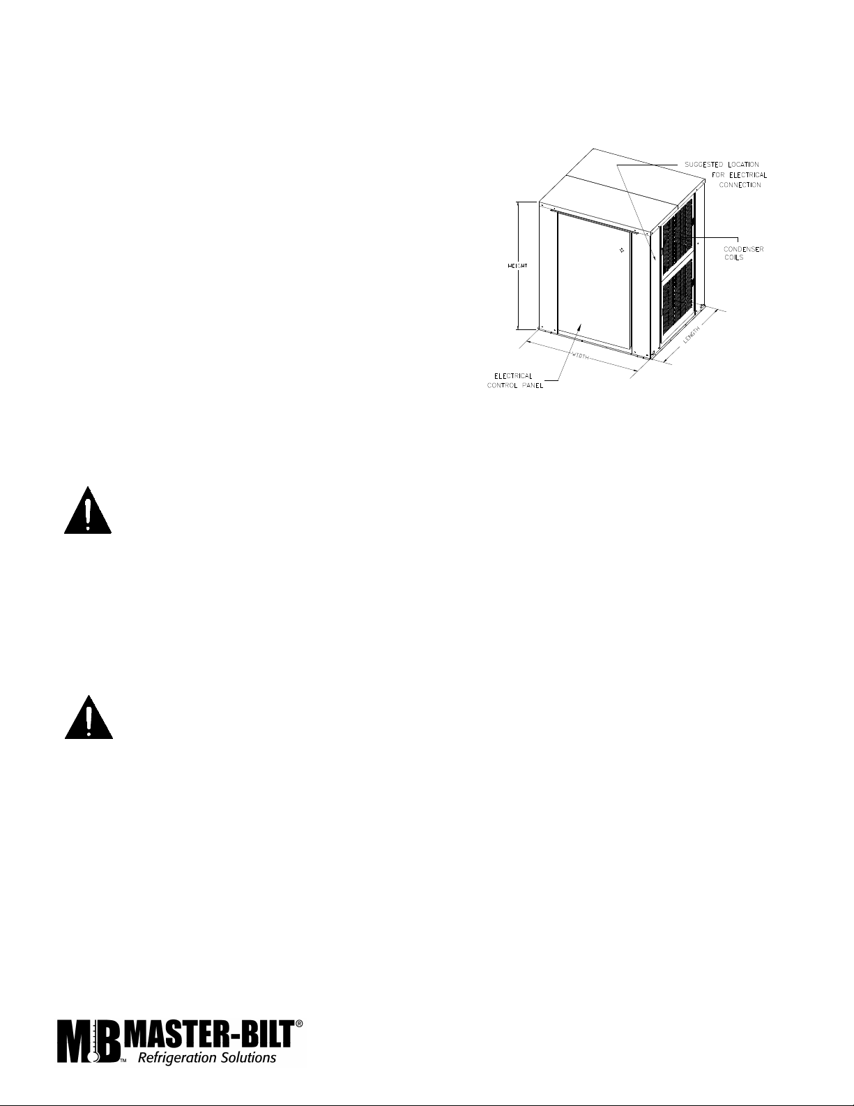
PS-1B PHYSICAL DIMENSIONS
19
Page 20

PS-2B PHYSICAL DIMENSIONS
20
Page 21

PS-3B PHYSICAL DIMENSIONS
21
Page 22

PS-4B PHYSICAL DIMENSIONS
22
Page 23

23
Page 24

24
Page 25

.
25
Page 26

26
Page 27

DI1
27
 Loading...