

Page 1
1
Deluxe Ice Cream Dipping/Display Merchandisers
Installation & Operations Manual
ControlTec TLY25
Master-Bilt Products
908 Highway 15 North
New Albany, MS 38652
Phone: (800) 684-8988
Rev 6-10-11
Page 2

2
Page 3

3
TABLE OF CONTENTS
INTRODUCTION………………………………….…………………………………………………………………... 4
STORE CONDITIONS…………………………….……………….…..…………………………………………….. 4
WARNING LABELS AND SAFETY INSTRUCTIONS………..…..……………………………………………… 5
PRE-INSTALLATION INSTRUCTIONS………………………..…..……………………………… ….…………… 5
Inspection for Shipping Damage…………………………………………………………….…………….. 5
INSTALLATION INSTRUCTIONS………………………………………………………………………………….. 6
General Instructions…………………………………………………………………………………………. 6
Electrical…..………………………………………………………………………………………………….. 6
Mechanical…………………………………………………………………………………………………… 7
Startup………………………………………………………………………………………………………. 7
ControlTec Electronic CONTROL.…………………………………………………………………………… …8-9
CLEANING INSTRUCTIONS……………………………………………………………………………………..…10
Can Holder Cleaning………………………………………………………………………………………...10
Frost Shield Cleaning……………………………….……………………………………………………….10
OPERATION CONDITIONS AND PRESSURES …………………………………………………………………11
SERVICE INSTRUCTIONS (Trouble Shooting )………………………………………………………………….11
MASTER-BILT PART NUMBERS………………………………………………………………………………….. 12
ACCESSORIES………………………………………………………………………………………………………...13
SALE AND DISPOSAL……………………………………………………………………………… ………………. 13
WIRING DIAGRAMS.……………………………………………………………………………………………...14-15
Page 4
4
INTRODUCTION
Thank you for purchasing a Master-Bilt cabinet. This manual contains important instructions for installing, using and
servicing a Master-Bilt DD_LCG case. A parts list is included in with this manual. Read all these documents carefully
before installing or servicing your equipment.
STORE CONDITIONS
The Master-Bilt DD_LCG cases are designed to operate in the controlled environment of an air-conditioned store. The
store temperature should be at or below 75°F and a relative humidity of 55% or less. At higher temperature or humidity
conditions, the performance of these cases may be affected and the capacity diminished. It is not uncommon in a newly
constructed store for the temperature and humidity to be above design conditions. These excessive conditions may
produce sweating in the case until the store is operational and the ambient environment is more desirable.
The Master-Bilt DD_LCG should not be positioned where it is directly exposed to rays of sun or near a direct source of
radiant heat or airflow. This will adversely affect the case and will result in poor performance.
NOTICE
Read this manual before installing your cabinet. Keep the manual and refer to it before doing any service on
the equipment. Failure to do so could result in personal in jury or damage to the cabinet.
DANGER
Improper or faulty hook-up of electrical components of the refrigeration units can result in severe injury or
death.
All electrical wiring hook-ups must be done in accordance with all applicable local, regional or national
standards.
NOTICE
Installation and service of the refrigeration and electrical components of the cabinet must be performed by a
refrigeration mechanic and/or a licensed electrician
The portions of this manual covering refrigeration and electrical components contain technical instructions intended only
for persons qualified to perform refrigeration and electrical work.
This manual cannot cover every installation, use or service situation. If you need additional information have the serial
number at hand and call or write us:
Customer Service Department
Master-Bilt Products
Highway 15 North
New Albany, MS 38652
Phone (800) 684-8988
Fax (800) 684-8988
Page 5
5
CAUTION!
GROUND REQUIRED
FOR SAFE OPERATION
WARNING LABELS AND SAFETY INSTRUCTIONS
This symbol is the safety-alert symbol. When you see this symbol on your cabinet or in this
manual, be alert to the potential for personal injury or damage to your equipment.
Be sure you understand all safety messages and always follow recommended precautions and safe operating practices.
NOTICE TO EMPLOYERS
You must make sure that everyone who installs, uses or services your cabinet is thoroughly familiar with all
safety information and procedures.
Important safety information is presented in this section and throughout this section and throughout the manual. The
following signal words are used in the warnings and safety messages:
DANGER: Severe injury or death will occur if you ignore the message.
WARNING: Severe injury or death can occur if you ignore the message.
CAUTION: Minor injury or damage to your cabinet can occur if you ignore the message.
NOTICE: This is important installation, operation or service information. If you ignore the
message, you may damage your cabinet.
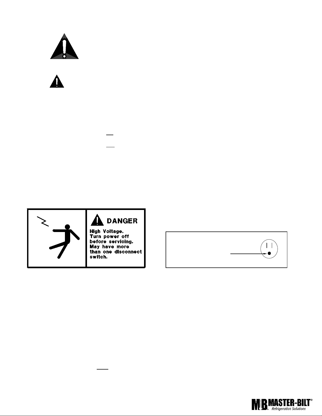
The warning and safety labels shown throughout this manual are placed on your Master-Bilt Products cabinet
at the factory. Follow all warning label instructions. If any warning or safety labels become lost or damaged,
call your customer service department at (800) 684-8988 for replacements.
This label is located on top of the electrical control This label is attached to the cabinet power cord
label and on the wiring channel. on models with a power cord.
PRE-INSTALLATION INSTRUCTIONS
INSPECTION FOR SHIPPING DAMAGE
You are responsible for filing all freight claims with the delivering truck line. Inspect all cartons and crates for damage as
soon as they arrive. If damage is noted to shipping crates or cartons or if a shortage is found, note this on the b ill of
lading (all copies) prior to signing.
If damage is discovered when the cabinet is uncrated, immediately call the delivering truck line and follow up the call with
a written report indicating concealed damage to your shipment. Ask for an immediate inspection of your concealed
damage item. Crating material must be retained to show the inspector from the truck line.
Page 6

6
INSTALLATION INSTRUCTIONS
GENERAL INSTRUCTIONS
1. Be sure the equipment is properly installed by competent service people.
2. Keep the equipment clean and sanitary so it will meet your local sanitation codes.
3. Rotate your stock so that older stock does not accumulate. This is especially important for ice
cream. A "First-In, First-Out" rotation practice will keep the products in good salable condition.
4. Do not place product in the case when it is soft or partially thawed. Also, product should not be put in the case for at
least 6 hours after it is started.
5. Stock cases as quickly as possible, exposing only small quantities to store temperatures for short periods of time.
6. When replacing burned out fluorescent tubes, be sure that the electrical power to the lighting circuit is turned off.
NOTICE TO STORE OWNERS / MANAGERS
Moisture or liquid around or under the cabinet is a potential slip/fall hazard for persons walking by or working
in the general area of the cabinet. Any cabinet malfunction or housekeeping problem that creates a slip/fall
hazard around or under the cabinet should be corrected immediately.
If moisture or liquid is observed around or under a Master-Bilt cabinet, an immediate investigation should be made by
qualified personnel to determine the source of the moisture or liquid. The investigation should determine if the cabinet is
malfunctioning or if there is a drainpipe leaking.
ELECTRICAL
WARNING
Before servicing electrical components in the case, make sure all power to case is off. Always use a qualified
technician.
Page 7

7
MECHANICAL
Remove grille and check refrigeration lines to see that they are free (not touching each other or compressor).
Spin condenser fan blade to see that it is free.
Check that all service valves are open.The picture below is Master-Bilt’s standard DD-Unit. The compressor is hermetic,
it is internally spring mounted and ready to run.
Hermetic Compressors
Remove cabinet from crate base and slide into location. Cabinet must be level from side to side and front to back.
To comply with Sanitation requirements the cabinet must be mounted on legs (6” high min.) or casters or the base must
be sealed to the floor with an N.S.F. listed silicone sealant.
STARTUP
Uncoil the lead cord and pass it through the hole provided in the grill. While the cabinet is in operation, check the
voltage draw and the amperage draw versus this rating on the nameplate. Voltage should be checked at the
compressor terminals while the compressor is initially starting. The unit is designed to operate at +/- 10% of 115 volts,
60 cycle, single phase. This means that the voltage should be between 103 and 126.5 volts.
A separate 20 amp. fuse circuit for each cabinet is recommended to avoid the possibility of other appliances on a circuit
from overloading and causing a malfunction. Make sure that the electrical service is grounded upon installation.
Page 8

8
712 1365 11 8
9
10
3
4
1
2
Aux
-
OK
+
Fan AuxDefOut
AL
TLY 25
MASTER-BILT ELECTRONIC REFRIGERATION CONTROL (TLY25/Y39)
GENERAL DESCRIPTION
The model TLY25/Y39 is a digital controller with microprocessor that is typically used in cooling applications that have
temperature control with ON/OFF regulation.
The instrument has 3 relay outputs, two inputs for PTC or NTC temperature probes and a digital input, that can all be
configured.
The 2 outputs can be used for controlling the compressor or the temperature control device (OUT1), and the Light switch
fuction (OUT2)
The input for the PTC and NTC temperature probes (which can be selected by parameter) can be used to measure the
wall temperature (Pr1)
TLY25 Y39
1 - Key P: Used for setting the Set point and for programming the function parameters
2 - Key DOWN/Aux: Used for decreasing the values to be set and for selecting the parameters. It can also be an Auxiliary output to
turn the lights on. For DD-LCG this Button serves as the light switch.
3 – UP Key: Used for increasing the set point value
4 - Key U: Used for visualising the temperatures taken by the cell probes and evaporator (Pr1 and Pr2) . Also used for turning the
Condensing unit On/Off, buy push and hold U button for 5 seconds.
5 - Led OUT: Indicates the compressor output status (or the temperature control device) on (on), off (off) or inh ibited (flashing)
6 - Led DEF: Indicates defrosting in progress (on) or dripping (flashing) .
7 - Led FAN: Indicates fan output status on (on), off (off) or delayed after defrosting (flashing)
8 - Led AUX: Indicates AUX output status on (on), off (off) or inhibited (flashing)
9 - Led AL: Indicates the alarm status (on), (off) and silenced or memorized (flashing)
10 - Led SET: Indicates the input in programming mode and the programming level of the parameters. It also serves to indicate
the Stand-by status.
11 - Led -: Indicates that a low temperature alarm is in progress (lit) or that a low temperature alarm has been memorised
(flashing).
12 - Led OK: Indicates that no alarms are in progress
13 - Led +: Indicates that a high temperature alarm is in progress (lit) or that a high temperature alarm has been memorised
(flashing)
Page 9

9
OPERATION
HOW TO CHANGE SET POINTS
1. Press the P until sp-1 is displayed.
2. Push UP ▲ or DOWN▼ arrows to change the value.
3. To Exit: wait 20 seconds without pressing a key.
NOTE 1: The set value is stored even when the procedure is exited by waiting the time-out to expire.
NOTE 2: Master-Bilt’s SETPOINT is set at a recommended -5 to -10F at the factory.
NOTE 3: If power is turned off to the unit, wailt for at least 2 minutes before power the case back up to prevent from
short cycle.
PARAMTERS SET POINTS
DISPLAY
SYMBOL
PARAMETER
MASTER-
BILT
SETTING
SP
Set point
-5°F
D
Differential
5
LS
Low limit Set point
-15°F
HS
High limit set point
+30°F
HA
Hight Temperature Alarm
32°F
ALARM SIGNALS
MESSAGE
CAUSE
OUTPUT
E1
Sensor
Bad Sensor or Sensor got disconected from the
controller.
od
Delay on in progress
Wait for delay cycle end.
HI
Maximum temperature alarm in
progress
Output temperature unchanged. Cabinet too warm!
LO
Minimum temperature alarm in
progress
Output Unchanged. Cabinet Too cold
AL
Digital input alarm in progress
Lights
Page 10

10
CLEANING
WARNING: DO NOT REMOVE FROST WITH A KNIFE, PICK, OR SHARP OBJECTS. DO NOT USE ABRASIVE
CLEANERS OR CAUSTIC CLEANERS OR SCOURING PADS
Every 30 to 60 days (depending on frost accumulation), the cabinet should be emptied, warmed up, and wiped down
using a solution of 1 teaspoon of baking soda with 1 quart of water. This solution will help eliminate odors. Do not use
strong soaps or detergents as they leave odors that can contaminate your product. The DD line cabinets are equipped
with a floor drain that exits out the lower rear of the cabinet. This exit has a convenient garden hose fitting.
If it is not convenient to turn the power off the cabinet, lay a piece of plastic sheeting on the floor of the cabinet and
scrape the frost off walls using a plastic scraper. Do not use metal scrapers. This will damage the interior paint of the
cabinet.
Lid Removal and Cleaning
The lid can be remove by lifting up and out (see picture). The
lid is a high-impact plastic. Wash with warm soapy
water or non-abrasive detergent to avoid scratching.
Can Holder Assembly Removal and Cleaning (Optional)
Remove plastic can clamp by screwing knob off the threaded shaft.
Wash the can holder and can clamp with a non-abrasive detergent to
maintain sanitary gloss. Remove the shaft by loosening the wing nut
and unscrewing the shaft from the shelf. Wash the shaft and shelf
using a non-metallic brush.
Frost-Shield Removal and Cleaning (optional)
When the frost-shields accumulate approximately ½ to 1
inch of frost (about two to three days), remove it by lifting
up to disengage from the keyhole slot. Remove the frost
by holding under running water until clean. Dry and
replace the frost-shield by engaging screws at the big end
of the keyhole and push down.
Page 11

11
OPERATION CONDITIONS AND PRESSURES
With room ambient temperature of +80oF and cold cabinet (unit cycling on control):
DD-66 & DD-88 with R-404a
Suction pressure – 6 to 8 psig.
Head pressure – 240 to 260 psig.
If room ambient is low, 60 oF or lower, then the suction pressure could be as low as 4 psig. Temporary block the
condenser coil to raise head pressure to 240 psig in order to verify proper charge and a suction pressure of 6psig to 8
psig. Remove blockage after pressure check.
SERVICE INSTRUCTIONS (Trouble Shooting Guide)
1. High head pressure and high back
pressure:
A. Condenser coil clogged or
restricted.
B. Condenser fan motor defective.
C. Air in the system.
D. Refrigeration overcharge.
2. Low back pressure and low head pressure:
A. Capillary tube restriction.
B. Refrigerant undercharged.
C. Leak in system.
D. Moisture in system.
3. Pressures normal – cabinet warm:
A. Refrigerant undercharged.
B. Thermostat set too warm.
4. Compressor starts and runs – but cycles
on overload:
A. Low voltage.
B. Overload protector defective.
C. High head pressure (see#1).
5. Compressor will not start – hums, but
cycles on overload:
A. Low voltage.
B. Relay defective.
C. Overload defective.
D. High head pressure (see #1).
6. Cabinet sweating:
A. High ambient humidity.
7. Special service situations
If moisture or liquid is observed around or under a Master-Bilt cabinet, an immediate investigation should be made
by qualified personnel to determine the source of moisture or liquid. The investigation made should determine if
the cabinet is malfunctioning or if there is a simple housekeeping problem.
Moisture or liquid around or under a cabinet is a potential slip/fall hazard for persons walking by or working
in the general area of the cabinet.
Any cabinet malfunction or housekeeping problem that creates a slip/fall hazard around or under a cabinet
should be corrected immediately.
Page 12

MASTER-BILT PART NUMBERS
Description
DD-46LCG
DD-66LCG
DD-88LCG
LED Lighting kit
23-01740
23-01739
23-01738
Capillary Tube
11-01306
11-01450 (2 REQ)
11-01450 (2 REQ)
Compressor
03-14761
03-14902
03-14902
Condenser Coil
07-13253
07-13296
07-13296
Condenser Fan Blade
15-13093
15-13093
15-13093
Condenser Fan Motor
13-00311
13-00311
13-00311
Condenser Fan Motor Bracket
13-00754
13-00754
13-00754
Condensing Unit
Drier
09-09171
09-09171
09-09171
Fluorescent Lamp, 18”
23-00329
Fluorescent Lamp, 36”
23-00325
23-00325
23-00325
Gasket
37-00497
37-00498
37-00499
Glass, Tempered (Curved Glass)
31-02927
31-02926
31-02925
Lid Assembly
062-145A
060-145A
061-145A
Power Switch
19-01090
19-01090
19-01090
Shelf, Wire
33-01413
33-01413
33-01413
Electronic Temperature Control
19-13952 (TLY-25)
19-14205 (Y-39)
19-13952 (TLY-25)
19-14205 (Y-39)
19-13952 (TLY-25)
19-14205 (Y-39)
Wire Harness (126” Power Cord)
21-00524
21-00524
21-00524
The table below gives Master-Bilt part numbers. Use this chart when ordering replacement parts for your
12
Page 13

Accessories
Description
DD-26(CG)(-L)
DD-46(CG)(-L)
DD-66(CG)(-L)
DD-88(CG)(-L)
Can Holders –Includes
White Can Covers
A059-200300
A062-20300
A060-20300
A061-20300
Can Covers
Clear
White
44-00984
44-00973
44-00984
44-00973
44-00984
44-00973
44-00984
44-00973
Casters
Set (4), 3” Dia.
Set (6), 3” Dia.
A062-11140
A062-11140
A061-11140
A061-11140
Condiment Holders and
Food Pan Display
A059-10650
A062-10650
A060-10650
A061-10650
Individual Containers for
Condiment Holders (Clear)
44-01020
44-01020
44-01020
44-01020
Dipper Well
w/Installation Kit
A060-20400
A060-20400
A060-20400
A060-20400
Frost Shield (Patented)
Master-Bilt Exclusive
A059-11150
A062-11150
A060-11150
A061-11150
Legs
6” leg kit
A062-11170
A062-11170
A061-11170
A061-11170
Lid Locking Kits –
Less Locks
A059-11129
A059-11129
A060-11129
A060-11129
DDN Flavor Tags
A062-20225
A062-20225
A062-20225
A062-20225
SALE AND DISPOSAL
OWNER RESPONSIBILITY
If you sell or give away your Master-Bilt cabinet you must make sure that all safety labels and the Installation Service Manual are included with it. If you need replacement labels or manuals, Master-Bilt will provide them free.
Contact the customer service department at Master-Bilt at (800) 684-8988.
The customer service department at Master-Bilt should be contacted at the time of sale or disposal of your cabinet
so records may be kept of its new location.
If you sell or give away your Master-Bilt cabinet and you evacuate the refrigerant charge before shipment, MasterBilt recommends that the refrigerant charge be properly recovered in compliance with section 608 of the Clean Air
Act effective November 1995 and in accordance with all applicable local, regional, or national standards.
13
Page 14

14
Page 15

15
 Loading...