

Page 1
Operating Instructions for Master-Bilt Alarm/Light Module (19 -14009)
1
1598003200
19-14009
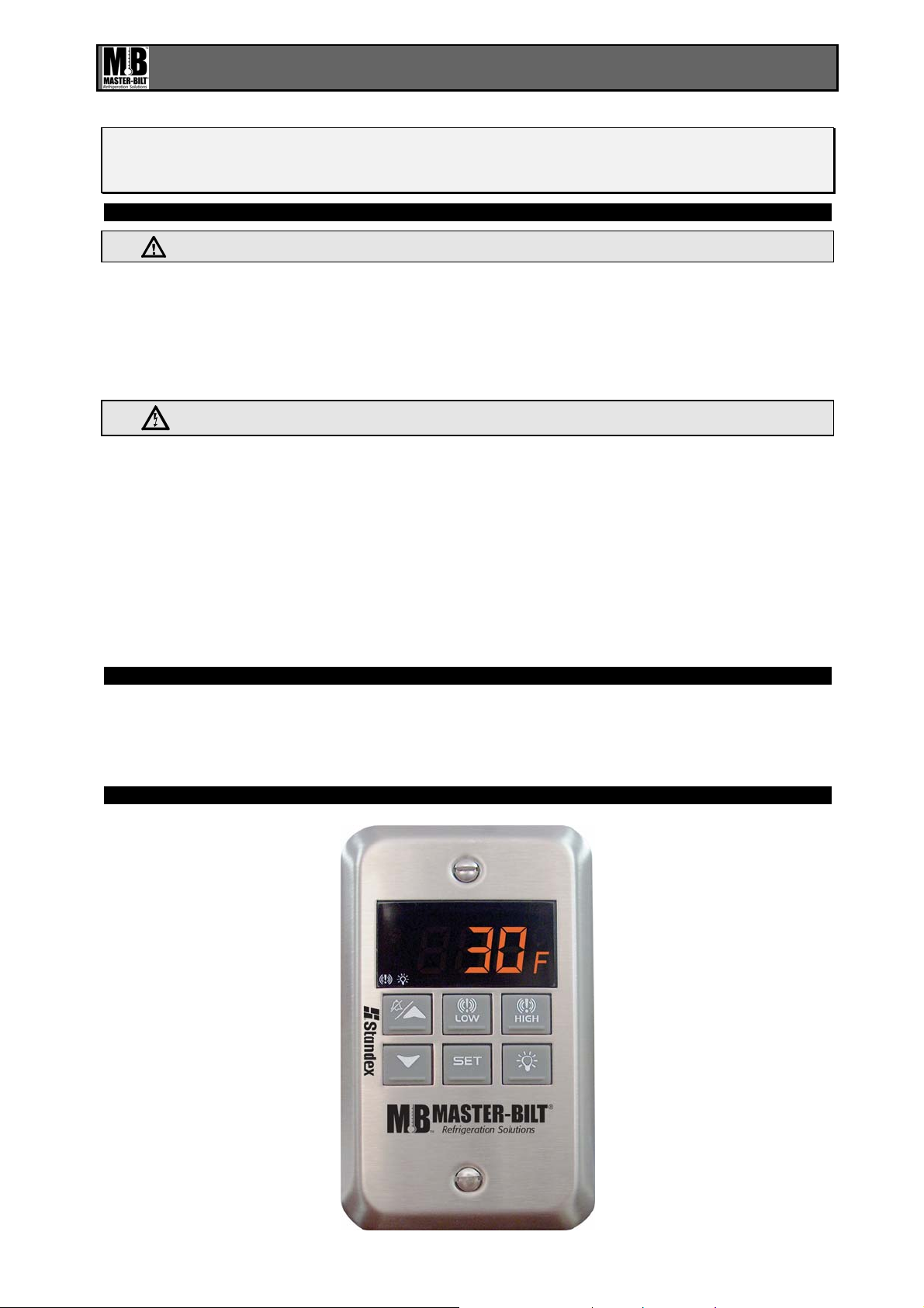
Walk-In Temp / Door /Alarm / Light Module
1. GENERAL WARNINGS
1.1 PLEASE READ BEFORE USING THIS MANUAL
• This manual is part of the product and should be kept close to the instrument for easy and quick
reference.
• The instrument shall not be used for purposes diff erent from those des cribed her eunder. It cannot be
used as a safety device.
• Check the application limits before proceeding.
1.2
• Check if the supply voltage is correct before connecting the instrument.
• Do not expos e to water or m oistur e: use the contro ller onl y with in the operati ng li m its avoiding sudd en
Temperature changes with high atmospheric humidity to prevent the formation of condensation.
• Warning: disconnect all electrical connections before performing any maintenance operation.
• Fit the probe where it is not damaged by the end-user. The instrument must not be opened.
• In case of failure or faulty operatio n send the instrument back to the distributor (see address) with a
detailed description of the fault.
• Consider the maximum current that can be applied to each relay (see Technical Data).
• Ensure that the wires for probes, loads and the po wer suppl y are separat ed an d far enough f rom eac h
other, without crossing or intertwining.
SAFETY PRECAUTIONS
2. GENERAL DESCRIPTION
Model XWA11V, 100x64 mm format, is a microprocessor based controller, suitable for temperature
monitoring in a walk-in cooler or freezer. It is provided with two (2) relay outputs to control lights and
signal an alarm. It is also provided with one (1) NTC probe input for temperature measurement. One (1)
output allows the user to program the parameter list with the “Hot Key”.
3. INTERFACE
Page 2
Operating Instructions for Master-Bilt Alarm/Light Module (19 -14009)
2
1598003200
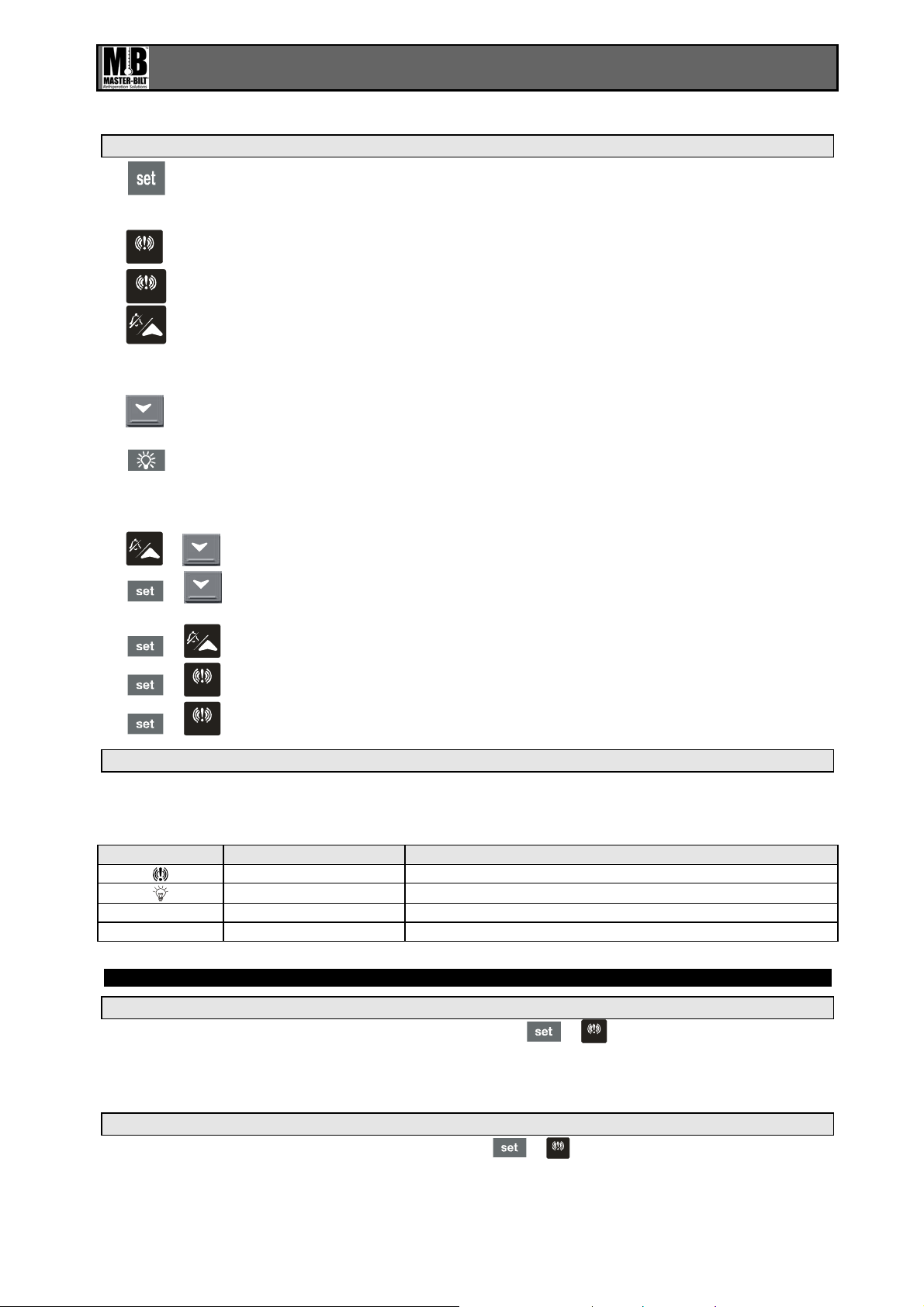
3.1 FRONT PANEL OPERATION
In Programming Mode press to select a parameter or to confirm an operation. *
Press and hold this key for more than 5 s to turn the controller OFF.
Press and hold this key for more than 1 s to turn the controller back ON.
Press to see the HIGH Temp ALARM (ALU param eter )
HIGH
Press to see the LOW Temp ALARM (ALL parameter)
LOW
In Programming Mode press to browse parameter codes.*
Press to increase the displayed value.
Press to mute the buzzer (+ relay) when an ALARM is happening.
Hot key programming: with the instrument on, insert the hot key and then press
the UP button.
In Programming Mode press to browse parameter codes.*
Press to decreases the displayed value.
Switch ON and OFF the light of the cold room
KEY COMBINATIONS: PR ES S SIMULTANEOUSLY
+
To lock and unlock the Keyboard.
+
To enter the Programming Mode.*
To exit the Programming Mode.
To enter a new value for the HIGH Temp ALARM (ALU).
HIGH
+
+
To enter a new value for the LOW Temp ALARM (ALL).
LOW
+
3.2 USE OF LEDS
Each LED function is described in the following table:
LED MODE Function
ON ALARM signaling
ON The light is on
°C ON Celsius degrees operation
°F ON Fahrenheit degrees operation
4. T ALARMS SETTING
4.1 HOW TO SET THE MIN TEMPERATURE ALARM
• To modify the minimum (LOW) Temp ALARM: hold the
minimum Temp alarm will be displayed.
• Change the value using the UP and DOWN keys.
• Press the SET key to confirm the new value and exit.
4.2 HOW TO SET THE MAX TEMPERATURE ALARM
• To modify the max (HIGH) Temp ALARM: hold the +
Temp alarm will be displayed.
• Change the value using the UP and DOWN keys.
• Press the SET key to confirm the new value and exit.
LOW
keys pressed for 3 s until the
+
HIGH
keys pressed for 3 s until the max
Page 3
Operating Instructions for Master-Bilt Alarm/Light Module (19 -14009)
3
1598003200
5. PROGRAMMING
5.1 HOW TO CHANGE A PARAMETER VALUE MAIN MENU
1. Enter the Programming Mode by pressing the SET and DOWN key for 3s ( and
start blinking).
2. Select the required parameter.
3. Press the “SET” key to display its value (now only the
LED is blinking).
4. Use “UP” or “DOWN” to change its value.
Press “SET” to store the new value and move to the following parameter.
To exit: Press SET + UP or wait 15 s without pressing a key.
NOTE: the set value is stored even when the procedure is exited, by waiting the time-out to expire.
5.2 THE HIDDEN MENU (PR2)
The hidden menu includes all the parameters of the instrument.
5.2.1 HOW TO ENTER THE HIDDEN MENU (PR2)
1. Enter the Programming Mode by pressing the Set + down key for 3s (
and
starts blinking).
2. When a parameter is displayed, release and re-press the SET + down for more than 7s.
3. The Pr2 label will be displayed immediately followed from the HY parameter. NOW YOU ARE IN
THE HIDDEN MENU.
4. Select the required parameter.
5. Press the “SET” key to display its value (Now only the
LED is blinking).
6. Use “UP” or “down” to change its value.
7. Press “SET” to store the new value and move to the following parameter.
To exit: Press SET + up or wait 15s without pressing a key.
NOTE: the set value is stored even when the procedure is exited by waiting the time-out to expire.
5.2.2 HOW TO MOVE A PARAMETER FROM THE HIDDEN MENU TO THE FIRST LEVEL AND
VICEVERSA
Each parameter present in the HIDDEN MENU can be removed or put into “THE FIRST LEVEL” (user
level) by pressing “SET + down”.
In HIDDEN MENU when a parameter is present in First Level the decimal point LED is on.
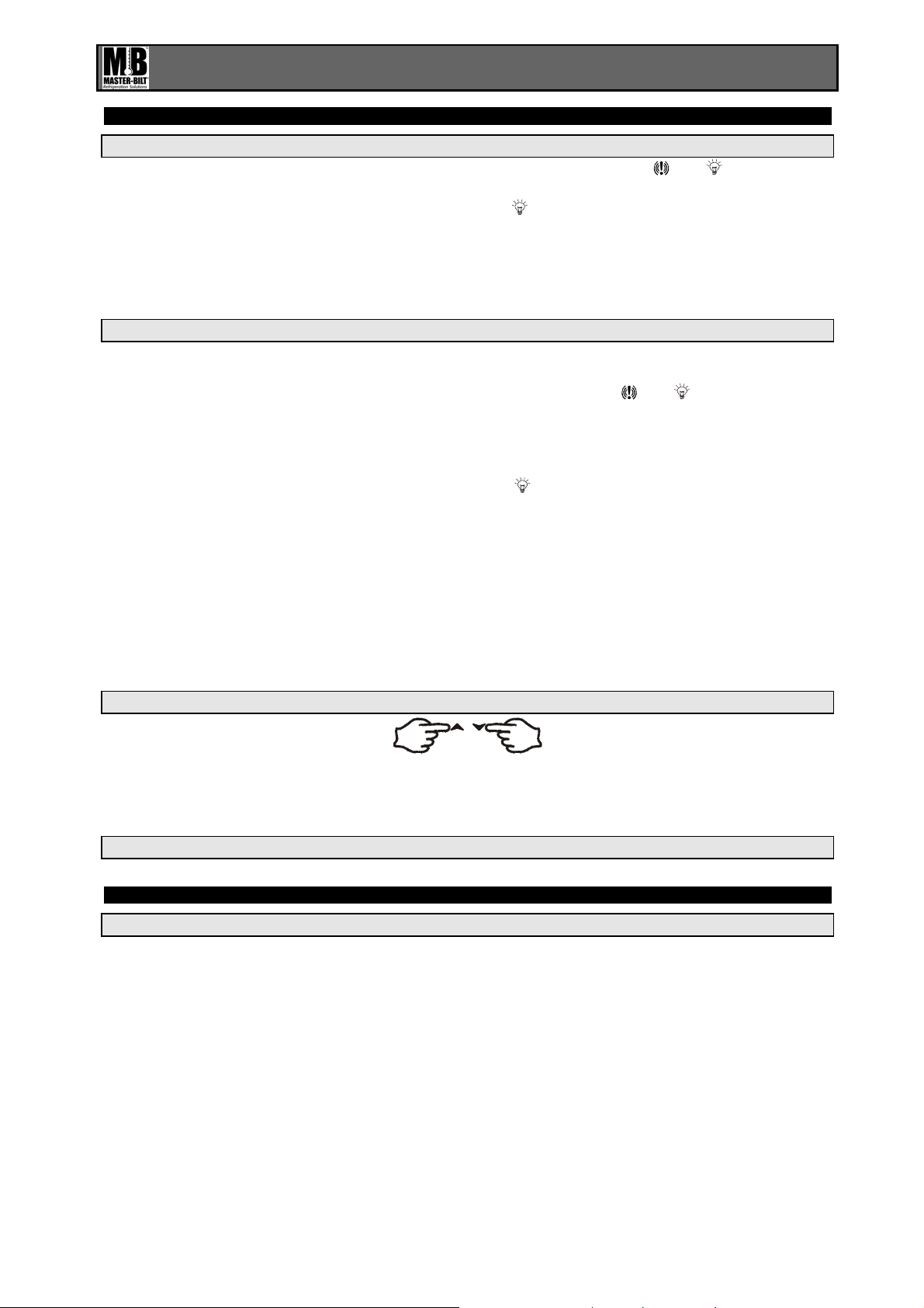
5.3 HOW TO LOCK THE KEYBOARD
1. Keep pressed for more than 3s the UP and DOWN keys.
2. The “POF” message will be displayed and the keyboard will be locked. At this point it will be possible
only to see the Set Point or the MAX o MIN Temp stored
3. If a key is pressed more than 3s the “POF” message will be displayed.
5.4 TO UNLOCK THE KEYBOARD
Keep pressed together for more than 3s the UP and DOWN keys.
6. LIGHT MANAGEMENT
6.1 TIMED REGULATION: I1L = Y
With i1L = y the light remains on at least for the LHt parameter.
The LHt timer is re-initialized every time the light button is pushed.
With LHt=0 the light remains on until the light button is pushed again.
The light is switched on every time one of the following conditions happens:
• the door is open (i1F = dor)
• the presence sensor is activated (i2F = LHt)
• the light button is pushed
The light is switched off when all the following conditions happen:
• the LHt timer is exhausted
• the door is closed (i1F = dor)
• the presence sensor is de-activated (i2F = LHt)
Page 4

Operating Instructions for Master-Bilt Alarm/Light Module (19 -14009)
4
1598003200
6.2 LIGHT BUTTON REGULATION: I1L = N
The light button has a higher priority than digital inputs therefore:
- if the light was switched on by button the digital input can not modify its status.
- if the light was switched on by digital input, the light button can modify its status.
7. INSTALLATION AND MOUNTING
7.1 MOUNTING OF XWA11V – PR10000
The XWA11V must be mounted on vertical
panel.
The Temp range allowed for correct
operation is 32 – 140°F. Avoid insta llati on is
places subject to strong vibrations, corrosive
gases, excessive dirt or humidity. The same
recommendations apply to probes. Let the air
circulate by the cooling holes.
8. ELECTRICAL CONNECTIONS
The instrument is provided with screw terminal blocks to connect cables with a cross section up to 2,5
2
mm
for the digital and analog inputs. Relays and power supply have a Faston connection (6,3mm). Heatresistant cables have to be used. Before connecting cables make sure the power supply complies with
the instrument requirements. Separate the probe cables from the power supply cables, from the outputs
and the power connections. Do not exceed the maximum current allowed on each relay and in case of
heavier loads use a suitable external relay.
N.B. Maximum current allowed for all the loads is 20A.
8.1 PROBE CONNECTIONS
The probe shall be mounted with the bulb upwards to prevent damages due to casual liquid infiltration. It
is recommended to place the thermostat probe away from air streams to correctly measure the average
room temperature.
9. USE OF THE PROGRAMMING “HOT KEY “
The Wing units can UPLOAD or DOWNLOAD the parameter list from its own E2 internal memory to the
“Hot Key” and vice-versa.
10. ALARM SIGNALS
Message Mode Cause Outputs
“P1” Flashing Thermostat probe failure Alarm output ON
PoF Flashing (3s) Keyboard locked Not changed
Pon Flashing (3s) Keyboard un-locked Not changed
“HA” Alternated with t Maximum T° alarm Alarm output ON;
“LA” Alternated with t Minimum T° alarm Alarm output ON;
“dA” Alternated with t Door switch alarm Alarm output ON;
“EA” Alternated with t External alarm Alarm output ON;
“PAn” Alternated with t Serious external alarm Alarm output ON;
dEF Alternated with t Defrost is running Not changed
The alarm message is displayed until the alarm condition is reset.
Page 5

Operating Instructions for Master-Bilt Alarm/Light Module (19 -14009)
5
Back up
1598003200
10.1 SILENCING BUZZER
Once the alarm signal is detected the buzzer can be silenced by pressing the UP key.
10.2 ALARM RECOVERY
Probe alarms : “P1” (probe1 faulty), “P2” ; they automatically stop 10s after the probe restarts normal
operation. Check connections before replacing the probe.
T° alarms “HA” and “LA” automatically stop as soon as the thermostat T° returns to normal values or
when the defrost starts.
Door switch alarm “dA” stops as soon as the door is closed.
External alarms “EAL”, “BAL” stops as soon as the external digital input is disabled.
11. TECHNICAL DATA
Housing: self extinguishing ABS
Case: face 100x64 mm; depth 45.5mm
Mounting: J-box or wall-mount option
Frontal protection: IP65
Connections: ¼” fastons for power, 18” fastons for probes and Digital Inputs
Power supply: 120Vac
± 10%, optional 230Vac ± 10%
Power absorption: 4VA max.
Display: 3 digits, red LED, 14,2 mm high.
Inputs: 1 NTC probe
Digital inputs: 2 free voltages
Relay outputs: Dry Contacts
Light: relay SPST 16A, 120Vac;
Alarm: relay SPST 8A, 120Vac
Other output: alarm buzzer
Data storing: on the non-volatile memory (EEPROM).
Measuring and regulation range:
NTC probe: -40÷110°C (-58÷230°F)
Resolution: 1 °F
Accuracy : ±1 °F
12. CONNECTIONS
Power supply: 230Vac
(9V DC)
D.I.1
D. I.2
Room
1 2 345678
8A
250V
16A 250V
Hot Key
11 12 13 14 15 16 17 18 19
L
Alarm C. C.Light
N
Supply 120V~
± 10% models, use the same terminals of the 120Vac version.
Page 6

Operating Instructions for Master-Bilt Alarm/Light Module (19 -14009)
6
1598003200
13. PARAMETER MAP
LABEL DESCRIPTION VALUE LEVEL RANGE
ot
CF
rES
UT
OnF
ALU
ALL
AFH
ALd
dAo
EdA
dot
LHt
doA
OA1
oA2
AOP
i1P
i1L
i1F
i2P
i2F
did
tbA
PbC
dP1
rEL
Ptb
Thermostat probe
calibration
T° measurement unit F Pr2 °C(0) - °F(1)
Resolution (only °C) in Pr2 dE(0) - in(1)
Display update 60 Pr2 0 <> 255 (s)
Off function enabling y Pr2 n(0) - Y(1)
High Tempalarm setting
Low Temp alarm setting
Temp alarm differential
Temp alarm delay 30 Pr1 0 <> 255 (min.)
Delay of Temp alarm at
start-up
Alarm delay at the end
of defrost
Delay of Temp alarm
after closing the door
Light timer 15 Pr1 0 <> 255 (min.)
Open door alarm delay 15 Pr1 0 <> 255 (min.)
First relay configuration ALr Pr2 ALr(0) - LHt(1) - OnF(2)
Second relay
configuration
Alarm relay polarity oP Pr2 OP - CL
Digital input 1 polarity oP Pr2 OP(0) - CL(1)
Door switch to turn light
ON
Digital input 1 operating
mode
Digital input 2 polarity cL Pr2 OP(0) - CL(1)
Digital input 2 operating
mode
Time interval/delay for
digital input alarm
Alarm relay disabling n Pr2 n(0) - Y(1)
Kind of probe ntc Pr2 PtC(0) - ntC(1)
Real T° Probe 1 Pr2 (probe value)
FW release Pr2 read only
Parameter map Pr2 read only
0 Pr2
50 Pr1
30 Pr1
2 Pr2
1.3 Pr2
30 Pr2
15 Pr2
LHt Pr2
y Pr2
dor Pr2
PA
n
Pr2
0 Pr2
[-12,0°C <> 12,0°C] [-
21°F <> 21°F]
°C[ ALL <> 150,0°] °F[
ALL <> 302°]
°C[ -50.0° <> ALU] °F[-
58 <> ALU]
[0,1°C <>25,5°C] [1°F
<> 45°F]
0 <> 24H0(144)
0 <> 255 (min.)
0 <> 255 (min.)
ALr(0) - LHt(1) - OnF(2)
n(0) - Y(1)
EAL(0) - dor(1) - dEr(2)
- LHt(3)
EAL(0) - Pan(1) -
dFr(2) - LHt(3)
0 <> 255 (min.)
Page 7

Operating Instructions for Master-Bilt Alarm/Light Module (19 -14009)
7
1598003200
14. PARAMETER LIST
Ot Thermostat probe calibration: (-12.0
÷12.0°C/ -21÷21°F) allows to adjust possible offset of the
thermostat probe.
CF T measurement unit: °C = Celsius; °F = Fahrenheit. When the measurement unit is changed the
Set Point and the values of some parameters have to be modified.
rES Resolution (for °C): (in = 1°C; dE = 0.1 °C) allows decimal point display.
Ut Display update: The time delay of the T readout (0÷255s)
onF Off function enabling: n = off function disabled; y = off function enabled;
ALU High T° alarm setting: (ALL
÷ 150°C or 302°F);
when this T° is reached and after the ALd delay time the HA alarm is enabled.
ALL Low T° alarm setting: (- 50°C or -58°F
÷ ALU)
when this T° is reached and after the ALd delay time, the LA alarm is enabled,.
AFH T° alarm differential: (0,1÷25,5°C; 1÷45°F) differential for T° alarm Set Point and fan regulation Set
Point, always a positive value
ALd T° alarm delay: (0÷255 min) time interval between the detection of an alarm condition and the
corresponding alarm signali ng.
dAO Delay of T° alarm at start-up: (0min÷23h 50min) time interval between the detection of the T°
alarm condition after the instrument power on and the alarm signaling.
EdA Alarm delay at the end of defrost: (0
÷255 min) Time interval between the detection of the T° alarm
condition at the end of defrost and the alarm signaling.
dot Delay of T° alarm after closing the door: (0
÷255 min) Time delay to signal the T° alarm
condition after closing the door.
LHt Light timer: (0-255 min) The time the light will stay on after pressing the light switch on the
keyboard.
doA Open door alarm delay:(0÷255 min) delay between the detection of the open door condition and its
alarm signaling: the flashing message “dA” is displayed.
oA1 First relay configuration: (14-15): ALr = alarm; LHt = light; onF = on/off relay
oA2 Second relay configuration: (14-16): ALr = alarm; LHt = light; onF = on/off relay
AOP Alarm relay polarity: cL = closing contacts; oP = opening contac ts.
i1P Digital input 1 polarity (1-2): CL : the digital input is activated by closing the contact;
OP the digital input is activated by opening the contact
i1L Door switch to turn light ON(1-2): (y / no) To turn the light ON automatically when the door is
open. The light will turn off based on LHt . Keyboard switch must be turned ON first.
i1F Digital input 1 operating mode(1-2): EAL = external alarm; dor = door switch; dFr = A defrost is
running; LHt = keep light ON (signal from occupancy sensor) override LHt.;
i2P Digital input 2 polarity (1-3): CL : the digital input is activated by closing the contact;
OP the digital input is activated by opening the contact
i2F Digital input 2 operating mode: configure the digital input function:
EAL = External alarm;
PAn =Panic alarm;
dFr = A defrost is running;
LHt = Keep light ON (signal from occupancy sensor) override LHt.
did Time interval/delay for digital input alarm:(0
÷255 min.) If I2F=EAL or PAn (external alarms), “did”
parameter defines the time delay between the detection and the successive signaling of the alarm.
tbA Alarm relay & Buzzer disabling: (y ; no)
Pbc Type of probe (PTC, NTC)
dP1 Probe 1 T
rEL Software release for internal use.
Ptb Parameter table code: read only.
15. PARTS LIST
M/B Part Number Description
19-14009 WI therm, alarm, panic light, contl. #XWA11V-4N1F0
19-14012 PROBE, 18NB-NTC-1.5M, (5')
19-14013 PROBE, 18NB-NTC-1.5M, (50')
19-14014 PROBE, 18NB-NTC-1.5M, (75')
For more information, please contact our Technical Service Dept.
@ 1-800-684-8988
 Loading...