

Page 1

MA206 / MAW115D
User’s manual
Pol.Ind.Norte-Perpinyà,25
08226 TERRASSA (Barcelona-SPAIN)
info@master-audio.com
www.master-audio.com
Nov 2008
Page 2

Amate Electroacústica,s.l.
MA206/MAW115.Version 1.3 Nov 08
2
Safety Instructions
1. All the safety and operation instructions should be read before this product is
operated.
2. The exclamation point within an equilateral triangle is intended to alert the user of
the presence of internal components whose substitution may affect safety.
3. The lightning flash with arrowhead symbol within an equilateral triangle is intended
to alert the user of the presence of uninsulated dangerous voltage, that may
constitute a risk of electric shock to people.
4. This product should not be exposed to rain or moisture. Do not use it, for example,
near a swimming pool, water fountain or any liquid sources.
5. Clean only with a dry cloth.
6. This product should be situated so that its location does not interfere with its proper
ventilation.
7. Do not install near heat sources such as radiators or other devices which produce
heat.
8. This equipment should be serviced only by qualified service personnel when:
A. The power-supply cord or the plug has been damaged; or
B. Objects have fallen or liquid has been spilled onto it; or
C. This product does not appear to operate normally; or
D. This product has been exposed to rain; or
E. The chassis is damaged.
9. Unplug this product during lightning storms or when unused for long periods of
time.
10. Do not suspend the cabinet from the handles.
CAUTION
RISK OF ELECTRIC SHOCK
DON’T OPEN
To reduce the risk of fire or electric shock do
not expose this equipment to rain or moisture
WARNING:
Page 3

Amate Electroacústica,s.l.
MA206/MAW115.Version 1.3 Nov 08
3
1.INTRODUCTION
1.1.General
Amate Electroacústica, s.l. would like to thank you for your confidence in our new
MA and MAW Series, specially designed for Line Array configurations.
The accumulated experience of more than 30 years in the design of acoustic
cabinets and amplifiers, together with the application of the most advanced
technology and transducers, have allowed this series to become the optimal and
ideal solution for a wide range of situations, specially those which require high levels
of sound pressure and a control of vertical coverage. Stadiums, theatres, big events,
etc... will become the perfect places for its use.
We suggest you carefully read the following instructions in order to obtain the best
results in performance.
1.2.What is a line array?
The trend in sound reinforcement has been to increase both the sound pressure level
(SPL) and the size of the audience to be covered. This leads to an increase in the
number of cabinets and, as a result of this, an increase in the total size and weight.
A line array is a group of independent sound sources which are vertically stacked in
order to transform the spherical wavefronts generated by individual sources into a
single flat wavefront.
Fig.1. Wavefield interference for different wavefronts.
To carry out effectively arraying individual sound sources the system must follow the
acoustic coupling conditions based on the wavelength, the shape of each source, the
surface area of each transducer and the relative source separation.
An assembly of individual sound sources arrayed with regular separation between the
sources on a plane or curved continuous surface is equivalent to a single sound
source having the same dimensions as the total assembly if the following conditions
are fulfilled:
Page 4
Amate Electroacústica,s.l.
MA206/MAW115.Version 1.3 Nov 08
4
1) The step of source separation, defined as the distance between the acoustic
centres of the individual sources, is smaller than half the wavelength over the
bandwidth of operation.
d<= λ/2
It is easy to fulfil this first condition for the low and mid frequencies. For example, two
7" loudspeakers that are separated by 17 cm will reproduce a cylindrical wave up to
1015 Hz.
This condition is difficult to be fulfilled for the high frequencies, as their wavelengths
are too small to make the adjacent acoustic centres any smaller than λ/2. Here comes
the second "arrayability" criterion.
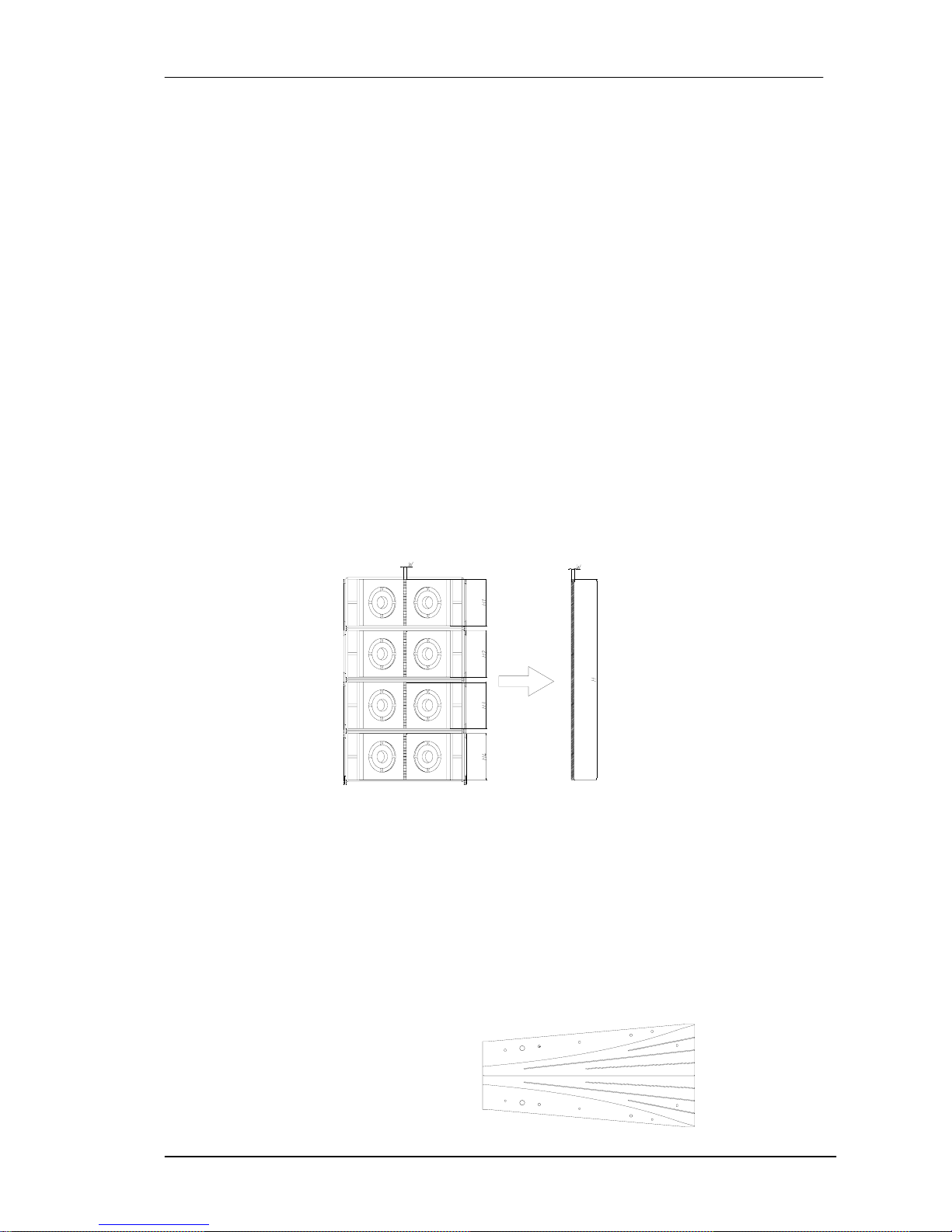
2) The wavefronts generated by the individual sources are planar and the combined
surface area of the sources fills at least 80% of the total target surface area:
H1·W + H2·W+.....+Hn·W >=0.8·H·W
This is achieved by using waveguides, which are coupled to the compression drivers
output. We achieve flat wavefronts with a constant phase. By vertically assembling
these waveguides we fulfil the second criterion of line array construction.
Fig.2. Second criterion of "arrayability"
3) The deviation from a flat wavefront must be less than λ/4 at the highest operating
frequency (this corresponds to less than 5 mm curvature at 16kHz).
This third condition can be explained through our property waveguide. Thanks to some
complex mathematical calculations we have obtained an aluminium component which
is able to adapt the circular section of the compression driver to a rectangular section,
getting on-phase waves at the end of the guide. This flat wavefront is ideal for vertical
configurations.
Fig.3. High frequency waveguide
Page 5
Amate Electroacústica,s.l.
MA206/MAW115.Version 1.3 Nov 08
5
Sound engineers use line arrays to obtain narrow directivities on the vertical plane. For
configurations with many cabinets (big height) and at high frequencies it is not unusual
to achieve narrow angles- in some cases they may be grade fractions. This can be
useful in venues where both a high sound pressure level and long throw are required;
nevertheless, this means less coverage of the audience area.
It is sometimes useful to achieve an asymmetrical coverage pattern on the vertical
plane, which can be obtained by aiming some of the cabinets through their hinging
points. We are now ready to define the last two criteria of "arrayability".
4) For curved arrays, the tilt angles should vary in inverse proportion to the listener
distance (this is geometrically equivalent to shaping variable curvature arrays to
provide equal spacing of individual element impact zones).
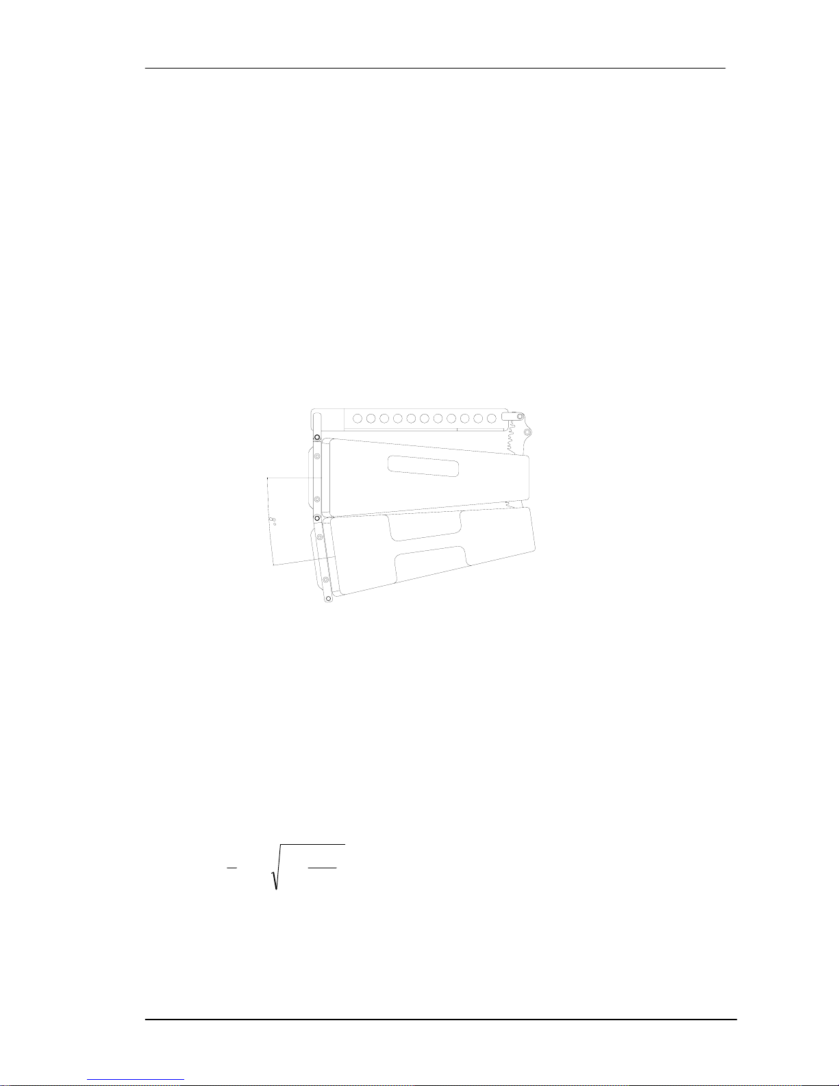
5) There are limits given the vertical size of each cabinet and their relative tilt angles.
In our case the maximum angle between cabinets is 8º .
Fig.4. Tilt angle between cabinets (8º maximum)
1.3.Fresnel Region (Near Field) and Fraunhofer Region (Far Field)
If our system is able to fulfil the previous conditions it will produce cylindrical waves to
a maximum frequency. The wave will be flat up to a certain distance where it will start
to become spherical (depending on the frequency and the size of the array).
The limit distance between the zone of cylindrical waves (Fresnel) and spherical
waves (Fraunhofer) can be calculated through the following formula
2
2
3
1
1
2
3
⎟
⎟
⎠
⎞
⎜
⎜
⎝
⎛
−=
Hf
fHdc
where
dc= limit distance between near field and far field (in metres)
H = height of the array (in metres)
f= frequency (in kHz)
Page 6
Amate Electroacústica,s.l.
MA206/MAW115.Version 1.3 Nov 08
6
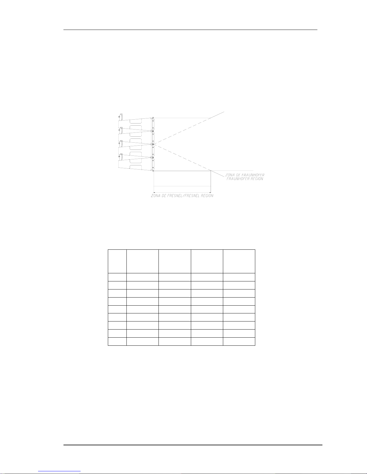
In the near field region (Fresnel), the wavefront is cylindrical and waves only expand
on the horizontal plane (90º in MA-206). The height of the wavefront is, in this case,
the total height of the array.
In the far field region (Fraunhofer), the wavefront is spherical and expands both on
the horizontal and vertical planes. The horizontal coverage is 90º and the vertical
coverage is defined by the frequency and the height of the array.
Fig.5. Limits of Fresnel-Fraunhofer Regions
We can create a chart with some of the basic configurations and their performance
regarding wave propagation.
Freq
(Hz)
4x
MA206
dc(m)
8x
MA206
dc(m)
12x
MA206
dc(m)
16x
MA206
dc(m)
100
Spherical Spherical Spherical Spherical
125
Spherical Spherical Spherical 0.72
250
Spherical 0.36 1.48 2.95
500
0.18 1.47 3.54 6.43
1k
0.74 3.21 7.34 13.13
2k
1.6 6.56 14.82 26.33
4k
3.28 13.2 29.7 52.83
8k
6.6 26.4 59.34 105.7
10k
8.25 33 74.31 132.12
Fig.6. d
c
Calculation
A 12-cabinet array has a near field extending to 15 metres at 2kHz. Beyond this
distance the wavefront will be spherical.
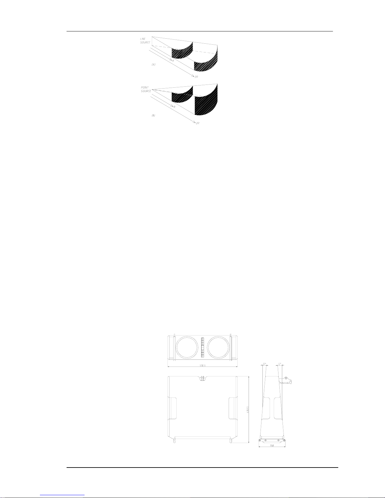
In the first zone (Fresnel), sound pressure loss is of 3 dB per doubling of distance,
whereas in the second zone (Fraunhofer) the loss is 6 dB. In long throw and high
SPL configurations it is very important to produce cylindrical waves.
Page 7
Amate Electroacústica,s.l.
MA206/MAW115.Version 1.3 Nov 08
7
Fig.7.Cylindrical wave (A) vs Spherical wave (B)
(A) : -3 dB / doubling of distance
(B) : -6 dB / doubling of distance
2. MA-206 SYSTEM DESCRIPTION
Amate Electroacústica offers the basic set of the MA-206 System which includes:
3 units of the MA-206/P
1 unit of the MA-206/D
This last model is the main unit and includes all the necessary electronics to feed
three MA-206/P units.
Both models include the same electroacoustic components. They are 2-way units
that use two 6.5" for the low-mid frequencies and one 1" compression drivers (44mm
voice coil) coupled to property waveguides for the high frequencies. We also
introduce a low frequency reinforcement cabinet called MAW-115 in its active with
DSP version (MAW-115/D).
2.1.Front design
The MA-206 shape is "trapezoidal-flat". The "baffles" are flat-shaped and the cabinet
has a trap angle of 2 x 5º.
Fig.8. Dimensions of MA-206
Page 8

Amate Electroacústica,s.l.
MA206/MAW115.Version 1.3 Nov 08
8
2.2. 6.5" Neodymium Woofers
The low-mid way includes two 6.5" Neodymium woofers, with 1.5" aluminium voice
coil
2.3. 1" Compression drivers with waveguide
The high frequency way includes one 1" compression drivers coupled to planar
waveguides. Thanks to their Pure Titanium 44mm diaphragm we achieve an
extremely good and clear sound, better than any other option.
The accurate design of our waveguide transforms the spherical waves produced by
the driver into planar waves, while transversal stationary waves are also avoided
within the audio field (up to 20kHz).
2.4.Finish
In its continuous research into offering the best product at all levels, the MA-206 has
been made of vibration and moisture-resistant birch plywood. All cutting and milling
work, as well as drilling operations, has been developed by computerized numeric
control machinery (CNC) which allows us to assure perfect and accurate assembly.
The black finish, which uses totally ecological water-based acrylic resin paint, provides
an excellent external protection.
We also include a 1.5mm steel Front grille with 5mm acoustically transparent foam.
Each unit incorporates rigging for safe, easy and quick flying or stacking.
2.5. MA-206/D System
D=DSP version of MA-206 with independent amplification on each way and internal
processing through DSP included. Transducers and waveguides are those explained
in 2.2 and 2.3.
The Class D amplification modules are 1000 W for the low way and 500 W for the high
way. Their high efficiency (almost 90%) allows their location on the lower panel without
the necessity of forced cooling. We eliminate any fan or any other auxiliary device
which may fail because of extra mechanical work.
The DSP control software allows:
• Parametric equalizations
• Delays
• Gain control for each way
• Crossovers up to 24 dB/Oct
• Limiters for each way
The adjustments can be done through a rear screen placed on each MA-206/D or
through PC with RJ45 connectors.
Page 9
Amate Electroacústica,s.l.
MA206/MAW115.Version 1.3 Nov 08
9
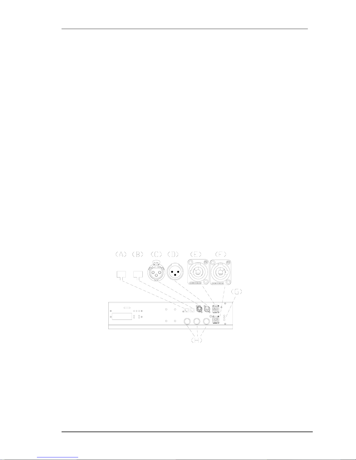
2.5.1.Rear connections
Each unit of MA-206/D includes a Rear Panel with the following items:
A) RJ45 INPUT : PC Signal Input
B) RJ45 LINK : PC Link Signal
C) INPUT SIGNAL : Balanced XLR input signal connector
1= Shield 2= Live 3= Return
D) LINK INPUT SIGNAL : Balanced XLR connector for paralleling several units, which
will share the same input.
1= Shield 2= Live 3= Return
E) AC INPUT : Input PowerCon connector.
F) AC STACKING OUTPUT : PowerCon Output connector to feed a secondary
cabinet.
G) AC MAINS LED INDICATORS
ON: Lights when AC input is correct.
STAND BY: Lights during power-up sequence.
OVERVOLTAGE PROTECTION: Lights if AC input voltage is over 250VAC. The
system protects itself and will not start up until AC level is correct.
H) SIGNAL OUT : Signal output to feed 3 passive units of MA-206/P.
Fig.9. Connections panel for MA-206/D
2.6. MA-206/P
P=Passive version of MA-206 feed by a MA206/D. Transducers and waveguides are
those explained in 2.2 and 2.3.
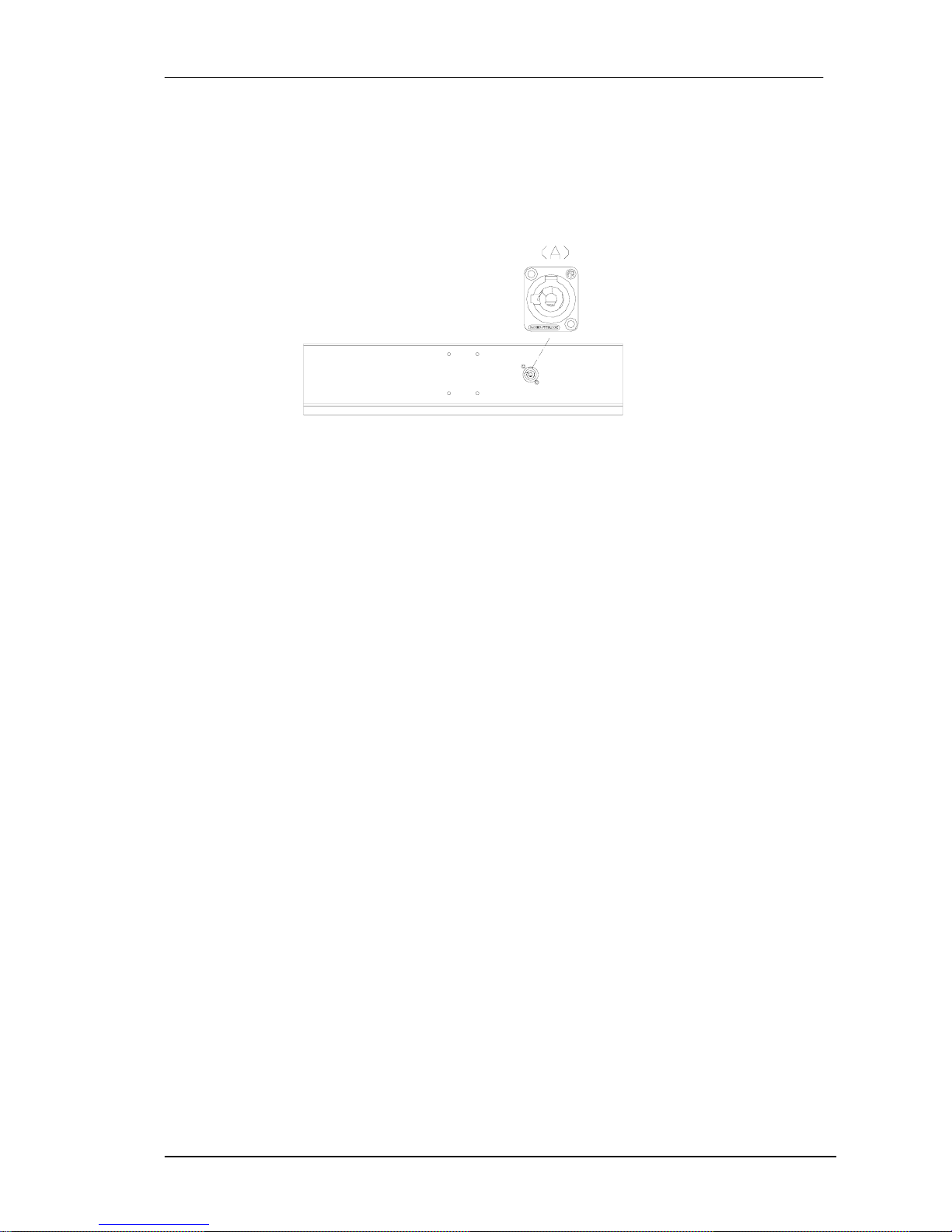
2.6.1. Rear connections
Each unit of MA-206/P includes a Rear Panel with the following items:
Page 10
Amate Electroacústica,s.l.
MA206/MAW115.Version 1.3 Nov 08
10
A) SPEAKON INPUT: Input signal:
PIN +1 : Woofer + (Positive)
PIN -1 : Woofer - (Negative)
PIN +2: Driver + (Positive)
PIN -2: Driver - (Negative)
Fig.10. Connections panel for MA-206/P
3.MAW-115 SYSTEM DESCRIPTION
Amate Electroacústica offers the MAW-115/D: Active version with DSP control
This model is a Bass Reflex unit that contains one 15" Neodymium Woofer.
3.1. 15" Neodymium Loudspeakers
The 15" transducers used, which are probably the best ones on the current market
with these features, offer a clean, undistorted low frequency reproduction at very high
sound pressure levels. This low distortion and unmatched quality are further and
significantly improved by the double demodulating rings (DDR) embedded in the pole
piece of the magnetic structure. These are designed to dramatically reduce the
intermodulation and third order distortion while also improving transient response.
Excellent heat dissipation is achieved by incorporating external magnetic configuration.
3.2.Finish
The MAW-115D has been made of vibration and moisture-resistant birch plywood. All
cutting and
milling work, as well as drilling operations, has been developed by computerized
numeric control machinery (CNC) which allows us to ensure perfect and accurate
assembly.
The black finish, which uses totally ecological water-based acrylic resin paint, provides
an excellent external protection
We also include a 1.5mm black-painted steel grille with acoustically transparent foam
on the front side.
Page 11
Amate Electroacústica,s.l.
MA206/MAW115.Version 1.3 Nov 08
11
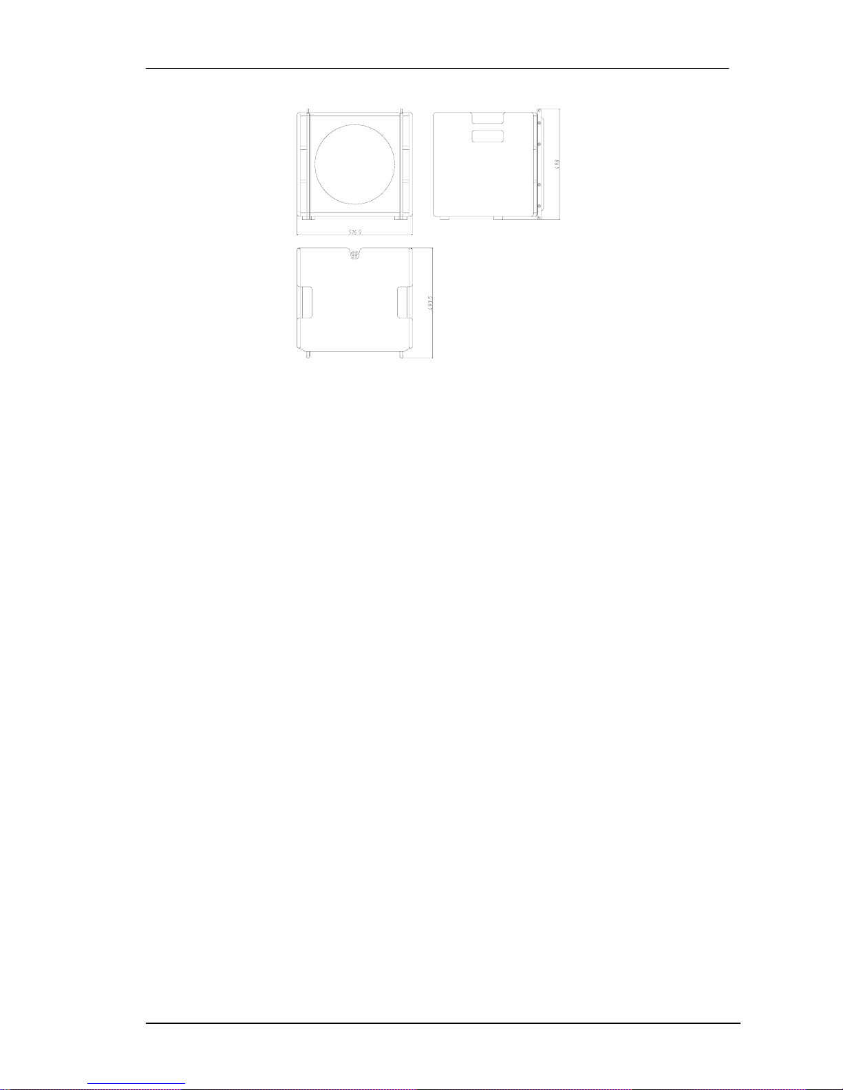
Fig.11. Dimensions of MAW-115
Each unit incorporates rigging on its side for safe, easy and quick flying or stacking.
3.3. MAW-115/D System
D=DSP version of MAW-115 with in-built amplification and internal processing through
DSP included.
The Class D amplification module is 1000 W. Their high efficiency (almost 90%)
allows their location on the rear panel without the necessity of forced cooling. We
eliminate any fan or any other auxiliary device which may fail because of extra
mechanical work.
The DSP control software allows:
• Parametric equalizations
• Delays
• Gain control
• Crossovers up to 24 dB/Oct
• Limiters
The adjustments can be done through a rear screen placed on each MAW-115/D or
through PC with RJ45 connectors.
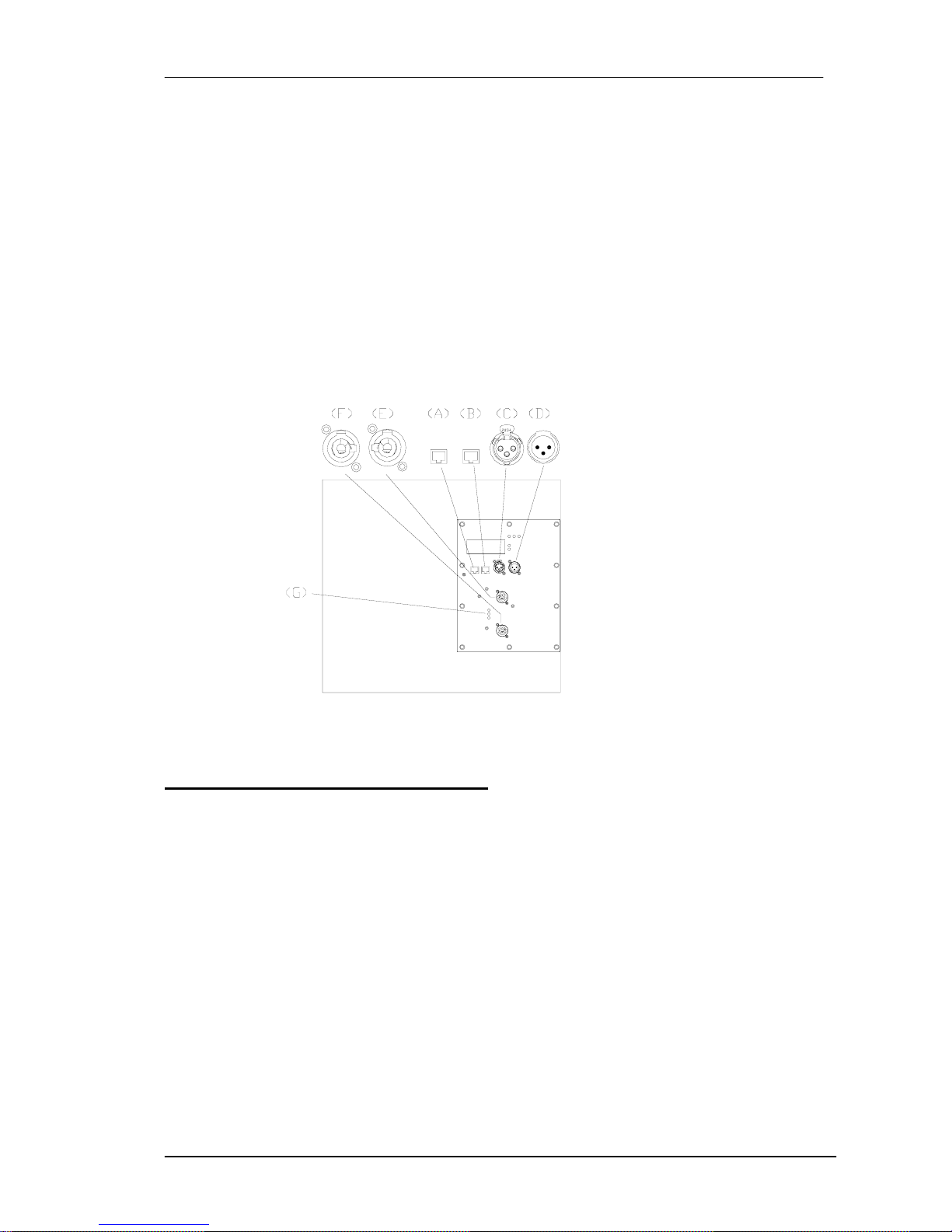
3.3.1.Rear connections
Each unit of MAW-115/D includes a Rear Aluminium Panel with the following items:
A) RJ45 INPUT : PC Signal Input
B) RJ45 LINK : PC Link Signal
C) INPUT SIGNAL : Balanced XLR input signal connector
1= Shield 2= Live 3= Return
Page 12
Amate Electroacústica,s.l.
MA206/MAW115.Version 1.3 Nov 08
12
D) LINK INPUT SIGNAL: Balanced XLR connector for paralleling several units, which
will share the same input.
1= Shield 2= Live 3= Return
E) AC INPUT : Input PowerCon connector.
F) AC STACKING OUTPUT: PowerCon Output connector to feed a secondary
cabinet.
G) AC MAINS LED INDICATORS
ON: Lights when AC input is correct.
STAND BY: Lights during power-up sequence.
OVERVOLTAGE PROTECTION: Lights if AC input voltage is over 250VAC. The
system protects itself and will not start up until AC level is correct.
Fig.12. Connections panel for MAW-115/D
4.MAW-215/2K SYSTEM DESCRIPTION
Amate Electroacústica offers one version of its MAW-215/2K Low frequency
reinforcement System.
MAW-215/D/2: Active version with DSP control
It includes two 15" Neodymium Woofers and they are acoustically controlled by the
volume of their three chambers. Despite its compact size, we obtain an excellent
performance with very low levels of distortion.
4.1. 15" Neodymium Loudspeakers
The 15" transducers used, which are probably the best ones on the current market
with these features, offer a clean, undistorted low frequency reproduction at very high
sound pressure levels. This low distortion and unmatched quality are further and
significantly improved by the double demodulating rings (DDR) embedded in the pole
piece of the magnetic structure. These are designed to dramatically reduce the
Page 13
Amate Electroacústica,s.l.
MA206/MAW115.Version 1.3 Nov 08
13
intermodulation and third order distortion while also improving transient response.
Excellent heat dissipation is achieved by incorporating external magnetic configuration.
4.2.Finish
The MAW-215D/2K has been made of vibration and moisture-resistant birch plywood.
All cutting and milling work, as well as drilling operations, has been developed by
computerized numeric control machinery (CNC) which allows us to ensure perfect and
accurate assembly.
The black finish, which uses totally ecological water-based acrylic resin paint, provides
an excellent external protection
We also include a 2mm black-painted steel grille with acoustically transparent foam on
the front side.
Each unit incorporates rigging on its side for safe, easy and quick flying or stacking.
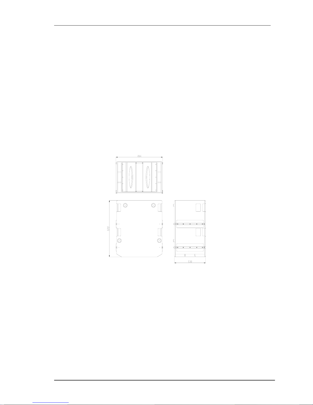
Fig.13. Dimensions of MAW-215D/2K
4.3. MAW-215/D/2K System
D=DSP version of MAW-215 with in-built amplification and internal processing through
DSP included.
The Class D amplification modules are 1000 W (two units, total 2000 W). Their high
efficiency (almost 90%) allows their location on the rear panel without the necessity of
forced cooling. We eliminate any fan or any other auxiliary device which may fail
because of extra mechanical work.
The DSP control software allows:
Page 14
Amate Electroacústica,s.l.
MA206/MAW115.Version 1.3 Nov 08
14
• Parametric equalizations
• Delays
• Gain control
• Crossovers up to 24 dB/Oct
• Limiters
The adjustments can be done through a rear screen placed on each MAW-215/D/2K
or through PC with RJ45 connectors.
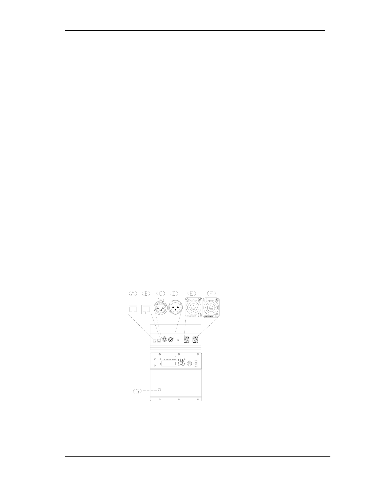
4.3.1.Rear connections
Each unit of MAW-215/D includes a 4mm Rear Panel with the following items:
A) RJ45 INPUT : PC Signal Input
B) RJ45 LINK : PC Link Signal
C) INPUT SIGNAL : Balanced XLR input signal connector
1= Ground 2= Live 3= Return
D) LINK INPUT SIGNAL : Balanced XLR connector for paralleling several units, which
will share the same input.
1= Ground 2= Live 3= Return
E) AC INPUT : Input PowerCon connector.
F) AC STACKING OUTPUT : PowerCon Output connector to feed a secondary
cabinet.
G) LED OVERVOLTAGE
Fig.14. Connections panel for MAW-215/D/2K
Page 15
Amate Electroacústica,s.l.
MA206/MAW115.Version 1.3 Nov 08
15
5.-SYSTEM CONNECTIONS
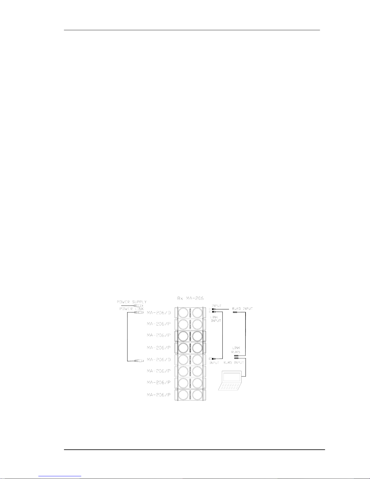
As an example, let us start with an 8 MA-206 cabinet configuration (including 2 units
of MA-206/D and 6 units of MA-206/P). All the rest of configurations may be deduced
from this base system.
Each set includes a FACTORY PRESET which can be modify through the control
software or the in-built rear digital screen.
A sound system must be switched on sequentially. Firstly switch on the sound
sources such as CD players. Then, the mixer and finally the self-powered cabinets. If
you are using several units it is recommended that you switch them on sequentially
one at time.
If you are not using MA-206 in combination with low frequency reinforcement units,
plug the output of mixer into the first unit of MA-206/D Input. (Fig.9. INPUT SIGNAL
(C)).
Daisy chain the first unit of MA-206/D with the second unit of MA-206/D through
LINK INPUT SIGNAL connectors.
Feed the first unit of MA-206/D through AC INPUT connector (Fig.9.(E)). and simply
daisy chain the second unit of MA-206/D through AC STACKING OUTPUT.
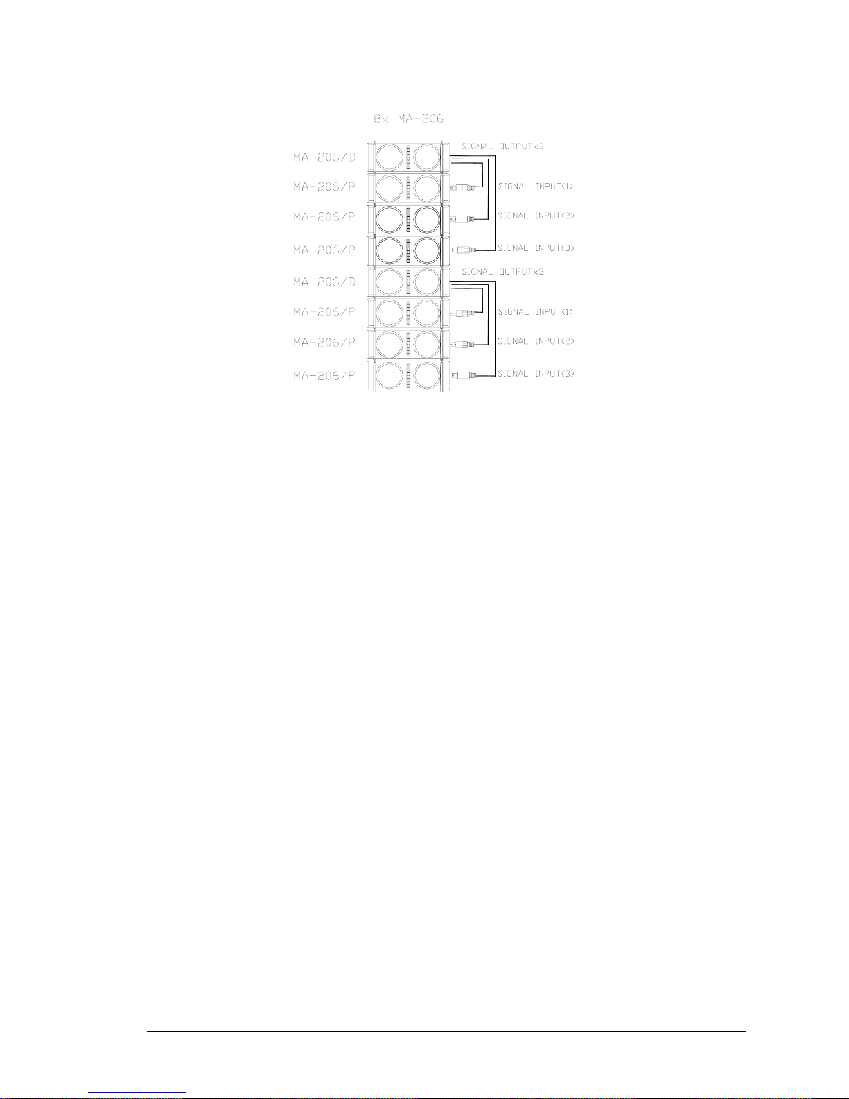
Connect the 3 signal outputs from the MA-206/D (Fig.9.(H)) to the Speakon inputs of
each MA-206/P.
For the DSP control via PC/Laptop simply connect the PC output to the RJ45 INPUT
(Fig.9.(A)) of the first MA206/D unit and daisy chain the signal to the second of
MA206/D unit through RJ45 LINK (Fig.9.(B)).
Page 16
Amate Electroacústica,s.l.
MA206/MAW115.Version 1.3 Nov 08
16
Fig.15. 8xMA-206 Connections
6.FLYING SYSTEM
Flying an MA system is easy, fast and secure. To perform any operations related to
flying the system, read the present document, and act on the warnings and advice
given.
Only experienced installers with adequate knowledge of the system and local safety
regulations should fly speaker cabinets.
It is the user's responsibility to ensure that the systems to be flown and the flying
accessories (such as chains, eyebolts, lock pins...) comply with state and local
regulations. They should be regularly inspected and replaced if in doubt.
When flying enclosures from ceiling support structures, extreme care should be taken
to assure the load bearing capabilities of the structures. Do not fly systems from
unsafe structures.
All flying accessories that are not supplied by Amate Electroacústica are the user's
responsibility. Use at your own risk.
Remember that no risks should be taken with regards to public safety.
6.1.Description
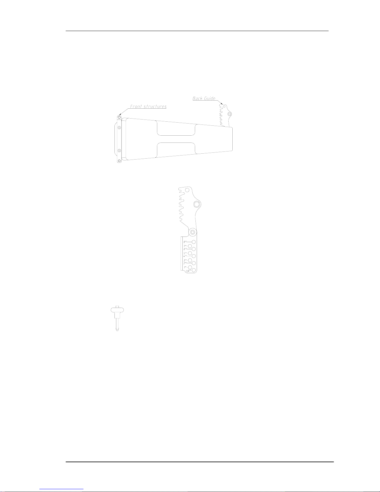
Each MA-206 cabinet includes flying structures on the front-lateral sides and on the
back side. These structures are manufactured from stainless steel; they are affixed
with special crop resistant screws. The front structures are used to vertically join the
cabinets; the back structures are used to vertically join the cabinets and to tilt them.
Angles can be changed from 0º to 8º. To safely lock the guides, the lock pins
supplied must be used.
Page 17
Amate Electroacústica,s.l.
MA206/MAW115.Version 1.3 Nov 08
17
To tilt the cabinets, the back structures and the back guide must be used.
The available degrees are 0º, 1º, 2º, 3º, 4º, 5º, 6º, 7º and 8º.
To fix the guides to the holes, highly resistant 8mm pins are used with ball safety
lock.
Fig.16. Flying structures (general view)
Fig.17. Back guide with graduation
Fig.18. Ball Lock Pins
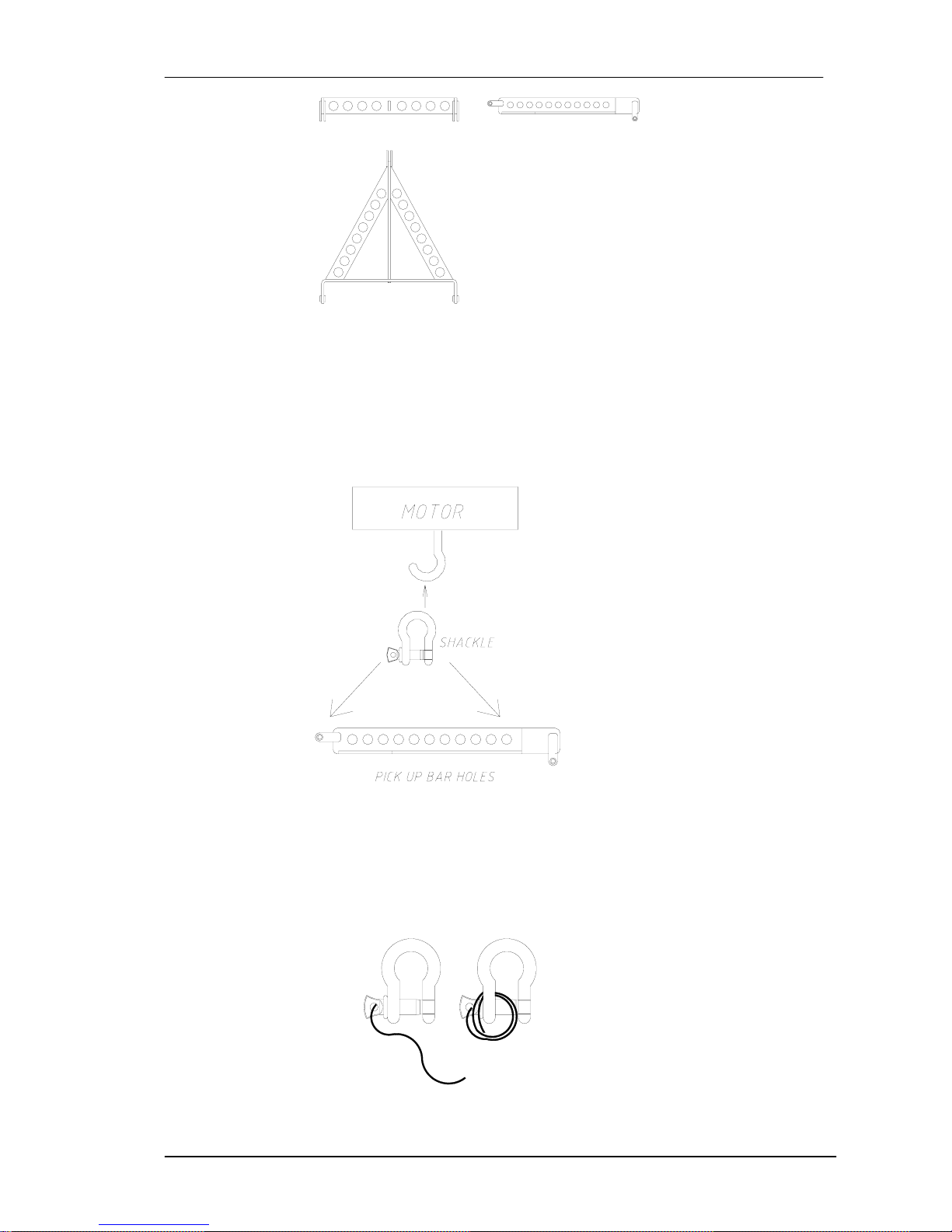
The flying Frame is made from stainless-steel and is designed to handle great loads.
It includes a centre and lateral bars to reinforce the whole structure. The centre bar
has a series of holes that provide a pickup point for the steel chain slings or the
hoists. The pickup point chosen will determine the tilt angle of the whole array
system.
Page 18
Amate Electroacústica,s.l.
MA206/MAW115.Version 1.3 Nov 08
18
Fig.19. Flying Bumper
A shackle is included on the Flying Bumper Kit. It can be fitted into any of the centre
bar holes (depending on the gravity centre of the configuration). The shackle can be
also hung on the elevation motor of the system.
Fig.20. Flying structure
We recommend the use of a safety cable on the shackles' hole. (see Fig.23). You
should coil the cable around the shackle to avoid any incident in case of unscrewed
guides.
Fig.21. Safety cable for shackle
Page 19
Amate Electroacústica,s.l.
MA206/MAW115.Version 1.3 Nov 08
19
6.2. MA-206 Flying
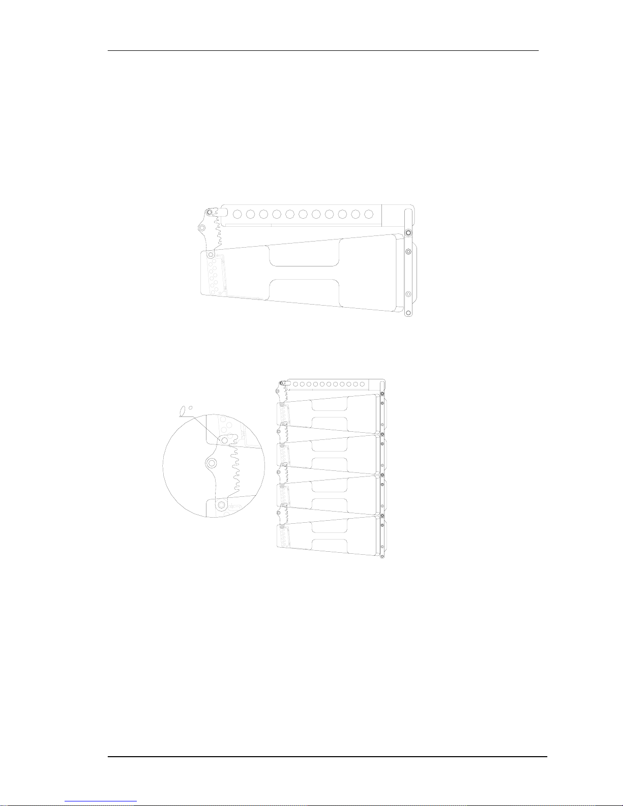
Use the back guide to choose the desired tilt angle (0º, 1º, 2º, 3º, 4º, 5º, 6º, 7º, 8º).
Set the back guide between the back structures of the cabinet that are placed above.
Lock the guides with the safety pins.
When you are flying the first cabinet, follow the previous explanation but set the back
guide between the back structures of the Bumper.
Fig.22. MA-206 Flying with Bumper
Fig.23. MA-206 Flying. Flat Line Array
0 º (Back Guide =0º)
Page 20

Amate Electroacústica,s.l.
MA206/MAW115.Version 1.3 Nov 08
20
Fig.24. MA-206 Flying. Curved Line Array.
8º (Back Guide =8º)
7- OVERVOLTAGE PROTECTION
The MA206D, MAW115D and MAW215D/2K models include over voltage protection.
An electronic circuit compares the input voltage with a reference value on the AC
Input connector (MAINS). When the input voltage is higher than 250 Volts the circuit
starts to work, blocking the input voltage until its value returns to its correct limits
(230V +/- 10% ).
When the Overvoltage LED lights (in RED) (Fig.9. LED OVERVOLTAGE (G), Fig.12.
LED OVERVOLTAGE (G), Fig.14. LED OVERVOLTAGE (G)), the cabinet stops
working (or works intermittently) until the correct voltage values are reached again.
Page 21

Amate Electroacústica,s.l.
MA206/MAW115.Version 1.3 Nov 08
21
8.TECHNICAL SHEETS
MA-206
Line Input (Balanced) Impedance
1.8 V 10k ohms
Mains
230V +/- 10%. Overvoltage protection.
Consumption at Maximum Power
6 A
Frequency Response
LF Usable bandwidth 105Hz - 1k9Hz (-10 dB) (1W, processed)
HF Usable bandwidth 1k9Hz - 18kHz (-10 dB) (1W, processed)
Total Usable bandwidth 105Hz - 18kHz (-10 dB) (1W, processed)
Sensitivity MA206P
LF (4V rms @ 1m) 99 dB SPL
HF (4V rms @ 1m) 105 dB SPL
Total SPL (4V rms @ 1m) 99 dB SPL
Amplifier Power MA206D
LF 1000 W
HF 500 W
Nominal Directivity (-6dB)
Horizontal symmetrical 90º
Vertical defined by the array
System Output Continuous SPL
(Long Term) (flat array)
One enclosure 123 dB
Two enclosures 129 dB
Four enclosures 135 dB
Components
LF 2x6.5" Neodymium Woofer (1.5" voice coil)
HF 1x1" Neodymium Pure Titanium compression Driver (1" ¾ voice coil) mounted on
property waveguide
Enclosure
Width 516.5 mm
Height 198 mm
Depth 493.5mm
Trap angle 2 x 5º
Weight (net) 17 Kg (MA206D) /13Kg (MA206P)
Connectors
MA206D 2x AC PowerCon (Input, Link)
2x XLR (Input, Link)
2x RJ45 for External PC Control
MA206P 1x SPEAKON +1,-1 LOW / +2,-2 HIGH
Material Birch plywood, Stainless Steel Flying Hardware, Black painted Steel Grille
Finish Black (Acrylic resin, ecological water-based)
Rigging Integrated flying hardware and handles
Page 22

Amate Electroacústica,s.l.
MA206/MAW115.Version 1.3 Nov 08
22
MAW-115/D
Line Input (Balanced) Impedance
1.8 V 10k ohms
Mains
230V +/- 10% Overvoltage protection
Consumption at Maximum Power
5 A
Frequency Response
LF Usable bandwidth 38 Hz - 150 Hz (-10 dB) (1W, processed)
Sensitivity
LF (1W rms @ 1m) 97 dB SPL
Amplifier Power
LF 1000 W
Nominal Directivity (-6dB)
Horizontal omnidirectional
Vertical omnidirectional
System Output Continuous SPL
(Long Term) (flat array)
One enclosure 127 dB
Two enclosure 133 dB
Four enclosure 139 dB
Components
LF 1x15" Long excursion Neodymium Woofer (100mm Voice Coil)
Enclosure
Width 516.5mm
Height 498 mm
Depth 493.5 mm
Weight (net) 30 Kg
Connectors 1x AC INPUT PowerCon
1x AC STACKINGOUTPUT PowerCon
1x INPUT XLR Balanced
1x LINK XLR Balanced
2x RJ45 for External PC Control
Material Birch plywood, Stainless Steel Flying Hardware, Black Painted Steel
grille
Finish Black (Acrylic resin, ecological water-based)
Rigging Integrated flying hardware and handles
Page 23

Amate Electroacústica,s.l.
MA206/MAW115.Version 1.3 Nov 08
23
MAW-215/D/2K
Line Input (Balanced) Impedance
1.8 V 10k ohms
Mains
230V +/- 10% Overvoltage Protection
Consumption at Maximum Power
9 A
Frequency Response
LF Usable bandwidth 32 Hz - 140 Hz (-10 dB) (1W, processed)
Sensitivity
LF (2V rms @ 1m) 102 dB SPL
Amplifier Power
LF 2000 W
Nominal Directivity (-6dB)
Horizontal omnidirectional
Vertical omnidirectional
System Output Continuous SPL
(Long Term) (flat array)
One enclosure @ 2000 W 135 dB
Two enclosures @ 2000 W 141 dB
Four enclosures @ 2000 W 147 dB
Components
LF 2x15" Long excursion Neodymium Woofer (100mm Voice Coil)
Enclosure
Width 740 mm
Height 510 mm
Depth 920 mm
Weight (net) 72 Kg
Connectors 1x AC INPUT PowerCon
1x AC STACKINGOUTPUT PowerCon
1x INPUT XLR Balanced
1x LINK XLR Balanced
2x RJ45 for External PC Control
Material Birch plywood, Stainless Steel Flying Hardware, 2mm Black Painted
steel grille
Finish Black (Acrylic resin, ecological water-based)
Rigging Integrated flying hardware and handles
Page 24
Amate Electroacústica,s.l.
MA206/MAW115.Version 1.3 Nov 08
24
9.TROUBLESHOOTING
No Power
• Make sure that the cabinet is plugged in.
• The Fuse is blown. Replace the fuse on fuse holder with one of the same type. This
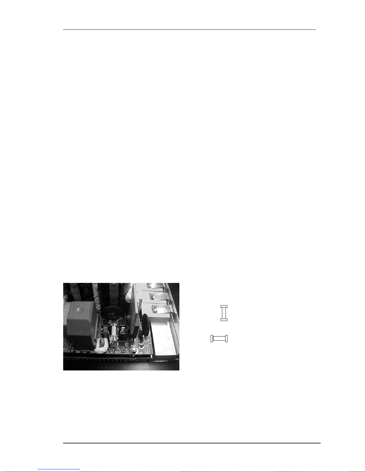
replacement must be done by specialized people as the fuse is set inside the amplification
modules. AC Voltage may be controlled by rotating the Fuse 90º (230V or 115V). See fuse
holder for more information.
No Sound
• Check that the mixer, sound source and processor is sending signal to the unit.
• Check that the cable from the mixer, sound source or processor to the units is correctly
connected. Replace the cable if defective.
• Make sure the output volume (gain) control on the mixing console and processor is
sufficiently turned up to drive the inputs of the speakers.
• Make sure the mixer and the processor do not have a Mute on.
Distorted sound
• The system is overloaded and has reached maximum power. Turn down the mixer's output
or the channel's gain.
Poor bass performance
• Check the polarity of the connections between the mixer/processor and the MA-206
amplifiers. If you have inverted any of the Pins (1,2 or 3) in one of the extremes of the wire,
the losses may be extremely high.
Noise and Hum
• Make sure all connections to the active units are in good conditions.
• Avoid routing the signal cables near AC cables, power transformers, or EMI-inducing
devices.
• Check if there is any light dimmer on the same AC circuit as the cabinet. Connect the sound
system to a different phase than the lights.
VERTICAL: 220V
HORIZONTAL: 115V
Fig.25. Fuse position (front view)
Overvoltage LED (on RED)
• Check that the input voltage is within the right values (230V +/- 10%)
Page 25
Amate Electroacústica,s.l.
MA206/MAW115.Version 1.3 Nov 08
25
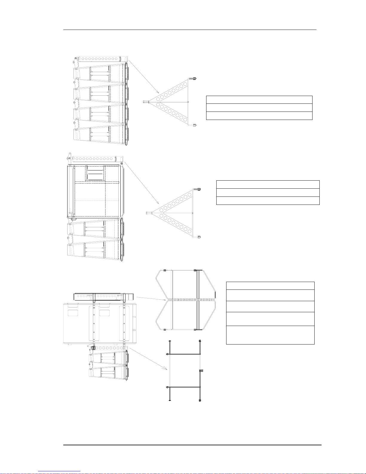
10. MA206 FLYING
TA-206
TA-206
TA-210HD
FA-10/6
MA206
You need
TA-206 Bumper
MA206 + MAW115
You need
TA-206 Bumper
MA206 + MAW215
You need
TA-210HD Bumper
FA-10/6 Frame Adaptor
4 x BL-8 Ball Lock Pins
Page 26
Amate Electroacústica,s.l.
MA206/MAW115.Version 1.3 Nov 08
26
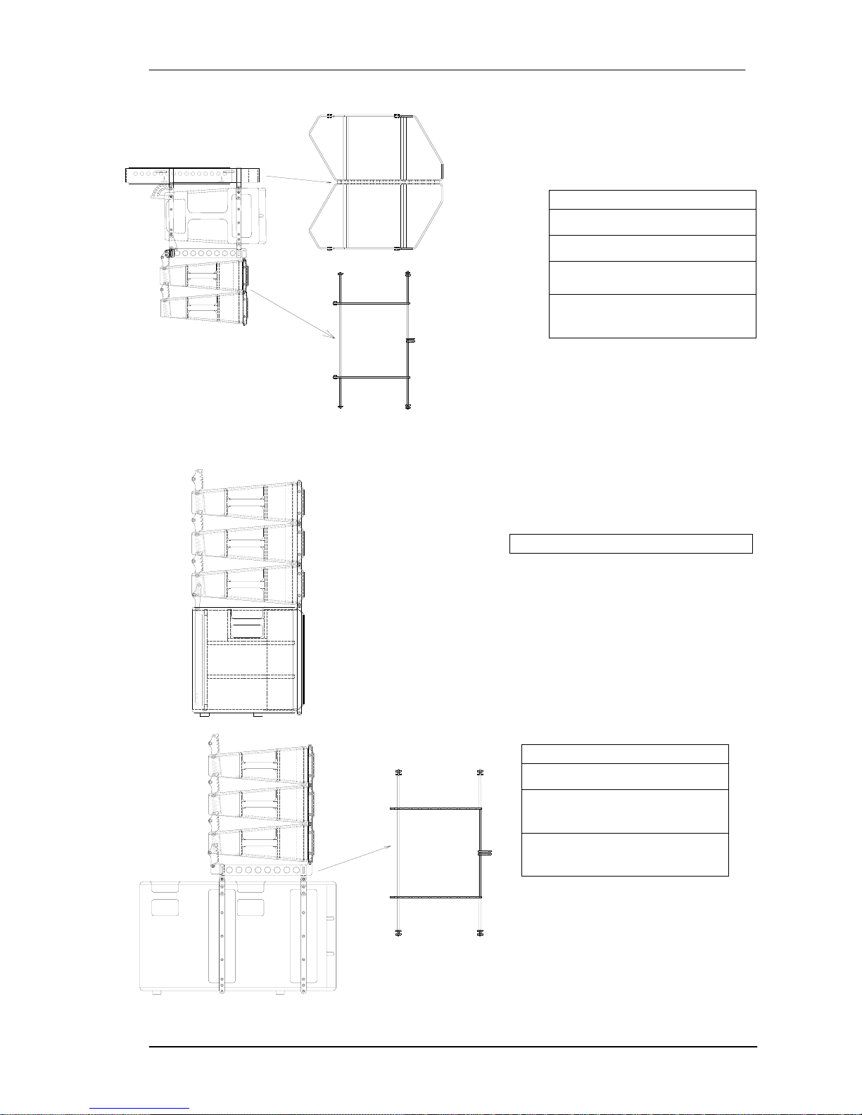
TA-210HD
FA-10/6
11. MA206 STACKING
FA-15/10
MA206 + MA210
You need
TA-210HD Bumper
FA-10/6 Frame Adaptor
4 x BL-8 Ball Lock Pins
MA206 + MAW115
MA206 + MAW215
You need
FA-15/6 Frame Adaptor
4 x BL-8 Ball Lock Pins for
sub
 Loading...