

Page 1

LNC SERIES
LNC-12W
LNC-15W
Pol.Ind.Norte-Perpinyà,25
08226 TERRASSA (Barcelona-SPAIN)
Feb 10
Manual usuario / User’s manual
Page 2
Master Audio
LNC Series. Version 1.0 Feb 10
2
ESPAÑOL
1. INTRODUCCIÓN
1.1. Generalidades
Amate Electroacústica, s.l.
le agradece la confianza depositada en nuestros
productos de la
Serie LNC
Le sugerimos lea atentamente las indicaciones que a continuación exponemos,
confiando en que le serán de gran utilidad para obtener sus mejores resultados.
1.2. Características y presentación
LNC-12W
- Refuerzo de bajas frecuencias
- Altavoz de
12" de Neodimio
- Capacidad de Potencia de 300 W r.m.s
- Sensibilidad de 94 dB (1W/1m)
- Fácil utilización en pasivo-paralelo / bi-amplificado con recintos de la serie B, EL ó
LN.
LNC-15W
- Refuerzo de bajas frecuencias
- Altavoz de 15" de Neodimio
- Capacidad de Potencia de 400 W r.m.s
- Sensibilidad de 98 dB (1W/1m)
- Fácil utilización en pasivo-paralelo / bi-amplificado con recintos de la serie B, EL ó
LN.
2. CONEXIONES
2.1. Descripción conexionado
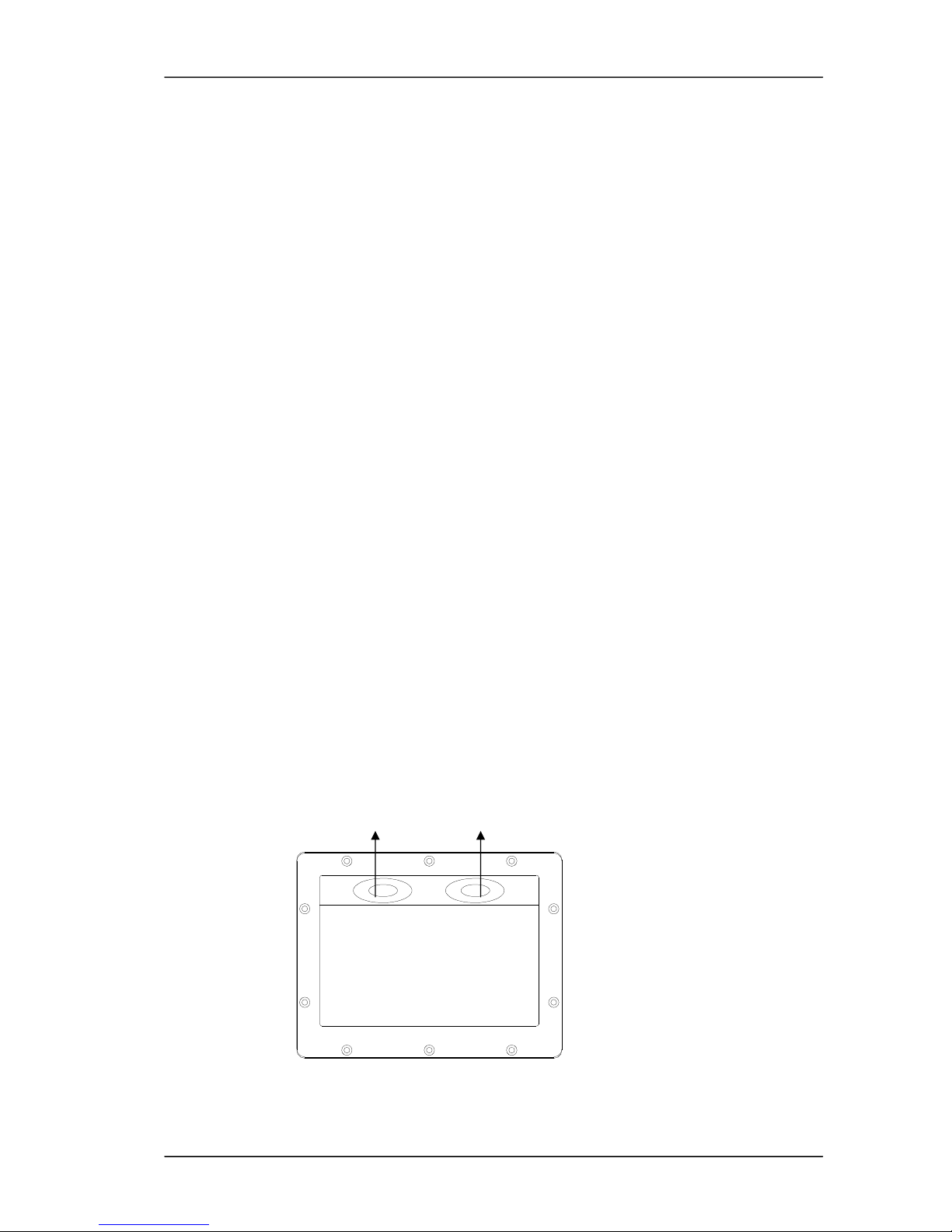
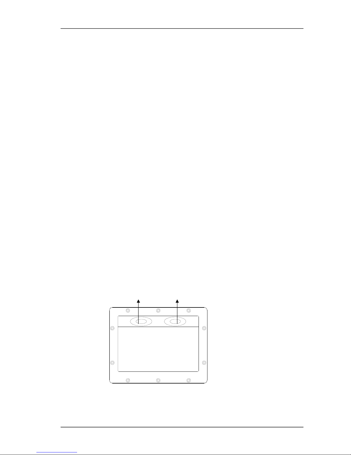
1 1
Fig.1. Conexiones para LNC-12W / LNC-15W
Page 3
Master Audio
LNC Series. Version 1.0 Feb 10
3
1 - SPEAKON : Todos los modelos incorporan dos terminales Speakon y están
preparados para su perfecta conexión en un sistema en paralelo.
ATENCIÓN: Utilice en lo posible cable-manguera de dos conductores, sin apantallar,
bicolor y de buena calidad. Se recomienda el uso de una sección de 4mm2 como
mínimo para cada conductor.
Evítese largas distancias de cableado ya que provocan importantes pérdidas de
potencia y calidad.
2.2. Configuraciones
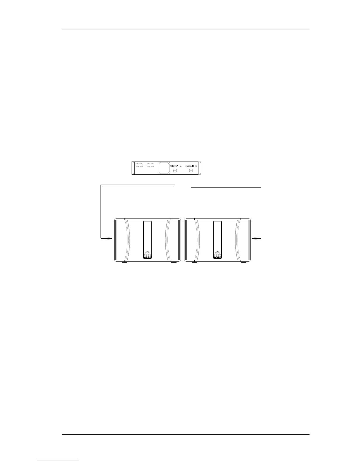
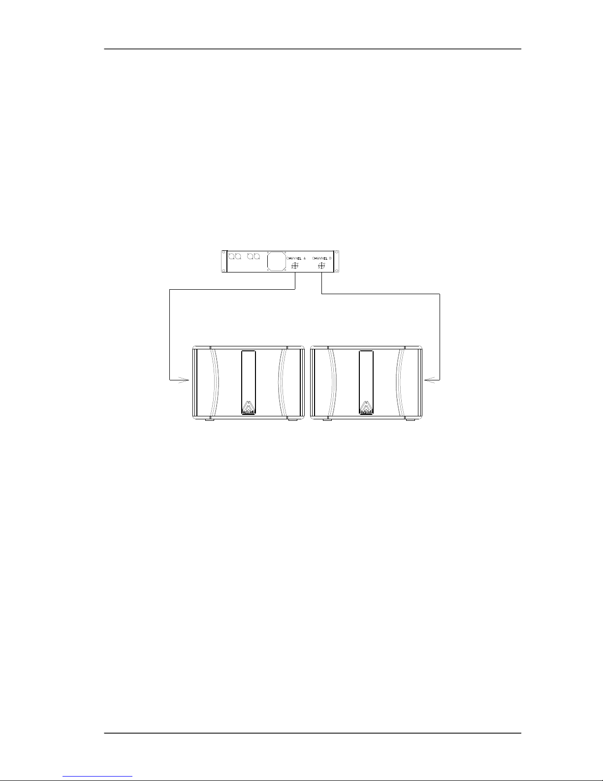
2.2.1. Configuración Estéreo
Conectar cada salida del amplificador LEFT/RIGHT a cada unidad, mediante dos
mangueras, independientemente.
Fig.2. Configuración Estéreo
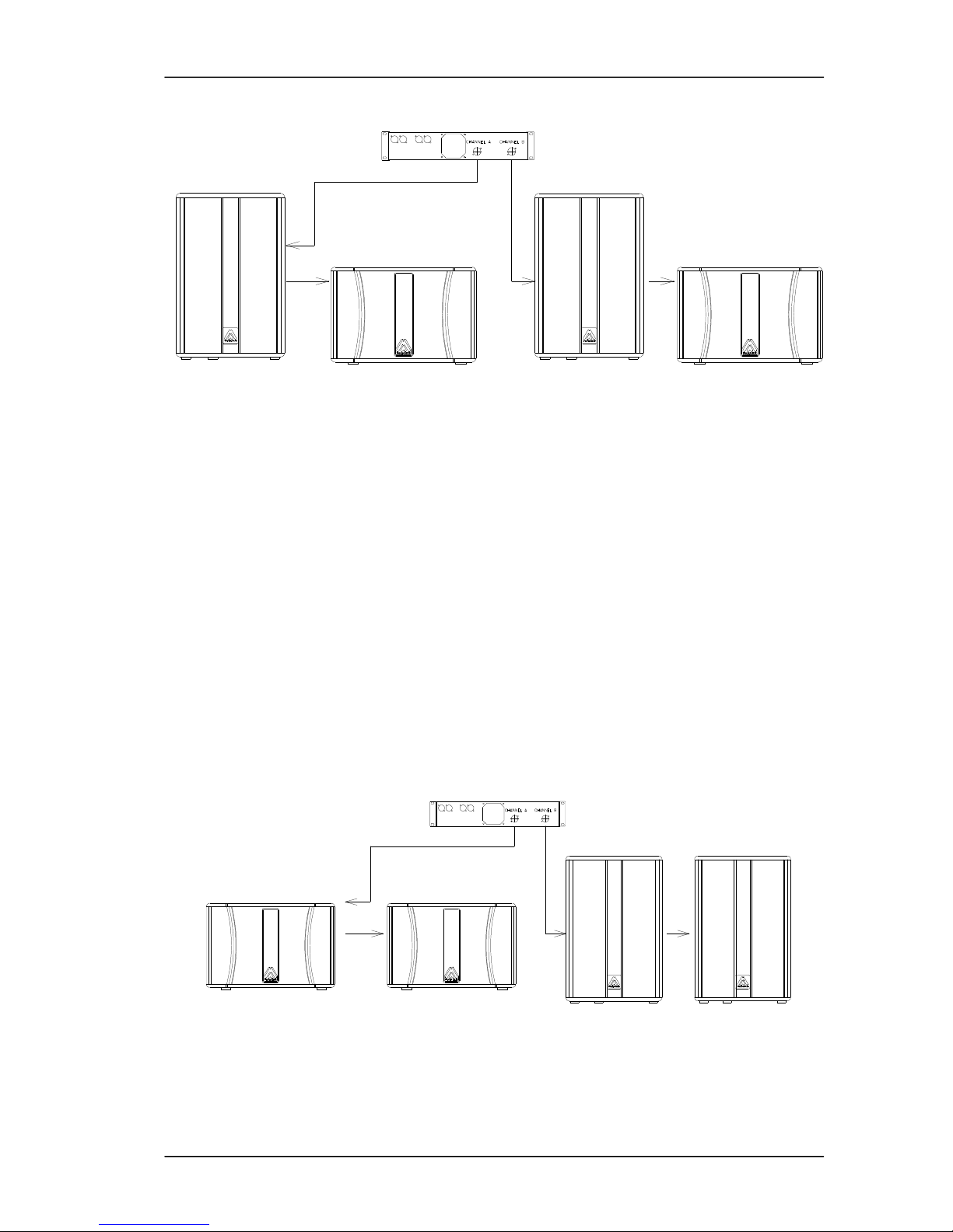
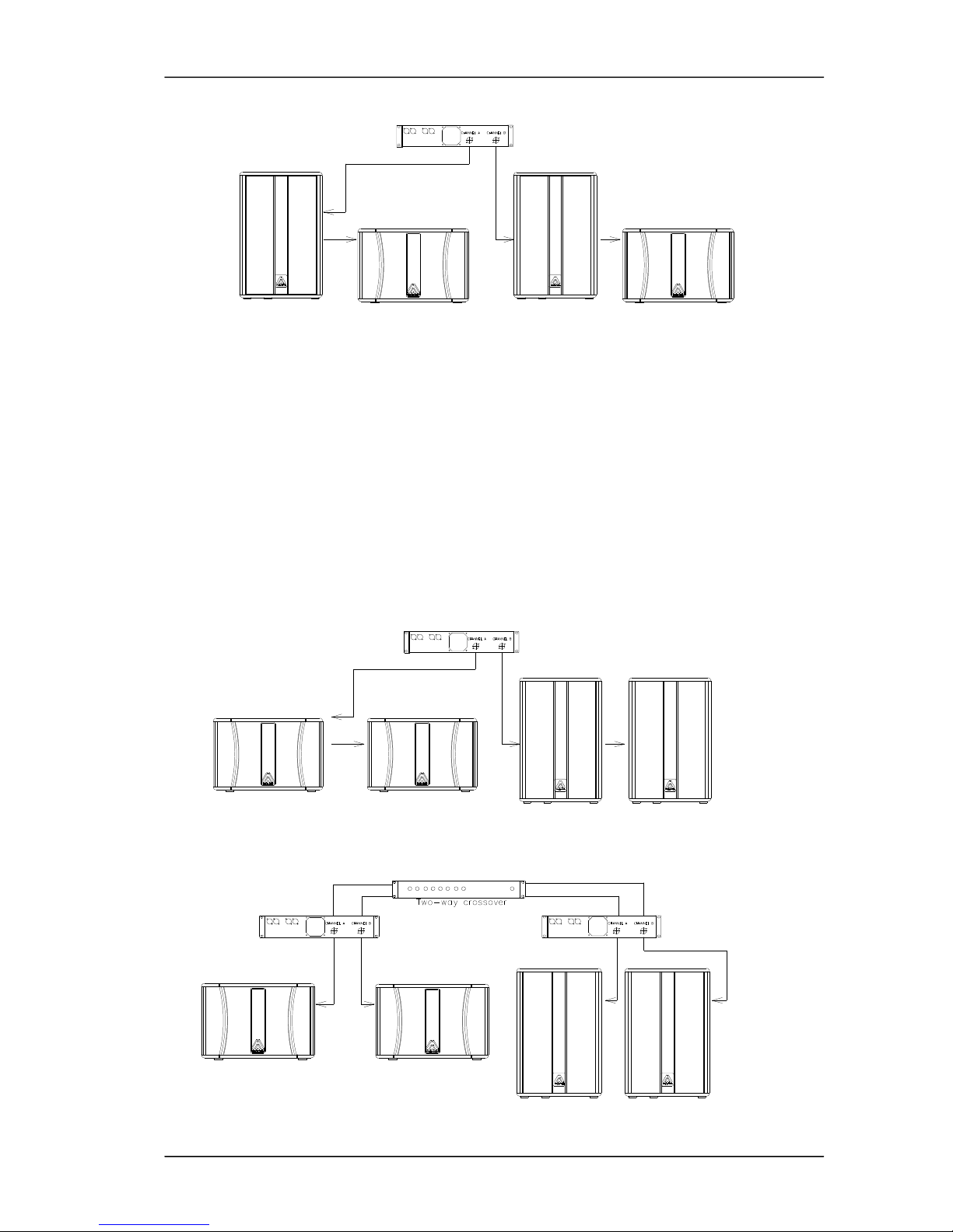
2.2.2. Configuración en Pasivo con sistemas Full Range
Muchas veces le interesará reforzar sus sistemas B/EL/LN Full Range mediante
unidades subwoofer de la serie LNC, tanto en activo como en pasivo.
En el caso pasivo, se dispondrá de un sólo amplificador para todo el sistema.
De una de las salidas del amplificador conectar, mediante cable manguera, la unidad
de graves.
Posteriormente, efectuar un puente desde el conector Speakon esclavo del
subwoofer a su respectiva unidad satélite de medios-agudos, respetando siempre la
correcta polaridad entre ambos sistemas. Proceder de igual manera para el otro
canal.
También es correcto, si la instalación lo requiere, efectuar la conexión a la inversa,
es decir, del amplificador al satélite y luego al subwoofer.
Page 4
Master Audio
LNC Series. Version 1.0 Feb 10
4
Fig.3. Configuración en pasivo con unidades full range
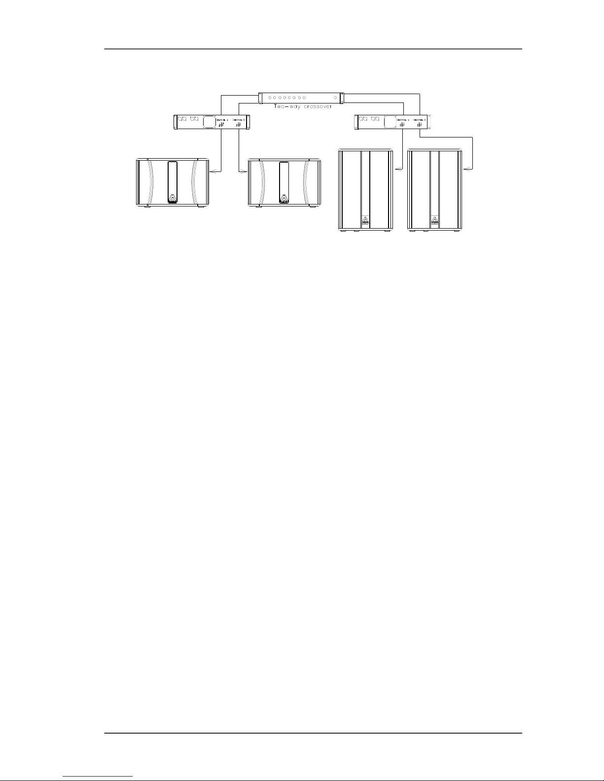
2.2.3. Configuración Bi-Amplificada con sistemas Full Range
Del canal de salida de la etapa de potencia destinada a graves saldremos con una
manguera de la mayor sección posible (4mm2 mínimo) hacia uno de los subwoofers.
Si se dispone de pareja de subwoofers, realizaremos una conexión en puente entre
ambos, respetando siempre la polaridad.
Conectar la otra salida del amplificador independientemente a la caja de mediosagudos.
También es posible destinar un sólo amplificador para los refuerzos de graves,
conectando cada uno de los subwoofers a las dos salidas de la etapa y en
consecuencia, alimentar el sistema de medios-agudos mediante un segundo
amplificador.
Fig.4. Configuración bi-amplificada con unidades full range (opción 1)
Page 5
Master Audio
LNC Series. Version 1.0 Feb 10
5
Fig.5. Configuración bi-amplificada con unidades full range (opción 2)
¡ATENCIÓN!!!!: Para efectuar un puente entre cajas, cada una de ellas dispone de
dos conectores idénticos Speakon que hacen la función de Entrada / Salida
indistintamente. Siempre deben utilizarse los terminales Pin +1/-1, despreciando los
terminales +2/-2 que no están conectados internamente.
3. MONTAJE E INSTALACIÓN
Para la adecuada instalación de los sistemas de cajas acústicas se recomienda lea
atentamente los siguientes consejos.
3.1. Posicionamiento
Para posicionar las unidades de graves, es recomendable que éstas sean colocadas
en el mismo suelo, ya que así se aprovecha, de forma natural, el llamado "efectosuelo" incrementando notoriamente la respuesta en bajas frecuencias.
Le aconsejamos coloque, siempre que sea posible, las unidades de graves bajo el
mismo eje acústico de dónde estén ubicados los satélites.
Si esto no es posible deberían situarse en un punto intermedio entre los canales
Izquierdo y Derecho.
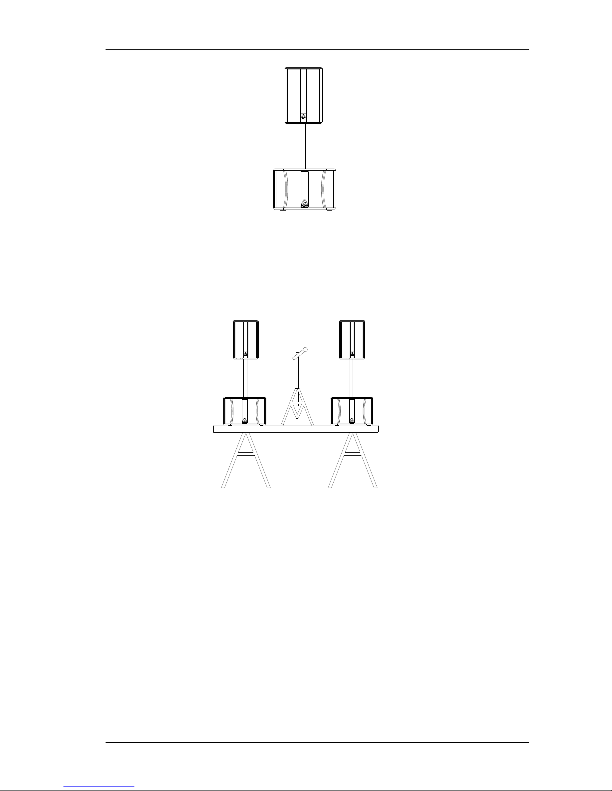
3.2. Utilización con sistemas full range
Los modelos LNC-12W y LNC-15W incorporan integrado en su parte superior una
pletina para cilindro de 35mm (diámetro de una barra estándar). Así podemos
colocar de forma elevada sistemas acústicos que vayan provistos del vaso inferior
para trípode. Evite colocar sistemas montados de esta forma en superficies
inclinadas o irregulares.
Page 6
Master Audio
LNC Series. Version 1.0 Feb 10
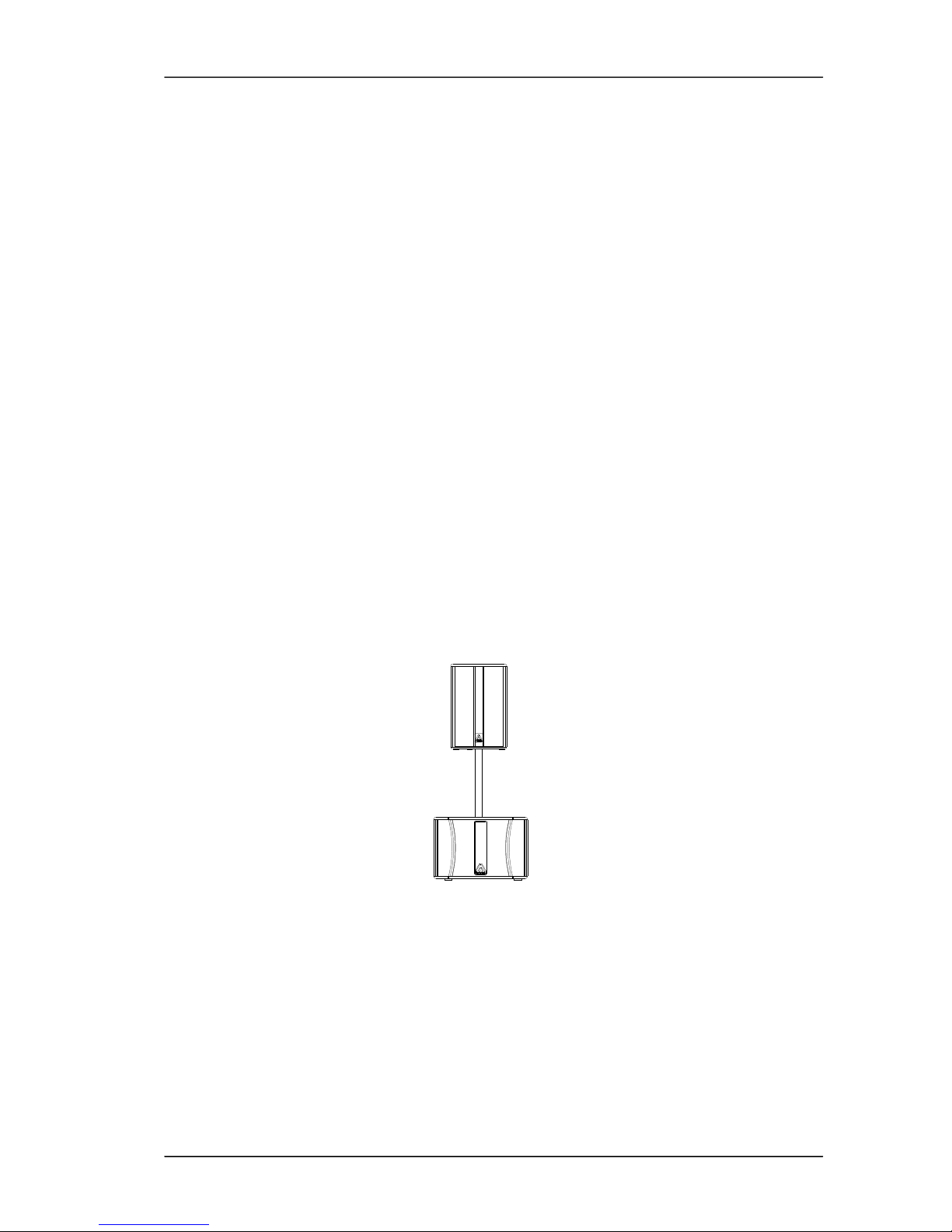
6
Fig.6. Posicionamiento con sistemas full range y barra
3.3. Uso en aplicaciones de Directo (móvil)
Para una aplicación móvil, para Directo o Discoteca, la ubicación clásica sería la de
situar las unidades de graves (una ó dos por canal) a cada lado del escenario (sobre
éste).
Fig.7. Aplicaciones de directo
Para conseguir una reproducción libre de obstáculos, se recomienda coloque las
unidades de Medios-Agudos por encima de las unidades de graves a unos dos
metros de altura.
Si no se dispone de esta altura es conveniente utilizar el clásico trípode para cada
caja y dejar las cajas de graves en el suelo.
¡ATENCIÓN!!! En recintos con problemas de acústica y en los que es necesario
reforzar la respuesta en bajas frecuencias es recomendable agrupar todos los
subwoofers en un mismo punto. De esta manera evitaremos cancelaciones y
obtendremos un nivel de presión acústica mucho más elevado.
3.4. Volado
Los subwoofers de la serie LNC no están preparados para ser volados.
Page 7

Master Audio
LNC Series. Version 1.0 Feb 10
7
4. ESPECIFICACIONES
4.1. Especificaciones LNC-12W
Impedancia
4
Sensibilidad 1W/1m 94dB
Respuesta en frecuencia (-10 dB) 42Hz-170Hz
Capacidad de potencia
R.M.S 300W
Programa 600W
Directividad nominal (-6dB) omnidireccional
Componentes 1x12" woofer neodimio
Recinto
Altura 367mm
Anchura 550 mm
Profundidad 450 mm
Peso (neto) 16 Kg
Conectores 2 x Speakon (IN/LINK)
Material Tablero abedul
Acabado Pintura negra de resinas acrílicas, ecológica a base de agua
4.2. Especificaciones LNC-15W
Impedancia
4
Sensibilidad 1W/1m 98dB
Respuesta en frecuencia (-10 dB) 36Hz-160Hz
Capacidad de potencia
R.M.S 400W
Programa 800W
Directividad nominal (-6dB) omnidireccional
Componentes 1x15" woofer neodimio
Recinto
Altura 450 mm
Anchura 660 mm
Profundidad 490 mm
Peso (neto) 24 Kg
Conectores 2 x Speakon (IN/LINK)
Material Tablero abedul
Acabado Pintura negra de resinas acrílicas, ecológica a base de agua
Page 8

Master Audio
LNC Series. Version 1.0 Feb 10
8
5. APÉNDICE.PÉRDIDA DE POTENCIA (EN %) Y FACTOR DE DAMPING, RELATIVA A
LA LONGITUD DEL CABLE Y SU SECCIÓN
(*) Referido a un amplificador con un Factor de Amortiguamiento de 200:1.
Las secciones de cable inferiores a 2.50 mm2 deben desconsiderarse.
Para instalaciones fijas con cargas a 4 Ohms, es preferible disponer de un cable por
Sistema de Altavoces. No es aconsejable "puentear" las cajas entre sí.
Largo
cable
(m)
Sección
(mm2)
Resistencia
(Ohms)
Pérdida de Potencia
8Ohms 4Ohms 2Ohms
Pérdida
Damping(*)
8Ohms 4 Ohms
0.75 0.042 0.53% 1.05% 2.10% 98 49
1.50 0.025 0.31% 0.63% 1.25% 123 62
2.50 0.013 0.16% 0.33% 0.65% 151 75
1
4.00 0.008 0.10% 0.20% 0.40%
167 83
0.75 0.210 2.63% 5.25% 10.5% 32 16
1.50 0.125 1.56% 3.13% 6.25% 48 24
2.50 0.065 0.81% 1.63% 3.25% 76 38
5
4.00 0.040 0.50% 1.00% 2.00%
100 50
0.75 0.420 5.25% 10.50% 21.00% 17 9
1.75 0.250 3.13% 6.25% 12.50% 28 14
2.50 0.130 1.63% 3.25% 6.50% 47 24
10
4.00 0.080 1.00% 2.00% 4.00% 67 33
0.75 0.840 10.50% 21.00% 42.00% 9 5
1.50 0.500 6.25% 12.50% 25.00% 15 7
2.50 0.260 3.25% 6.50% 13.00% 27 13
20
4.00 0.160 2.00% 4.00% 8.00%
40 20
0.75 2.100 26.25% 52.50% --- 4 2
1.50 1.250 15.63% 31.25% 62.50% 6 3
2.50 0.650 8.13% 16.25% 32.50% 12 6
50
4.00 0.400 5.00% 10.00% 20.00% 18 9
Page 9
Master Audio
LNC Series. Version 1.0 Feb 10
9
ENGLISH
1. INTRODUCTION
1.1. General
Amate Electroacústica, s.l.
would like to thank you for your confidence in our LNC
Series
.
We suggest you to carefully read the following instructions in order to obtain the best
results in performance.
1.2. Features and presentation
LNC-12W
- Low frequency reinforcement unit
-
12" Neodymium Woofer
- Power Handling: 300 W r.m.s
- Sensitivity: 94 dB (1W/1m)
- Passive-parallel/bi-amplified use with B/EL/LN Series cabinets
LNC-15W
- Low frequency reinforcement unit
- 15" Neodymium Woofer
- Power Handling : 400 W r.m.s
- Sensitivity: 98 dB (1W/1m)
- Passive-parallel/bi-amplified use with B/EL/LN Series cabinets
2. CONNECTIONS
2.1. Connection description
1 1
Fig.1. LNC-12W / LNC-15W connectors
Page 10
Master Audio
LNC Series. Version 1.0 Feb 10
10
1 - SPEAKON : All models use two Speakon terminals and are duly prepared for a
perfect connection in a parallel system.
WARNING: It is strongly recommended to use a two-conductor high quality wire, nonshielded and two-coloured. We recommend to use a minimum section of 4mm2 for
each conductor.
Avoid long wire distances as they induce to important power and quality losses
2.2. Configurations
2.2.1. Full Range Stereo configuration
Connect each output of the amplifier LEFT/RIGHT to each cabinet using two wires,
independently.
Fig.2. Stereo configuration
2.2.2. Passive configuration with full range cabinets
There will be times when you will be interested in reinforcing your systems with LNC
subwoofers, in passive mode.
In this case one amplifier will be only used for the whole system.
In passive, connect one of the outputs of the amplifier to the subwoofer through a
wire.
Then, make a bridge from the slave Speakon connector of the subwoofer to its
respective mid-high satellite unit, always respecting the correct polarity between both
systems.
Do the same with the other channel.
It is also correct, if the installation requires so, to make the connection in the opposite
way, that is, from the amplifier to the satellite and then to the subwoofer.
Page 11
Master Audio
LNC Series. Version 1.0 Feb 10
11
Fig.3. Passive with full range cabinets configuration
2.2.3. Bi-Amplified configuration with full range cabinets
A wire with the maximum available section (4mm2 minimum) will have to link the low
frequencies output channel of the amplifier to one of the subwoofers.
Two subwoofers can be also connected by bridge one to another, as long as the
polarity is strictly respected.
Connect the other output of the amplifier to the Full Range cabinets.
It is also possible to use only one amplifier for the low reinforcement, connecting each
one of the subwoofers to the two outputs of the amplifier and consequently,
connecting the Full Range cabinets to a second amplifier.
Fig.4. Bi-amplified with full range cabinets configuration (option 1)
Fig.5. Bi-amplified with full range cabinets configuration (option 2)
Page 12
Master Audio
LNC Series. Version 1.0 Feb 10
12
WARNING!!!!: In order to allow a bridge connection between cabinets, each one of
them has been provided with two Speakon connectors that allow the Input / Output
function indistinctly. Terminal Pins +1/-1 must be always used, disregarding the +2/-2
which are not internally connected.
3. MOUNTING AND PLACEMENT
For a proper installation of the acoustic cabinet systems, it is strongly recommended
to carefully read the following advices.
3.1. Placement
It is advisable to locate the low frequency units on the floor as they can take
advantage of the so-called “floor-effect”, thus increasing the response in the low
frequencies.
If possible, place the subwoofers under the same acoustic axis used for the satellites.
If the above option can not be carried out, then they should be placed in an
intermediate point between the left and right channels.
3.2. Full range cabinet + subwoofer use
The LNC-12W and LNC-15W are equipped with a M20 Plate for a 35mm distance
rod. We can use it to place over the subwoofer the models that are equipped with the
tripod socket. Be careful not to use this system on non-flat surfaces as it may become
unstable.
Fig.6. Full range cabinet with subwoofer
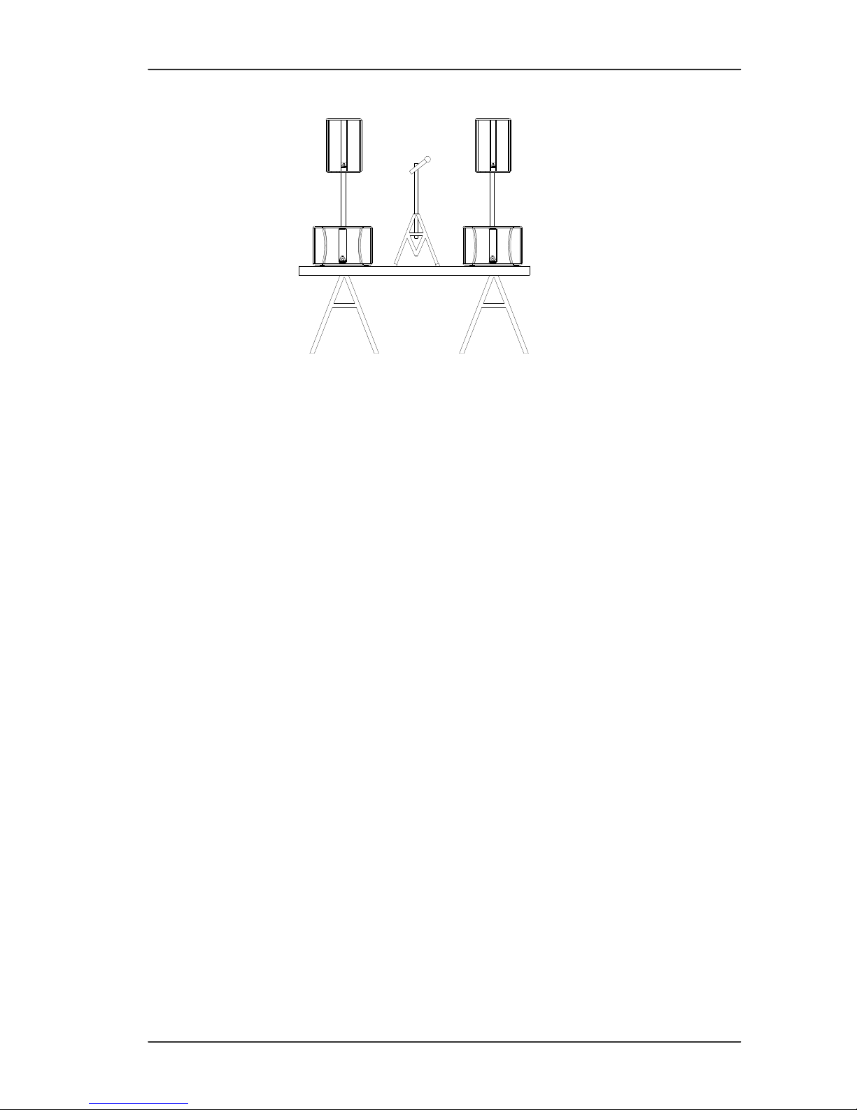
3.3. Live applications (mobile)
For a mobile application, whether it is an outdoor or indoor installation, the common
location is to place the bass units (one or two per channel) on each side of the stage.
Page 13
Master Audio
LNC Series. Version 1.0 Feb 10
13
Fig.7. Mobile applications
To obtain a clear and free-distortion reproduction, it is advisable to place the mid-high
units on top of the low units keeping between them an approximate height of two
meters. If such height cannot be achieved nor maintained, it is advisable to use the
classical tripod for each mid-high cabinet and leave the low units on the floor.
WARNING!!! For installations that suffer from acoustic problems and in which it is
necessary to reinforce the response in the low frequencies, it is advisable to group all
the subwoofers together in the same point. By this way, cancellations will be avoided
and a higher acoustic pressure level will be obtained.
3.4. Flying
LNC-12W and LNC-15W are not prepared for flying.
Page 14

Master Audio
LNC Series. Version 1.0 Feb 10
14
4. TECHNICAL FEATURES
4.1. LNC-12W technical features
Impedance 4
Sensitivity 1W/1m 94dB
Frequency response (-10 dB) 42Hz-170Hz
Power handling
R.M.S 300W
Program 600W
Nominal directivity (-6dB) omnidirectional
Components 1x12" neodymium woofer
Enclosure
Height 367mm
Width 550 mm
Depth 450mm
Net weight 16 Kg
Connections 2 x Speakon (IN/LINK)
Material Birch plywood
Finish Black painted
4.2. LNC-15W technical features
Impedance 4
Sensitivity 1W/1m 98dB
Frequency response (-10 dB) 36Hz-160Hz
Power handling
R.M.S 400W
Program 800W
Nominal directivity (-6dB) omnidirectional
Components 1x15" neodymium woofer
Enclosure
Height 450mm
Width 660 mm
Depth 490mm
Net weight 24 Kg
Connections 2 x Speakon (IN/LINK)
Material Birch plywood
Finish Black painted
Page 15

Master Audio
LNC Series. Version 1.0 Feb 10
15
5. APPENDIX
POWER LOSSES(%) AND DAMPING FACTOR, RELATED TO WIRE LENGTH
AND SECTION
(*) Referred to an amplifier with a Damping Factor of 200:1. Wire sections under
2.50 mm2 are completely inadvisable.
For fixed installations with 4 Ohms load, it is better to have one wire for each speaker
system. It is not advisable to bridge one cabinet to another.
Wire
length
(m)
Section
(mm2)
Resistance
(Ohms)
Power losses
8Ohms 4Ohms 2Ohms
Damping losses(*)
8 Ohms 4 Ohms
0.75 0.042 0.53% 1.05% 2.10% 98 49
1.50 0.025 0.31% 0.63% 1.25% 123 62
2.50 0.013 0.16% 0.33% 0.65% 151 75
1
4.00 0.008 0.10% 0.20% 0.40% 167 83
0.75 0.210 2.63% 5.25% 10.5% 32 16
1.50 0.125 1.56% 3.13% 6.25% 48 24
2.50 0.065 0.81% 1.63% 3.25% 76 38
5
4.00 0.040 0.50% 1.00% 2.00% 100 50
0.75 0.420 5.25% 10.50% 21.00% 17 9
1.75 0.250 3.13% 6.25% 12.50% 28 14
2.50 0.130 1.63% 3.25% 6.50% 47 24
10
4.00 0.080 1.00% 2.00% 4.00% 67 33
0.75 0.840 10.50% 21.00% 42.00% 9 5
1.50 0.500 6.25% 12.50% 25.00% 15 7
2.50 0.260 3.25% 6.50% 13.00% 27 13
20
4.00 0.160 2.00% 4.00% 8.00% 40 20
0.75 2.100 26.25% 52.50% --- 4 2
1.50 1.250 15.63% 31.25% 62.50% 6 3
2.50 0.650 8.13% 16.25% 32.50% 12 6
50
4.00 0.400 5.00% 10.00% 20.00% 18 9
 Loading...