

Page 1
IT - Generatore d’aria calda ad infrarossi
GB - Radiant hot air generator
DE - Infrarotheizgerät
ES - Generador de calor por Infrarrojos
FR - Générateur de chaleur à l’infrarouge
NL - Infrarood warmeluchtgenerator
DK - Varmluft generator med infrarøde stråler
PL - Promiennikowa nagrzewnica powietrza
LV - Karstâ gaisa izstarotâjs
EE - Kiirgus-õhusoojendi
CZ - Naftové infračervené topidlo
HU - Légbefúvós hősugárzó
RO - Radiator infrarosu
BG - Инфрачервен въздушен отоплител
Manuel d’instructions - Handleiding voor gebruik en onderhoud - Brug- og vedligeholdelsesmanuale - Instrukcja obsługi - Ekspluatâcijas
Instrukcija - Kasutus- ja hooldusjuhend - Návod k obsluze - Használati utasítás - Instrucţiunile de utilizare - Инструкция за експлоатация
Libretto uso e manutenzione - Operating manual - Bedienungsanleitung - Manual de Uso y Mantenimiento -
4117.107
Edition 07
Rev.4
IT - IMPORTANTE: Leggere e comprendere questo manuale operativo prima di effettuare l’assemblaggio, la messa in funzione o la manutenzione di questo riscaldatore. L’uso errato del riscaldatore può causare lesioni gravi. Conservare questo manuale a titolo di futuro riferimento. GB - IMPORTANT: Be sure to read and understand this operating manual before assembling, the set up
and functioning or the maintenance of this heater. The misuse of this heater can cause serious injuries. Conserve this manual for future reference. DE - WICHTIG: Lesen und verstehen Sie
dieses Handbuch vor der Montage, der Inbetriebnahme oder der Wartung dieses Heizgerätes. Falscher Gebrauch des Heizgerätes kann zu schweren Schäden führen. Bewahren Sie dieses
Handbuch für zukünftiges Nachschlagen auf. ES - IMPORTANTE: Leer atentamente este manual de Uso y Mantenimiento, antes de utilizar por primera vez este equipo, prestando mucha
atención a todas las recomendaciones indicadas. El uso inadecuado del calentador, puede causar daños graves a personas, animales o cosas. Conservar este manual en lugar seguro y
siempre a disposición para futuras consultas. FR - IMPORTANT: lire attentivement et comprendre ce manuel avant d’effecteur l’assemblage, la mise en marche ou l’entretien du réchauffeur.
Le mauvais usage de celui-ci peut provoquer de graves lésions. Conserver ce manuel comme futur objet de référence. NL - BELANGRIJK: Bestudeer deze handleiding alvorens het apparaat
in elkaar te zetten, in gebruik te nemen, of van een onderhoudsbeurt te voorzien. Verkeerd gebruik van de verwarming kan ernstig letsel tot gevolg hebben. Bewaar deze handleiding voor
verdere naslag. DK - VIGTIGT: Denne manuale bør læses og forstås før monteringen, ibrugtagningen eller vedligeholdelsen af dette varmeapparat udføres. Et ukorrekt brug af varmeapparatet kan medføre alvorlige personlige skader. Opbevar denne manuale for yderligere henvisninger. PL - WAŻNE: Przed przystąpieniem do montażu, ustawiania i eksploatacji lub konserwacji
promiennikowej nagrzewnicy powietrza należy przeczytać i zrozumieć informacje zamieszczone w niniejszej instrukcji obsługi. Niewłaściwe użytkowanie nagrzewnicy może skutkować
poważnymi obrażeniami ciała. Instrukcję należy zachować do wykorzystania w przyszłości. LV - SVARÎGI! Uzmanîgi izlasiet visas instrukcijas pirms sâksiet iekârtas ekspluatâciju vai
tehnisko apkopi. Ěeneratora nepareiza lietođana var izraisît nopietnus miesas bojâjumus: tâdus kâ apdegumi ugunsgrçka vai sprâdziena gadîjumâ, elektriskais đoks, nosmakšana no
tvana gâzes. EE - OLULINE TEAVE: enne soojendi paigaldamist, käivitamist või hooldamist lugege kogu käesolev kasutusjuhend hoolikalt läbi. Soojendi ebaõige kasutamine võib tekitada
tõsiseid kehavigastusi. Hoidke kasutusjuhend alles. CZ - DŮLEŽITÉ UPOZORNĚNÍ: než přistoupíte k montáži, nastavení a používání či údržbě naftového infračerveného topidla, pečlivě si
přečtěte informace uvedené v tomto návodu k obsluze. Nesprávné používání topidla může mít za následek vážná zranění. Návod pečlivě uschovejte pro pozdější použití. HU - FONTOS: A
hősugárzó összeszerelése, beállítása, működtetése vagy karbantartása előtt fi gyelmesen olvassa el és értse meg az alábbi használati utasításban leírt információkat. A hősugárzó helytelen
használata komoly testi sérüléseket okozhat. A használati utasítást tartsa meg későbbi használatra is. RO - IMPORTANT: Înainte de a trece la montarea, setarea, punerea în funcţiune sau
orice altă operaţie legată de conservarea încălzitorului, trebuie să citiţi cu atenţie i să înţelegeţi bine prezenta instrucţiune. Utilizarea neadecvată a încălzitorului poate duce la accidente
i răniri. Instrucţiunile trebuie păstrate pentru a fi utilizate în viitor. BG - ВАЖНО: Преди започване на работа на инфрачервения въздушен отоплител или на каквито и да било
действия свързани с поддръжката му, внимателно трябва да се прочете тази инструкция за експлоатация. Неправилната експлоатация на инфрачервения отоплител
може да доведе до сериозни наранявания, в резултат на изгаряне, пожар, експлозия, токов удар или отравяне с въглероден окис.
XL9 E - XL9 S
Page 2
INDEX
PRODUCT PRESENTATION 9
UNPACKING 9
SAFETY INFORMATION 10
PRODUCT IDENTIFICATION 11
COMBUSTIBLE 11
THEORY OF OPERATION 12
OPERATING INSTRUCTION 12
SAFETY DEVICE 12
MOVING AND TRANSPORTATION 12
PREVENTATIVE MAINTENANCE SCHEDULE 13
ACCESSORIES 14
FAULTS AND THEIR LIKELY CAUSES 15
9
GB
PRODUCT PRESENTATION
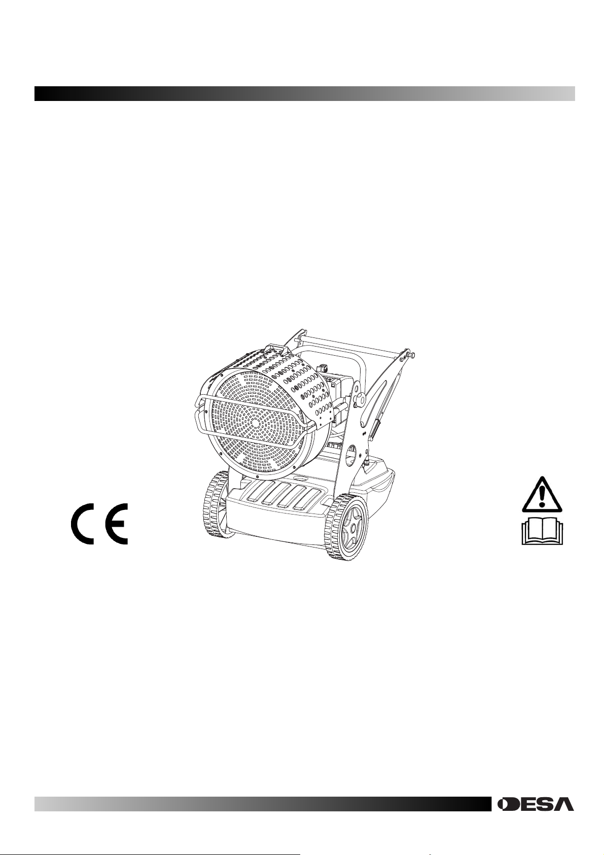
XL9 is a generator of heat by radiation. Radiation technology
is based on the same physical principle behind the warmth of
sunlight. The sun heats bodies without a fl ow of warm air but
by waves of radiation. The radiation method is becoming highly
popular among professional clients because of the countless
advantages it offers. XL9 was designed on the basis of this
physical principle and has become irreplaceable in environments which require a constant, even source of heat for warmth,
defrosting and drying. In addition, its extremely low noise level
makes it suitable for working without having to put up with the
noise that other types of heater normally produce. The generator has rubber wheels for ease of movement and it can also be
raised and set at different heights by means of eyebolts. Its
extended autonomy and automatic thermostat function grant
the operator maximum freedom of use. The external fuel-tank
indicator provides an easy check on whether fuel needs topping
up. The S model has a dual power device that enables a more
effi cient use of the machine under different conditions and dur-
ing the various seasons of the year.
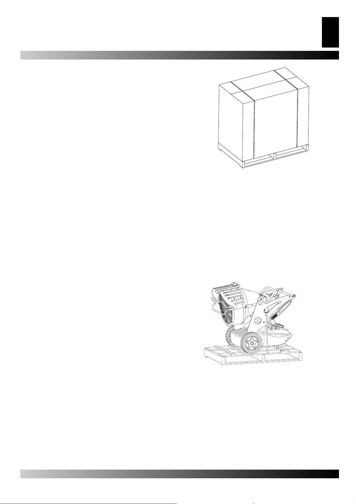
UNPACKING
• Remove the supports used to pack the appliance (Fig. 1).
• Open top side of the box.
• Remove the cardboard from the top.
• Remove the supports that hold the generator to the pallet (Fig.
2).
• Delicately lower the heater off the pallet.
• Dispose of the material used to pack the generator according
to the current government regulations in your area
• Check the machine for eventual damages incurred during
transportation, if the machine appears damaged immediately
inform the store where you purchased it.
Figur 1 - Packaging XL9.
OR SHIPPING AND STORING
If the generator needs to be placed in storage, or if it has
suffered major damage in transport, or needs to be repaired:
• Check for damage, in particular of a nature which could cause
loss of fuel. In this case, empty the tank of the remaining fuel.
• For storage, place the generator on the same pallet from
which it was unpacked and, for return, on any suitable EPAbranded euro-pallet.
• Firmly anchor the generator to the pallet (Fig. 2).
• Whenever possible, slide the cardboard packing from the
top down over the pallet and anchor it fi rmly using suitable
materials (Fig. 1).
• Store the machine in a suitable, dry place and do not stack
more than two. Despatch the generator preferably as shown
Fig. 1 or at least as shown in Fig. 2.
Figur 2 - XL9 on pallett.
Page 3

10
GB
SAFETY INFORMATION
WARNING
IMPORTANT: Read this entire manual carefully before
operating or effectuating any maintenance procedures
on this generator. The misuse of the generator can cause
serious of fatal injuries due to burns, fi res, explosions,
electrical shock or asphyxiation from carbon monoxide.
DANGER: carbon monoxide asphyxiation can be fatal!
Carbon Monoxide Asphyxiation– The fi rst symptoms of car-
bon monoxide asphyxiation are similar to that of the fl u, head-
aches, dizziness and/or nausea. These symptoms could be
caused by the malfunctioning of the generator. In this case go
outside immediately! Have the generator repaired. Then you
may start it again. Some people are more affected by the effects
of carbon monoxide than others, especially pregnant women,
those who suffer from heart or lung disease or anaemic people;
also those who have consumed alcoholic beverages, and those
who are at high altitudes. Be sure to read and understand all of
the warnings. Conserve this manual for future reference: it will
provide you with instructions to operate your generator safely
and correctly. Use only kerosene or diesel to diminish the risk of
fi re or explosion. Never use gasoline, naphtha, paint thinners,
alcohol or other highly fl ammable combustants.
• Filling the Tank.
a) The personnel charged with fi lling the tank should be qualifi ed
and completely familiar with the factory instructions and the
current governmental regulations regarding the secure
provision of generators.
b) Use only the type of fuel expressly specifi ed on the
identifi cation plate located on the generator.
c) Before fi lling the tank, extinguish all of the fl ames, including
the pilot light and wait for the generator to cool down.
d) While fi lling the tank inspect all of the fuel lines and their
junctions to check for fuel losses. Any losses must be
repaired before starting the generator again.
e) Under no circumstances should you conserve a quantity of
combustible superior to that which is necessary to maintain in
function the heater for one day in the same building or nearby
the heater. The fuel storage cisterns should be located in a
separate building.
f) All of the fuel tanks should be located a minimum safety
distance from the heater, (like current government regulation),
as well as oxyhydrogen blowpipe/ torches, welding equipment
and similar ignition sources (with the exception of the fuel tank
incorporated in the generator).
g) The fuel should be stored in areas where the fl ooring will
not soak up any fuel spills or any drips of fuel line, the fl ame
underneath that could cause a fi re.
h) All fuel storage must be effectuated in compliance with the
current government regulations.
• Never use the generator in rooms where gasoline, paint thinner, or other highly fl ammable materials are located.
• While the heater is in use follow all of the local ordinances and
current government regulations
• Heaters used close to large pieces of fabric, curtains or other
similar materials must be situated at a safe distance from
these objects. The minimum safety distance is that which is
advised by the current regulations in the your country. It is
also advisable to use fi reproof materials for coverings. Such
materials should be fastened in a safe manner, so as to avoid
their catching fi re and prevent interference with the generator
caused by wind.
• Use only well ventilated areas. Predispose an opening or
at least an air exchange system that meets the current governmental regulations in your area so that fresh air will be
provided.
• Supply the generator with the proper voltage and frequency as
specifi ed on the identifi cation plate.
• Use only extension cords with three wires correctly connected
to a grounded plug.
• The minimum safety distance is the distance required by the
current governmental regulations in your area.
• Place the generator in a position so that when it is hot or in
function it will be on a stable and level surface, so that you
avoid starting a fi re
• When you move or store the generator, maintain it in a level
position in order to avoid fuel loss.
• Keep children and animals away from the generator.
• Disconnect the generator when it is not in use.
• When it is controlled by another device (like a thermostat or a
timer), the heater could turn itself on at any time.
• Never place the generator in inhabited rooms.
• Never obstruct the aspiration or dissipation vents.
• When the heater is hot, connected to the power supply or in
function it should never be moved, handled, or refi lled and no
maintenance should be performed on it.
• Smoke that is produced from the fi rst combustion is due to the
evaporation of organic materials (ceramic) present in the combustion tank and anticorrosion oil present on the surface of the
burner. After a few minutes the smoke will stop.
• The environmental operating temperature is –30°C + 30°C
Page 4
11
A.
B.
C.
D.
E.
G.
H.
F.
R.
I.
D.
L.
M.
N1.
O1.
Q.
T.
S.
P.
U1.
U2.
U1.
N2.
N2.
O2.
GB
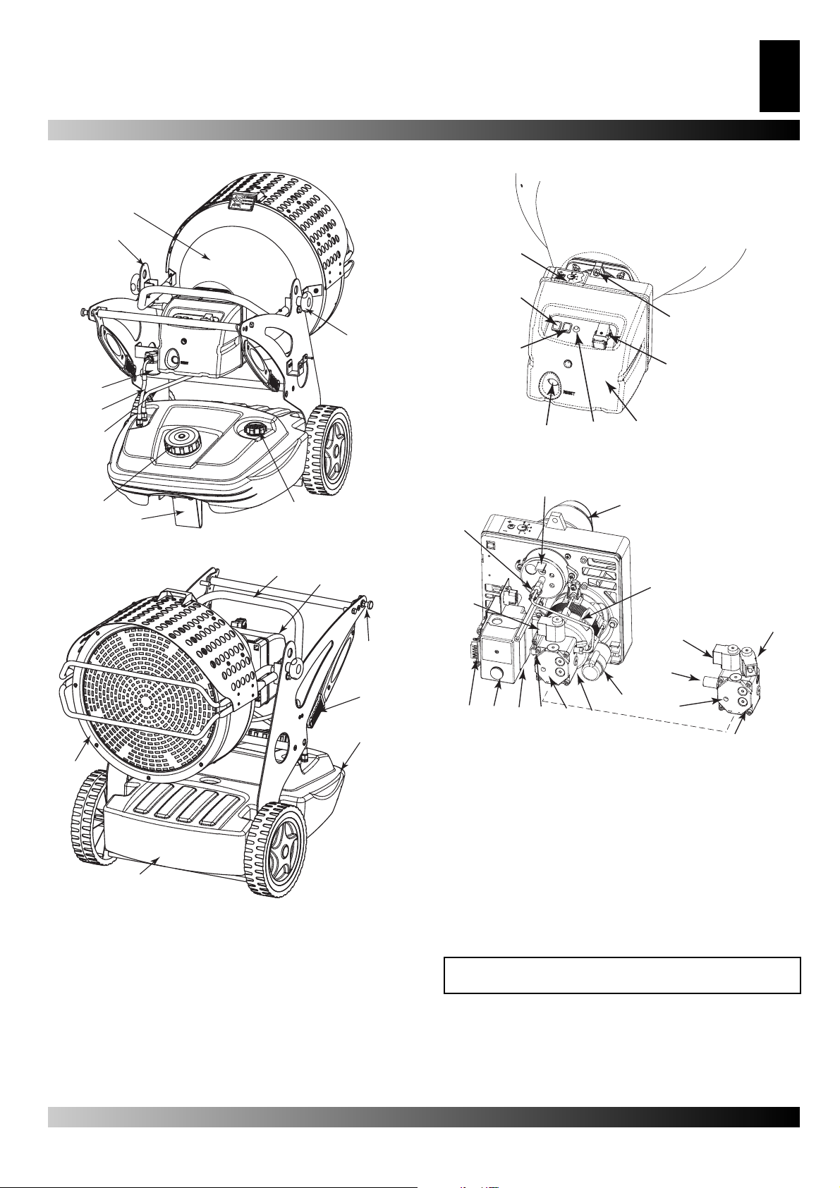
PRODUCT IDENTIFICATION
A.
B.
C.
D.
E.
F.
G.
Figur 3 - Model XL9 back view.
H.
IDENTIFICATION OF THE BURNER PARTS XL9 E - S
I.
Figur 5 - Function controls XL9.
R.
L.
M.
Figur 4 - Model XL9 front view.
A. Combustion chamber, B. Hole for raising generator, C. Fuel
fi lter or pre-heated fi lter (optional), D. Fuel supply, E. Fuel Re-
turn, F. Fuel tank cap, G. Foot or wheel (optional), H. Fuel level
indicator , I. Block of the group combustion, L. Radiant defl ector,
M. Fuel drain plug, N. Fuel tank, O. Handle to move the generator, P. Hinge block, Q. Burner, R. Inclination regulator.
Q.
P.
O.
N.
Figur 6 - Components burner XL9.
A. Air vent regulator, B. Lighted ON/OFF button, C. ON/OFF
switch depending on power option, D. RESET Button, E. Power
indicator, F. Burner coffer, G. Thermostat plug, H. Screw for burner block, I. Post-ventilation device, L. Flame control device, M.
Transformer, N
sure regulator P
fuel pump, P. Condenser, Q. Motor, R. Burner tube, S. Combus-
tion head regulator , T. Photo-resistance, U1. Electrovalve 1°
fl ame step, U2. Electrovalve 1° fl ame step.
1. Pressure regulator P
of the pump, O1. XL9 E fuel pump, O2. XL9 S
2
of the pump, N2. Pres-
1
COMBUSTIBLE
WARNING: The generator runs ONLY on kerosene or diesel fuel.
The use of impure combustible can cause:
• blockage of the combustible fi lter and nozzle;
• formation of carbonaceous deposits on the electrodes;
At low temperatures use non-toxic antifreeze.
Page 5
12
GB
THEORY OF OPERATION
The ventilation needed for proper combustion is produced by a
fan inside the burner. The air exits the burner sleeve and mixes
with the fuel which is nebulised by a high-pressure nozzle. The
fuel is aspirated from the fuel tank by a rotary pump which forces
it at high pressure up to the nozzle for nebulisation.
OPERATING INSTRUCTIONS
WARNING: Before putting the generator in function, and
therefore before connecting it to the electrical system,
you must check to see if the electrical systems technical
characteristics correspond to those on the identifi cation
plate of the generator.
STARTING THE GENERATOR
1. Follow all of the safety information.
2. Fill the tank with diesel fuel or kerosene.
3. Close the fuel cap
4. Plug the alimentation cord into a grounded wall plug with
the same tension as the one written on the generator’s
identifi cation plate.
STARTING WITHOUT A THERMOSTAT
• BURNER XL9 E
Set the switch (B Fig. 5) to the ON position (I). It begins the
period of pre-ventilation and after approximately 10 seconds
ones the combustion has beginning.
• BURNER XL9 S
WARNING: Before starting the generator to make sure
that the button (C Fig. 5) is in position
Set the switch (B Fig. 5) to the ON position (I).It begins the period of pre-ventilation and after approximately 10 second ones
the combustion has beginning.
For having the maximum potentiality portare set the switch (C2
Fig.5) to the
position.
STARTING WITH A THERMOSTAT
Regulate the thermostat or the control device (for example a timer), if connected, so that it will allow the generator to function.
WARNING: The generator can ONLY function
automatically when the control device, for example a
Thermostat or a Timer, is connected to the generator. To
connect the control device to the machine consult the
paragraph entitled “ELECTRIC DIAGRAM”.
.
WARNING: The electric power that feeds the generator
must be grounded and have a differential magneticthermal switch. The generator’s electric cord must be
attached to a plug equipped with a section switch.
TURNING THE GENERATOR OFF
Turn the switch (B Fig. 5) to the OFF position (O) or turn the thermostat or control device (Timer) off if there is one connected.
The fl ame will go out and the ventilation will continue until it has
fi nished its post-ventilation cycle (cooling down).
WARNING: Before unplugging the alimentation cord from
the wall, wait until the post-ventilation cycle is completely
fi nished (it will take approximately 3 minutes to cool
down).
SAFETY DEVICE
The generator is equipped with a safety device (L Fig. 6), which
controls the fl ame. If one or more anomalies occur when the
generator is functioning, the device will block the burner and the
RESET button (D Fig. 5 or 6) will light up.
The generator also has a post-ventilation device which enables
optimal, automatic cooling of the combustion chamber for some
3 minutes.
Before turning the generator on again you must identify and
eliminate the cause that blocked the machine.
MOVING AND TRANSPORTATION
“NOTICE: before raising or moving the machine ensure
that the fuel tank caps (F and H Fig.3 ) are fi rmly closed”.
TRANSPORT
The generator is easy to move and it may be fi xed in a raised
position thanks to its special eye-bolt mechanism (B Fig. 3 or
Fig. 7). This enables it to be set in the most suitable position for
heating, defrosting and drying.
MOVEMENT
Before starting the machine or after the fuel line has been
completely emptied, the fuel fl ow to the nozzle should be
insuffi cient to cause the intervention of the security device which
controls the fl ame (see the “SAFETY DEVICE” paragraph)
that stops the generator. In this case, after having waited
approximately one minute, push the Reset button (D Fig. 5 and
6) and start the machine.
If the machine isn’t working you should fi rst control the
following:
1. Make sure that the fuel tank (N Fig. 4) still contains fuel;
2. Press the Restart button (D Fig. 5 and 6).
If the generator still isn’t functioning consult the “FAULTS AND
THEIR LIKELY CAUSES” paragraph to identify the cause.
WARNING: Before the second ignition (generatore extinguished and adequately cold) to assure the blocking of
the screws that block the anterior defl ector (L Fig. 4).
Figur 7 - Hooks in order to raise.
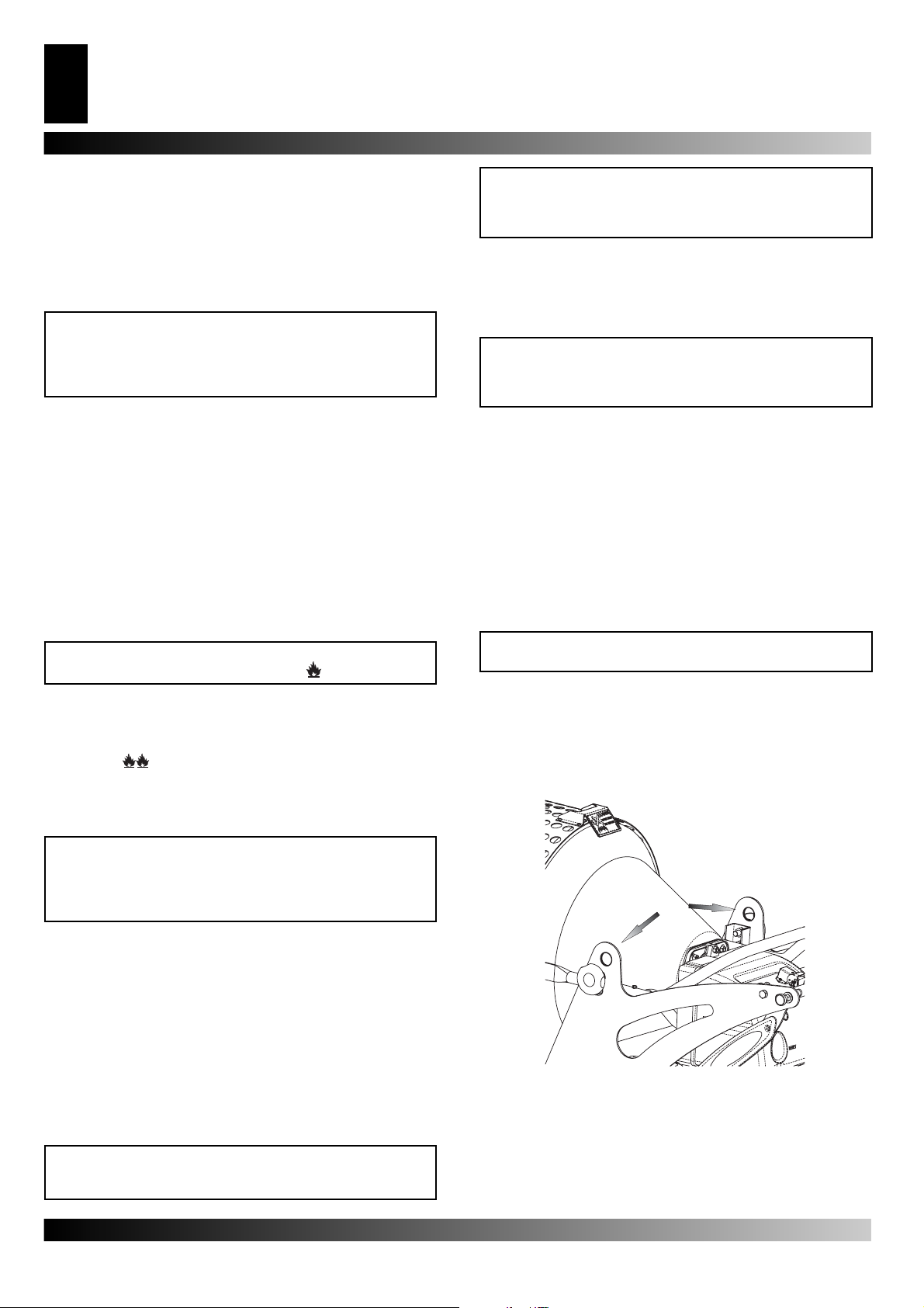
Before picking up or moving the machine you must check to insure that the tank caps (G Fig. 3) are tightly shut. The generator
may be supplied with a rotating wheel. In this case, if the fl oor-
ing allows it you may push the generator like a cart. In the case
the machine does not have rotating wheels it is necessary to
unblock the hinge (P Fig. 4) located on one of the lateral struts of
the generator. Lower the handle from its “resting position” (Fig.
Page 6

13
A.
B.
C.
D.
A.
B.
C.
D.
A.
B.
C.
D.
A.
C.
B.
GB
8) Turn the handle to the “Transportation Position” (Fig. 9). Lift
the generator and position it so that it is resting on the two anterior wheels.
WARNING: Before moving the machine you must: turn
the machine off by following the indications provided in
paragraph “TURNING OFF THE GENERATOR”; unplug
the electrical source by pulling the plug out of the wall
and waiting for the generator to cool down.
Figur 8 - Position close handles XL9.
Figur 9 - Position open handles XL9.
PREVENTATIVE MAINTENANCE
SCHEDULE
WARNING: Before beginning any maintenance operation
you must: turn off the machine following the instructions in
the “TURNING OFF THE GENERATOR” paragraph; unplug
the electrical alimentation by unplugging the cord from the
wall plug and waiting for the generator to cool down.
The instructions in this paragraph regarding the time between
service checks depend a lot on the cleanliness of the fuel and
the type of environment the generator is used in – the times
given are for well-ventilated environments with little dust and
considering the use of clean fuel.
Every 50 hours of operation you must:
• Dismantle the on-line cartridge (see “CLEANING THE FUEL
FILTER”) extract and clean the cartridge;
Every 200 hours of operation you must:
• Dismantle the pump fi lter (see “CLEANING THE PUMP FIL-
TER) extract and clean it;
Every 300 hours of operation you must:
• Dismantle the burner and clean inside the burner’s tube, the
fl ame disk and the electrodes regulating, if necessary the distance (see “CLEANING OF THE BURNER”).
CLEANING THE FUEL FILTER
A. O-rings
B. Plastic cup
C. Filtering
element
D. Body of
IN/OUT of the
fuel
Figur 10 - Filter XL9.
• Unscrew the plastic cup and extract the fi ltering element
(cartridge);
• Clean it well with kerosene;
• Insert the fi lter element back into its place and screw the cup
back into the main body of the combustion fi lter.
CLEANING THE PUMP FILTER
• Dismantle the burner coffer (F. Fig. 5), to identify the pump of
A. Nut for
blocking the
pump fi lter
B. Single
electrovalve
for XL9 E doble electrovalve for XL9 S
C. Filter
D. Pump
Figur 11 - Pomp of burner XL9 E and XL9 S.
the burner (O
• Unscrew the nut (A Fig. 11) that blocking the fi ltering element
to the pump;
• Extract the fi ltering element (C Fig 11) outside its place;
• Clean it well with kerosene;
• Insert the fi ltering element back into its place and screw the
nut to the pump.
1. o O2 Fig. 6);
CLEANING THE BURNER
• Remove the screw (H Fig. 5) that blocks the burner (A Fig. 3)
in the combustion chamber;
• Extract the burner from the combustion chamber (Fig. 3);
• Remove the three screws ( B Fig. 12) that hold the burner tube
(A Fig. 12);
A. Burner
tube
B. Screw of
the burner
tube
C. Screw
Figur 12 - Disassembly shell-burner.
• Dismantle the tube;
Page 7

14
GB
• Remove the screw (C Fig. 12) that holds the group diskfl ame-
electrodes and pull out the nozzle holder (see Fig. 13);
• Clean the fl ame disk (D Fig. 14) and the electrodes (E Fig. 14);
• Unscrew the nozzle (G Fig. 14) from the nozzle holder (F Fig.
14) clean it and if necessary replace it;
• Mount the nozzle (G Fig. 14) in its holder;
C. Screw of
the group
diskfl ame-
electrodes
C.
Figur 13 - Disassembly group diskfl ame-electrodes.
4mm
E.
G.
4mm
22 m m
C. Screw, D. Flame disk, E. Electrodes, F. Tube, G. Nozzle
Figur 14 - Distances electrodes nozzle.
• Remount the group diskfl ame-electrodes placing it at a correct
distance as the illustration (Fig. 14) shows.
D.
6-7mm
F.
C.
CONNECTING THE CONTROL DEVICE
A.
B.
C.
D.
E.
WARNING: Before beginning any maintenance operation
you must: stop the machine according to the instructions
provided in the paragraph “TURNING OFF THE GENERATOR”; disinsert the electrical supply by unplugging it and
waiting for the generator to cool down.
PRE-HEATING FILTER
ROTATING WHEEL WITH BRAKES
ACCESSORIES
THERMOSTAT
Page 8

15
GB
FAULTS AND THEIR LIKELY CAUSES
WARNING: Before beginning any maintenance operation you must: stop the machine according to the instructions provided
in the paragraph “TURNING OFF THE GENERATOR”; disinsert the electrical supply by unplugging it and waiting for the generator to cool down.
Symptoms Possible cause Solution
The machine stops with
fl ame.
RESET button (D Fig. 3 o 5)
on.
The machine stops, spraying fuel without verifying the
fl ame. RESET button (D Fig.
3 o 5) on.
The machine doesn’t spray
fuel and stops.
RESET button (D Fig. 3 o 5)
on
The burner doesn’t start. 1) The control device (Thermostat or Timer) is on.
Flame is not well confi rmed
with an unpleasant odour,
black smoke or fl ames coming
out of the anterior defl ector.
1) Photo-resistance circuit is broken or the Photo-resistance is dirty with smoke residue.
2) Dirty fuel fi lter.
3) Flame Control device Circuit is broken.
4) Flame disk or tube (Fig. 14, 15, 17) dirty.
1) The electrical system is not compatible.
2) Ignition Transformer (M Fig. 4 o N Fig. 6) disconnected or broken.
3) Ignition Transformer wires short circuit to
ground.
4) The electrodes are not at the proper distance.
5) The electrodes short circuit to ground because
they are dirty or the insulation is damaged.
1) Photo-electric cell sees a strong source of light
2) The power supply is missing a phase to the
motor.
3) Fuel is not arriving to the pump.
4) No fuel in the tank.
5) Nozzle clogged.
2) Short circuit in Photo-resistance (T Fig. 4 o P
Fig. 6).
3) Power loss due to: disconnected switch (4) or
disconnected main switch due to power loss in
the line.
4) The installation of the control device (Thermostat or Timer) is not correct.
5) Break inside the fl ame control device.
6) Fuse inside the burner bonnet.
1) Low pulverisation pressure.
2) Insuffi cient combustible air
3 Nozzle clogged because it is dirty or old.
4) Water in the fuel. Poor quality fuel.
5) The tank is running out of fuel.
1) Clean or replace the Photo-resistance.
2) Remove fi lter and clean it.
3) Replace the fl ame control the circuit.
4) Dismantle and clean it.
1) Verify the entire circuit.
2) Replace it.
3) Replace it.
4) Reposition them at the correct distance (see
Fig. 15).
5) Clean them or, if necessary replace them.
1) Place the machine so that the light source
does not directly face the front defl ector.
2) Control the electric system.
3) Control the fuel supply lines (D Fig.2).
4) Resupply the fuel tank.
5) Dismantle and clean or replace it.
1) Raise the value or control the Timer settings.
2) Replace it.
3) Turn off the electric system and then turn off
the switches or wait for the power supply to
return.
4) Control the installation following the description in the “CONNECTRING THE CONTROL
DEVICE” paragraph.
5) Replace it.
6) Open the burner coffer (F Fig. 3 o E Fig. 5)
and replace it.
1) Reestablish the correct value
2) Increase the combustible air.
3) Clean or replace the nozzle.
4) Drain the fuel from the appropriate drain plug
(M Fig. 2).
5) Resupply the tank.
Page 9

101
IT - CERTIFICATO CE DI CONFORMITÀ
GB - CERTIFICATE CE OF CONFORMITY
DE - KONFORMITÄTSBESCHEINIGUNG
ES - CERTIFICADO CE DE CONFORMIDAD
FR - DÉCLARATION DE CONFORMITÉ À LA CE
NL - CE CONFORMITEITSVERKLARING
DK - KONFORMITETS - SERTIFITIKAT
PL - ATEST
LV – PRODUKTA ATBILSTÎBAS SERTIFIKÂTS
EE – VASTAVUSSERTIFIKAAT
RO- DECLARAŢIA DE CONFORMITATE CE
BG - ДЕКЛАРАЦИЯ ЗА СЪОТВЕТСТВИЕ СЕ
La sottostritta ditta: - The underwrite company: Die undterzeichnende Firma: - La Firma que suscribe: La société suivante: - Ondergetekende:Onder-
getekende: -Zemâk parakstîjusies kompânija : Allakirjutanud ettevõte : Subsemnatele : Долуподписаната:
DESA Europe B.V. Postbus 271 - 4700 AG Roosendaal - NL
Declares under its responsability that the machine Ertklärt auf eigene Verantwortung, dass die Maschine: Declara bajo su propia responsabilidad, que la màquina:
Enkarer pri eget ansvar at mzikin Niżej podpisane przedsiębiorstwo świadome swojej odpowiedziałności oznajmie, że maszyna:Ar visu atbildîbu apliecina, ka zemâk norâdîtâ iekârta :
Kinnitab omal vastutusel, et seade:Întreprinderea, contientă de responsabilitatea sa face cunoscut faptul că utilajul: Декларира под отговорност, че машинаta:
Varmluft generator med infrarøde stråler - Promiennikowa nagrzewnica powietrza - Karstâ gaisa izstarotâjs - kiirgus - õhusoojendi -
Atteste sous sa responsabilité que la machine: Verklaart verantwoordelijk te zijn voor onderstaande machine:
Generatore d’aria calda ad irraggiamento - Radiant hot air generator
Heißluftgenerator - Generador de calor por infrarrojos -
Générateur d’air chaud à rayonnement - Infrarood warmeluchtgenerator -
Radiator încălzitor de aer - Инфрачервен въздушен отоплител
Dichiara sotto la propria responsabilità che la macchina:
XL9 E
XL9 S
E’ conforme alle direttive:
The machine complies with:
Entspricht den:
Està realizada conforme a las directivas:
Est conforme aux normes:
Is in overeenstemming met de richtijnen:
Apparatet modsvarer:
Maszyna odpowiada:
Atbilst sekojošiem standartiem:
vastab standarditele:
Utilajul corespunde:
Машината съответства на:
98/37/CE 91/368/CEE 93/44/CEE 93/68/CEE, 89/336/CEE, 92/31/CEE, 93/97 CEE, 73/23/CEE
Roosendaal, 09/14/2005
Augusto Millan (Managing Director)
Page 10

102
4
3
6
1
5
5
4
3
6
1
22
SCHEMA ELETTRICO - ELECTRIC DIAGRAM - SCHALTPLAN - ESQUEMA ELECTRICO
- SCHÉMA ÉLECTRIQUE - BEDRADINGSSCHEMA - ELEKTRISK SKEMA - SCHEMAT
POŁĄCZEŃ ELEKTRYCZNYCH
A8
A8
MV
A1
MV
A1
TF 974
DKO 972
X1B/S
X1B/S
Y1
T.A.
B1
T.A.
S1
S1
Y1
TR
H1
1N 50-60Hz 220-240V
B1
TR
H1
F. P.
F 6,3A
500V
F. P.
F 6,3A
500V
L1
N
L1
N
Fase - Phase - Fase - Fase - Phase - faza
L1
Neutro - Neutral - Neutral - Neutro - Nulleiter - przewód zerowy
N
Termostato ambiente - Thermostat ambient - Umgebungsthermostat
TA
- Termostato ambiente - Thermostat ambient - Thermostaat
- Omgivende termostat - termostat reagujący na temperaturę
otoczenia
Interruttore ON/OFF - ON/OFF light - ON/OFF-Schalter - Interuptor
S1
ON-OFF - Interrupteur ON/OFF - AAn/UITknop - ON/OFF afbryder
- wyłącznik
Spia di rete - Operate lamp - Funktionsleuchte - Piloto stan-bay
H1
- Voyant tension - Lichtnetcontrolelampje - Spændingslampe kontrolka zasilania
Apparecchiatura controllo fi amma - Control equipment -
A1
Steuergerät - Centralita de control - Appareillage contrôle fl amme
- Vlamcontroleapparatuur - Apparat til fl ammekontrol - urządzenie
sterujące
Apparecchiatura post-ventilazione - Post-ventilation Vent
A8
- Nachventilationskarte - Tarjeta post-ventilación - Fiche postventilation - Apparatuur naventilatie - Apparat til efterfølgende
ventilation - zespół wentylacji następczej
B1
MV
TR
Y1
X1B/S
F.P.
1N 60Hz 110-120V
Fotoresistenza - Photo-resistance - Fotowiderstand - Fotocélula - Photorésistance - Fotoresistentie - Modstand med fotocelle - fotorezystor
Motore ventola - Motor fan - Brennermotor - Motor ventilador - silnik
wentylatora
Trasformatore d’accensione - Ignition transformer - Zündungstransformator
- Trasformador de encendido -Transformateur - transformator zapłonu
Elettrovalvola - Electric valve - Elektroventil - Electroválvula - Electrovanne
- Magnetventil - elektrozawór
Connettore alimentazione - Power connector - Stromzufuhr - Conexión
para alimentación eléctrica - connecteur alimentation - Lichtnetconnector
- Forvarmningsfi lter - złączka doprowadzania zasilania
Filtro pre-riscaldo - Pre-heating fi lter - Beheizungsfi lter - Filtro pre-calen-
tador de combustible - Filtre de préchauffage - Voorverwarmingsfi lter - fi ltr
wstępnie podgrzewający paliwo
Page 11

103
SCHEMA ELETTRICO - ELECTRIC DIAGRAM - SCHALTPLAN - ESQUEMA ELECTRICO
- SCHÉMA ÉLECTRIQUE - BEDRADINGSSCHEMA - ELEKTRISK SKEMA - SCHEMAT
POŁĄCZEŃ ELEKTRYCZNYCH
A1
TF 974
A8
MV
Y2
X1B/S
1
2
3
4
5
6
T.A.
SV2
B1
TR
SV1
H1
1N 50-60Hz 220-240V
Y1
1
2
3
4
5
6
F. P.
F6,3A
500V
L1
N
L1 Fase - Phase - Fase - Fase - Phase - faza B1 Fotoresistenza - Photo-resistance - Fotowiderstand - Foto-
célula - Photorésistance - Fotoresistentie - Modstand med
fotocelle - fotorezystor
N Neutro - Neutral - Neutral - Neutro - Nulleiter - prze-
wód zerowy
MV Motore ventola - Motor fan - Brennermotor - Motor ventilador
- Moteur - silnik wentylatora
TA Termostato ambiente - Thermostat ambient - Umge-
bungsthermostat - Termostato ambiente - Thermostat
ambient - Thermostaat - Omgivende termostat - termostat reagujący na temperaturę otoczenia
SV1 Interruttore ON/OFF - ON/OFF light - ON/OFF-
Schalter - Interuptor ON-OFF - Interrupteur ON/OFF
- AAn/UITknop - ON/OFF afbryder - wyłącznik
H1 Spia di rete - Power indicator - Funktionsleuchte - Pi-
loto stan-bay - Voyant tension - Lichtnetcontrolelampje
- Spændingslampe - kontrolka zasilania
A1 Apparecchiatura controllo fi amma - Control equipment
- Steuergerät - Centralita de control - Appareillage
contrôle fl amme - Vlamcontroleapparatuur - Apparat til
fl ammekontrol - urządzenie sterujące
SV2 Interruttore ON/OFF seconda potenzialità - Lighted ON/
OFF button second potentiality - ON/OFF Schalter mit
Leuchte zweite Potentialität - Interruptor de la segunda
potencialidad ON/OFF - Interrupteur lumineux ON/OFF
deuxième potentialité - AAn/UITknop - wyłącznik l/ll
A8 Apparecchiatura post-ventilazione - Post-ventilation
Vent - Nachventilationskarte - Tarjeta de post-ventilación - Fiche post-ventilation - Apparatuur naventilatie
- Apparat til efterfølgende ventilation - zespół wentylacji
następczej
TR Trasformatore d’accensione - Ignition transformer - Zün-
dungstransformator - Trasformatore de incendio -Transformateur - transformator zapłonu
Y1 Elettrovalvola 1° stadio - 1° St Stage Electricvalve - Elek-
troventil 1° Stufe - Electroválvula 1° Etapa- Electrovanne
1°Allure - Magnetventil første trin - elektrozawór
Y2 Elettrovalvola 2° stadio - 2° St Stage Electricvalve - Elek-
troventil 2° Stufe - Electroválvula 2° Etapa- Electrovanne
2°Allure - Magnetventil andet trin - elektrozawór 2°
X1B/S Connettore alimentazione - Power connector - Stromzufuhr -
Conexión para alimentación eléctrica - connecteur alimentation - Lichtnetconnector - złączka doprowadzania zasilania
F. P. Filtro pre-riscaldo - Pre-heating fi lter - Beheizungsfi lter - Fil-
tro pre-calentador de combustible - Filtre de préchauffage
- Voorverwarmingsfi lter - Forvarmningsfi lter - fi ltr wstępnie
podgrzewający paliwo
Page 12

104
IT - Smaltimento del prodotto
- Questo prodotto è stato progettato e fabbricato con materiali
e componenti di alta qualità, che possono essere riciclati e
riutilizzati.
- Quando ad un prodotto è attaccato il simbolo del bidone con le
ruote segnato da una croce, signifi ca che il prodotto è tutelato
dalla Direttiva Europea 2003/96/EC.
- Si prega di informarsi in merito al sistema locale di raccolta
differenziata per i prodotti elettrici ed elettronici.
- Rispettare le norme locali in vigore e non smaltire i prodotti
vecchi nei normali rifi uti domestici. Il corretto smaltimento del
prodotto aiuta ad evitare possibili conseguenze negative per la
salute dell’ambiente e dell’uomo.
GB - Disposal of your old product
- You product is designed and manufactured with high quality
materials and components, which can be recycled and
reused.
- When this crossed-out wheeled bin symbol is attached to
a product it means the product is covered by the European
Directive 2002/96/EC.
- Please inform yourself about the local separate collection
system for electrical and electronic products.
- Please act according to your local rules and do not dispose of
your oldproduct with your normal household waste. The correct
disposal of your old product will help prevent potential negative
consequences for the environment and human health.
DE - Entsorgung Ihres Altgerätes
- Ihr Produkt ist aus hochqualitativen Materialien und Bestandteilen hergestellt, die dem Recycling zugeführt und wiederverwertet werden können.
- Falls dieses symbol eines durchgestrichenen Müllcontainers
auf Rollen auf diesem Produkt angebracht ist, bedeutet dies,
class es von der Europäischen Richtlinie 2002/96/EG erfasst
wird.
- Bitte informieren Sie sich über die örtlichen sammelstellen für
Elektroprodukte und elektronische geräte.
- Bitte beachten Sie die lokalen Vorschriften und entsorgen
Sie Ihre Altgeräte nicht mit dem normalen Haushaltsmüll. Die
korrekte Entsorgung Ihres Altgerätes ist ein Beitrag zur Vermeidung möglicher negativer Folgen für die Umwelt und die
menschliche gesundhei.
- Lorsque ce symbole d’une poubelle à roue barrée à un
produit, cela signifi e que le produit est couvert par la Directive
Européenne 2002/96/EC.
- Veuillez vous informer du système local de séparation des
déchets électriques et électroniques.
- Veuillez agir selon les règles locales et ne pas jeter vos produits
usagés avec les déchets domestiques usuels. Jeter correctement
votre produit usagé aidera à prévenir les conéquences négatives
potentielles contre l’environnement et la santé humaine.
NL - Wegwerpen van uw afgedankt apparaat
- Uw apparaat werd ontworpen met en vervaardigd uit
onderdelen en materialen van superieure kwaliteit, die
gerecycleerd en opnieuw gebruikt kunnen worden.
- Wanneer het symbool van een doorstreepte vuilnisemmer op
wielen op een product is bevestigd, betekent dit dat het product
conform is de Europese Richtlijn 2002/96/EC.
- Gelieve u te informeren in verband met het plaatselijke
inzamelingsysteem voor elektrische en elekronische
apparaten.
- Gelieve u te houden aan de plaatselijke reglementering en
apparaten niet met het gewone huisvuil mee te geven. Door
afgedankte apparaten op een correcte manier weg te werpen
helpt u mogelijke negatieve gevolgen voor het milieu en de
gezondheid te voorkomen.
PT - Descartar-se do seu produto velho
- O seu produto está concebido e fabricado com materiais e
componentes da mais alta qualidade, os quais podem ser
reciclados e reutilizados.
- Quando o símbolo de um caixote do lixo com rodas e traçado
or uma cruz estiver anexado a um produto, isto signifi ca que
o produto se encontra coberto pela Directiva Europeia 2002/
96/EC.
- Por favor informe-se sobre o sistema local para a separação e
recolha de produtos eléctricos e electrónicos.
- Actúe por favor em conformidade com as suas regras locais
e, não se desfaça de produtos velhos conjuntamente com os
seus desperdícios caseiros. Desfazer-se correctamente do seu
produto velho ajudará a evitar conseqüências potencialmente
negativas para o ambiente e saúde humana.
ES - Cómo deshacerse del producto usado
- Su producto ha sido diseñado y fabricado con materiales y
componentes de alta calidad, que pueden ser reciclados y
reutilizados.
- Cuando vea este símbolo de una papelera con ruedas tachada
junto a un producto, esto signifi ca que el producto está bajo la
Directiva Europea 2002/96/EC.
- Deberá informarse sobre el sistema de rciclaje local separado
para productos eléctricos y electrónicos.
- Siga las normas locales y no se deshaga de los productos usados
tirándolos en la basura normal de su hogar. El reciclaje correcto
de su producto usado ayudará a evitar consecuencias negativas
para el medio ambiente y la salud de las personas.
FR - Se débarrasser de votre produit usagé
- Votre produit est conçu et fabriqué avec des matériaux et des
composants de haute qualité, qui peuvent être recyclés et
utilisés de nouveau.
Page 13

105
DK - Bortskaffelse af dit gamle produkt
- Dit produkt er designet og produceret met materialer af høj
kvalitet, som kan blive genbrugt.
- Når du ser symbolet med en skraldespand, der er kryds over,
betyder det, at produktet er dækket af EU direktiv nr. 2002/96/
EC.
- Venligst sæt dig ind i de danske regler om indsamling af
elektriske og elektroniske produkter.
- Venligst overhold de danske regler og smid ikke dine gamle
produkter ud sammen med dit normale husholdningsaffald.
den korrekte bortskaffelsesmetode vil forebygge negative
følger for miljøet og folkesundheden.
FI - Vanhan tuotteen hävittämine
- Tuotteesi on suunniteltu ja valmistettu korkealuokkaisista
materiaaleista ja komponenteista, jotka voidaan kierrättää ja
käyttää uudell.
- Kun tuotteessa on tämä ylivedetyn pyörillä olevan roskakorin
symboli, tuote täyttää Euroopan Direktiivin 2002/96/EC.
- Ole hyvä ja etsi tieto lähimmästä erillisestä sähköllä toimivien
tuotteiden keräysjärjestelmästä.
- Toimipaikallisten sääntöjen mukaisesti äläkä hävitä vanhaa
tuotetta normaalin kotitalousjätteen joukossa. Tuotteen
oikeanlainen hävittäminen auttaa estämää mahdolliset
vaikutukset ympäristölle ja ihmisten terveydelle.
NO - Kaste det gamle apparatet
- Alle elektriske og elektroniske produkter skal kastes i atskilte
gjenbruksstasjoner son er satt ut av statlige eller lokale
myndigheter.
- Når dette symbolet med en søppeldunk med kryss på er festet
til et produkt, betyr det at produktet dekkes av EU-direktivet
2002/96/EF.
- Riktig avfallshåndtering av det gamle apparatet bidrar til
å forhindre mulige negative konsekvenser for miljøet og
folkehelsen.
- Hvis du vil ha mer detaljert informasjon om avfallshåndtering
av gamle apparater, kan du kontakte lokale myndigheter,
leverandøren av avfallshåndteringstjenesten eller butikken der
du kjøpte produktet.
SV - Undangörande av din gamla produk
- Din produkt är designad och tillverkad med material och
komponenter av högsta kvalitet, vilka kan återvinnas och
återanvändas.
- När den här överstrukna sopkorgen på en produkt, betyder det
att produkten täcks av Europeiska Direktiv 2002/96/EC.
- Informera dig själv om lokala återvinnings och
sophanteringssystem för elektriska och elektroniska
produkter.
- Agera i enlighet med dina lokala regler och släng inte dina
gamla produkter tillsammans med ditt normala hushållsavfall.
Korrekt sophantering av din gamla produkt kommer att hjälpa
till att för naturen och människors häls.
- Zaleca się zapoznanie z lokalnym systemem odbioru
produktów elektrycznych i elektronicznych.
- Zaleca się działanie zgodnie z lokalnymi przepisami i nie
wyrzucanie zużytych produktów do pojemników na odpady
gospodarcze. Właściwe usuwanie starych produktów
pomoże uniknąć potencjalnych negatywnych konsekwencji
oddziaływania na środowisko i zdrowie ludzi.
RU - Утилизация старого устройства
- Bаше устройство спроектировано и изготовлено из
высококачественных Материалов и компонентов, которые
можно утилизировать и использовать повторно
- Если товар имеет с зачеркнутым мусорным ящиком на
колесах, это означает, что товар соответствует Европейской
директиве 2002/96/EC.
- Ознакомьтесь с местной системой раздельного сбора
электрических и электронных товаров.
- Утилизируйте старые устройства отдельно от бытовых
отходов. Правильная утилизация вашего товара позволит
предотвратить возможные отрицательные последствия
для окружающей среды и человеческого здоровья.
CZ - Likvidace starého produktu
- Produkt je navržen a vyroben za použití velmi kvalitních
materiálů a komponent, které lze recyklovat a znovu použít.
- Když je produktu připevněn symbol s přeškrtnutým košem,
znamená to, že je produkt kryt evropskou směrnicí 2002/96/
EC.
- Informujte se o místním tříděném systému pro elektrické
produkty.
- Řiďte se místními pravidly a nelikvidujte staré produkty spolu
s běžným odpadem. Správná likvidace starého produktu
pomůže zabránit případným negativním následkům pro životní
prostředí a lidské zdraví.
HU - Régi termékének eldobása
- A terméket kiváló anyagokból és összetevőkből tervezték
és készítették, melyek újrahaszosíthatóak és újra
felhasználhatóak.
- Ha az áthúzott kerekes szemetes szimbólumot látja egy
terméken, akkor a termék megfelel a 2002/96/EK Európai
Direktívának.
- Kérjük, érdeklődjön az elektromos és elektronikus termékek
helyi szelektív hulladékgyűjtési rendjéről.
- Kérjük, a helvyi törvényeknek megfelelően járjon el, és régi
termékeit ne a normális háztartási szeméttel dobja ki. A régi
termék helyes eldobása segít megelőzni a lehetséges negatív
következményeket a környezetre és az emberi egészségre
nézve.
PL - Usuwanie starego produktu
- Zakupiony produkt zaprojektrowano i wykonano z materiałów
najwyższej jakości i komponentów, które podlegają
recyklingowi i mogą być ponownie użyte.
- Jeżeli produkt jest oznaczony powyższym symbolem
przekreślonego kosza na śmiecie, oznacza to że produkt spełnia
wymagania Dyrektywy Europejskiej 2002/96/EC.
Page 14

DATI TECNICI - TECHNICAL DATA - TECHNISCHE DATEN - CARACTERÍSTICAS
TÉCNICAS - DONNÉES TECHNIQUES - TECHNISCHE GEGEVENS -
SPECIFIKATIONER - DANE TECHNICZNE
MODELLO - MODEL - MODELL - MODELO - MODÈLE -
Alimentazione elettrica - Power supply - Elektrischer Anschluss - Alimentación eléctrica Installation électrique - Elektrische voeding - El-type - Zasilanie
Assorbimento - Total Consumption - Stromstärke - Consumición Total - Puissance totale
- Stroomsterkte - Strømstyrke - Pobór prądu
Fusibile - Fusible - Sicherung - Fusible - Fusible - Bezpiecznik topikowy
Consumo - Consumption - Kraftstoffverbrauch/Durchsatz - Consumo máximo combustible
- Consommation - Brandstofverbruik - Petroleumsforbrug - Zużycie paliwa
Potenza termica standard- Capacity standard- Wärmeleistung des Brenners - Potencia
térmica standard - Puissance thermique standard - Standaard thermische potentie Standard varmeydelse - Znamionowa moc grzewcza
Potenza termica max - Thermal power max - Höchstkapazität - Potencia térmica máxima
- Puissance thermique max - Maximale thermische potentie - Maksimal varmeydelse Maksymalna moc grzewcza
Combustibile - Fuel - Brennstoff - Combustible - Carburant - Brandstof - Paliwo KEROSENE - DIESEL OIL KEROSENE - DIESEL OIL
Capacità serbatoio - Tank Capacity - Fassungsvermögen des Brennstofftanks - Capacidad
del depósito - Capacité du réservoir - Capaciteit tank - Tankkapacitet i liter - Pojemność
zbiornika
Autonomia - Autonomy - Brennstoff - Autonomía - Autonomie - Autonomi - Długość działania
bez uzupełniania paliwa w zbiorniku
Trasformatore - Transformer - Transformator - Trasformatore de encendido - Transformateur
- Transformator
Ugello - Nozzle- Düse - Boquilla de pulverización - Iniecteur - Straalpijp - Dysza
Pressione pompa - Pump pressure - Pumpendruck - Presión de la bomba - Pression de la
Pompe - Druk brandstofpomp - Pumpetryk - Ciśnienie pompy
Regolazione serranda aria - Air vent regulator - Regulierung der Luftklappe - Regulación aire
de la combustión - Régulation volet d’air - Regulatie luchtsluiters - Justering af luftspjældet
- Regulacja otworów powietrznych
Regolazione della testa di combustione - Vent Regulation- Regulierung des Brennkopfes Regulación de la cabeza de la combustión - Régulation tête de combustion - Regulatie van
de verbrandingskop - Justering af forbrændingshovedet - Regulacja otworów powietrznych
komory spalania
Dimensioni, L x P x A - Dimension LxWxH - Maße L x B x H - Dimensiones - Dimensions
- Afmetingen L x B x H - Dimensioner L x B x H - Wymiary (dł. x szer. x wys.)
Peso - Weight - Gewicht - Peso - Poids - Gewicht inclusief verpakking - Vægt - Ciężar
XL9 E XL9 S
220/240 V - 1~50 Hz
110/120 V - 1~60 Hz
0,6 A 0,7 A
6,3A - 500V 6,3A - 500V
3,2 kg/h
40 kW 27 kW / 40 kW
43 kW 29 kW / 43 kW
60 lt 60 lt
16 h 24 h / 16 h
40 mA - 15 KV 30 mA - 2x10 KV
0,85 GpH 60°H 0,60 GpH 60°H
10 bar 10 bar / 18 bar
4 - 4,5 4 - 4,5
44
120x76x113 cm 120x76x113 cm
62 kg 62 kg
220/240 V - 1~50 Hz
P
1 2,3 kg/h
P2 3,1 kg/h
DESA ITALIA s.r.l.
via Tione, 12 - 37010 Pastrengo
(Verona) - Italy
www.desaitalia.com
info@desaitalia.com
DESA EUROPE B.V.
POSTBUS 271 - 4700 AG
ROOSENDAAL - NL
DESA POLAND Sp. Z.o.o
ul Rolna 8, Sady
62-080 Tarnowo Podgorne, Poland
www.desapoland.pl offi ce@desapoland.pl
DESA UK Ltd.
Unit 3 Easter Court Gemini
Business Park Warrington, Cheshire
WA5 7ZB United Kingdom
 Loading...