

Page 1
IMPORTANT: Read and understand this manual before
assembling, starting or servicing heater. Improper use
of heater can cause serious injury. Keep this manual for
future reference.
GENERAL HAZARD WARNING:
Failure to comply with the precautions and instructions
provided with this heater, can result in death, serious
bodily injury and property loss or damage from hazards
of re, explosion, burn, asphyxiation, carbon monoxide
poisoning and/or electrical shock.
Only persons who can understand and follow the instruc-
tions should use or service this heater.
If you need assistance or heater information such as an in-
structions manual, labels, etc. contact the manufacturer.
Save this manual for future reference.
For more information, visit www.desatech.com
PROPANE TENT EVENT
FORCED AIR HEATER
OWNER’S MANUAL
MODELS TB116, TB117 AND TB118
125,000 BTU/HR
125
TENT
Event
by
Page 2
www.desatech.com
120193-01A2
WARNING: If the information in this manual is not
followed exactly, a re or explosion may result causing
property damage, personal injury or loss of life.
— Do not store or use gasoline or other ammable va-
pors and liquids in the vicinity of this or any other
appliance.
— WHAT TO DO IF YOU SMELL GAS
• Do not try to light any appliance.
• Do not touch any electrical switch; do not use any
phone in your building.
• Immediately call your gas supplier from a neighbor’s
phone. Follow the gas supplier’s instructions.
• If you cannot reach your gas supplier, call the re
department.
— Installation and service must be performed by a quali-
ed installer, service agency or the gas supplier.
This is an unvented gas red tent heater. It uses air (oxy-
gen) from the tent in which it is installed. Provisions for
adequate combustion and ventilation air must be provided. Provide at least 42 square inches of opening.
TABLE OF CONTENTS
Safety .................................................................. 3
Ventilation ............................................................ 5
Product Identication ........................................... 6
Propane Supply ................................................... 6
Unpacking............................................................ 7
Theory of Operation............................................. 7
Assembly ............................................................. 8
Installation ......................................................... 10
Operation ............................................................11
Storage .............................................................. 12
Maintenance ...................................................... 12
Service............................................................... 12
Specications .................................................... 16
Troubleshooting ................................................. 17
Technical Service............................................... 18
Wiring Diagram .................................................. 19
Replacement Parts ............................................ 21
Accessory .......................................................... 21
Parts .................................................................. 22
Warranty ............................................................ 28
Page 3
www.desatech.com
120193-01A 3
SAFETY
General
ANSI/NFPA 102
Standard for Grandstands, Folding and
telescopic Seating, Tents and Mem-
brane Structures
ANSI/NFPA 58
Standard for Storage and Handling of
Liquieed Petroleum Gas Latest Edition
ANSI Z223.1/NFPA 54
National Fuel Gas Code Latest Edition
ANSI/NFPA 70
National Electric Code Latest Edition
CSA C22.1 Canadian Electrical Code
Part 1
The primary purpose of construction heaters
is to provide temporary heating of buildings
under construction, alteration or repair.
Properly used, the heater provides safe economical heating. Products of combustion are
vented into the area being heated.
We cannot foresee every use which may be
made of our heaters. Check with your local
re safety authority if you have questions
about heater use.
Other standards govern the use of fuel gases
and heat producing products for specific
uses. Your local authorities can advise you
about these.
WARNING: When used without adequate combustion and
ventilation air, heater may give
off excessive carbon monoxide,
an odorless, poisonous gas.
Do not install heater until all necessary provisions are made for combustion and ventilation
air. Consult the written instructions provided
with the heater for information concerning
combustion and ventilation air. In the absence
of instructions, refer to the national fuel gas
code, ANS Z223.1, Section 5.3 or applicable
local codes.
This heater is equipped with a an Oxygen
Depletion Sensing (ODS) safety shutoff
system designed to turn off the heater if not
enough fresh air is available.
Do not tamper with oxygen
depletion safety system!
WARNING: This product
contains and/or generates
chemicals known to the State
of California to cause cancer or
birth defects or other reproductive harm.
WARNING: Fire, burn, inhala-
tion and explosion hazard. Keep
solid combustibles, such as
tables, chairs, building materials, paper or cardboard, a safe
distance away from the heater
as recommended by the instructions. Never use the heater in
spaces which do or may contain
volatile or airborne combustibles
or products such as gasoline,
solvents, paint thinner, dust particles or unknown chemicals.
WARNING: Not for home or
recreational vehicle use.
The heater is designed and approved for use
as a tent heater in accordance with these
instructions. CHECK WITH YOUR LOCAL
FIRE SAFETY AUTHORITY IF YOU HAVE
QUESTIONS ABOUT APPLICATIONS.
The heater is designed for use as a construction heater and as a vent-free tent heater. The
heater is designed for use in the space being
heated. The heater uses the air from within
the space being heated for combustion and
ventilation.
Applicable Standards:
For USA applications
ANSI Z83.7 - 2000
Gas Fired Construction Heaters
CGA 2.14 - 2000
Gas Fired Construction Heaters
CSA 3.06 - 2006
Portable Gas Fired Unvented Tent Heaters
For Canadian applications
ANSI Z83.7 - 2000
Gas Fired Construction Heaters
CGA 2.14 - 2000
Gas Fired Construction Heaters
Page 4
www.desatech.com
120193-01A4
SAFETY
Continued
If heater shuts off, do not relight until you
provide fresh air. If heater keeps shutting off,
have it serviced. Keep burner and control
compartment clean.
DANGER: Carbon monoxide
poisoning may lead to death!
Carbon Monoxide Poisoning: Early signs
of carbon monoxide poisoning resemble the
u, with headaches, dizziness, and/or nausea.
If you have these signs, the heater may not
be working properly. Get fresh air at once!
Check for proper ventilation and have heater
serviced. Some people are more affected by
carbon monoxide than others. These include
pregnant women, people with heart or lung
disease or anemia, those under the inuence
of alcohol, and those at high altitudes.
Propane/LP Gas: Propane/LP gas is odorless.
An odor-making agent is added to propane/LP
gas. The odor helps you detect a propane/LP
gas leak. However, the odor added to Propane/
LP gas can fade. propane gas may be present
even though no odor exists.
Make certain you read and understand all
warnings. Keep this manual for reference. It
is your guide to safe and proper operation of
this heater.
WARNING: Do not place
clothing or other ammable material on or near the appliance.
WARNING: Due to high temperatures, the appliance should
be located out of trafc and away
from furniture.
WARNING: Young children
should be carefully supervised
when they are in the same room
with the appliance.
WARNING: Children and
adults should be alerted to the
hazard of high surface temperature and should stay away to avoid
burns or clothing ignition.
CAUTION: Any safety screen
or guard removed for servicing
an appliance must be replaced
prior to operating the heater.
1. Install and use heater with care. Follow all
local ordinances and codes. In the absence
of local ordinances and codes, refer to
the Standard for Storage and Handling of
Liqueed Petroleum Gas, ANSI/NFPA 58,
the Natural Gas and Propane Installation
Code, CSA B149.1, and ANSI/NFPA 102
Standard for Grandstands, Folding and
telescopic Seating, Tents and Membrane
Structures. This instructs on the safe stor-
age and handling of propane/LP gases.
2. Use only the electrical voltage and fre-
quency specied on model plate. The
electrical connections and grounding of
the heater shall follow the National Electric
Code, ANSI/NFPA 70 or the Canadian
Electrical Code, Part 1, CSA C22.1.
3. Electrical Grounding Instructions - This
appliance is equipped with a three-prong
(grounding) plug for your protection against
shock hazard and should be plugged directly into a properly grounded three-prong
GFI receptacle or extension cord.
4. Use only the hose and factory preset
regulator provided with the heater.
5. Use only propane/LP gas set up for vapor
withdrawal.
6.
This is an unvented gas-red tent heater.
It uses air (oxygen) from the tent in which
it is installed. Provide adequate ventilation.
Before using heater, provide at least a 42 in2
(271 cm2) opening of fresh, outside air.
7. For indoor and outdoor use.
8. Do not use heater in occupied dwellings
or in living or sleeping quarters.
9. Do not use heater in basement or below
ground level. Propane/LP gas is heavier
than air. If a leak occurs, propane/LP gas
will sink to the lowest possible level.
10. Keep appliance area clear and free from
combustible materials, gasoline, paint
thinner, and other ammable vapors and
liquids. Dust is combustible. Do not use
heater in areas with high dust content.
Page 5
www.desatech.com
120193-01A 5
29. The heater must be installed so that the
location of the heater does not obstruct or
interfere with normal or emergency exits
and doors or walkways in the structure.
VENTILATION
WARNING: Follow the minimum fresh, outside air ventilation requirements. If proper
fresh, outside air ventilation is
not provided, carbon monoxide
poisoning can occur. Provide
proper fresh, outside air ventilation before running heater.
Provide a fresh air opening of at least 42 in
2
(271 cm2) opening of fresh, outside air.
Example: 3" high x 14" long = 42 in2. Provide
extra fresh air if more heaters are being used.
Determining Correct Heater Size
1. Determine volume of space to heat:
Length x Width x Height
50 feet x 30 feet x 15 feet = 22,500 ft
3
2. Determine desired temperature rise:
Desired temperature 65° - 25° outside
temperature = 40° rise
3.
Multiply volume x rise: 22,500 x 40 = 900,000
4.
To determine how many BTU’s are needed
multiply by 0.133
900,000 x 0.133 = 119,000 Btu
The heater thermostat will cycle on and off to
maintain the desired room temperature more
often if the BTU/hr is oversized for the space
being heated. The air inltration and leakage
of heated air through cracks, passageway
openings, etc., will adjust the required BTU’s
needed for the desired temperature.
Ventilation Air Requirements - National
Fuel Gas Code ANSI Z223.1/NFPA 54
1 inch2 of opening per 3,000 BTU with
outside air
1 inch2 of opening per 1,000 BTU with non-
outside air
Determine fresh air needed
Input Max. divided by 3,000
125,000 BTU/hr ÷ 3,000 = 41.66
Provide 42 inch2 of opening to fresh, outside air
3" high x 14" long - 42 inches
2
11. Minimum heater clearances from combustible materials: Outlet: 8 ft. (2.40 m),
Sides: 1 ft. (30 cm), Top: 3 ft. (0.91 m),
Rear: 1 ft. (30 cm)
12. Keep heater at least 6 ft. (1.83 m) from
propane/LP tank(s). Do not point heater
at propane/LP tank(s) within 20 ft. (6 m).
In Canada keep heater at least 10 ft. (3
m) from propane/LP tank(s).
13. Keep propane/LP tank(s) below 100° F
(38˚ C).
14. The minimum surrounding air temperature
rating for this heater is -20º F (-29º C).
15. Check heater for damage before each
use. Do not use a damaged heater.
16. Check hose before each use of heater.
If highly worn or cut, replace with hose
specied by manufacturer before using
heater.
17. Locate heater on stable and level surface
if heater is hot or operating.
18. Never block air inlet (rear) or air outlet
(front) of heater.
19. Keep heater away from strong drafts, wind,
water spray, rain, or dripping water.
20. Keep children and animals away from
heater.
21. Never move, handle, or service a hot
or operating heater. Severe burns may
result. You must wait 15 minutes after
turning heater off.
22. To prevent injury, wear gloves when handling heater.
23. Never attach duct work to heater.
24. Space heaters used in the vicinity of
tarpaulins, canvas or similar enclosure
materials shall be located a safe distance
from such materials. These enclosure
materials shall be of a re retardant nature. These enclosure materials shall be
securely fastened to prevent them from
igniting or from upsetting the space heater
due to wind action.
25. Do not alter heater. Keep heater in its
original state.
26. Do not use heater if altered.
27. Turn off propane/LP supply to heater and
unplug when not in use.
28. Use only original replacement parts. This
heater must use design-specic parts.
Do not substitute or use generic parts.
Improper replacement parts could cause
serious or fatal injuries.
SAFETY
Continued
Page 6
www.desatech.com
120193-01A6
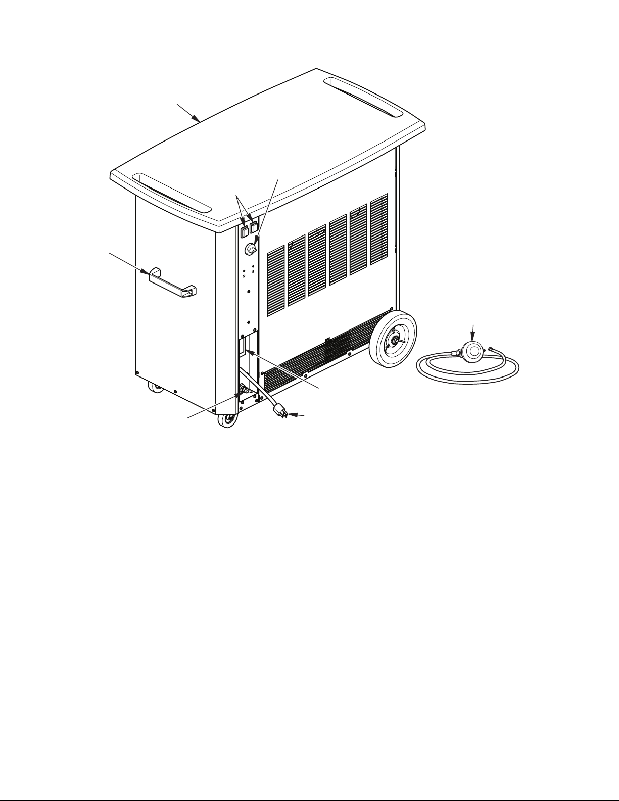
Figure 1 - Tent Heater
Top
Power Cord
Hose and
Regulator
Assembly
Gas Inlet
Handle
Thermostat
Knob
ON/OFF
Switches
Receptacle
PROPANE SUPPLY
PRODUCT IDENTIFICATION
1. The amount of propane gas in tank(s)
2. The temperature of tank(s)
The following chart shows the number of
100 lb. (45 kg) tanks needed to run this
heater.
Smaller tanks can be used for limited run
times but it is recommended to use larger
tanks for optimum performance.
Average Temperature Number Of Tanks
At Tank (100 lb/45 kg)
Above 20° F (-6.7° C) 2
20° F (-6.7° C) to 0° F (-18° C) 3
Below 0° F (-18° C) Use larger tank
Less gas is vaporized at lower temperatures.
You may need two or more 100 lb. (45 kg)
tanks or one larger tank in colder weather.
Your local propane gas dealer will help you
select the proper supply system. The minimum surrounding air temperature rating for
each heater is -20° F (-29° C).
Propane/LP gas and propane tank(s) are to
be furnished by the user.
Use this heater only with a propane vapor
withdrawal supply system. See Chapter 5
of the Standard for Storage and Handling
of Liqueed Petroleum Gas, ANSI/NFPA 58
and the Natural Gas and Propane Installation
Code CSA B149.1. Your local library or re
department will have this booklet.
Keep propane/LP tank(s) at least 5 ft away
from the side of the tent.
The propane/LP tank(s) shall be protected
from vehicles and secured in accordance
with the Standard for Grandstands, Folding
and Telescopic Seating, Tents and Membrane
Structures NFPA 102 and the Standard for
Storage and Handling of Liquieed Petroleum
Gases ANSI/NFPA 58.
The amount of propane gas ready for use
from propane tanks varies. Two factors decide
this amount:
Page 7
www.desatech.com
120193-01A 7
UNPACKING
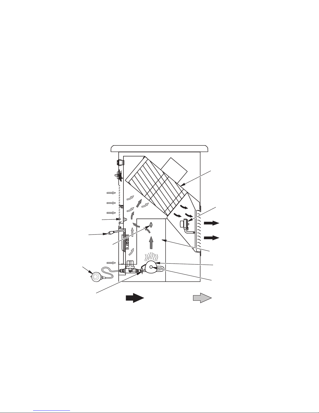
Figure 2 - Cross Section Operational View
Clean
Heated
Air Out
(Front)
Combustion Chamber
Hose/Regulator
Assembly
Injector
Motor and
Blower
Assembly
Cool
Air In
(Back)
Power Cord
Fuel
DSI
Air for Fuel
System
Thermal Switch
Ignitor, Flame
Sensor and ODS
Burner
Air Pressure Switch
1. Remove all packing items applied to
heater for shipment. Keep plastic cover
caps (attached to inlet connector and
hose/regulator assembly) for storage.
2. Remove all items from carton.
3. Check all items for shipping damage. If
heater is damaged, promptly inform dealer
where you bought heater.
THEORY OF OPERATION
The Fuel System: The hose/regulator assembly attaches to the propane gas supply. The
propane gas moves through the automatic control valve and out the injector.
The Air System: The motor turns the fan. The fan pulls air into and around the combustion
chamber. This air is heated and provides a stream of clean, hot air.
The Ignition System: The direct spark ignitor (DSI) sends voltage to the spark ignitor. The
spark ignitor ignites the fuel and air mixture.
The Safety Control System: There are 4 independent systems:
1. Flame Sensor: This system causes the heater to shut down if the ame goes out.
2. Thermal Switch: This system causes the heater to shut down if the heater gets too hot
(blocked openings).
3. Air Pressure Switch: The system will not allow the heater to start if there is not adequate
air ow.
4. ODS - Oxygen Depletion System: This system shuts down the heater if the oxygen level
drops below the specied level (18%).
ODS Operation: Burner porting "blows" out causing ame sensor to cool, shutting down heater.
Page 8
www.desatech.com
120193-01A8
ASSEMBLY
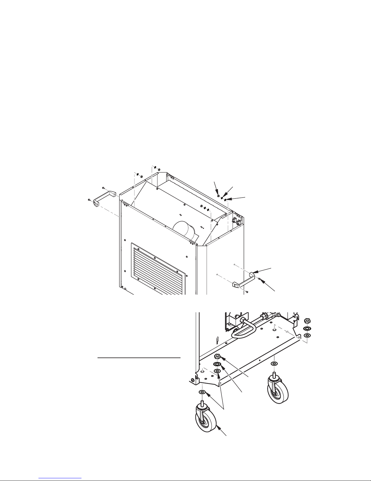
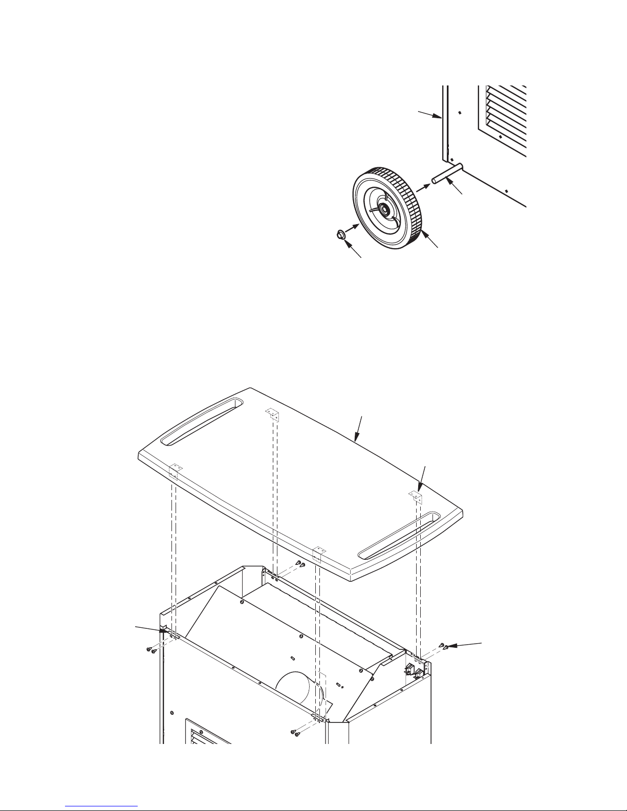
Figure 3 - Attaching Handles
Handle
Screw
Nut
Lock Washer
Figure 4 - Installing Casters
Nut
Flat Washer
Caster
ASSEMBLY ITEMS
Before assembling heater, make sure you have the items listen below.
• Phillips head screwdriver
• Wrench
• Hardware packet
Handles (2), 3/4" Screws (4), 1/4-20 Nuts (4), 1/4 Flat washers (4), 1/4 Lock washers (4)
Casters (2), 3/8" Nut (2), 3/8 Lock washers (2), 3/8 Flat Washers (4)
Wheels (2), Push Caps (2)
Brackets (4), 1/2" black screws (8), 3/8" screws (8)
Note: Place metal parts on packaging during assembly to protect from scratches.
Casters
1. Remove casters, 3/8 at washers, 3/8
lock washers and 3/8 nuts from hardware
packet.
2. You may wish to remove side panel from
heater to make installing casters easier.
If so, see Top and Side Panel Removal
on page 13. Figure 4 shows side panel
removed for clarity.
3. Use a spacer to prop end of heater up
so holes in base can be accessed (the 2
wheels stacked on top of each other will
accomplish this).
4. Place a at washer onto threaded stem of
caster. Insert caster stem through hole in
cabinet base as shown in Figure 4.
5. Attach each caster to base with a at
washer, a lock washer and a nut as shown
in Figure 4.
Side Handles
1. Remove handles, 3/4" screws, 1/4-20
nuts, 1/4 at washers and 1/4 lock washers from hardware packet.
2. Attach each handle to side panels with 2
screws, 2 nuts, 2 at washers and 2 lock
washers. Insert screw from outside of
heater and through handle. From inside
of heater, attach a at washer, then a lock
washer then a nut as shown in Figure 3.
Flat Washer
Lock Washer
Page 9
www.desatech.com
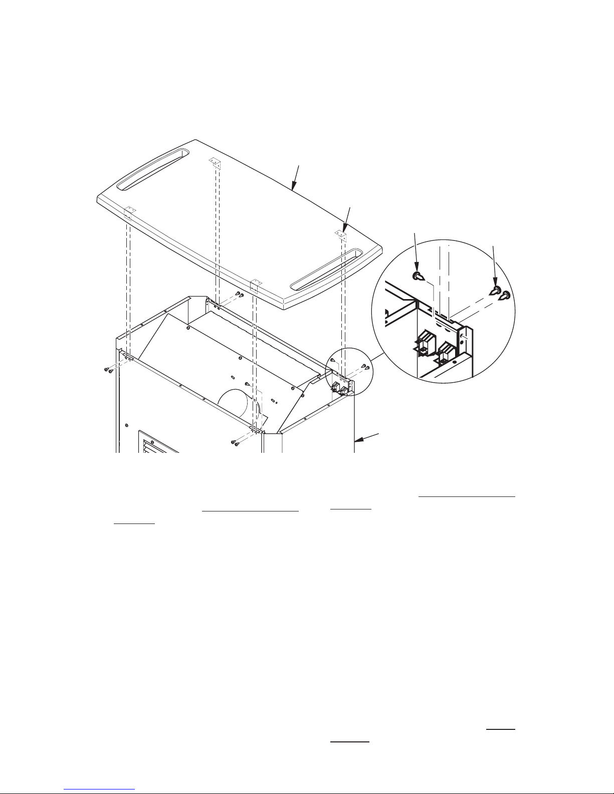
120193-01A 9
Bracket
Top
Bracket
Screws
Figure 6 - Attaching Top
ASSEMBLY
Continued
Figure 5 - Installing Axle and Wheels
Heater
Front
Axle
Wheel
Push Cap
Wheels and Axle
1. Locate wheels and axle in packaging.
Remove 2 push caps from hardware
packet.
2. Stand axle upright placing one end on the
oor. Gently tap one push cap onto end
of axle.
3. Slide one wheel onto axle then carefully
slide axle through heater body as shown
in Figure 5.
4. Slide second wheel onto axle from opposite side of heater.
5. Have another person secure wheel and
axle from other side of heater while gently
tapping second push cap onto end of
axle.
Top
1. Remove 4 brackets, (8) 1/2" black screws
and (8) 3/8" screws from hardware
packet.
2. Lay top upside down on a clean surface.
Attach 4 brackets to top with 1/2" black
screws.
3. Turn top over and carefully place over
heater, positioning brackets through slots
in heater front and rear panels.
4.
Attach brackets to heater with 3/8" screws.
Bracket
Slots
Page 10
www.desatech.com
120193-01A10
INSTALLATION
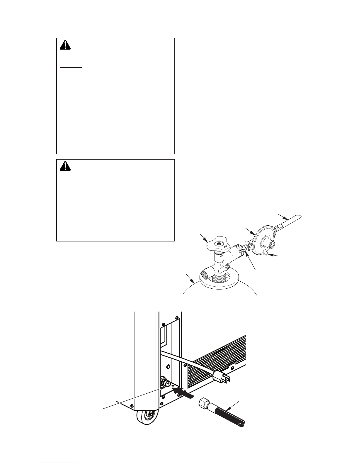
2. Connect fuel gas connector fitting on
hose/regulator assembly to propane
tank(s) (see Figure 7). Turn counterclockwise into threads on tank valve. Tighten
rmly using wrench.
IMPORTANT: Tighten regulator with vent
pointing down. Pointing vent down protects regulator from weather damage.
3. Connect hose to inlet connector (see
Figure 8). Tighten rmly using a wrench.
IMPORTANT: Extra hose or piping may be
used if needed. Install extra hose or piping
between hose/regulator assembly and
propane tank. You must use the regulator
supplied with heater.
4. Open propane supply valve on propane
tank(s) slowly.
Note: If not opened slowly, excess ow
check valve on propane tank will stop gas
ow. If this happens, close propane supply
valve and open again slowly.
5. Check all connections for leaks. Correct
all leaks.
Figure 7 - Regulator With Vent Pointing
Down
Hose
Regulator
Vent
(pointing
down)
Fuel Gas
Connector
Supply Valve
Propane
Tank
Figure 8 - Hose and Inlet Connector
Hose
Inlet
Connector
WARNING: Review and un-
derstand the warnings in the
Safety section, page 2. They are
needed to safely operate this
heater. Follow all local codes or
in the absence of local codes,
with the Standard for Grand-
stands, Folding and Telescopic
Seating, Tents and Membrane
Structures NFPA 102 and the
Standard for Storage and Han-
dling of Liquieed Petroleum
Gases ANSI/NFPA 58.
WARNING: Test all gas piping
and connections for leaks after
installation or servicing. Never
use an open ame to check for a
leak. Apply a noncorrosive leak
detection uid to all joints (available at local plumbing supply
stores). Bubbles forming show a
leak. Correct all leaks at once.
1. Provide propane supply system (see
Propane Supply, page 6).
Page 11
www.desatech.com
120193-01A 11
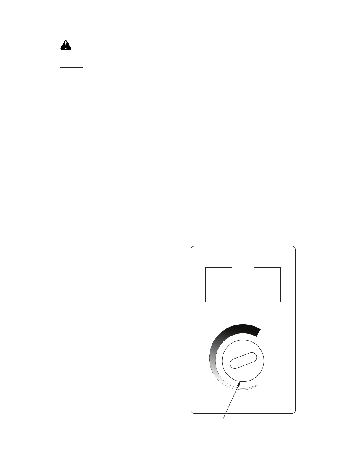
OPERATION
CONTINUOUS FAN WITH HEAT
1. Press Switch 1 to ON.
2. Press Switch 2 to ON.
3. Adjust thermostat knob to desired
comfort level.
Note: Fan will stay on when burner cycles off.
FAN ONLY WITH NO HEAT
1. Turn gas supply off.
2. Press Switch 1 to OFF.
3. Press Switch 2 to ON.
4. Adjust thermostat knob to Fan Only
position.
TO STOP HEATER
1. Tightly close propane/LP supply valve on
propane tank(s).
2. Wait a few seconds. Heater will burn gas
left in supply hose.
3. Press on/off switches to the OFF position.
4. Unplug heater.
TO RESTART HEATER
1. Press on/off switches to the OFF position.
2. Reconnect extension cord.
3. Turn on gas supply valve.
4. Follow To Start Heater instructions, col-
umn 1.
Thermostat
Fan Cycle
ON
OFF
Switch 1
Fan
Continuous
ON
THERMOSTAT
CYCLE
LOW
Fan Only
HIGH
OFF
Switch 2
8
1
2
3
4
5
6
7
Thermostat Knob
Figure 9 - Control Panel
WARNING: Review and un-
derstand the warnings in the
Safety section, page 2. They are
needed to safely operate this
heater. Follow all local codes
when using this heater.
TO START HEATER
1. Follow all installation, ventilation and
safety information.
2. Connect regulator/hose assembly to gas
supply.
3. Check for leaks using a noncorrosive leak
detection uid. Bubbles forming indicate a
gas leak. Correct all leaks before attempting to operate heater.
4. Locate heater on a stable and level surface. Make sure strong drafts do not blow
into front or rear of heater.
5. Plug power cord of heater into a three
prong, grounded extension cord. Extension cord must be at least 6 feet (1.83 m)
long, CSA listed and of proper size.
Extension Cord Size Requirement
Up to 100 ft. (30 m) long, use 16 AWG
rated cord.
101 to 200 ft. (31 to 60 m) long, use 14
AWG rated cord.
6. Plug extension cord into a 120v/60 hz,
three hole, grounded GFI outlet.
7. Open gas supply valve slowly.
Note: If heater burner does not ignite,
turn gas supply off and open slowly. The
hose/regulator assembly is equipped with
an excess ow safety valve. An audible
"click" is heard when opened too fast.
8. Choose desired function:
THERMOSTAT OPERATION WITH HEAT
1. Press Switch 1 to ON.
2. Press Switch 2 to OFF.
3. Adjust thermostat knob to desired
comfort level.
Note: Fan will cycle on and off with burner.
Page 12
www.desatech.com
120193-01A12
STORAGE
2. Place plastic cover caps over brass ttings
on inlet connector and hose/regulator assembly.
3. Store in dry, clean, and safe place.
4. When taking heater out of storage, always
check inside of heater. Insects and small
animals may place foreign objects in
heater. Keep inside of heater free from
combustible and foreign objects.
CAUTION: Disconnect heater
from propane supply tank(s).
1. Store propane tank(s) in safe manner. See
Chapter 5 of Standard for Storage and
Handling of Liqueed Petroleum Gases,
ANSI/NFPA 58 and the Natural Gas and
Propane Installation Code CSA B149.1.
Follow all local codes. Always store propane tanks outdoors.
MAINTENANCE
WARNINGS
• Never service heater while it
is plugged in, connected to
propane supply, operating, or
hot. Severe burns and electrical shock can occur.
• Keep heater clear and free
from combustible materials,
gasoline, and other ammable
vapors and liquids.
• Do not block the ow of combustion or ventilation air.
1. Keep heater clean. Clean heater annually
or as needed to remove dust and debris. If
heater is dirty or dusty, clean heater with
a damp cloth. Use household cleaners on
difcult spots.
2. Inspect heater before each use. Check
connections for leaks. Apply a noncor-
rosive leak detection uid to connections.
Bubbles forming show a leak. Correct all
leaks at once.
3. Inspect hose/regulator assembly before
each use. If hose is highly worn or cut,
replace with one specied by manufacturer.
4. Have heater inspected yearly by a quali-
ed service agency.
5. Keep inside of heater free from combus-
tible and foreign objects. Remove motor
and other internal parts if needed to clean
inside of heater (see Service, below).
Burner
Check burner air inlet after every 300 hours
of operation to ensure burner air inlet is free
of dust or debris. Use compressed air (30 PSI
or less) to clean out burner air inlet.
SERVICE
WARNING: Never service
heater while it is plugged in,
connected to propane supply,
operating, or hot. Severe burns
and electrical shock can occur.
IMPORTANT: CHECK FOR GAS LEAKS. Test
all gas piping and connections for leaks after
installation or servicing. Never use an open
ame to check for a leak. Apply a noncorrosive
leak detection uid to all joints (available at local plumbing supply stores). Bubbles forming
show a leak. Correct all leaks at once.
Page 13
www.desatech.com
120193-01A 13
SERVICE
Continued
ELECTRICAL AND GAS TRAIN
COMPONENT ACCESS
1. Remove top (see Top and Side Panel
Removal, above).
2. Locate wiring diagram on inside of side
panel or go to page 19.
3. Check that all wiring terminals are securely connected.
4. Check for gas leaks around ttings and
tubing of plumbing connections. See
page 10.
TOP AND SIDE PANEL REMOVAL
1. Remove 8 screws securing top brackets
to body panels. Remove top and set aside
(see Figure 10).
Brackets
Located
Underneath
Figure 10 - Removing Top and Side Panel
Side
Panel
Top
Bracket
Screws
Side Panel
Screw
2. Remove 2 screws securing side panel
at top edge. Remove 3 screws at lower
outside edge (see Figure 10). Push down
and lift out side panel.
MOTOR AND BLOWER ASSEMBLY
1. Remove top (see Top and Side Panel
Removal, above).
2. Remove 4 screws securing outlet louver
to front panel (see Figure 11, page 14).
3. Follow wires from blower/motor and disconnect from terminal blocks. Pull wires
out and coil excess to prevent damage to
insulation.
4. Remove 9 screws securing blower mount-
ing panel (see Figure 11, page 14). Bend
bafe top up and carefully lift entire as-
sembly out of heater.
5. Remove 4 nuts securing blower/motor to
mounting panel.
6. Attach new blower/motor to mounting
panel and reinstall in reverse order. Use
care when removing or installing blower
to mounting panel to avoid damage to
wiring. Reattach wiring referring to Wiring
Diagram on page 19.
Page 14
www.desatech.com
120193-01A14
Outlet Louver
Figure 11 - Removing Blower/Motor Assembly
Terminal
Blocks
Blower/Motor
Blower
Mounting
Panel
Bafe Top
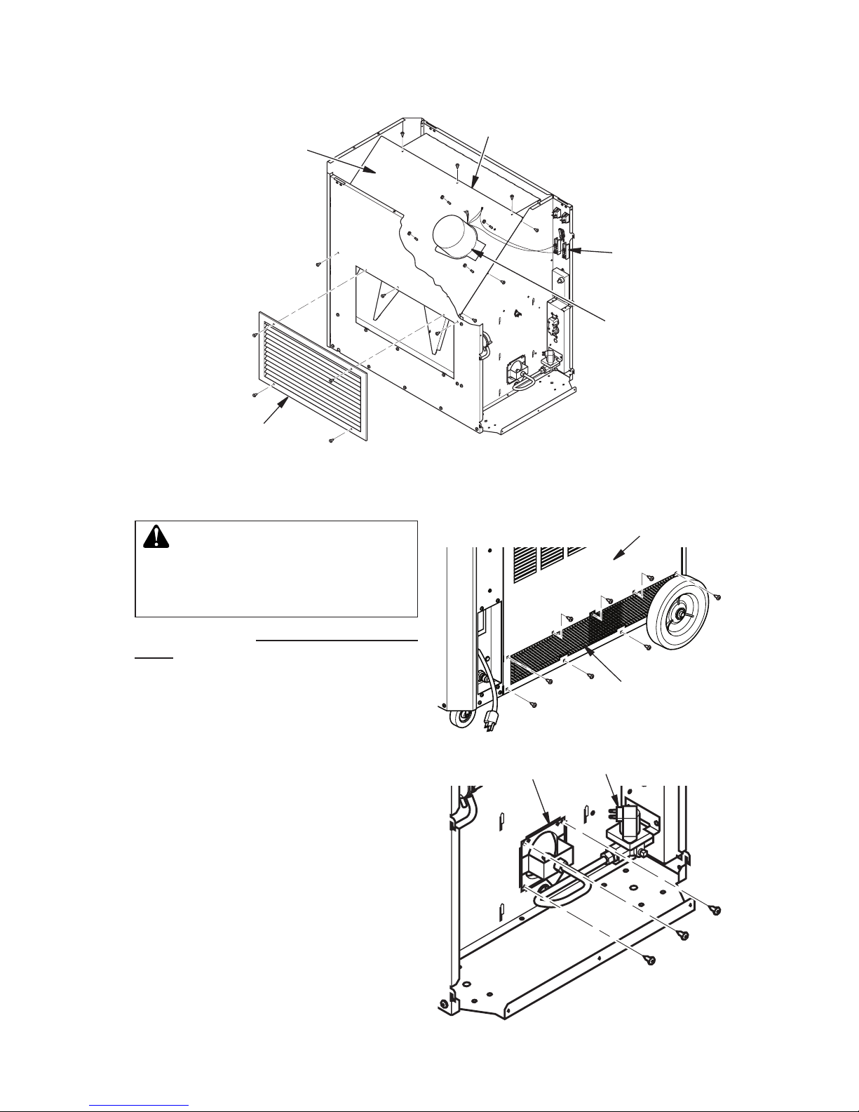
Figure 12 - Back Panel and Screen
Figure 13 - Removing Burner
Burner
Solenoid Valve
Back Panel
Screen
BURNER, IGNITOR AND GAS
ORIFICE
WARNING: Make sure heater
is disconnected from propane and
electrical supply. Heater could
ignite causing severe burns.
Remove top (see Top and Side Panel Removal, see page 13).
Replacing Burner
1. Remove all visible screws from lower section of back panel and screen (see Figure
12). Pull back panel out to gain access to
screen. Push screen up and over ange,
then slide out.
2. Disconnect orange ignitor wire from ignitor. Ignitor is attached to back of burner.
3. Disconnect gas line at solenoid valve
and at orice using a 5/8" wrench. Avoid
bending and set aside.
4. Remove 3 screws securing burner to
partition (see Figure 13). Rotate burner
clockwise and pull out of chamber.
Note: There is a cutout on the partition
that allows the ignitor and bracket to slide
out as a complete assembly. Use caution
when removing or installing burner to avoid
damaging or dislocating ignitor electrode.
5. After all service is complete, reinstall
burner in reverse order. Support burner
SERVICE
Continued
while inserting burner locator pin into hole
in chamber end panel. Replace screen
and back panel.
Page 15

www.desatech.com
120193-01A 15
Replacing Ignitor
1. To loosen back panel and gain access
to ignitor, follow step 1 under Replacing
Burner, page 14.
2. Remove ignitor bracket screw and lift
ignitor.
3. Attach new ignitor with ignitor mounting
screw removed in step 2.
4. Install new ignitor. Ignitor gap between
ignitor electrode and burner deck is
0.13"/0.15" (3.3/3.8 mm).
5. Test for spark. Plug into extension cord
and watch for spark between ignitor
electrode and burner deck.
SERVICE
Continued
Ignitor Gap
Figure 14 - Ignitor Gap
Replacing Gas Orice
1. Hold burner flange and rotate orifice
counterclockwise to remove.
2. Install new orice
IMPORTANT: CHECK FOR GAS LEAKS. Test
all gas piping and connections for leaks after
installation or servicing. Never use an open
ame to check for a leak. Apply a noncorrosive
leak detection uid to all joints (available at local plumbing supply stores). Bubbles forming
show a leak. Correct all leaks at once.
REPLACING DSI CONTROL
1. Remove top (see Top Panel Removal,
page 13).
2. Disconnect orange ignitor wire.
3. Remove white wire connector.
4. Remove 2 screws and nuts securing DSI
control.
5. Install new DSI control. Reconnect wiring.
REPLACING GAS VALVE
1. Remove top (see Top and Side Panel
Removal, page 13).
2. Disconnect 2 blue wires.
3. Remove gas line.
4. Remove 2 screws and nuts holding valve
to mounting plate.
5. Remove brass ttings from old gas valve.
If damaged replace with new fittings.
Install ttings into new gas valve. Use
pipe joint sealant that is resistant to liquid
petroleum (LP) gas. Tighten all ttings.
6. Install new gas valve using screws and
nuts from step 4.
7. Connect blue wires to new gas valve.
8. Reconnect gas line.
IMPORTANT: CHECK FOR GAS LEAKS. Test
all gas piping and connections for leaks after
installation or servicing. Never use an open
ame to check for a leak. Apply a noncorrosive
leak detection uid to all joints (available at local plumbing supply stores). Bubbles forming
show a leak. Correct all leaks at once.
CHECKING REGULATOR
PRESSURE
1. Remove top (see Top Panel Removal,
page 13).
2. Locate pressure tap on solenoid valve and
remove (retain plug for later installation).
See Figure 15, page 16.
3. Install 1/8 NPT barb tting with sealant on
threads into solenoid valve.
4. Connect to manometer or pressure gauge
that measures in inches of water.
5. Connect hose and regulator to heater and
tank.
6. Plug in and turn on.
Page 16
www.desatech.com
120193-01A16
SPECIFICATIONS
• Output Rating - 125,000 Btu/Hr (131,882 kJ/Hr)
• Fuel Consumption - 1.4 Gal/Hr (5.2 Liters/Hr), 5.8 lb/Hr (2.6 kg/Hr)
• Propane Vapor Fuel Only
• Manifold Pressure - 10" (25.4 cm) WC
• Supply Pressure To Regulator: Minimum (for purposes of input adjustment) 10 psi (69 kPa),
Maximum - Tank Pressure
• Regulator Outlet Pressure - 11" wc
• Electric Input - 120 V/60 Hz
• Amperage - Start 7, Run 3.5
• Load - 10 amps on receptacle
• Hot Air Output (Approx) - 1000 CFM (28.3 m3/min)
• Motor - 1,100 RPM, 1/4 HP
• Ignition - Electronic Direct Spark Ignition (D.S.I.)
• Ignitor Gap - 0.12"/0.15" (3.1/3.8 mm)
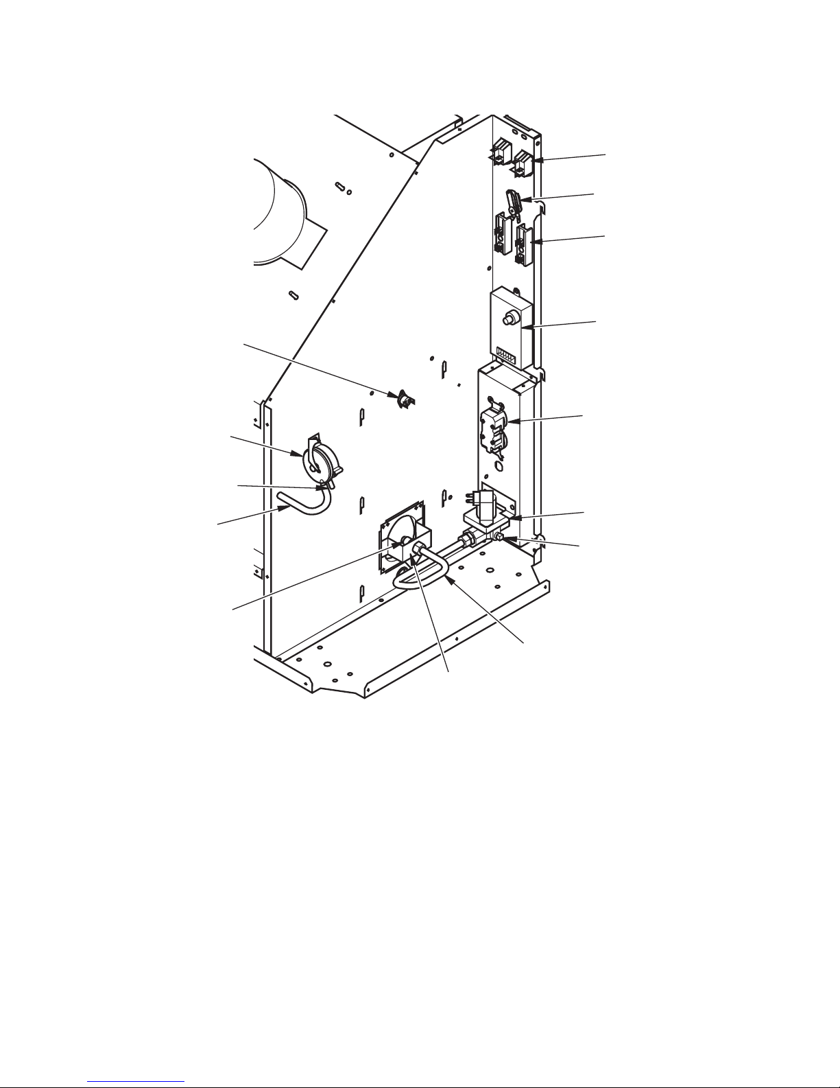
Figure 15 - Tent Heater Parts
Solenoid
Valve
Receptacle
DSI
Terminal
Boards
Thermostat
Switches
Gas Line
Burner
Pressure
Switch
SERVICE
Continued
Vacuum
Pressure
Pressure
Tap
Thermal
Limit Switch
Injector
Page 17
www.desatech.com
120193-01A 17
REMEDY
1. Check voltage to electrical
outlet. If voltage is good,
check heater power cord for
breaks
2. Adjust thermostat to higher
setting
3. Wait for ambient temperature
to decrease
4. Replace motor. See Motor and
Blower Assembly, page 13
1. Repeat installation and operation instructions. See
Installation, page 10 and
Operation, page 11
2.
A) Check ignitor wire. Tighten
or reattach loose ignitor wire.
B) Assure gap between ignitor
electrode and burner deck is
0.13"/0.15" (3.3/3.8 mm). Do
not bend electrode. Doing so
may cause it to break
C) Replace ignitor elec-
trode. See Replacing Ig-
nitor, page 15
D) Replace spark trans-
former. See Replacing DSI
Control, page 15
3. Clean tubing
POSSIBLE CAUSE
1. No electrical power to heater
2. Thermostat set too low
3. Ambient temperature is too
high. Thermostat is satis-
ed
4. Defective motor
1. User did not follow installation or operation instructions
properly
2. No spark at ignitor. To test
for spark, follow step 5 under
Replacing Ignitor, page 15. If
you see spark at ignitor, have
heater serviced by qualied
service person. If no spark
seen:
A) Loose or disconnected
ignitor wire
B) Wrong spark gap
C) Bad ignitor electrode
D) Bad spark DSI
3. Air proving switch blocked
OBSERVED FAULT
Fan does not turn when
switch(s) 1 or 2 are pressed
to ON
Heater will not ignite
TROUBLESHOOTING
WARNING: Never service heater while it is plugged in, connected
to propane supply, operating, or hot. Severe burns and electrical
shock can occur.
Page 18
www.desatech.com
120193-01A18
WARNING: Use only in areas
free of high dust content.
TROUBLESHOOTING
Continued
REMEDY
1. A) Rell tank
B) Provide additional and/or
larger tanks. See Propane
Supply, page 6
2. This can happen when running
heater in temperatures above
85° F (29˚ C). Run heater in
cooler temperatures
3. Check heater inlet and outlet.
Remove any obstructions
4.
Replace motor and blower assembly. See page 13
5. Clean heater. See Mainte-
nance, page 12
1. Check all connections for
leaks. Apply noncorrosive leak
detection uid to gas joints.
Bubbles forming show a leak
that must be corrected
2. To obtain correct mixture of
propane/LP gas and air, use
a larger cylinder size, i.e.
100 lb. See Propane Supply,
page 6
3. Use a larger supply cylinder
size, i.e. 100 lb.
POSSIBLE CAUSE
1. Propane supply may be
inadequate
2. High surrounding air temperature causing thermal
limit device to shut down
heater
3. Restricted air ow
4. Damaged fan
5. Excessive dust or debris in
surrounding area
1. Gas leak
2. Heater operating on a 20 lb.
propane/LP cylinder. Insuf-
cient propane/LP gas will be
supplied by a 20 lb. cylinder
resulting in odor
3. Propane/LP supply tank is
"freezing up". Evaporation
and consumption rate of
propane/LP from supply tank
is to great for the size of the
tank and air temperature
OBSERVED FAULT
Heater shuts down while
running
Heater producing odor
TECHNICAL SERVICE
You may have further questions about
this heater. If so, contact DESA Heating
Products’ Technical Service Department
at 1-866-672-6040. When calling, please
have your model and serial numbers of your
heater ready.
You can also visit DESA Heating Products’
Technical Service web site at
www.desatech.com.
Page 19
www.desatech.com
120193-01A 19
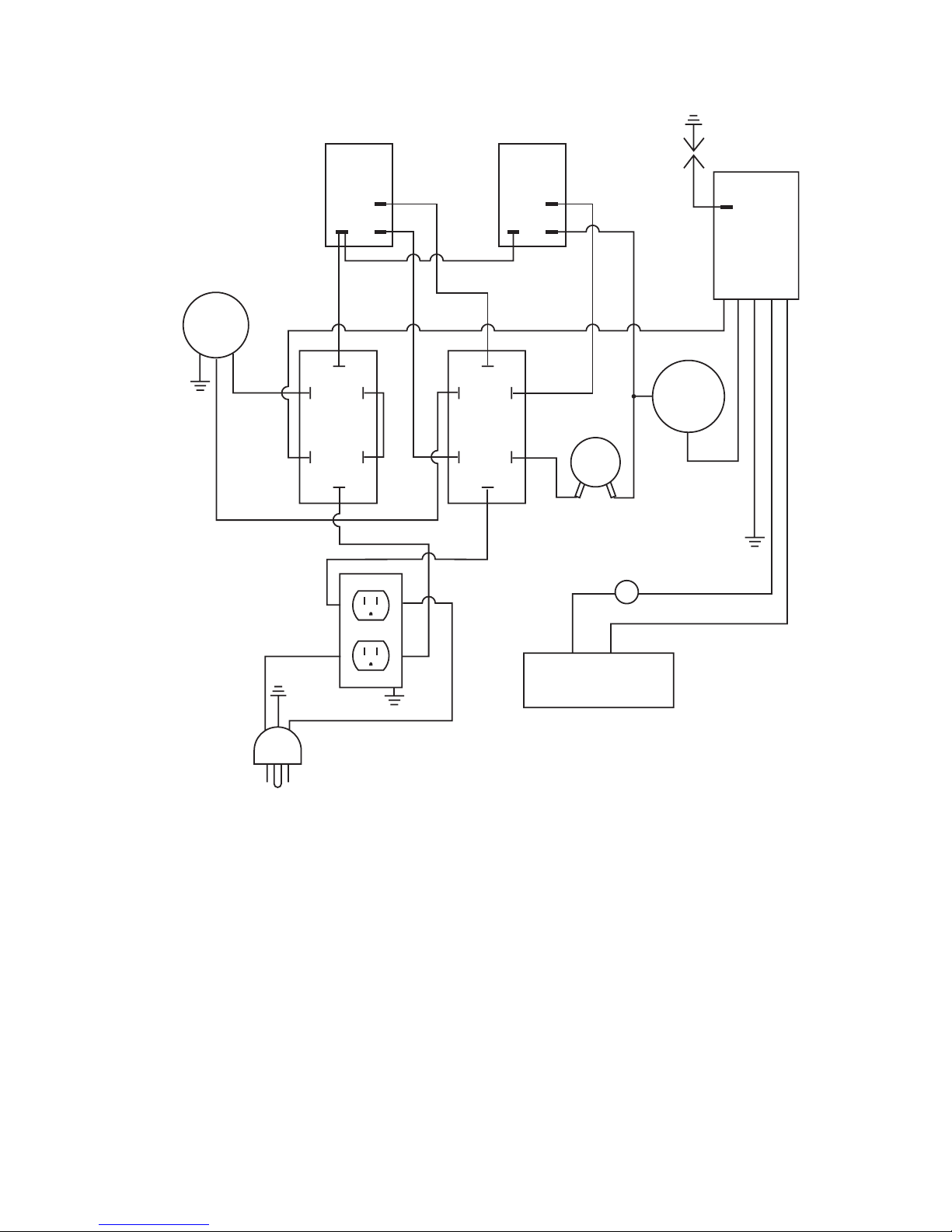
WIRING DIAGRAM
Electrical Connection Diagram
Motor
Moteur
VAC
Switch
(4)
Thermostat
Termostato
Receptacle
(6)
Switch 1
Cycle
(1)
White
Blanco/Blanc
White
Blanco/Blanc
White
Blanco
Blanc
White
Blanco
Blanc
White/Blanco/Blanc
White
Blanco
Blanc
White/Blanco/Blanc
Solenoid Valve/
Válvula de solenoide/
Électrovanne
DSI
(encendedor
de chispa
directa)
AED
Black
Negro
Noir
Black
Negro
Noir
Black
Negro
Noir
Black
Negro
Noir
Black
Negro
Noir
Orange
Naranja
Black
Negro
Noir
Green
Verde
Vert
Green
Verde
Vert
Green
Verde
Vert
Green
Verde
Vert
Blue
Azul
Bleu
Blue/Azul/Bleu
Blue/Azul/Bleu
Red/Rojo/Rouge
Red
Rojo
Rouge
Red
Rojo
Rouge
Terminal Block
(3)
Terminal Block
(3)
Switch 2
Continuous
(2)
(1) Interruptor 1 ciclo automático/
Interrupteur 1 en cycle
(2) Interruptor 2 continuo/
Interrupteur 2 en continu
(3) Bloque de terminales/Bornier
(4) Interruptor de VCA/
Interrupteur V c.a.
(5) Interruptor térmico/
Interrupteur thermique
(6) Receptáculo/Prise
Power Cord/
Cable de alimentación/
Cordon électrique
Thermal Switch
(5)
S1 = Switch 1
(1)
S2 = Switch 2
(2)
VAC = VAC Switch
(4)
T/S = Thermal Switch
T = Thermostat
Black
Negro/Noir
Black
Negro/Noir
Black
Negro/Noir
Black
Negro
Noir
T
L1
Page 20
www.desatech.com
120193-01A20
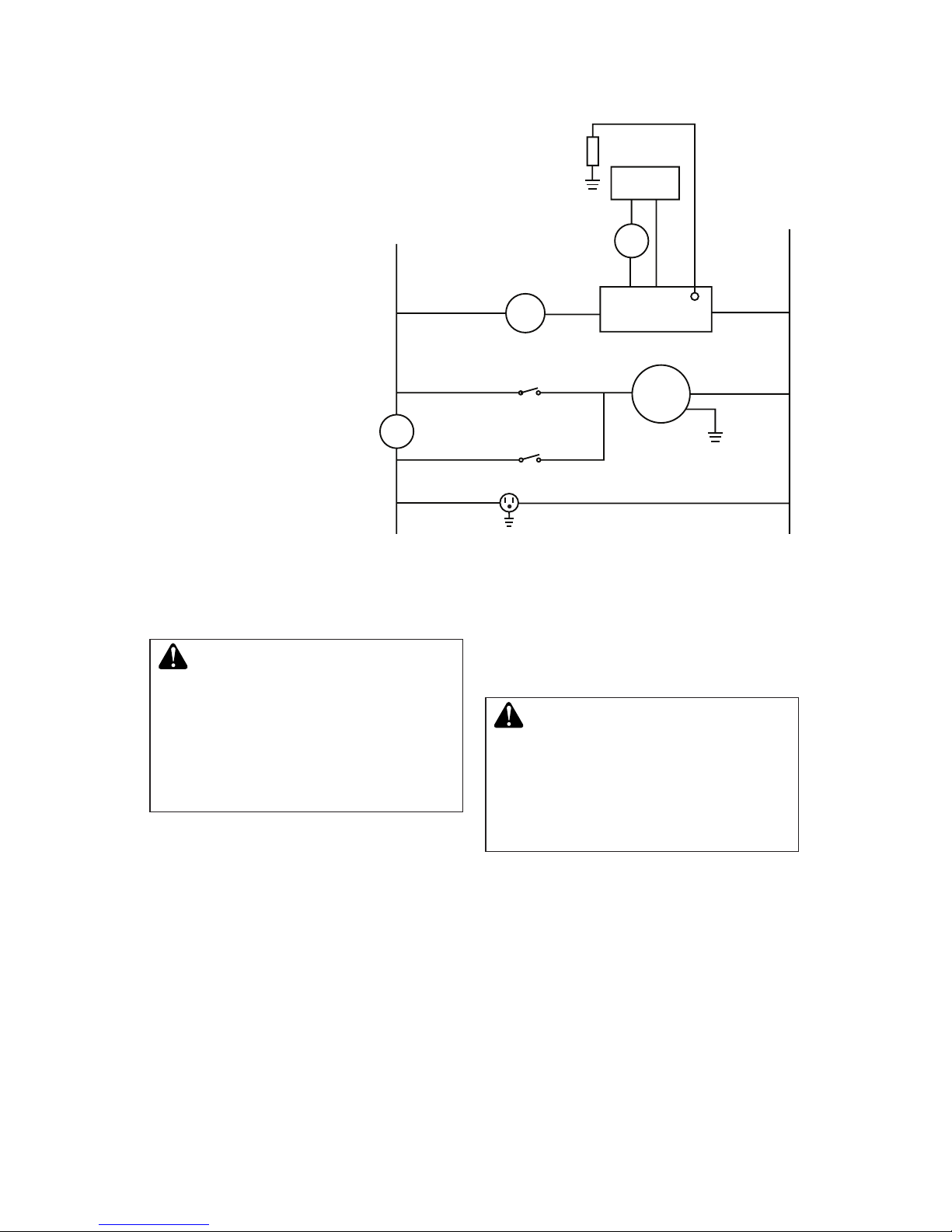
Ladder Diagram
WARNING: Never attempt
to service heater while it is
plugged in, operating, or hot.
Burns and electrical shock could
result. Only a qualied service
person should service or repair
heater.
WIRING DIAGRAM
Continued
If any of the original wire as supplied with
the appliance must be replaced, it must be
replaced with 105° C wire or it’s equivalent.
WARNING: Label all wires
prior to disconnection when
servicing controls. Wiring errors
can cause improper and dangerous operation. Verify proper
operation after servicing.
(1) Interruptor 1 ciclo automático/
Interrupteur 1 en cycle
(2) Interruptor 2 continuo/
Interrupteur 2 en continu
(3) Bloque de terminales/Bornier
(4) Interruptor de VCA/
Interrupteur V c.a.
(5) Interruptor térmico/
Interrupteur thermique
(6) Receptáculo/Prise
Motor
Moteur
White
Blanco/Blanc
White/Blanco/Blanc
S1 = Switch 1
(1)
S2 = Switch 2
(2)
VAC = VAC Switch
(4)
T/S = Thermal Switch
(5)
T = Thermostat
Neutral
Neutro
Neutre
White
Blanco
Blanc
Black
Negro/Noir
Black
Negro/Noir
Black
Negro/Noir
Black
Negro
Noir
Black
Negro
Noir
Blue
Azul
Bleu
Blue/Azul/Bleu
Blue/Azul/Bleu
T
L1
DSI
VAC
S2
Receptacle
(6)
S1
Solenoid
Valve
Ignitor
Encendedor
Allumeur
Orange
Naranja
T/S
L2
Red/Rojo
Rouge
Red
Rojo
Rouge
Page 21
www.desatech.com
120193-01A 21
REPLACEMENT PARTS
WARNING: Use only original
replacement parts. This heater
must use design-specic parts.
Do not substitute or use generic
parts. Improper replacement
parts could cause serious or fatal injuries. This will also protect
your warranty coverage for parts
replaced under warranty.
PARTS UNDER WARRANTY
Contact authorized dealers of this product.
If they can’t supply original replacement
part(s), call DESA Heating Products at
1-866-672-6040.
When calling DESA Heating Products, have
ready
• your name
• your address
• model number of your heater
• how heater was malfunctioning
• purchase date
In most cases, we will ask you to return the
part to the factory.
PARTS NOT UNDER WARRANTY
Contact authorized dealers of this product.
If they can’t supply original replacement
part(s), call DESA Heating Products at
1-866-672-6040.
When calling DESA Heating Products, have
ready:
• model number of your heater
• the replacement part number
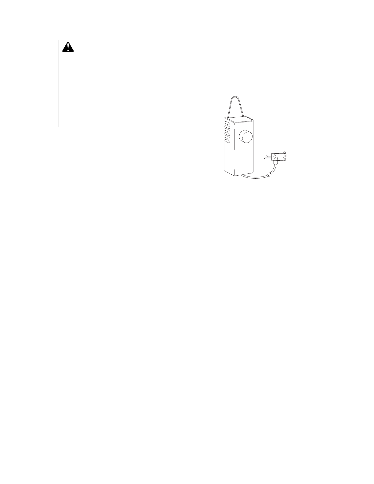
ACCESSORY
Purchase accessories and parts from your
nearest dealer or service center. If your dealer
or service center can not supply an accessory
or part, call DESA Heating Products’ Parts
Department at 1-866-672-6040. You can also
write to the address listed on the back page
of this manual.
THERMOSTAT KIT - PP235
Keeps your building at the temperature you
select day and night. Helps economize on
fuel. Includes 25 ft. cord.
Page 22
www.desatech.com
120193-01A22
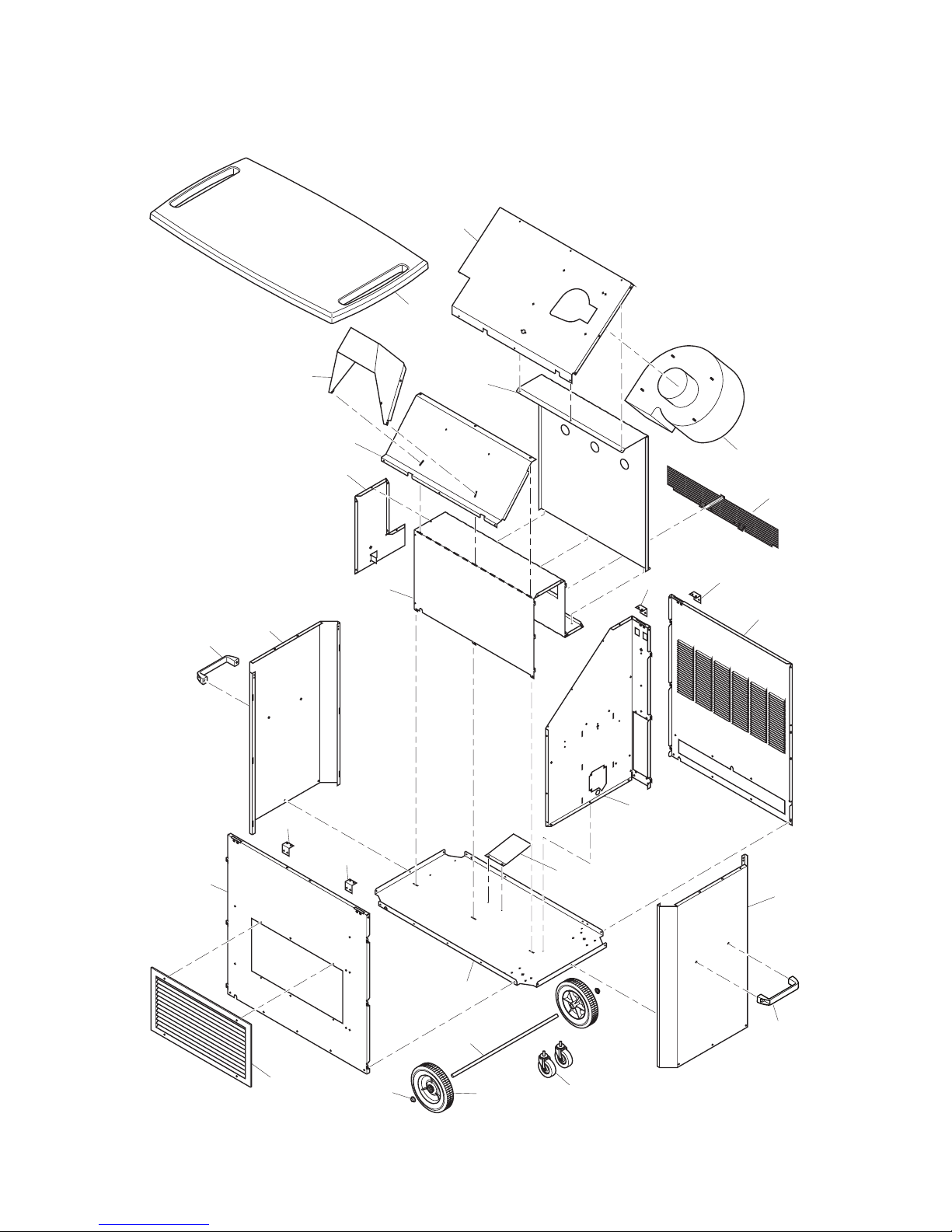
PARTS
CABINET
MODELS TB116, TB117 AND TB118
16
17
18
14
15
7
2
6
5
9
13
19
22
20
21
8
4
3
11
1
12
14
15
10
10
10
10
Page 23
www.desatech.com
120193-01A 23
KEY
NO. PART NO. DESCRIPTION QTY
1 119551-01 Cabinet Top, White • 1
119551-02 Cabinet Top, Black • 1
119551-03 Cabinet Top, Tan • 1
2 119555-01 Blower Mounting Panel • • • 1
3 119753-01 Motor and Blower Assembly • • • 1
4 119640-01 Bafe • • • 1
5 118295-01 Outlet Duct • • • 1
6 119558-01 Lower Bafe • • • 1
7 120043-01 Chamber End Panel • • • 1
8 120042-01 Top Chamber • • • 1
9 120123-01 Screen • • • 1
10 120116-01 Bracket • • • 4
11 118287-01AC Back Panel, White • • 1
118287-02DG Back Panel, Tan • 1
12 118289-01 Partition Panel • • • 1
13 120126-01 Ignitor Reector • • • 1
14 119926-01AC End Panel, White • • 2
119926-02DG End Panel, Tan • 2
15 120111-01 Handle • • • 2
16 118286-01 Cabinet Base • • • 1
17 118294-01AC Front Panel, White • • 1
118294-02DG Front Panel, Tan • 1
18 119553-01 Louvered Outlet Duct • • • 1
19 M16801-12 Plated Axle • • • 1
20 120469-01 Wheel • • • 2
21 M28526 Push cap • • • 2
22 120201-01 Caster • • • 2
PARTS AVAILABLE - NOT SHOWN
Decals Available • • •
120425-01 Hardware Bag • • • 1
110267-01 D.S.I. Wire Harness • • • 1
120173-01 Wire Assembly • • • 1
120173-02 Wire Assembly • • • 1
097806-04 Ignitor Cable • • • 1
098219-44 Power Cord • • • 1
** Not a eld replaceable part.
PARTS
CABINET
This list contains replaceable parts used in your heater. When ordering parts, follow the
instructions listed under Replacement Parts on page 21 of this manual.
TB116
TB117
TB118
Page 24
www.desatech.com
120193-01A24
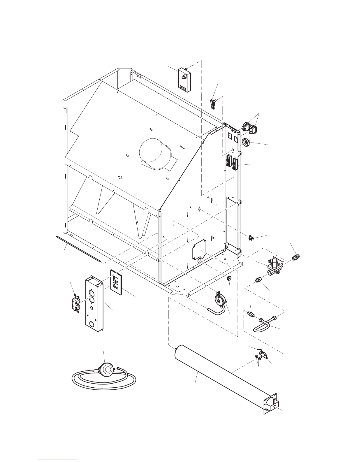
PARTS
MODELS TB116, TB117 AND TB118
17
21
11
10
16
13
12
14
9
8
7
22
2
4
3
19
1
18
20
5
15
6
Page 25

www.desatech.com
120193-01A 25
KEY
NO. PART NO. DESCRIPTION QTY
1 M51605-05 D.S.I. Control • • • 1
2 104458-01 Thermostat • • • 1
3 108394-01 ON/Off Switch • • • 2
4 104460-01 Thermostat Knob • • • 1
5 099125-01 Terminal Board • • • 2
6 101481-12 Thermal Limit Switch • • • 1
7 M51572-02 Male Connector • • • 1
8 103015-01 Solenoid Valve • • • 1
9 098264-02 Male Connector • • • 1
10 103845-15 Injector • • • 1
11 120127-01 Fuel Tube • • • 1
12 103934-01 Ignitor • • • 1
13 119884-01 Ignitor Bracket • • • 1
14 098249-01 ODS Nut • • • 2
15 118254-01 Burner • • • 1
16 M50104-02 Shorty Bushing • • • 2
17 120095-01 Pressure Switch Assembly • • • 1
18 120276-01 Duplex Cover • • • 1
19 119618-01 Recessed Valve Plate • • • 1
20 103769-01 Duplex Outlet • • • 1
21 120096-01 Air Switch Tube • • • 1
22 078923-04 Regulator and Hose Assembly • • • 1
** Not a eld replaceable part.
PARTS
MODELS TB116, TB117 AND TB118
This list contains replaceable parts used in your heater. When ordering parts, follow the
instructions listed under Replacement Parts on page 21 of this manual.
TB116
TB117
TB118
Page 26

www.desatech.com
120193-01A26
_____________________________________________________
______________________________________________________
______________________________________________________
______________________________________________________
______________________________________________________
______________________________________________________
______________________________________________________
______________________________________________________
______________________________________________________
______________________________________________________
______________________________________________________
______________________________________________________
______________________________________________________
_____________________________________________________
______________________________________________________
______________________________________________________
______________________________________________________
______________________________________________________
______________________________________________________
______________________________________________________
______________________________________________________
______________________________________________________
NOTES
Page 27

www.desatech.com
120193-01A 27
_____________________________________________________
______________________________________________________
______________________________________________________
______________________________________________________
______________________________________________________
______________________________________________________
______________________________________________________
______________________________________________________
______________________________________________________
______________________________________________________
______________________________________________________
______________________________________________________
______________________________________________________
_____________________________________________________
______________________________________________________
______________________________________________________
______________________________________________________
______________________________________________________
______________________________________________________
______________________________________________________
______________________________________________________
______________________________________________________
NOTES
Page 28

2701 Industrial Drive
P.O. Box 90004
Bowling Green, KY 42102-9004
1-866-672-6040
WARRANTY
KEEP THIS WARRANTY
LIMITED WARRANTIES FOR NEW AND FACTORY
RECONDITIONED PRODUCTS
New Products: DESA Heating, LLC warrants this heater and any parts thereof, to be free of defects
in materials and workmanship for one (1) year from the date of rst purchase, when operated and
maintained in accordance with the manufacturer's instructions. These warranties are extended only to
the original retail purchaser, when proof of purchase is provided.
Factory Reconditioned Heaters: DESA Heating, LLC warrants this factory reconditioned heater and
any parts thereof, to be free of defects in materials and workmanship for thirty (30) days from the date of
rst purchase, when operated and maintained in accordance with the manufacturer's instructions. These
warranties are extended only to the original retail purchaser, when proof of purchase is provided.
This warranty covers only the cost of parts and labor required to restore the product to proper operating
condition. Transportation and incidental costs associated with warranty repairs are not reimbursable
under this warranty.
Warranty service is available only through authorized dealers and service centers.
This warranty does not cover defects resulting from misuse, abuse, negligence, accidents, lack of
proper maintenance, alteration, modication, tampering, contaminated fuels, repair using improper
parts, or repair by anyone other than an authorized dealer or service center. Routine maintenance is
the responsibility of the owner.
THIS EXPRESS WARRANTY IS GIVEN IN LIEU OF ANY OTHER WARRANTY EITHER EXPRESSED
OR IMPLIED, INCLUDING WARRANTIES OF MERCHANTABILITY AND FITNESS FOR A PARTICULAR PURPOSE.
DESA Heating, LLC assumes no responsibility for indirect, incidental or consequential damages. Some
states do not allow the exclusion or limitation of incidental or consequential damages, or limitations or
exclusions may not apply to you. This Limited Warranty gives you specic legal rights and you may also
have other rights which vary from state to state.
Model _____________________________________
Serial No. __________________________________
Date of Purchase ____________________________
82 Akron Road
Toronto, Canada M8W 1T2
416-255-5333
The only warranty applicable is our standard written warranty. We make no other warranty, expressed or implied.
WARRANTY SERVICE
Should your heater require service, return it to your nearest authorized service center. Proof of purchase
must be presented with the heater. The heater will be inspected. A defect may be caused by faulty materials
or workmanship. If so, DESA Heating, LLC will repair or replace the heater without charge.
REPAIR SERVICE
Return your heater to your nearest authorized service center. Repairs not covered by the warranty will be
billed at standard prices. Each Service Center is independently owned and operated. We reserve the right
to amend these specications at any time without notice.
120193-01
Rev. A
11/06
Patent Pending
Page 29

IMPORTANTE: lea y comprenda este manual antes de
ensamblar, encender o dar servicio al calentador. El uso
inadecuado del calentador puede causar lesiones graves. Conserve este manual para referencias futuras.
ADVERTENCIA GENERAL DE PELIGRO:
El incumplimiento de las precauciones e instrucciones
proporcionadas con este calentador puede causar la
muerte, lesiones físicas graves y pérdidas o daños a
propiedades ocasionados por incendios, explosiones,
quemaduras, asfixia, intoxicación con monóxido de carbono y/o electrocución.
Únicamente las personas que puedan entender y seguir
las instrucciones deberán usar o dar servicio a este
calentador.
Si necesita ayuda o información sobre el calentador, por
ejemplo, un manual de instrucciones, etiquetas, etc., comuníquese con el fabricante.
Guarde este manual para referencias futuras.
Para obtener más información visite www.desatech.com
CALENTADOR DE PROPANO
DE AIRE FORZADO PARA
EVENTOS EN CARPAS
MANUAL DEL PROPIETARIO
MODELOS TB116, TB117 Y TB118
125,000 BTU/H
125
TENT
Event
by
Page 30

www.desatech.com
120193-01A2
ADVERTENCIA: si la información contenida en este
manual no se sigue al pie de la letra, se pueden producir un
incendio o una explosión que podrían ocasionar daños a
la propiedad, lesiones personales o la pérdida de la vida.
—
No guarde ni utilice gasolina u otros vapores y líquidos
inflamables cerca de este aparato ni de cualquier otro.
— QUÉ HACER SI PERCIBE OLOR A GAS
• No intente encender ningún aparato.
• No toque ningún interruptor eléctrico; no use ningún teléfono en el edificio.
• Llame inmediatamente a su proveedor de gas desde
el teléfono de algún vecino. Siga las instrucciones
del proveedor de gas.
• Si no puede localizar al proveedor de gas, llame al
departamento de bomberos.
— La instalación y el servicio deben ser realizados por
un instalador capacitado, agencia de servicio o por el
proveedor de gas.
Éste es un calentador de combustión a gas sin ventilación para carpas. Utiliza aire (oxígeno) de la carpa en la
que se instala. Se deben tomar las medidas necesarias
para asegurar que la cantidad de aire para la ventilación
y la combustión sean adecuadas. Proporcione una abertura de al menos 271 cm2 (42 pulgadas2).
TABLA DE CONTENIDO
Seguridad ............................................................ 3
Identicación del producto ................................... 6
Desempaque ....................................................... 6
Ventilación ........................................................... 6
Suministro de propano ........................................ 7
Teoría de funcionamiento .................................... 8
Ensamble............................................................. 9
Instalación ..........................................................11
Funcionamiento ................................................. 12
Almacenamiento ................................................ 13
Mantenimiento ................................................... 13
Servicio .............................................................. 13
Especicaciones ................................................ 17
Solución de problemas ...................................... 18
Servicio técnico ................................................. 19
Diagrama de cableado ...................................... 20
Piezas ................................................................ 22
Piezas de repuesto ............................................ 26
Accesorios ......................................................... 26
Garantía............................................................. 28
Page 31

www.desatech.com
120193-01A 3
SEGURIDAD
Para uso en Canadá
ANSI Z83.7 - 2000
Calentadores de combustión a gas para
construcción
CGA 2.14 - 2000
Calentadores de combustión a gas para
construcción
General
ANSI/NFPA 102
Norma para tribunas en exteriores techa-
das, gradas plegables y telescópicas,
carpas y estructuras con membranas
ANSI/NFPA 58
La edición más reciente de la Norma
para almacenamiento y manejo de gas
licuado de petróleo
ANSI Z223.1/NFPA 54
La edición más reciente del Código nacio-
nal estadounidense de gas combustible
ANSI/NFPA 70
La edición más reciente del Código
nacional estadounidense de electricidad
y el Código canadiense de electricidad,
CSA C22.1 parte 1
El propósito principal de los calentadores para
construcción es proporcionar calefacción temporal en edificios en construcción, remodelación
o reparación. Cuando se usa correctamente, el
calentador proporciona calefacción económica
y segura. Los productos de combustión se ventilan al área que se está calentando.
No podemos prever todos los usos que se les
pueden dar a nuestros calentadores. Consul-
te a las autoridades locales de seguridad
contra incendios si tiene alguna pregunta
acerca del uso de calentadores.
Otras normas rigen el uso de gases combustibles y productos que producen calor para
usos específicos. Las autoridades locales
pueden informarle acerca de éstas.
ADVERTENCIA: cuando la
combustión y la ventilación no
son adecuadas, el calentador
puede emitir cantidades excesivas de monóxido de carbono, un
gas inodoro y venenoso.
No instale el calentador sino hasta que se hayan
tomado todas las previsiones necesarias de combustión y ventilación. Consulte el instructivo impreso que se incluye con el calentador para obtener
información acerca del aire para la combustión y
ventilación. Cuando no se tengan las instrucciones, consulte el código nacional estadounidense
de gas combustible, ANS Z223.1, sección 5.3 o
los códigos locales correspondientes.
ADVERTENCIA: este producto contiene y/o genera químicos
reconocidos por el estado de California como causantes de cáncer o de defectos de nacimiento,
u otros daños reproductivos.
ADVERTENCIA: peligro de
incendio, quemaduras, inhalación
y explosión. Mantenga los combustibles sólidos como mesas,
sillas, materiales de construcción,
papel o cartón, a una distancia segura del calentador tal y como se
recomienda en las instrucciones.
Nunca use el calentador en áreas
en las que haya, o pueda haber,
combustibles volátiles o que se
acumulen en el aire, o bien, productos como gasolina, solventes,
diluyente de pintura, partículas de
polvo o químicos desconocidos.
ADVERTENCIA: no se debe
usar en residencias ni en vehículos recreativos.
El calentador está diseñado y aprobado para
su uso como calentador de carpas en conformidad con estas instrucciones. SI TIENE
PREGUNTAS SOBRE LAS APLICACIONES,
CONSULTE LAS AUTORIDADES LOCALES
DE SEGURIDAD CONTRA INCENDIOS.
El calentador está diseñado para su uso como
calentador para construcción y como calentador de
carpas sin ventilación. El calentador está diseñado
para usarse dentro del espacio que se va a calentar. El calentador utiliza el aire del espacio que está
calentando para la combustión y ventilación.
Normas aplicables:
Para uso en los EE.UU.
ANSI Z83.7 - 2000
Calentadores de combustión a gas para
construcción
CGA 2.14 - 2000
Calentadores de combustión a gas para
construcción
CSA 3.06 - 2006
Calentadores portátiles de combustión a
gas sin ventilación para carpas
Page 32

www.desatech.com
120193-01A4
SEGURIDAD Continuación
Este calentador está equipado con un sistema
de apagado de seguridad con detección de
agotamiento de oxígeno (ODS por sus siglas
en inglés) que está diseñado para apagar
el calentador cuando no hay suficiente aire
fresco.
¡No altere el sistema de segu-
ridad de detección de agota-
miento de oxígeno!
Si el calentador se apaga, no lo vuelva encender hasta que haya entrado aire fresco. Si el
calentador se sigue apagando, haga que lo
reparen. Mantenga limpios el quemador y el
compartimento de control.
PELIGRO: ¡la intoxicación
con monóxido de carbono puede
ocasionar la muerte!
Intoxicación con monóxido de carbono:
los síntomas iniciales de la intoxicación con
monóxido de carbono son semejantes a los
de la gripe, con dolores de cabeza, mareos
y/o náusea. Si usted presenta estos síntomas, es posible que el calentador no esté
funcionando correctamente. ¡Respire aire
fresco inmediatamente! Compruebe que la
ventilación sea adecuada y haga que reparen
el calentador. El monóxido de carbono afecta
más algunas personas que a otras. Las más
afectadas incluyen mujeres embarazadas,
personas con enfermedades del corazón o
de los pulmones o anemia, aquellas bajo la
influencia del alcohol y aquellas a grandes
altitudes.
Propano o gas LP: el propano o gas LP es
inodoro. Al propano o gas LP se le agrega
un agente que tiene olor. El olor le ayuda
detectar las fugas de propano o gas LP. Sin
embargo, el olor que se añade al propano o
gas LP puede desvanecerse, de manera que
puede haber gas propano aún cuando no se
perciba olor.
Asegúrese de leer y comprender todas las
advertencias. Conserve este manual como
referencia. Es su guía para la operación segura y correcta de este calentador.
ADVERTENCIA: no coloque
ropa ni otros materiales inflamables sobre el aparato o cerca
del mismo.
ADVERTENCIA: debido a las
altas temperaturas generadas
por este aparato, éste se debe
colocar fuera de las rutas de
paso y alejado de muebles.
ADVERTENCIA: los niños
pequeños deben estar bajo
estricta supervisión cuando se
encuentren en la misma habitación que el aparato.
ADVERTENCIA: se debe
advertir a niños y adultos sobre
el peligro que presenta la alta
temperatura de la superficie y
deben mantenerse a distancia
para evitar quemaduras o que
la ropa se encienda.
PRECAUCIÓN: cualquier
protección o rejilla de seguridad
que se haya retirado para el
mantenimiento del aparato deberá volverse a colocar antes de
hacer funcionar el calentador.
1. Instale y use el calentador con cuidado.
Siga todas las ordenanzas y los códigos
locales. Cuando no existan reglamentos
y códigos locales, consulte la Norma para
almacenamiento y manejo de gas licuado
de petróleo, ANSI/NFPA 58, el Código
de instalación de gas natural y propano,
CSA B149.1 y la Norma para tribunas en
exteriores techadas, gradas plegables
y telescópicas, carpas y estructuras
con membranas, ANSI/NFPA 102. Éste
proporciona instrucciones acerca del
almacenamiento y el manejo seguro del
propano o gas LP.
2. Use solamente la tensión eléctrica y la
frecuencia que se especifican en la placa
donde aparece al número de modelo. Las
conexiones eléctricas y a tierra del calentador deberán hacerse de acuerdo al
Código eléctrico nacional estadounidense, ANSI/NFPA 70 o al Código eléctrico
canadiense, parte 1, CSA C22.1.
Page 33

www.desatech.com
120193-01A 5
15. Antes de cada uso, verifique si el calentador ha sufrido algún daño. No use un
calentador dañado.
16. Revise la manguera antes de cada uso
del calentador. Si la manguera está muy
desgastada o con roturas, reemplácela
con una manguera especificada por el
fabricante antes de usar el calentador.
17. Cuando el calentador esté caliente o
funcionando póngalo en una superficie
estable y nivelada.
18. Nunca bloquee la entrada de aire (parte
posterior) ni la salida de aire (parte anterior) del calentador.
19. Mantenga el calentador alejado de corrientes fuertes de aire, viento, rocío, lluvia
y goteos de agua.
20. Evite que los niños y los animales se
acerquen al calentador.
21.
Nunca mueva, maneje o dé servicio a un calentador caliente o en funcionamiento. Podría
sufrir quemaduras graves. Debe esperar 15
minutos después de apagar el calentador.
22. Para evitar lesiones, use guantes cuando
manipule el calentador.
23. Nunca conecte tubería al calentador.
24. Los calentadores de espacios que se
usen cerca de lonas impermeables y
toldos o materiales protectores parecidos
deben colocarse a una distancia segura
con respecto a dichos materiales. Estos
materiales protectores deberán ser retardadores del fuego. Estos materiales
protectores deben estar bien asegurados
para evitar que se enciendan o que bloqueen el espacio del calentador a causa
de la acción del viento.
25. No altere el calentador. Mantenga el
calentador en su estado original.
26.
No use el calentador si éste ha sido alterado.
27. Cierre el suministro de propano o gas LP
al calentador y desconéctelo cuando no
se esté usando.
28. Use sólo piezas de repuesto originales.
Este calentador debe usar piezas diseñadas específicamente. No las sustituya ni
use piezas genéricas. El uso de piezas de
repuesto inadecuadas puede ocasionar
lesiones graves o fatales.
29. El calentador debe estar instalado de
manera que su ubicación no obstruya ni
interfiera con las salidas normales y de
emergencia, puertas o rutas de paso en
la estructura.
3. Instrucciones para la conexión eléctrica a
tierra: este aparato está equipado con una
clavija de tres patas (con conexión a tierra)
para protegerlo contra descargas eléctricas
y se tiene que conectar directamente a un
enchufe de pared con interruptor de falla
a tierra o un cable de extensión de tres
orificios conectado a tierra correctamente.
4. Use sólo la manguera y el regulador
preinstalado en la fábrica que se incluyen
con el calentador.
5. Use solamente el montaje de propano o
gas LP para la extracción de vapores.
6. Éste es un calentador de combustión a
gas sin ventilación para carpas. Utiliza aire
(oxígeno) de la carpa en la que se instala.
Proporcione ventilación adecuada. Antes
de usar el calentador, proporcione una abertura de al menos 271 cm2 (42 pulgadas2) de
aire fresco del exterior.
7. Para uso en exteriores e interiores.
8. No use el calentador en viviendas ocupadas, en estancias ni en dormitorios.
9. No use el calentador en un sótano ni
debajo del nivel del suelo. El propano o
gas LP es más pesado que el aire. Si se
produce una fuga, el propano o gas LP se
asentará en el nivel más bajo posible.
10.
El área en dónde se localiza el aparato debe
mantenerse despejada y libre de materiales
combustibles, gasolina, diluyentes para pintura y otros vapores y líquidos inflamables. El
polvo es combustible. No use el calentador
en áreas con alto contenido de polvo.
11. Distancias mínimas entre el calentador y
los materiales combustibles: a la sailda:
2.40 m (8 pies), laterales: 30 cm (1 pie),
parte superior: 0.91 m (3 pies), parte
posterior: 30 cm (1 pie)
12. Mantenga el calentador alejado de los
tanques de propano o gas LP a una distancia de por lo menos 1.83 m (6 pies).
No apunte el calentador a los tanques de
propano o gas LP que se encuentren a
menos de 6 m (20 pies). En Canadá, mantenga el calentador alejado de los tanques
de propano o gas LP a una distancia de
por lo menos 3 m (10 pies).
13. Mantenga los tanques de propano o gas
LP a menos de 38 °C (100 °F).
14. La temperatura mínima del aire circundante
de este calentador es de -29 °C (-20 °F).
SEGURIDAD Continuación
Page 34

www.desatech.com
120193-01A6
Figura 1 - Calentador de carpas
Parte superior
Cable de alimentación
Conjunto de
manguera y
regulador
Entrada
de gas
Manija
Perilla del
termostato
Interruptores
de alimentación
Enchufe
IDENTIFICACIÓN DEL PRODUCTO
DESEMPAQUE
1. Saque todos los materiales en los que
se empacó el calentador para el envío.
Conserve los tapones de plástico (colocados en el conector de entrada y en el
conjunto de manguera y regulador) para
propósitos de almacenamiento.
2. Saque todas las piezas de la caja.
3. Revise todas las piezas en busca de daños durante el transporte. Si el calentador
está dañado, infórmelo de inmediato al
distribuidor donde lo compró.
VENTILACIÓN
ADVERTENCIA: siga los
requerimientos mínimos de
ventilación de aire fresco del
exterior. Si no hay una ventilación de aire fresco del exterior
adecuada, se podría producir
una intoxicación con monóxido
de carbono. Proporcione una
ventilación adecuada de aire
fresco del exterior antes de encender el calentador.
Proporcione una abertura de al menos 271 cm2
(42 pulgadas2) para entrada de aire fresco del
exterior.
Ejemplo: 7.62 cm de alto x 35.56 cm de largo =
271 cm2 (3" x 14" = 42 pulgadas2). Proporcione
más aire fresco si se utilizan más calentadores.
Page 35

www.desatech.com
120193-01A 7
SUMINISTRO DE
PROPANO
El usuario debe proporcionar el propano o
gas LP y los tanques de propano.
Use el calentador solamente con un sistema
de suministro con extracción de vapores de
propano. Consulte el capítulo 5 de la Norma
para almacenamiento y manejo de gas licuado de petróleo, ANSI/NFPA 58 y el Código
canadiense para instalación de gas natural
y propano, CSA B149.1. La biblioteca local
o el departamento de bomberos deben tener
este folleto.
Mantenga los tanques de propano o gas LP
alejados por lo menos 1.52 m (5 pies) de las
paredes de la carpa.
Los tanques de propano o gas LP deberán
estar protegidos, alejados de vehículos y
seguros conforme a la Norma para tribunas
en exteriores techadas, gradas plegables
y telescópicas, carpas y estructuras con
membranas, NFPA 102, y la Norma para
almacenamiento y manejo de gas licuado de
petróleo, ANSI/NFPA 58.
El volumen de gas listo para usarse a partir
de tanques de propano varía. Dos factores
determinan este volumen:
1. El volumen de gas propano en el o los
tanques
2. La temperatura del o los tanques
La siguiente tabla muestra el número de tanques de 45 kg (100 libras) que se necesitan
para hacer funcionar este calentador.
Se pueden utilizar tanques pequeños durante periodos cortos, pero para obtener
un desempeño óptimo se recomienda
utilizar tanques de mayor capacidad.
Temperatura promedio Número de
en la ubicación tanques
de los tanques 45 kg (100 lb)
Superior a -6.7 °C (20 °F) 2
De -6.7 °C (20 °F) a -18 °C (0 °F) 3
Por debajo de -18 °C (0 °F) Use un tanque
más grande
A temperaturas más bajas se vaporiza menos
gas. En ambientes fríos, es posible que necesite dos o más tanques de 45 kg (100 lb) o
uno más grande. Su proveedor local de gas
propano le ayudará a seleccionar el sistema
de suministro adecuado. La temperatura mínima del aire circundante para cada calentador
es de -29 °C (-20 °F).
Cómo determinar el tamaño de
calentador adecuado
1. Determine el volumen de espacio que
desea calentar: largo x ancho x altura
50 pies x 30 pies x 15 pies = 22,500 pies
3
2. Determine el incremento deseado de
temperatura: Temperatura deseada temperatura exterior: 65° - 25° = 40° de
incremento
3. Multiplique volumen x incremento:
22,500 x 40 = 900,000
4.
Para determinar la cantidad de BTU que se
necesitan, multiplique el resultado por 0.133
900,000 x 0.133 = 119,000 BTU
Si la cantidad de BTU/h es demasiado grande para el espacio que se va a calentar, el
termostato del calentador se encenderá y
apagará automáticamente para mantener la
temperatura interior deseada. Si el aire se
filtra a los interiores y si hay fugas de aire
caliente en grietas, pasillos, etc. es necesario
ajustar la cantidad de BTU necesarias para
obtener la temperatura deseada.
Requisitos de ventilación: Código
nacional estadounidense de gas
combustible ANSI Z223.1/NFPA 54
6.45 cm2 (1 pulgada2) de abertura por cada
3,000 BTU con aire del exterior
6.45 cm2 (1 pulgada2) de abertura por cada
1,000 BTU sin aire del exterior
Determine la cantidad necesaria de aire fresco
Entrada máx. dividida entre 3,000
125,000 BTU/h ÷ 3,000 = 41.66
Debe tener 271 cm2 (42 pulgadas2) de aber-
tura para aire fresco del exterior
7.62 cm de alto x 35.56 cm de largo =
271 cm² (3" x 14"= 42 pulgadas2)
VENTILACIÓN
Continuación
Page 36

www.desatech.com
120193-01A8
Figura 2 - Vista transversal de operación
Salida de aire
caliente y
limpio (parte
anterior)
Cámara de combustión
Conjunto de
manguera-regulador
Inyector
Ensamble
de motor y
soplador
Entrada de
aire frío (parte
posterior)
Cable de
alimentación
Combustible
DSI (encendedor
de chispa directa)
Aire para el sistema
de combustible
Interruptor
térmico
Encendedor, sensor
de llamas y ODS
Quemador
Interruptor de
presión de aire
TEORÍA DE FUNCIONAMIENTO
El sistema de combustible: el conjunto de manguera y regulador se fija al suministro del gas propano. El gas propano pasa a través de la válvula de control automático y sale por el inyector.
El sistema de aire: el motor hace girar el ventilador. El ventilador empuja aire al interior y
alrededor de la cámara de combustión. Este aire se calienta y provee una corriente de aire
limpio y caliente.
El sistema de encendido: el encendedor de chispa directa (DSI) envía corriente al sistema de
encendido de chispa. El encendedor de chispa hace que arda la mezcla de combustible y aire.
El sistema de control de seguridad: hay 4 sistemas independientes:
1. Sensor de llamas: este sistema hará que el calentador se apague si la llama se extingue.
2. Interruptor térmico: este sistema hará que el calentador se apague si se sobrecalienta
(aberturas bloqueadas).
3. Interruptor de presión de aire: el sistema no permitirá que el calentador se encienda
cuando no haya un flujo de aire adecuado.
4. Sistema de detección de agotamiento de oxígeno (ODS): este sistema apagará el ca-
lentador si los niveles de oxígeno disminuyen por debajo del nivel especificado (18%).
Funcionamiento del sistema ODS: el quemador se apaga, haciendo que el sensor de llamas
se enfríe y con ello el calentador se apaga.
Page 37

www.desatech.com
120193-01A 9
ENSAMBLE
Figura 3 - Cómo fijar las manijas
Manija
Tornillo
Tuerca
Arandela de seguridad
Figura 4 - Instalación de las ruedecillas
Tuerca
Arandela plana
Ruedecilla
ARTÍCULOS DE ENSAMBLE
Antes de ensamblar el calentador, asegúrese de tener los artículos enumerados a continuación.
• Destornillador Phillips
• Llave
• Paquete de tornillería
Manijas (2), Tornillos de 3/4" (4), Tuercas de 1/4-20 (4), Arandelas planas de 1/4 (4),
Arandelas de seguridad de 1/4 (4)
Ruedecillas (2), Tuercas de 3/8" (2), Arandelas de seguridad de 3/8 (2),
Arandelas planas de 3/8 (4)
Ruedas (2), Tapones de presión (2)
Soportes (4), Tornillos negros de 1/2" (8), Tornillos de 3/8" (8)
Nota: coloque las piezas metálicas en el empaque durante el ensamble para protegerlas de daños.
Ruedecillas
1. Saque las ruedecillas, las arandelas pla-
nas de 3/8", las arandelas de seguridad
de 3/8" y las tuercas de 3/8" del paquete
de tornillería.
2. Es recomendable quitar el panel lateral
del calentador para facilitar la instalación
de las ruedecillas. Para hacer esto, consulte Desmontaje de la parte superior y
el panel lateral en la página 14. La figura
4 muestra el panel lateral desmontado,
para mayor claridad.
3. Utilice un espaciador para apoyar el extre-
mo del calentador de manera que pueda
tener acceso a los orificios de la base (las
dos ruedas apiladas pueden servir para
este fin).
4. Coloque una arandela plana en el poste
roscado de la ruedecilla. Inserte el poste
de la ruedecilla en el orificio de la base del
gabinete como se muestra en la figura 4.
Manijas laterales
1. Saque las manijas, los tornillos de 3/4", las
tuercas de 1/4-20, las arandelas planas
de 1/4 y las arandelas de seguridad de
1/4 del paquete de tornillería.
2. Fije cada manija a los paneles laterales
con 2 tornillos, 2 tuercas, 2 arandelas
planas y 2 arandelas de seguridad. Inserte
los tornillos por la parte exterior del calentador pasándolos a través de la manija.
Desde el interior del calentador, coloque
las arandelas planas, luego las arandelas
de seguridad y después las tuercas, según
se muestra en la figura 3.
Arandela plana
Arandela de
seguridad
5. Coloque una arandela plana, una arandela de seguridad y una tuerca en cada
una de las ruedecillas como se muestra
en la figura 4.
Page 38

www.desatech.com
120193-01A10
Soporte
Parte superior
Tornillos
para
soportes
Figura 6 - Cómo fijar la parte superior
ENSAMBLE Continuación
Figura 5 - Instalación del eje y las ruedas
Parte anterior
del calentador
Eje
Rueda
Tapón de presión
Ruedas y eje
1. Localice las ruedas y el eje en el empaque. Saque los tapones de presión del
paquete de tornillería.
2. Coloque el eje en posición vertical con
un extremo apoyado en el piso. Una uno
de los tapones de presión a uno de los
extremos del eje con golpes suaves.
3. Coloque una rueda dentro del eje y entonces inserte cuidadosamente el eje en
el chasis del calentador como se muestra
en la figura 5.
4. Coloque la segunda rueda en el eje, en
el lado opuesto del calentador.
5. Pida a otra persona que sujete la rueda
y el eje del lado opuesto del calentador
mientras golpea suavemente el tapón de
presión en el segundo extremo del eje.
Parte superior
1. Saque los 4 soportes, 8 tornillos negros
de 1/2" y 8 tornillos de 3/8" del paquete
de tornillería.
2. Coloque la parte superior al revés sobre
una superficie limpia. Una los 4 soportes
al panel superior con los tornillos negros
de 1/2".
Ranuras
para
soportes
3. Voltee la parte superior y colóquela con
cuidado sobre el calentador, insertando
los soportes en las ranuras de la parte
anterior del calentador y de los paneles
posteriores.
4. Fije los soportes al calentador con los
tornillos de 3/8".
Page 39

www.desatech.com
120193-01A 11
INSTALACIÓN
los tanques de propano (consulte la figura
7). Gire el niple en sentido contrario al de
las manecillas del reloj sobre las roscas
de la válvula del tanque. Apriete firmemente usando una llave.
IMPORTANTE: apriete el regulador con
la ventila apuntando hacia abajo. Orientando la ventila hacia abajo se protege el
regulador de daños climáticos.
3. Conecte la manguera al conector de
entrada (consulte la figura 8). Apriete
firmemente usando una llave.
IMPORTANTE: si es necesario, se pueden
utilizar más mangueras o tuberías. Instale
la manguera o tubería adicional entre el
conjunto de manguera y regulador y el
tanque de propano. Debe usar el regulador
que se incluye con el calentador.
4. Abra lentamente la válvula del suministro de
propano en el o los tanques de propano.
Nota: si no se abre lentamente, la válvula
de exceso de flujo del tanque de propano
detendrá el flujo de gas. Si esto sucede,
cierre la válvula del suministro de propano
y vuelva abrirla lentamente.
5. Revise todas las conexiones en busca de
fugas. Arregle todas las fugas.
Figura 7 - Regulador externo con la
ventila apuntando hacia abajo
Manguera
Regulador
Ventila
(orientada
hacia abajo)
Conector del gas
combustible
Válvula de
suministro
Tanque de
propano
Figura 8 - Manguera y conector de entrada
Manguera
Conector
de entrada
ADVERTENCIA: revise y com-
prenda las advertencias en la sección Seguridad, en la página 2. Son
necesarias para hacer funcionar
este calentador de manera segura.
Siga todos los códigos locales o
en caso de no existir, conforme a
la Norma para tribunas en exterio-
res techadas, gradas plegables y
telescópicas, carpas y estructuras
con membranas, NFPA 102, y la
Norma para almacenamiento y
manejo de gas licuado de petróleo,
ANSI/NFPA 58.
ADVERTENCIA: pruebe todas
las tuberías de gas y sus conexiones para saber si hay fugas
después de instalar o dar servicio.
Nunca use una llama al descubierto
para revisar si hay alguna fuga.
Aplique un líquido no corrosivo
para detección de fugas a todas
las uniones (lo puede adquirir en
las tiendas locales de materiales de
plomería). La formación de burbujas indicará una fuga. Repare todas
las fugas inmediatamente.
1. Instale un sistema de suministro de propano (consulte Suministro de propano, en
la página 7).
2. Conecte el conector de gas combustible
del conjunto de manguera y regulador a
Page 40

www.desatech.com
120193-01A12
FUNCIONAMIENTO
3. Ajuste la perilla del termostato en el
nivel de temperatura que desea.
Nota: El ventilador se encenderá y apagará
con el quemador.
VENTILADOR CONTINUO CON CALOR
1.
Presione el interruptor 1 para encenderlo.
2.
Presione el interruptor 2 para encenderlo.
3. Ajuste la perilla del termostato en el
nivel de temperatura que desea.
Nota: El ventilador seguirá encendido cuando
el quemador se apague.
SÓLO VENTILADOR SIN CALOR
1. Cierre el suministro de gas.
2.
Presione el interruptor 1 para apagarlo.
3.
Presione el interruptor 2 para encenderlo.
4. Ajuste la perilla del termostato en la
posición Fan Only (sólo ventilador).
PARA APAGAR EL CALENTADOR
1.
Cierre firmemente la válvula del suministro de
propano en los tanques de propano o gas LP.
2. Espere unos cuantos segundos. El ca-
lentador quemará el gas restante en la
manguera de suministro.
3.
Presione los interruptores de encendido y apagado y déjelos en la posición de apagado.
4. Desenchufe el calentador.
PARA VOLVER A ENCENDER EL
CALENTADOR
1.
Presione los interruptores de encendido y apagado y déjelos en la posición de apagado.
2. Vuelva a conectar el cable de extensión.
3. Abra la válvula de suministro de gas.
4. Siga las instrucciones en la columna 1 de
la sección Para encender el calentador.
8
1
2
3
4
5
6
7
APAGADO
Ciclo del ventilador
del termostato
ENCENDIDO
Interruptor 1
APAGADO
Ventilador
continuo
ENCENDIDO
Interruptor 2
CICLO DE
TERMOSTATO
BAJO
Sólo
ventilador
ALTO
Perilla del
termostato
Figura 9 - Panel de control
ADVERTENCIA: revise y
comprenda las advertencias
en la sección Seguridad, en la
página 2. Son necesarias para
hacer funcionar este calentador
de manera segura. Siga todos
los códigos locales al utilizar
este calentador.
PARA ENCENDER EL CALENTADOR
1. Siga toda la información de instalación,
ventilación y seguridad.
2. Conecte al suministro de gas el conjunto
de regulador y manguera.
3. Revise que no haya fugas con un líquido
no corrosivo para detección de fugas. La
formación de burbujas indicará una fuga de
gas. Repare todas las fugas antes de que
intente hacer funcionar el calentador.
4. Sitúe el calentador en una superficie estable y nivelada. Asegúrese de que no haya
corrientes fuertes de aire entrando en la
parte anterior o posterior del calentador.
5. Conecte el cable de alimentación del
calentador a un cable de extensión de
tres orificios con conexión a tierra. El
cable de extensión debe tener al menos
1.83 m (6 pies) de largo, estar aprobado
por CSA y tener el calibre adecuado.
Requisitos de tamaño del cable de
extensión
Hasta 30 m (100 pies) de largo, use cable
de calibre 16 AWG.
De 31 a 60 m (101 a 200 pies) de largo,
use cable calibre 14 AWG.
6. Conecte el cable de extensión a un enchufe
con conexión a tierra de tres orificios de 120 V
/60 Hz con interruptor de falla de tierra.
7. Abra la válvula del suministro de gas
lentamente.
Nota: Si el quemador del calentador no
se enciende, cierre y abra lentamente el
suministro de gas. El conjunto de manguera y regulador está equipado con
una válvula de seguridad contra exceso
de flujo. Cuando ésta se abre demasiado
rápido, se puede oír un chasquido.
8. Seleccione la función deseada:
OPERACIÓN DE TERMOSTATO CON
CALOR
1.
Presione el interruptor 1 para encenderlo.
2. Presione el interruptor 2 para apagarlo.
Page 41

www.desatech.com
120193-01A 13
ALMACENAMIENTO
2. Ponga los tapones de plástico en las
conexiones de latón en el conector de
entrada y el conjunto de manguera y
regulador.
3.
Guárdelo en un lugar seco, limpio y seguro.
4. Siempre revise el interior del calentador
cuando lo saque del lugar de almacenamiento. Los insectos y animales pequeños pueden introducir objetos ajenos
al interior del calentador. Mantenga el
interior del calentador libre de objetos
combustibles y ajenos.
PRECAUCIÓN: desconecte
el calentador del o los tanques
de propano.
1. Guarde los tanques de propano de forma
segura. Consulte el capítulo 5 de la Norma
para almacenamiento y manejo de gas
licuado de petróleo, ANSI/NFPA58 y el
Código canadiense para instalación de
gas natural y propano, CSA B149.1. Siga
todos los códigos locales. Siempre guarde
los tanques de propano en el exterior.
MANTENIMIENTO
ADVERTENCIAS
• Nunca intente reparar un calentador cuando esté enchufado, conectado al suministro
de propano, funcionando o caliente. Podría sufrir quemaduras graves y electrocución.
• Mantenga el calentador limpio
y libre de materiales combustibles, gasolina y otros vapores
y líquidos inflamables.
• No bloquee el flujo de la combustión o de la ventilación.
1. Mantenga el calentador limpio. Limpie el
calentador anualmente o según sea necesario para retirar el polvo y los residuos. Si el
calentador está sucio o tiene polvo, límpielo
con un paño húmedo. Utilice limpiadores
domésticos en las manchas difíciles.
2. Inspeccione al calentador antes de cada
uso. Revise las conexiones en busca de
fugas. Aplique líquido no corrosivo para
detectar fugas a todas las conexiones. La
formación de burbujas indicará una fuga.
Repare todas las fugas inmediatamente.
3. Inspeccione el conjunto de manguera y
regulador antes de cada uso. Si la manguera está muy desgastada o con roturas,
reemplácela con otra que cumpla con las
especificaciones del fabricante.
4. Haga que una agencia de servicio calificada
inspeccione el calentador anualmente.
5. Mantenga el interior del calentador libre
de objetos combustibles y ajenos. Si es
necesario, extraiga el motor y otras piezas
internas para limpiar el interior del calentador (consulte Servicio, a continuación).
Quemador
Revise la entrada de aire del quemador cada
300 horas de funcionamiento para comprobar
esté libre de polvo y residuos. Utilice aire
comprimido(a 30 PSI o menos) para limpiar
la entrada de aire del quemador.
SERVICIO
ADVERTENCIA: nunca
intente reparar un calentador
cuando esté enchufado, conectado al suministro de propano,
funcionando o caliente. Podría
sufrir quemaduras graves y
electrocución.
IMPORTANTE: REVISE SI HAY FUGAS
DE GAS. Pruebe todas las tuberías de gas
y sus conexiones para saber si hay fugas
después de instalar o dar servicio. Nunca use
una llama al descubierto para revisar si hay
alguna fuga. Aplique un líquido no corrosivo
para detección de fugas a todas las uniones
(lo puede adquirir en las tiendas locales de
materiales de plomería). La formación de
burbujas indicará una fuga. Repare todas las
fugas inmediatamente.
Page 42

www.desatech.com
120193-01A14
SERVICIO Continuación
ACCESO A LOS COMPONENTES
ELÉCTRICOS Y DE SUMINISTRO DE
GAS
1. Retire la parte superior (consulte la
sección anterior Desmontaje de la parte
superior y el panel lateral).
2.
Localice el diagrama de cableado en el interior del panel lateral o vaya a la página 20.
3. Compruebe que todos los terminales de
cables estén firmemente conectados.
4. Revise si hay fugas de gas en el área de
las uniones y las conexiones de tubería.
Consulte la página 11.
ENSAMBLE DE MOTOR Y SOPLADOR
1. Retire la parte superior (consulte la
sección anterior Desmontaje de la parte
superior y el panel lateral).
2. Retire los 4 tornillos que sujetan la ventila
de salida al panel anterior (consulte la
DESMONTAJE DE LA PARTE
SUPERIOR Y EL PANEL LATERAL
1. Retire los 8 tornillos que sujetan los soportes de la parte superior a los paneles del
chasis. Retire la parte superior y apártela
(consulte la figura 10).
Soportes
colocados
por debajo
Figura 10 - Desmontaje de la parte superior y el panel lateral
Panel
lateral
Parte superior
Tornillos
para
soportes
Tornillo para el
panel lateral
2. Retire los 2 tornillos que sujetan el panel
lateral al borde superior. Quite los 3 tornillos del borde exterior inferior (consulte
la figura 10). Presione y levante el panel
lateral.
figura 11, en la página 15).
3. Siga los cables del soplador y motor, y
desconéctelos de los bloques de terminales. Saque los cables y enróllelos para
evitar daños al material aislante.
4. Retire los 9 tornillos que sujetan el panel
de montaje del soplador (consulte la
figura 11, en la página 15). Levante la
parte superior del deflector y saque todo
el conjunto del calentador con cuidado.
5. Retire las 4 tuercas que sujetan el soplador y motor al panel de montaje.
6. Fije el nuevo ensamble de soplador y
motor al panel de montaje y vuelva a
instalarlo invirtiendo el procedimiento.
Tenga cuidado de no dañar los cables
al desmontar e instalar el soplador en
el panel de montaje. Vuelva a conectar
los cables consultando el Diagrama de
cableado en la página 20.
Page 43

www.desatech.com
120193-01A 15
Ventila de salida
Figura 11 - Desmontaje del ensamble de motor y soplador
Bloques de
terminales
Soplador
y motor
Panel de
montaje del
soplador
Parte superior del deflector
Figura 12 - Panel posterior y rejilla
Figura 13 - Desmontaje del quemador
Quemador
Válvula de solenoide
Panel anterior
Rejilla
QUEMADOR, ENCENDEDOR Y
ORIFICIO DE GAS
ADVERTENCIA: asegúrese
que el calentador esté desconectado del suministro de propano y de corriente eléctrica. El
calentador se podría encender y
ocasionar quemaduras graves.
Retire la parte superior (consulte Desmontaje
de la parte superior y el panel lateral en la
página 14).
Reemplazo del quemador
1. Retire todos los tornillos visibles de la
sección inferior del panel posterior y de la
rejilla (consulte la figura 12). Tire del panel
posterior para sacarlo y tener acceso a
la rejilla. Levante la rejilla por su borde y
deslícela hacia afuera.
2. Desconecte el cable naranja del encendedor. El encendedor está conectado a
la parte posterior del quemador.
3. Use una llave de 5/8" para desconectar la
línea de gas en la válvula solenoide y en el
orificio. Evite doblar la línea y apártela.
4. Quite los 3 tornillos que fijan el quemador
al panel de separación (consulte la figura
13). Gire el quemador en el sentido de las
manecillas del reloj y tire del mismo para
sacarlo de la cámara.
Nota: hay un corte en el panel de separa-
ción que permite que el encendedor y el
SERVICIO Continuación
soporte salgan como conjunto completo.
Tenga cuidado de no dañar ni dislocar el
electrodo encendedor cuando extraiga e
instale el quemador.
Page 44

www.desatech.com
120193-01A16
5. Después de concluir el servicio, vuelva a
instalar el quemador invirtiendo el procedimiento. Sujete el quemador mientras
inserta el perno guía del mismo en el orificio del panel lateral de la cámara. Vuelva
a colocar la rejilla y el panel posterior.
Reemplazo del encendedor
1. Para retirar el panel posterior y tener
acceso al encendedor, siga el paso 1 en
la sección Reemplazo del quemador, en
la página 15.
2. Retire el tornillo del soporte del encendedor y levante este último.
3. Fije el nuevo encendedor con el tornillo
de montaje de encendedor que retiró en
el paso 2.
4. Instale el encendedor nuevo. La distancia
entre el electrodo de encendido y la plataforma del quemador debe ser de 3.3 a
3.8 mm (0.13" a 0.15").
5. Compruebe que haya chispa. Enchúfelo al
cable de extensión y observe si se produce
una chispa entre el electrodo del encendedor y la plataforma del quemador.
SERVICIO Continuación
Abertura del
encendedor
Figura 14 - Abertura del encendedor
Reemplazo del orificio de gas
1. Sujete la pestaña del quemador y gire
el orificio en el sentido contrario de las
manecillas del reloj para quitarlo.
2. Instale un nuevo orificio
IMPORTANTE: REVISE SI HAY FUGAS
DE GAS. Pruebe todas las tuberías de gas
y sus conexiones para saber si hay fugas
después de instalar o dar servicio. Nunca use
una llama al descubierto para revisar si hay
alguna fuga. Aplique un líquido no corrosivo
para detección de fugas a todas las uniones
(lo puede adquirir en las tiendas locales de
materiales de plomería). La formación de
burbujas indicará una fuga. Repare todas las
fugas inmediatamente.
REEMPLAZO DEL CONTROL DSI
1. Retire la parte superior (consulte la sección
anterior Desmontaje de la parte superior y
el panel lateral en la página 14).
2. Desconecte el cable naranja del encendedor.
3. Retire el conector del cable blanco.
4. Retire los 2 tornillos y tuercas que aseguran el control DSI.
5. Instale un nuevo control DSI. Vuelva a
conectar los cables.
REEMPLAZO DE LA VÁLVULA DE GAS
1. Retire la parte superior (consulte Desmontaje de la parte superior y el panel
lateral en la página 14).
2. Desconecte 2 cables azules.
3. Retire la línea de gas.
4. Retire los dos tornillos y tuercas que
sujetan la válvula a la placa de montaje.
5. Retire los conectores de latón de la válvula de gas antigua. Si están dañados
reemplácelos con conectores nuevos.
Instale los conectores en la válvula de gas
nueva. Use sellador para tubería que sea
resistente al gas de petróleo líquido (LP).
Apriete todos los conectores.
6. Instale la nueva válvula de gas con los
tornillos y tuercas que retiró en el paso 4.
7. Conecte los cables azules a la nueva
válvula de gas.
8. Vuelva a conectar la línea de gas.
IMPORTANTE: REVISE SI HAY FUGAS
DE GAS. Pruebe todas las tuberías de gas
y sus conexiones para saber si hay fugas
después de instalar o dar servicio. Nunca use
una llama al descubierto para revisar si hay
alguna fuga. Aplique un líquido no corrosivo
para detección de fugas a todas las uniones
(lo puede adquirir en las tiendas locales de
materiales de plomería). La formación de
burbujas indicará una fuga. Repare todas las
fugas inmediatamente.
CÓMO REVISAR LA PRESIÓN DEL
REGULADOR
1. Retire la parte superior (consulte la sección
anterior Desmontaje de la parte superior y
el panel lateral en la página 14).
2. Localice el tapón de presión en la válvula
solenoide y quítelo (conserve el tapón
para volverlo a instalar). Consulte la figura
15, en la página 17.
3. Instale en la válvula solenoide una conexión arponada con rosca de 1/8" tipo
NPT y con sellador en las roscas.
4. Conecte un manómetro o medidor de presión en pulgadas de columna de agua.
5. Conecte la manguera y el regulador al
calentador y al tanque.
6. Conéctelo y enciéndalo.
Page 45

www.desatech.com
120193-01A 17
ESPECIFICACIONES
• Potencia nominal de salida: 125,000 BTU/h (131,882 kJ/h)
• Consumo de combustible: 5.2 L/h (1.4 Gal/h), 2.6 kg/h (5.8 lb/h)
• Únicamente combustible de vapor de propano
• Presión del tubo múltiple: 25.4 cm.c.a. (10" c.a.)
• Presión de suministro al regulador: mínima (para fines de ajuste de entrada) 69 kPa
(10 PSI), máxima: presión del tanque
• Presión de salida del regulador: 27.9 cm.c.a. (11" c.a.)
• Entrada eléctrica: 120 V/60 Hz
• Amperaje: 7 al arranque, 3.5 en funcionamiento
• Carga: 10 A en el enchufe
• Salida de aire caliente (aprox.): 28.3 m3/min (1000 pies3/min)
• Motor: 1,100 RPM, 1/4 HP
• Encendido: encendido electrónico de chispa directa (D.S.I.)
• Abertura del encendedor: 3.1/3.8 mm (0.12"/0.15")
Figura 15 - Piezas del calentador de carpas
Válvula solenoide
Enchufe
DSI (encendedor
de chispa directa)
Tableros de
terminales
Termostato
Interruptores
Línea de gas
Quemador
Interruptor
de presión
SERVICIO Continuación
Conducto
de vacío
Presión
Tapón de
presión
Interruptor de
límite térmico
Inyector
Page 46

www.desatech.com
120193-01A18
REMEDIO
1. Revise la tensión del enchufe
eléctrico. Si la tensión es la
correcta, revise que el cable
de alimentación del calentado no esté roto
2. Ajuste la perilla del termostato a un valor más alto
3. Espere a que la temperatura
ambiente disminuya
4. Cambie el motor. Consulte
Ensamble de motor y soplador, en la página 14
1. Repita las instrucciones
de instalación y operación.
Consulte Instalación, en la
página 11 y Funcionamiento,
en la página 12
2.
A) Revise el cable del encen-
dedor. Apriete o vuelva fijar el
cable flojo del encendedor
B) Compruebe que la aber-
tura entre el electrodo de
encendido y la plataforma
del quemador sea de 3.3
a 3.8 mm (0.13" a 0.15").
No doble el electrodo. Si lo
dobla puede romperlo
C) Reemplace el electrodo
del encendedor. Consulte
Reemplazo del encendedor,
en la página 16
D) Reemplace el transforma-
dor de la chispa. Consulte
Reemplazo del control DSI,
en la página 16
3. Limpie la tubería
CAUSA POSIBLE
1. No llega energía eléctrica al
calentador.
2. El termostato está colocado
en una posición muy baja
3. La temperatura ambiente es
demasiado alta. El termostato está satisfecho
4. El motor está defectuoso
1. El usuario no siguió las instrucciones de instalación y
operación correctamente
2. No hay chispa en el encendedor. Para comprobar que haya
chispa, realice el paso 5 de la
sección Reemplazo del en-
cendedor, en la página 16. Si
hay chispa en el encendedor,
haga que una persona capacitada de servicio repare el
calentador. Si no hay chispa:
A) El cable del encendedor
está suelto o desconectado
B) La distancia intermedia es
incorrecta
C) El electrodo del encende-
dor está dañado
D) El sistema DSI de chispa
está dañado
3. El interruptor de prueba de
aire está bloqueado
FALLA OBSERVADA
El ventilador no se enciende cuando los interruptores
1 ó 2 están encendidos
El calentador no se enciende
SOLUCIÓN DE PROBLEMAS
ADVERTENCIA: nunca intente reparar un calentador cuando
esté enchufado, conectado al suministro de propano, funcionando
o caliente. Podría sufrir quemaduras graves y electrocución.
Page 47

www.desatech.com
120193-01A 19
ADVERTENCIA: para uso exclusivo
en áreas donde no hay mucho polvo.
SOLUCIÓN DE PROBLEMAS
Continuación
REMEDIO
1. A) Vuelva llenar el tanque
B) Instale tanques adiciona-
les y/o más grandes. Consul-
te Suministro de propano, en
la página 7
2.
Esto se puede presentar cuando se hace funcionar el calentador a temperaturas superiores a los 29 °C (85 °F). Utilice
el calentador a temperaturas
más bajas
3. Revise la entrada y la salida
del calentador. Quite las
obstrucciones que haya
4. Reemplace el ensamble de
motor y soplador. Consulte
la página 14
5. Limpie el calentador. Consulte Mantenimiento, en la
página 13
1.
Revise todas las conexiones en
busca de fugas. Aplique líquido
no corrosivo para detectar fugas
en todas las uniones de gas. La
formación de burbujas indica
una fuga que se debe corregir
2. Para obtener la mezcla correcta de propano o gas LP,
utilice un cilindro de mayor
tamaño, es decir, de 45 kg
(100 lb). Consulte Suministro
de propano, en la página 7
3. Utilice un cilindro de suministro de mayor tamaño, es
decir, de 45 kg (100 lb).
CAUSA POSIBLE
1. El suministro de propano
podría ser inadecuado
2. La elevada temperatura
del aire circundante ocasiona que el dispositivo de
limitación térmica apague el
calentador
3. El flujo de aire está restringido
4. El ventilador está dañado
5. Hay exceso de polvo o residuos en el área circundante
1. Fugas de gas
2. El calentador opera con un
cilindro de 9.1 kg (20 libras)
de propano o gas LP. Un
cilindro de 9.1 kg (20 libras)
proporcionará una cantidad
insuficiente de propano o gas
LP, lo que resultará en olor
3.
El tanque de propano o gas LP
se está "congelando". El nivel
de evaporación y consumo de
propano o gas LP del tanque
de suministro es muy grande
para el tamaño del tanque y la
temperatura del aire
FALLA OBSERVADA
El calentador se apaga en
pleno funcionamiento
El calentador produce
olores
SERVICIO TÉCNICO
Es posible que tenga más preguntas acerca
de este calentador. Si es así, comuníquese
con el Departamento de servicio técnico de
DESA Heating Products al 1-866-672-6040.
Al llamar, tenga la mano los números de
modelo y serie de su calentador.
También puede visitar el sitio web de servicio
técnico de DESA Heating Products en
www.desatech.com.
Page 48

www.desatech.com
120193-01A20
DIAGRAMA DE CABLEADO
Diagrama de conexiones eléctricas
Motor
Moteur
VAC
Switch
(4)
Thermostat
Termostato
Receptacle
(6)
Switch 1
Cycle
(1)
White
Blanco/Blanc
White
Blanco/Blanc
White
Blanco
Blanc
White
Blanco
Blanc
White/Blanco/Blanc
White
Blanco
Blanc
White/Blanco/Blanc
Solenoid Valve/
Válvula de solenoide/
Électrovanne
DSI
(encendedor
de chispa
directa)
AED
Black
Negro
Noir
Black
Negro
Noir
Black
Negro
Noir
Black
Negro
Noir
Black
Negro
Noir
Orange
Naranja
Black
Negro
Noir
Green
Verde
Vert
Green
Verde
Vert
Green
Verde
Vert
Green
Verde
Vert
Blue
Azul
Bleu
Blue/Azul/Bleu
Blue/Azul/Bleu
Red/Rojo/Rouge
Red
Rojo
Rouge
Red
Rojo
Rouge
Terminal Block
(3)
Terminal Block
(3)
Switch 2
Continuous
(2)
(1) Interruptor 1 ciclo automático/
Interrupteur 1 en cycle
(2) Interruptor 2 continuo/
Interrupteur 2 en continu
(3) Bloque de terminales/Bornier
(4) Interruptor de VCA/
Interrupteur V c.a.
(5) Interruptor térmico/
Interrupteur thermique
(6) Enchufe/Prise
Power Cord/
Cable de alimentación/
Cordon électrique
Thermal Switch
(5)
S1 = Switch 1
(1)
S2 = Switch 2
(2)
VAC = VAC Switch
(4)
T/S = Thermal Switch
T = Thermostat
Black
Negro/Noir
Black
Negro/Noir
Black
Negro/Noir
Black
Negro
Noir
T
L1
Page 49

www.desatech.com
120193-01A 21
Diagrama eléctrico elemental
ADVERTENCIA: nunca intente reparar el calentador mientras
esté conectado, en funcionamiento o caliente. Puede sufrir
quemaduras o electrocución.
Sólo una persona de servicio
capacitada debe reparar el calentador o darle servicio.
DIAGRAMA DE CABLEADO
Continuación
Si es necesario reemplazar alguno de los cables originales que recibió con el calentador,
deberá usar únicamente cable clasificado de
105°C o su equivalente.
ADVERTENCIA: marque
todos los cables antes de desconectarlos. Los errores en el
cableado pueden ocasionar
funcionamiento errático y peligroso. Después de dar servicio
al calentador compruebe que
éste funcione correctamente.
(1) Interruptor 1 ciclo automático/
Interrupteur 1 en cycle
(2) Interruptor 2 continuo/
Interrupteur 2 en continu
(3) Bloque de terminales/Bornier
(4) Interruptor de VCA/
Interrupteur V c.a.
(5) Interruptor térmico/
Interrupteur thermique
(6) Enchufe/Prise
Motor
Moteur
White
Blanco/Blanc
White/Blanco/Blanc
S1 = Switch 1
(1)
S2 = Switch 2
(2)
VAC = VAC Switch
(4)
T/S = Thermal Switch
(5)
T = Thermostat
Neutral
Neutro
Neutre
White
Blanco
Blanc
Black
Negro/Noir
Black
Negro/Noir
Black
Negro/Noir
Black
Negro
Noir
Black
Negro
Noir
Blue
Azul
Bleu
Blue/Azul/Bleu
Blue/Azul/Bleu
T
L1
DSI
VAC
S2
Receptacle
(6)
S1
Solenoid
Valve
Ignitor
Encendedor
Allumeur
Orange
Naranja
T/S
L2
Red/Rojo
Rouge
Red
Rojo
Rouge
Page 50

www.desatech.com
120193-01A22
PIEZAS
GABINETE
MODELOS TB116, TB117 Y TB118
16
17
18
14
15
7
2
6
5
9
13
19
22
20
21
8
4
3
11
1
12
14
15
10
10
10
10
Page 51

www.desatech.com
120193-01A 23
N° N° DE PARTE DESCRIPCIÓN
1 119551-01 Parte superior del gabinete, blanca • 1
119551-02 Parte superior del gabinete, negra • 1
119551-03 Parte superior del gabinete, café claro • 1
2 119555-01 Panel de montaje del soplador • • • 1
3 119753-01 Ensamble de motor y soplador • • • 1
4 119640-01 Deflector • • • 1
5 118295-01 Ducto de salida • • • 1
6 119558-01 Pantalla deflectora inferior • • • 1
7 120043-01 Panel lateral de la cámara • • • 1
8 120042-01 Cámara superior • • • 1
9 120123-01 Rejilla • • • 1
10 120116-01 Soporte • • • 4
11 118287-01AC Panel posterior, blanco • • 1
118287-02DG Panel posterior, café claro • 1
12 118289-01 Panel de separación • • • 1
13 120126-01 Reflector del encendedor • • • 1
14 119926-01AC Panel lateral, blanco • • 2
119926-02DG Panel lateral, café claro • 2
15 120111-01 Manija • • • 2
16 118286-01 Base del gabinete • • • 1
17 118294-01AC Panel anterior, blanco • • 1
118294-02DG Panel anterior, café claro • 1
18 119553-01 Ducto de salida con ventilas • • • 1
19 M16801-12 Eje chapado • • • 1
20 120469-01 Rueda • • • 2
21 M28526 Tapón de presión • • • 2
22 120201-01 Ruedecilla • • • 2
PIEZAS DISPONIBLES (NO SE MUESTRAN)
Etiquetas disponibles • • •
120425-01 Bolsa de ferretería • • • 1
110267-01 Conjunto de cables del encendedor de
chispa directa
• • • 1
120173-01 Conjunto de cables • • • 1
120173-02 Conjunto de cables • • • 1
097806-04 Cable del encendedor • • • 1
098219-44 Cable de alimentación • • • 1
** No es una pieza de reemplazo en el lugar de la instalación.
PIEZAS
GABINETE
Esta lista contiene las piezas reemplazables utilizadas en el calentador. Al hacer un pedido
de piezas, siga las instrucciones listadas en Piezas de repuesto en la página 26 de este
manual.
TB116
TB117
TB118
Page 52

www.desatech.com
120193-01A24
PIEZAS
MODELOS TB116, TB117 Y TB118
17
21
11
10
16
13
12
14
9
8
7
22
2
4
3
19
1
18
20
5
15
6
Page 53

www.desatech.com
120193-01A 25
N° N° DE PARTE DESCRIPCIÓN
1 M51605-05 Control del encendedor de chispa directa • • • 1
2 104458-01 Termostato • • • 1
3 108394-01 Interruptor de alimentación • • • 2
4 104460-01 Perilla del termostato • • • 1
5 099125-01 Placa de terminales • • • 2
6 101481-12 Interruptor de límite térmico • • • 1
7 M51572-02 Conector macho • • • 1
8 103015-01 Válvula de solenoide • • • 1
9 098264-02 Conector macho • • • 1
10 103845-15 Inyector • • • 1
11 120127-01 Tubo de combustible • • • 1
12 103934-01 Encendedor • • • 1
13 119884-01 Soporte del encendedor • • • 1
14 098249-01 Tuerca del sensor ODS • • • 2
15 118254-01 Quemador • • • 1
16 M50104-02 Buje corto • • • 2
17 120095-01 Ensamble de interruptor de presión • • • 1
18 120276-01 Cubierta dúplex • • • 1
19 119618-01 Placa de válvula con compartimiento • • • 1
20 103769-01 Enchufe doble • • • 1
21 120096-01 Tubo de interruptor de aire • • • 1
22 078923-04 Conjunto de regulador y manguera • • • 1
** No es una pieza de reemplazo en el lugar de la instalación.
PIEZAS
MODELOS TB116, TB117 Y TB118
Esta lista contiene las piezas reemplazables utilizadas en el calentador. Al hacer un pedido
de piezas, siga las instrucciones listadas en Piezas de repuesto en la página 26 de este
manual.
TB116
TB117
TB118
Page 54

www.desatech.com
120193-01A26
PIEZAS DE REPUESTO
ADVERTENCIA: use sólo
piezas de repuesto originales.
Este calentador debe usar piezas diseñadas específicamente.
No las sustituya ni use piezas
genéricas. El uso de piezas de
repuesto inadecuadas puede
ocasionar lesiones graves o
fatales. Esto también protegerá la cobertura de su garantía
para piezas reemplazadas con
garantía.
PIEZAS CON GARANTÍA
Comuníquese con los distribuidores autorizados de este producto. Si ellos no pueden proporcionar las piezas originales de
repuesto, llame DESA Heating Products, al
1-866-672-6040.
Cuando llame a DESA Heating Products,
tenga listo:
• su nombre,
• su dirección
• el número del modelo de su calentador
• la falla del calentador,
• la fecha de compra
En la mayoría de los casos, le pediremos que
devuelva la pieza a la fábrica.
PIEZAS SIN GARANTÍA
Comuníquese con los distribuidores autorizados de este producto. Si ellos no pueden proporcionar las piezas originales de
repuesto, llame DESA Heating Products, al
1-866-672-6040.
Cuando llame a DESA Heating Products,
tenga listo:
• el número del modelo de su calentador
• número de la pieza de repuesto.
ACCESORIOS
Adquiera accesorios y piezas con su distribuidor o centro de servicio más cercano.
Si el distribuidor o el centro de servicio
no pueden proporcionar un accesorio o
pieza de reemplazo llame al departamento
de piezas de DESA Heating Products, al
1-866-672-6040. También puede escribir a
la dirección que aparece en la última página
de este manual.
PAQUETE DE TERMOSTATO - PP235
Mantiene el edificio día y noche a la temperatura
que usted selecciona. Ayuda a ahorrar combustible. Incluye un cable de 7.6 m (25 pies).
Page 55

www.desatech.com
120193-01A 27
_____________________________________________________
______________________________________________________
______________________________________________________
______________________________________________________
______________________________________________________
______________________________________________________
______________________________________________________
______________________________________________________
______________________________________________________
______________________________________________________
______________________________________________________
______________________________________________________
______________________________________________________
_____________________________________________________
______________________________________________________
______________________________________________________
______________________________________________________
______________________________________________________
______________________________________________________
______________________________________________________
______________________________________________________
______________________________________________________
______________________________________________________
______________________________________________________
______________________________________________________
______________________________________________________
_____________________________________________________
______________________________________________________
______________________________________________________
______________________________________________________
______________________________________________________
______________________________________________________
______________________________________________________
______________________________________________________
______________________________________________________
NOTAS
Page 56

2701 Industrial Drive
P.O. Box 90004
Bowling Green, KY 42102-9004, EE.UU.
1-866-672-6040
GARANTÍA
GUARDE ESTA GARANTÍA
GARANTÍA LIMITADA
Productos nuevos: DESA Heating, LLC garantiza este calentador y cualquiera de sus partes contra cualquier
defecto en los materiales y mano de obra por un (1) año a partir del día de la compra, siempre y cuando se haya
operado y dado mantenimiento de acuerdo con la instrucciones del fabricante. Estas garantías se extienden
solamente al comprador minorista original, cuando se proporciona el comprobante de compra.
Calentadores reacondicionados de fábrica: DESA Heating
, LLC
garantiza este calentador y cualquiera
de sus partes contra cualquier defecto en los materiales y mano de obra por treinta (30) días a partir
del día de la compra, siempre y cuando se haya operado y dado mantenimiento de acuerdo con la
instrucciones del fabricante. Estas garantías se extienden solamente al comprador minorista original,
cuando se proporciona un comprobante de compra.
Esta garantía sólo cubre el costo de las piezas y la mano de obra requeridas para restaurar el producto
a una condición de operación correcta. Los costos de transporte e incidentales asociados con reparaciones bajo garantía no son reembolsables mediante la misma.
El servicio de garantía está disponible solamente mediante distribuidores y centros de servicio autorizados.
Esta garantía no cubre defectos ocasionados por mal uso, abuso, negligencia, accidentes, falta de man-
tenimiento adecuado, alteración, modificación, manipulación, combustibles contaminados, reparación
usando piezas inadecuadas o reparación realizada por cualquiera que no sea un distribuidor o centro
de servicio autorizado. El mantenimiento de rutina es responsabilidad del propietario.
ESTA GARANTÍA EXPRESA SE OTORGA EN LUGAR DE CUALQUIER OTRA GARANTÍA, YA SEA
EXPRESA O IMPLÍCITA, INCLUYENDO GARANTÍAS DE MERCANTIBILIDAD E IDONEIDAD PARA
UN PROPÓSITO PARTICULAR.
DESA Heating
, LLC
no asume ninguna responsabilidad por daños indirectos, incidentales o consecuentes. Algunos estados no permiten la exclusión o limitación de daños incidentales o perjuicios, o es
posible que las exclusiones no sean aplicables para usted. Esta Garantía limitada le otorga derechos
legales específicos y posiblemente tenga otros derechos que varían de un estado a otro.
Modelo _____________________________________
N° de serie __________________________________
Fecha de compra _____________________________
82 Akron Road
Toronto, Canadá M8W 1T2
416-255-5333
La única garantía aplicable es nuestra garantía estándar por escrito. No otorgamos ninguna otra garantía,
expresa o implícita.
SERVICIO DE GARANTÍA
Si su calentador requiere servicio, regréselo al centro de servicio autorizado más cercano. Se debe presentar la prueba de compra junto con el calentador. El calentador será inspeccionado. Un defecto podría
ser ocasionado por materiales o mano de obra defectuosos. Si es así, DESA Heating
, LLC
reparará o
reemplazará el calentador sin ningún cargo.
SERVICIO DE REPARACIÓN
Devuelva su calentador al centro de servicio autorizado más cercano. Las reparaciones no cubiertas por la
garantía se cobrarán a precio estándar. Cada centro de servicio tiene propietario y operación independientes.
Nos reservamos el derecho de modificar estas especificaciones en cualquier momento sin previo aviso.
120193-01
Rev. A
11/06
Patente en trámite
Page 57

IMPORTANT : Lisez et comprenez ce manuel avant d'assembler, d'allumer ou de réparer l'appareil de chauffage.
Une mauvaise utilisation de l'appareil de chauffage peut
causer des blessures graves. Conservez ce manuel
pour référence future.
AVERTISSEMENT DE RISQUE GÉNÉRAL :
Tout manquement aux précautions et aux instructions fournies avec cet appareil de chauffage peut causer la mort, des
blessures corporelles graves ainsi que la perte de biens et
des dommages causés par les risques associés au feu, à une
explosion, aux brûlures, à l'asphyxie, à l'empoisonnement
au monoxyde de carbone et par les chocs électriques.
Seuls les individus qui comprennent et respectent ces instructions peuvent utiliser ou réparer cet appareil de chauffage.
Si vous avez besoin d'aide ou de renseignements concernant l'appareil de chauffage comme le manuel d'instructions, les étiquettes, etc., communiquez avec le fabricant.
Conservez ce manuel pour consultation future.
Pour plus de détails, visitez le site www.desatech.com
APPAREIL DE CHAUFFAGE
À AIR FORCÉ AU PROPANE
POUR TENTES
MANUEL D'UTILISATION
MODÈLES TB116, TB117 ET TB118
125 000 BTU/H
125
TENT
Event
by
Page 58

www.desatech.com
120193-01A2
AVERTISSEMENT : Si vous ne suivez pas exactement les consignes de ce manuel, il peut en découler
un incendie ou une explosion ainsi que des dommages
matériels, des blessures ou la mort.
— N'entreposez pas et n'utilisez pas d'essence ou
d'autres vapeurs et liquides inflammables à proximité de cet appareil ou de tout autre appareil.
— SI UNE ODEUR DE GAZ SE DÉGAGE
• N'essayez pas d'allumer d'appareils.
• Ne touchez pas aux interrupteurs électriques;
n'utilisez aucun téléphone dans le bâtiment.
• Appelez immédiatement la compagnie de gaz de
chez un voisin. Suivez les instructions de la compagnie de gaz.
• Si vous ne pouvez pas joindre la compagnie de
gaz, appelez le service d'incendie.
— L'installation et l'entretien doivent être effectués par
un installateur compétent, une agence de services ou
la compagnie de gaz.
Cet appareil de chauffage à gaz sans conduit d'évacuation est conçu pour être utilisé dans des tentes. Il utilise
l'air (l'oxygène) présent dans la tente où il est installé.
Vous devez prévoir un apport suffisant d'air pour une
combustion efficace et pour la ventilation. Prévoyez une
ouverture minimale de 270 m2 (42 po2).
TABLE DES MATIÈRES
Sécurité ............................................................... 3
Identication du produit ....................................... 6
Déballage ............................................................ 6
Ventilation ............................................................ 6
Approvisionnement en propane........................... 7
Théorie de fonctionnement .................................. 8
Assemblage ......................................................... 9
Installation ..........................................................11
Fonctionnement ................................................. 12
Entreposage ...................................................... 13
Entretien ............................................................ 13
Réparations ....................................................... 13
Caractéristiques................................................. 17
Dépannage ........................................................ 18
Service technique .............................................. 19
Diagramme de câblage ..................................... 20
Pièces ................................................................ 22
Pièces de rechange ........................................... 26
Accessoires ....................................................... 26
Garantie ............................................................. 28
Page 59

www.desatech.com
120193-01A 3
SÉCURITÉ
Utilisation au Canada
ANSI Z83.7 - 2000
Appareils de chauffage de chantier au gaz
CGA 2.14 - 2000
Appareils de chauffage de chantier au gaz
Normes générales
ANSI/NFPA 102
Norme pour les estrades, les dispositifs
de sièges pliants et télescopiques, les
tentes et les membranes structurelles
ANSI/NFPA 58
Norme pour l'emmagasinage et la
manipulation du gaz de pétrole liquéfié,
dernière version
ANSI Z223.1/NFPA 54
Code national sur les gaz combustibles,
dernière version
ANSI/NFPA 70
Code américain de l'électricité, CSA
C22.1 dernière version, Code canadien
de l'électricité, partie 1
La fonction principale des appareils de chauffage de chantier est la production temporaire
de chaleur pour des édifices en construction
ou en cours de rénovation ou de réparation. Utilisés correctement, ces appareils
de chauffage représentent une source de
chaleur économique et sûre. Les produits de
combustion sont évacués dans l'espace qui
est chauffé.
Nous ne pouvons pas prévoir toutes les utilisations possibles de nos appareils de chauffage. Vérifiez auprès de votre responsable
local de la sécurité-incendie si vous avez
des questions relatives à l'utilisation de
cet appareil de chauffage.
D'autres normes régissent l'utilisation des
gaz combustibles et des produits de chauffage pour des utilisations particulières. Les
autorités locales peuvent vous conseiller à
propos de ces normes.
AVERTISSEMENT : Sans un apport suffisant d'air pour la combustion et la ventilation, cet appareil de
chauffage peut émettre une quantité
excessive de monoxyde de carbone,
un gaz toxique et sans odeur.
N'installez pas cet appareil de chauffage tant
que toutes les mesures n'ont pas été prises
pour garantir une quantité suffisante d'air pour
la combustion et la ventilation. Consultez les
instructions écrites fournies avec l'appareil de
chauffage pour des renseignements sur l'air
requis pour la combustion et la ventilation. En
AVERTISSEMENT : Cet appareil
contient ou produit des produits
chimiques déterminés par l'État de
Californie comme cancérigènes et
pouvant causer des malformations
congénitales et d'autres troubles
liés à la reproduction.
AVERTISSEMENT : Danger
d'incendie, de brûlure, d'inhalation
et d'explosion. Gardez les produits
combustibles, comme les tables, les
chaises, les matériaux de construction, le papier et les cartons, à une
distance sûre de l'appareil de chauffage tel que recommandé dans la
présente. N'utilisez jamais l'appareil
de chauffage dans des espaces susceptibles de contenir des combustibles volatils ou atmosphériques ou
des produits tels que de l'essence,
des diluants, du solvant à peinture,
des particules de poussières ou des
produits chimiques inconnus.
AVERTISSEMENT : Cet appareil n'est pas conçu pour un usage
domestique ou dans les véhicules
de camping.
Cet appareil de chauffage est conçu et homologué pour être utilisé dans une tente en conformité avec ces instructions. CONSULTEZ LE
SERVICE D'INCENDIE SI VOUS AVEZ DES
QUESTIONS SUR LES UTILISATIONS.
Cet appareil de chauffage est conçu pour être
utilisé dans des chantiers et des tentes sans
conduit d'évacuation. Cet appareil de chauffage
est conçu pour être placé dans la pièce qui est
réchauffée. Cet appareil de chauffage utilise
l'air présent dans la pièce qui est réchauffée
pour la ventilation et la combustion.
Normes en vigueur :
Utilisation aux États-Unis
ANSI Z83.7 - 2000
Appareils de chauffage de chantier au gaz
CGA 2.14 - 2000
Appareils de chauffage de chantier au gaz
CSA 3.06 - 2006
Appareils de chauffage de chantier portables
au gaz pour tentes sans conduit d'évacuation
Page 60

www.desatech.com
120193-01A4
SÉCURITÉ suite
l'absence d'instructions, consultez le Code
national sur les gaz combustibles, ANS Z223.1,
section 5.3 ou les codes locaux en vigueur.
Cet appareil de chauffage est doté d'un système d'arrêt automatique en cas de détection
d'appauvrissement en oxygène (ODS) conçu
pour éteindre l'appareil de chauffage si l'apport d'air frais de l'extérieur est insuffisant.
N'altérez pas le système de
détection d'appauvrissement en
oxygène !
Si l'appareil de chauffage s'éteind, ne le rallumez pas tant que vous n'avez pas fourni de
l'air frais de l'extérieur. Si l'appareil de chauffage continue de s'éteindre, faites-le réparer.
Gardez propres le brûleur et le compartiment
des commandes.
DANGER : L'empoisonnement au monoxyde de carbone
peut être mortel !
Empoisonnement au monoxyde de carbone :
les premiers symptômes d'un empoisonnement
au monoxyde de carbone ressemblent à la
grippe avec des maux de tête, des vertiges ou
des nausées. Si vous avez ces symptômes,
il se pourrait que l'appareil de chauffage ne
fonctionne pas correctement. Respirez tout de
suite de l'air frais ! Vérifiez si la ventilation est
suffisante et faites réviser l'appareil de chauffage. Certaines personnes sont plus affectées
par le monoxyde de carbone que d'autres. Celles-ci comprennent les femmes enceintes, les
personnes souffrant de maladies cardiaques ou
pulmonaires ou d'anémie, celles qui sont en état
d'ébriété et celles qui vivent à haute altitude.
Propane ou GPL : le propane et le gaz de pétrole liquéfié n'ont pas d'odeur. Un produit odorant
est ajouté au propane et au GPL. Cette odeur
vous permet de détecter une fuite de propane
ou de GPL. Toutefois, l'odeur ajoutée au gaz
propane ou GPL peut se dissiper; il peut y avoir
du gaz propane même s'il n'y a pas d'odeur.
Lisez et comprenez tous les avertissements.
Conservez ce manuel pour consultation future.
Il vous permettra de faire fonctionner cet appareil
de chauffage correctement et en toute sécurité.
AVERTISSEMENT : Ne placez
aucun vêtement ou matériau inflammable sur ou près de l'appareil.
AVERTISSEMENT : En raison
de la haute température, l'appareil doit être placé à l'écart de la
circulation et loin du mobilier.
AVERTISSEMENT : Les
jeunes enfants doivent être
surveillés étroitement lorsqu'ils
sont dans la même pièce que
l'appareil.
AVERTISSEMENT : Les enfants et les adultes doivent être
sensibilités au risque que représentent les surfaces brûlantes
et doivent s'en éloigner pour
éviter des brûlures et que les
vêtements ne prennent feu.
ATTENTION ! Tout dispositif
de protection enlevé pour réparer l'appareil doit être replacé
avant de faire fonctionner l'appareil de chauffage.
1. Installez et utilisez l'appareil de chauffage
avec précaution. Suivez tous les règlements et les codes locaux. En l'absence
de norme ou de réglementation locale,
consultez la Norme pour l'emmagasinage
et la manipulation du gaz de pétrole liquéfié, ANSI/NFPA 58, le Code d'installation
du gaz naturel et du propane, CSA B149.1,
et la Norme pour les estrades, les dispositifs de sièges pliants et télescopiques,
les tentes et les membranes structurelles,
ANSI/NFPA . Ces documents décrivent les
précautions à prendre pour l'entreposage
et la manutention du propane et du GPL.
2. N'utilisez que la tension et la fréquence
électrique indiquées sur la plaque signalétique. Les connexions électriques et la mise
à la terre de l'appareil de chauffage doivent
respecter le Code américain de l'électricité,
ANSI/NFPA 70 ou le Code canadien de
l'électricité, partie 1, CSA C22.1.
3. Instructions de mise à la terre : cet appareil est doté d'une fiche trifilaire (de mise
à la terre) pour votre protection contre le
Page 61

www.desatech.com
120193-01A 5
16. Avant chaque utilisation de l'appareil, vérifiez que le tuyau n'est pas endommagé.
S'il est très usé ou fendu, remplacez le
tuyau par le type de tuyau spécifié par le
fabricant avant d'utiliser l'appareil.
17. Placez l'appareil de chauffage sur une
surface stable et de niveau si l'appareil
est brûlant ou en fonctionnement.
18. Ne bloquez jamais l’entrée d’air (à
l’arrière) ou la sortie d’air (à l’avant) de
l’appareil de chauffage.
19. Éloignez l'appareil de chauffage des courants d'air, du vent, des éclaboussures, de
la pluie ou de l'eau ruisselante.
20. Ne laissez pas les enfants et les animaux
s'approcher de l'appareil de chauffage.
21. Ne déplacez, ne manipulez et ne révisez
jamais un appareil de chauffage brûlant
ou en fonctionnement. Vous risqueriez de
vous brûler gravement. Attendez 15 minutes
après avoir éteint l'appareil de chauffage.
22. Pour ne pas vous blesser, portez des
gants lorsque vous manipulez l'appareil
de chauffage.
23. N'installez jamais de tuyauterie de ventilation à l'avant ou à l'arrière de l'appareil
de chauffage.
24.
Les appareils de chauffage utilisés près de
bâches de protection en plastique, en tissu
ou en matériaux similaires doivent être placés
à une distance sûre de ces matériaux. Ces
matériaux doivent être ignifuges. Ces matériaux doivent être solidement attachés pour
les empêcher de s'enflammer ou de nuire à
l'appareil de chauffage sous l'action du vent.
25. Ne modifiez pas l'appareil de chauffage.
Maintenez l'appareil de chauffage dans
son état initial.
26. N'utilisez pas l'appareil de chauffage s'il
a été modifié.
27.
Lorsque l'appareil de chauffage n'est pas utilisé, fermez la vanne d'approvisionnement en
propane ou GPL et débranchez l'appareil.
28. Utilisez seulement des pièces de rechange d'origine. Cet appareil de chauffage
utilise des pièces conçues spécifiquement
pour lui. N'utilisez pas de substituts ou de
pièces génériques. L'utilisation de pièces
de rechange inappropriées peut causer
des blessures graves ou la mort.
29. L'appareil de chauffage doit être installé
de sorte que son emplacement n'obstrue
pas ou ne gêne pas les sorties d'urgence,
les portes ou les couloirs du bâtiment.
risque d'électrocution et doit être branché
directement à l'aide d'une rallonge mise
à la terre ou dans une prise avec un disjoncteur de fuite à la terre.
4. N'utilisez que le tuyau et le régulateur
réglé en usine qui ont été fournis avec
l'appareil.
5. N'utilisez que du gaz propane ou de pétrole
liquéfié composé pour le retrait de vapeur.
6. Cet appareil de chauffage à gaz sans
conduit d'évacuation est conçu pour être
utilisé dans des tentes. Il utilise l'air (l'oxygène) présent dans la tente où il est installé. Assurez une ventilation suffisante.
Avant d'utiliser l'appareil de chauffage,
aménagez une ouverture sur l'extérieur
d'au moins 271 cm2 (42 po2).
7.
Peut être utilisé à l'intérieur et à l'extérieur.
8. N'utilisez pas l'appareil de chauffage dans
un édifice habité ou dans des endroits où
l'on vit et dort.
9. N'utilisez pas l'appareil de chauffage dans
les sous-sols ou sous le niveau du sol. Les
gaz propane et de pétrole liquéfié sont plus
lourds que l'air. Si une fuite se manifeste, le
gaz propane ou de pétrole liquéfié s'écoulera au niveau le plus bas possible.
10. Ne placez pas de matériaux combustibles, d'essence, de solvant à peinture ou
d'autres vapeurs ou liquides inflammables
à proximité de l'appareil. La poussière
est combustible. N'utilisez pas l'appareil
de chauffage là où il y a beaucoup de
poussière.
11. Distances minimales entre l’appareil de
chauffage et les combustibles : devant
2,40 m (8 pi), côtés 30 cm (1 pi), dessus
0,91 m (3 pi), arrière 30 cm (1 pi).
12.
Placez l'appareil de chauffage à au moins
1,83 m (6 pi) des bouteilles de propane/
GPL. Ne dirigez pas l'appareil de chauffage
vers des bouteilles de propane/GPL qui se
trouvent à moins de 6 m (20 pi). Au Canada,
placez l'appareil de chauffage à au moins
3 m (10 pi) des bouteilles de propane/GPL.
13. Conservez les bouteilles de propane/GPL
à moins de 38 °C (100° F).
14. La température ambiante minimale nominale de cet appareil de chauffage est
-29 ºC (-20 ºF).
15. Vérifiez l'appareil de chauffage avant
chaque utilisation. N'utilisez pas l'appareil
de chauffage s'il est endommagé.
SÉCURITÉ suite
Page 62

www.desatech.com
120193-01A6
Figure 1 - Appareil de chauffage pour tentes
Panneau
supérieur
Cordon électrique
Assemblage
tuyau-régulateur
Entrée
de gaz
Poignée
Bouton du
thermostat
Interrupteurs de
marche/arrêt
Prise
IDENTIFICATION DU PRODUIT
VENTILATION
AVERTISSEMENT : Respectez les exigences minimales en
matière d'apport en air frais de
l'extérieur. Si aucune ventilation
d'air frais de l'extérieur n'est
fournie, un empoisonnement
au monoxyde de carbone peut
se produire. Il doit y avoir une
entrée d'air frais de l'extérieur
adéquate pour utiliser l'appareil
de chauffage.
Aménagez un apport d'air frais de l'extérieur
d'au moins 273 cm2 (42 po2).
Exemple : 7,6 cm (3 po) en hauteur x 36
cm (14 po) en longueur = 271 cm2 (42 po2).
Fournissez davantage d'air frais si plus d'un
appareil de chauffage est utilisé.
DÉBALLAGE
1. Enlevez tout matériau d'emballage appliqué sur l'appareil de chauffage pour
son expédition. Conservez les bouchons
en plastique (sur le raccord d'entrée et
l'assemblage tuyau-régulateur) pour
l'entreposage.
2. Retirez toutes les pièces de l'emballage.
3. Inspectez toutes les pièces pour voir si
elles ont été endommagées pendant
l'expédition. Si l'appareil de chauffage est
endommagé, informez-en promptement le
marchand où vous l'avez acheté.
Page 63

www.desatech.com
120193-01A 7
Pour déterminer les dimensions exactes
de l'appareil de chauffage
1. Déterminez le volume de l'espace à
chauffer : longueur x largeur x hauteur
50 pi x 30 pi x 15 pi = 500 pi
3
2. Déterminez l'échauffement désiré :
Température extérieure désirée 65° - 25°
= élévation de 40°
3. Multipliez le volume par l'élévation :
22 500 x 40 = 900 000
4. Pour déterminer la quantité nécessaire
de BTU, multipliez par 0,133
900 000 x 0,133 = 119 000 BTU
Pour maintenir la température ambiante désirée, le thermostat de l'appareil de chauffage
suivra un cycle marche arrêt plus souvent si
la valeur en BTU/h est surdimensionnée pour
l'espace à chauffer. L'infiltration d'air et la fuite
d'air chaud par les fissures, les ouvertures de
conduits d'air, etc., détermineront la quantité
de BTU requise pour obtenir la température
désirée.
Exigences de ventilation - Code national
sur les gaz combustibles ANSI Z223.1/
NFPA 54
Avec apport d'air extérieur : 6,45 cm2 (1 po2)
par 3 000 BTU
Sans apport d'air extérieur : 6,45 cm2 (1 po2)
par 1 000 BTU
Déterminez l'air frais de l'extérieur requis
Divisez la puissance de sortie maximale
par 3 000
125 000 BTU/h ÷ 3 000 = 41,66
Prévoyez une ouverture de 271 cm2 (42 po2)
d'air frais de l'extérieur
7,62 cm (3 po) de hauteur x 35,56 cm (14 po)
de longueur = 271 cm2 (42 po2)
APPROVISIONNEMENT
EN PROPANE
Les bouteilles de propane ou de GPL doivent
être fournies par l'utilisateur.
N'utilisez cet appareil de chauffage qu'avec
un système d'approvisionnement à élimination de vapeur de propane. Consultez le
chapitre 5 de la Norme pour l'emmagasinage
et la manipulation du gaz de pétrole liquéfié,
ANSI/NFPA 58 et le Code d'installation du
gaz naturel et du propane, CSA B149.1. Votre
bibliothèque ou votre service d'incendie a
cette publication.
Placez l'appareil de chauffage à au moins 1,5 m
(5 pi) des côtés de la tente.
Ne placez pas les bouteilles de propane/GPL
à proximité des véhicules et sécurisez-les
conformément à la Norme NFPA 102 pour les
estrades, les dispositifs de sièges pliants et
télescopiques, les tentes et les membranes
structurelles et la Norme ANSI/NFPA 58 pour
l'emmagasinage et la manipulation du gaz de
pétrole liquéfié.
La quantité de gaz propane utilisable dans
les bouteilles varie. Deux facteurs influencent
cette quantité :
1. La quantité de gaz propane contenue
dans les bouteilles
2. La température des bouteilles
Le tableau ci-dessous indique le nombre de
bouteilles de 45 kg (100 lb) à utiliser pour faire
fonctionner cet appareil de chauffage.
Des bouteilles plus petites peuvent être
utilisées pour des durées de fonctionnement limitées, mais il est recommandé
d'utiliser des bouteilles d'une plus grande
capacité pour une performance optimale.
Nombre de
Température moyenne bouteilles
de la bouteille (45 kg/100 lb)
Supérieure à -6,7 °C (20 °F) 2
-6,7 °C (20 °F ) à -18 °C (0 °F) 3
Inférieure à -18 °C (0 °F) utilisez une
bouteille d'une plus
grande capacité
Moins de gaz se vaporise à basse température. Vous aurez peut-être besoin d'au moins
deux bouteilles de 45 kg (100 lb) ou d'une
bouteille de plus grande capacité s'il fait plus
froid. Votre fournisseur de gaz propane local
vous aidera à choisir le système d'approvisionnement qui convient. La température
ambiante minimale nominale de ces appareils
de chauffage est -29 °C (-20 °F).
VENTILATION
suite
Page 64

www.desatech.com
120193-01A8
Figure 2 - Vue opérationnelle en coupe transversale
Sortie d'air
chaud propre
(avant)
Chambre de
combustion
Assemblage
tuyau-régulateur
Buse
Assemblage
moteur-souffleur
Entrée
d'air frais
(arrière)
Cordon
électrique
Carburant
AED
Air pour le système
de carburant
Thermorupteur
Allumeur, détecteur de
flamme et détecteur
d'appauvrissement
en oxygène
Brûleur
Interrupteur de
pression d'air
THÉORIE DE FONCTIONNEMENT
Système d'approvisionnement en carburant : l'assemblage tuyau-régulateur est relié à
l'approvisionnement en gaz propane. Le gaz propane passe par la vanne de contrôle automatique et sort par l'injecteur.
Système d'admission d'air : le moteur fait tourner le ventilateur. Le ventilateur fait circuler
l'air dans et autour de la chambre de combustion. L'air est chauffé et fournit un courant d'air
propre et chaud.
Système d'allumage : l'allumeur à étincelle directe (AED) envoie une tension à l'allumeur
par étincelle. L'allumeur par étincelle allume le mélange de gaz et d'air.
Système de protection automatique : il y a quatre systèmes distincts :
1. Détecteur de flamme : ce système arrête l'appareil de chauffage en cas d'extinction de
la flamme.
2. Interrupteur thermique : ce système éteint l'appareil de chauffage s'il surchauffe (ouver-
tures obstruées).
3. Interrupteur de pression d'air : ce système empêche le démarrage de l'appareil de
chauffage si la circulation d'air est insuffisante.
4. Détecteur d'appauvrissement en oxygène (ODS) : ce système éteint l'appareil de
chauffage si le niveau d'oxygène passe en dessous de 18 %.
Fonctionnement du système ODS : la tête du brûleur s'éteind, entraînant le refroidissement
du détecteur de flamme et l'arrêt de l'appareil de chauffage.
Page 65

www.desatech.com
120193-01A 9
Figure 3 - Pose des poignées
Poignée
Vis
Écrou
Rondelle de
blocage
Figure 4 - Pose des roulettes
Écrou
Rondelle plate
Roulette
ASSEMBLAGE
PIÈCES ET OUTILS POUR L'ASSEMBLAGE
Avant d'assembler l'appareil de chauffage, assurez-vous que vous avez tous les articles ci-dessous.
• Tournevis cruciforme
• Clé
• Sac de quincaillerie
Poignées (2), Vis 3/4 po (4), Écrous 1/4-20 (4), Rondelles plates 1/4 (4)
Rondelles de blocage 1/4 (4)
Roulettes (2), Écrou 3/8 po (2), Rondelles de blocage 3/8 (2), Rondelles plates 3/8 (4)
Roues (2), Bouchons à enfoncer (2)
Supports (4), Vis noires 1/2 po (8), Vis 3/8 po (8)
Remarque : Placez les pièces métalliques sur les matériaux d'emballage pendant l'assemblage
pour les protéger des égratignures.
Roulettes
1. Retirez les roulettes, les rondelles plates
3/8, les rondelles de blocage 3/8 et les
écrous 3/8 du sac de quincaillerie.
2. Vous pouvez enlever les panneaux latéraux de l'appareil de chauffage pour faciliter la pose des roulettes. Dans ce cas,
reportez-vous à Retrait des panneaux
supérieur et latéraux, page 14. La figure
4 illustre le panneau latéral enlevé pour
plus de clarté.
3. Utilisez une entretoise pour soulever
l'appareil de chauffage et avoir accès
aux trous dans le socle (les deux roues
placées l'une sur l'autre feront l'affaire).
4. Placez une rondelle plate sur l'extrémité
filetée de la roulette. Insérez l'extrémité de
la roulette dans les trous dans le socle de
l'habillage comme illustré à la figure 4.
5. Fixez chacune des roulettes au socle à
l'aide d'une rondelle plate, d'une rondelle
de blocage et d'un écrou comme illustré
à la figure 4.
Poignées de côté
1. Retirez les poignées, les vis 3/4 po, les
écrous 1/4-20, les rondelles plates 1/4 et
les rondelles de blocage 1/4 du sac de
quincaillerie.
2. Fixez chacune des poignées sur les
panneaux de côté à l'aide de 2 vis, 2
écrous, 2 rondelles plates et 2 rondelles
de blocage. Insérez les vis de l'extérieur
de l'appareil de chauffage et à travers la
poignée. De l'intérieur de l'appareil de
chauffage, placez une rondelle plate, une
rondelle de blocage et un écrou comme
illustré à la figure 3.
Rondelle
plate
Rondelle
de blocage
Page 66

www.desatech.com
120193-01A10
Support
Panneau supérieur
Vis de
support
Figure 6 - Pose du panneau supérieur
ASSEMBLAGE
suite
Figure 5 - Pose de l'essieu et des roues
Devant de
l'appareil de
chauffage
Essieu
Roue
Bouchon à enfoncer
Roues et essieu
1. Localisez les roues et l'essieu dans
l'emballage. Retirez les 2 bouchons à
enfoncer du sac de quincaillerie.
2. Placez l'essieu à la verticale, une extrémité
sur le sol. Poussez doucement un bouchon
à enfoncer sur l'extrémité de l'essieu.
3. Faites glisser une roue sur l'essieu et
faites passer l'essieu à travers l'appareil
de chauffage comme illustré à la figure 5.
4. Faites glisser l'autre roue sur l'essieu de
l'autre côté de l'appareil de chauffage.
5. Demandez à une autre personne de
tenir la roue et l'essieu de l'autre côté de
l'appareil de chauffage pendant que vous
frapperez doucement sur l'autre bouchon
à enfoncer à l'extrémité de l'essieu.
Panneau supérieur
1. Retirez 4 supports, 8 vis noires 1/2 po et
8 vis 3/8 po du sac de quincaillerie.
2. Placez le panneau supérieur à l'envers sur
une surface propre. Fixez les 4 supports
au panneau supérieur à l'aide des vis
noires 1/2 po.
3. Retournez le panneau supérieur et
placez-le délicatement sur l'appareil de
chauffage en insérant les supports dans
les fentes des panneaux avant et arrière
de l'appareil de chauffage.
4. Fixez les supports à l'appareil de chauffage à l'aide des vis 3/8 po.
Fente
pour
support
Page 67

www.desatech.com
120193-01A 11
INSTALLATION
bouteille(s) de propane (voir figure 7).
Tournez dans le sens inverse des aiguilles
d'une montre dans le filetage de la vanne
d'approvisionnement. Resserrez fermement avec une clef.
IMPORTANT : Serrez le régulateur en
dirigeant la prise d'air vers le bas. Cela
le protégera des intempéries.
3. Connectez le tuyau au raccord d'entrée
(voir figure 8). Resserrez fermement avec
une clef.
IMPORTANT : Un tuyau ou une canalisa-
tion supplémentaire peut être employé au
besoin. Installez tout tuyau ou toute canalisation supplémentaire entre l'assemblage
tuyau-régulateur et la bouteille de propane.
Vous devez employer le régulateur fourni
avec l'appareil de chauffage.
4. Ouvrez lentement la vanne d'approvisionnement en propane des bouteilles de
propane.
Remarque : Si elle n'est pas ouverte
lentement, la vanne d'excès de flux de
la bouteille de propane coupera l'approvisionnement en gaz. Si cela se produit,
fermez la vanne d'approvisionnement et
rouvrez-la lentement.
5. Vérifiez les fuites à chaque branchement.
Réparez toutes les fuites.
Figure 7 - Régulateur avec prise d'air
dirigée vers le bas
Tuyau
Régulateur
Prise d'air
(dirigée
vers le
bas)
Raccord
de gaz
Vanne
d'approvisionnement
Bouteille de
propane
Figure 8 - Tuyau et raccord d'entrée
Tuyau
Raccord
d'entrée
AVERTISSEMENT : Lisez et
comprenez les avertissements
de la section Sécurité, page 2. Ils
sont requis pour faire fonctionner
cet appareil de chauffage sans
danger. Respectez tous les codes
locaux ou, le cas échéant, la Nor-
me NFPA 102 pour les estrades,
les dispositifs de sièges pliants
et télescopiques, les tentes et les
membranes structurelles et la
Norme ANSI/NFPA 58 pour l'emmagasinage et la manipulation
du gaz de pétrole liquéfié.
AVERTISSEMENT : Testez
toutes les conduites de gaz et
les connexions pour détecter
les fuites après l'installation ou
la révision. N'utilisez jamais de
flamme nue pour rechercher une
fuite. Appliquez un liquide de
détection de fuite non corrosif
sur tous les raccords (offert dans
les magasins d'articles de plomberie). La présence de bulles
indique une fuite. Réparez toutes
les fuites immédiatement.
1. Vous devez fournir le système d'approvisionnement en propane (voir Approvi-
sionnement en propane, page 7).
2. Raccordez la fixation du raccord de gaz
de l'assemblage tuyau-régulateur au(x)
Page 68

www.desatech.com
120193-01A12
FONCTIONNEMENT
Remarque : Le ventilateur suivra un cycle marche
arrêt pendant le fonctionnement du brûleur.
FONCTIONNEMENT CONTINU DU VEN-
TILATEUR ET CHAUFFAGE
1. Appuyez sur l'interrupteur 1 pour mettre
en MARCHE.
2. Appuyez sur l'interrupteur 2 pour MARCHE.
3. Réglez le bouton du thermostat sur la
température désirée.
Remarque : Le ventilateur reste allumé quand
le brûleur s'arrête.
VENTILATEUR SANS CHAUFFAGE
1. Fermez la vanne d'approvisionnement
en gaz.
2.
Appuyez sur l'interrupteur 1 pour ARRÊTER.
3. Appuyez sur l'interrupteur 2 pour mettre
en MARCHE.
4. Réglez le bouton du thermostat sur la
position Ventilateur uniquement.
POUR ARRÊTER L'APPAREIL DE
CHAUFFAGE
1. Fermez complètement la vanne d'appro-
visionnement en propane ou GPL des
bouteilles de propane.
2. Attendez quelques secondes. L'appareil de
chauffage brûlera le gaz qui reste dans le
tuyau d'approvisionnement.
3. Mettez les interrupteurs de marche/arrêt
sur ARRÊT.
4. Débranchez l'appareil de chauffage.
POUR RALLUMER L'APPAREIL DE
CHAUFFAGE
1. Mettez les interrupteurs de marche/arrêt
sur ARRÊT.
2. Rebranchez la rallonge.
3.
Ouvrez la vanne d'approvisionnement en gaz.
4. Suivez les instructions de la partie Pour
allumer l'appareil de chauffage, colonne 1.
8
1
2
3
4
5
6
7
ARRÊT
Cycle du ventilateur
du thermostat
MARCHE
Interrupteur 1
ARRÊT
Ventilateur
continu
MARCHE
Intrerrupteur 2
CYCLE DU
THERMOSTAT
BAS
Ventilateur
uniquement
ÉLEVÉ
Bouton du
thermostat
Figure 9 - Panneau de commande
AVERTISSEMENT : Lisez et
comprenez les avertissements
de la section Sécurité, page 2.
Ils sont requis pour faire fonctionner cet appareil de chauffage
sans danger. Respectez tous les
codes locaux lors de l'utilisation
de cet appareil de chauffage.
POUR ALLUMER L'APPAREIL DE
CHAUFFAGE
1. Suivez toutes les consignes d'installation,
de ventilation et de sécurité.
2. Branchez l'assemblage tuyau-régulateur à
la source d'approvisionnement en gaz.
3. Vérifiez qu'il n'y a pas de fuite en utilisant
un liquide de détection de fuite non corrosif.
La présence de bulles indique une fuite de
gaz. Réparez toutes les fuites avant de
tenter d'allumer l'appareil de chauffage.
4. Placez l'appareil de chauffage sur une surface stable et de niveau. Assurez-vous qu'il
n'y a pas de courants d'air forts à l'avant ou
à l'arrière de l'appareil de chauffage.
5. Branchez le cordon électrique de l'appareil
de chauffage dans une rallonge trifilaire mise
à la terre. La rallonge doit être d'au moins
1,83 m (6 pi) de long, respecter les normes
CSA et être d'un calibre approprié.
Exigences des dimensions de la ral-
longe électrique
Jusqu'à 30 m (100 pi), employez un cordon
de calibre 16 AWG.
Entre 31 et 60 m (101 et 200 pi), employez
un cordon de calibre 14 AWG.
6.
Branchez la rallonge dans une prise avec
disjoncteur de fuite à la terre trifilaie de
120 V et 60 Hz.
7. Ouvrez lentement la vanne d'approvisionnement en gaz.
Remarque : Si le brûleur de l'appareil de
chauffage ne s'allume pas, fermez la vanne
d'approvisionnement en gaz et rouvrez-la
lentement. L'assemblage tuyau-régulateur est
équipé d'une vanne de limitation de débit. Vous
entendrez un déclic si la vanne d'approvisionnement en gaz est ouverte trop rapidement.
8. Choisissez la fonction désirée :
FONCTIONNEMENT DU THERMOSTAT
DE CHALEUR
1. Appuyez sur l'interrupteur 1 pour mettre
en MARCHE.
2. Appuyez sur l'interrupteur 2 pour AR-
RÊTER.
3. Réglez le bouton du thermostat sur la
température désirée.
Page 69

www.desatech.com
120193-01A 13
ENTREPOSAGE
2. Replacez les bouchons en plastique sur
les fixations en laiton du raccord d'entrée
et de l'assemblage tuyau-régulateur.
3. Entreposez dans un endroit sec, propre
et sans danger.
4. Avant d'utiliser un appareil de chauffage
qui a été entreposé, vérifiez toujours l'intérieur de l'appareil. Des insectes et de
petits animaux peuvent avoir introduit des
corps étrangers dans l'appareil de chauffage. Enlevez les produits combustibles et
les corps étrangers qui se trouvent dans
l'appareil de chauffage.
ATTENTION ! Débranchez
l'appareil de chauffage des bouteilles de propane.
1. Entreposez les bouteilles de propane avec
les précautions de sécurité nécessaires.
Consultez le chapitre 5 de la Norme pour
l'emmagasinage et la manipulation du
gaz de pétrole liquéfié, ANSI/NFPA 58
et le Code d'installation du gaz naturel et
du propane, CSA B149.1. Respectez tous
les codes locaux. Entreposez toujours les
bouteilles de propane à l'extérieur.
ENTRETIEN
AVERTISSEMENTS
• Ne réparez jamais l'appareil
de chauffage lorsqu'il est
branché, connecté à la source
d'approvisionnement en gaz,
en marche ou brûlant. Des brûlures et des chocs électriques
graves peuvent se produire.
• Ne placez pas de matériaux
combustibles, d'essence ou
d'autres vapeurs ou liquides
inflammables à proximité de
l'appareil de chauffage.
• Ne bloquez pas la circulation du
combustible ou la ventilation.
1. Gardez l'appareil de chauffage propre.
Nettoyez-le une fois l'an ou au besoin et
retirez la poussière et les débris. Si l'appareil de chauffage est sale ou poussiéreux, nettoyez-le avec un chiffon humide.
Employez des produits de nettoyage
domestique sur les taches tenaces.
2. Inspectez l'appareil de chauffage avant
chaque utilisation. Vérifiez qu'il n'y a pas de
fuite aux raccords. Appliquez un liquide de
détection de fuite sur tous les raccords. La
présence de bulles indique une fuite. Réparez toutes les fuites immédiatement.
3. Inspectez l'assemblage tuyau-régulateur
avant chaque utilisation. Si le tuyau est
très usé ou fendu, remplacez-le par le
type de tuyau spécifié par le fabricant.
4. Faites inspecter l'appareil de chauffage
une fois l'an par une entreprise de service
qualifiée.
5. Enlevez les produits combustibles et les
corps étrangers qui se trouvent dans
l'appareil de chauffage. Enlevez le moteur
et les autres pièces internes au besoin
pour nettoyer l'intérieur de l'appareil de
chauffage (voir Réparations, plus bas).
Brûleur
Vérifiez l'entrée d'air du brûleur toutes les 300
heures de fonctionnement pour assurer que
l'entrée est libre de poussière et de débris.
Utilisez de l'air comprimé (30 lb/po2 ou moins)
pour nettoyer l'entrée d'air du brûleur.
RÉPARATIONS
AVERTISSEMENT : Ne
réparez jamais l'appareil de
chauffage lorsqu'il est branché,
connecté à la source d'approvisionnement en gaz, en marche
ou brûlant. Des brûlures et des
chocs électriques graves peuvent se produire.
IMPORTANT : RECHERCHEZ LES FUITES
DE GAZ. Testez toutes les conduites de gaz
et les connexions pour détecter les fuites
après l'installation ou la révision. N'utilisez
jamais de flamme nue pour rechercher une
fuite. Appliquez un liquide de détection de fuite
non corrosif sur tous les raccords (disponible
dans les magasins d'articles de plomberie). La
présence de bulles indique une fuite. Réparez
toutes les fuites immédiatement.
Page 70

www.desatech.com
120193-01A14
RÉPARATIONS suite
ACCÈS AUX PIÈCES ÉLECTRIQUES
ET DE LA TUYAUTERIE DE GAZ
1. Enlevez le panneau supérieur (voir Retrait des panneaux supérieur et latéraux,
plus haut).
2. Recherchez le diagramme de câblage à
l'intérieur du panneau latéral ou allez à la
page 20.
3. Vérifiez si toutes les bornes sont connectées solidement.
4. Recherchez les fuites de gaz au niveau
des fixations et des raccordements des
tuyaux. Voir page 11.
ASSEMBLAGE MOTEUR-SOUFFLEUR
1. Enlevez le panneau supérieur (voir Retrait des panneaux supérieur et latéraux,
plus haut).
2. Enlevez les 4 vis qui retiennent la louvre
de sortie d'air au panneau avant (voir
figure 11, page 15).
RETRAIT DES PANNEAUX
SUPÉRIEUR ET LATÉRAUX
1. Enlevez les 8 vis qui retiennent les supports du panneau supérieur aux panneaux
latéraux. Enlevez le panneau supérieur et
mettez-le de côté (voir figure 10).
Supports en
dessous
Figure 10 - Retrait des panneaux supérieur et latéraux
Panneau
latéral
Panneau supérieur
Vis de
supports
Vis du
panneau
latéral
2. Enlevez les 2 vis qui retiennent le panneau latéral au rebord du panneau supérieur. Enlevez les 3 vis du rebord inférieur
extérieur (voir figure 10). Poussez vers le
bas et soulevez le panneau latéral.
3.
Remontez les fils du souffleur et du moteur et
débranchez-les des bornes. Sortez les fils et
enroulez le surplus pour protéger l'isolation.
4. Enlevez les 9 vis qui retiennent le panneau de montage du souffleur (voir figure
11, page 15). Pliez le panneau supérieur
du déflecteur vers le haut et soulevez
délicatement l'assemblage en entier hors
de l'appareil de chauffage.
5. Enlevez les 4 écrous qui retiennent le
souffleur et le moteur au panneau de
montage.
6. Fixez le nouvel assemblage moteursouffleur au panneau de montage et
installez-le en suivant l'ordre inverse.
Faites attention de ne pas endommager
les fils lorsque vous enlevez ou montez
le souffleur sur le panneau de montage.
Rebranchez les fils selon le Diagramme
de câblage de la page 20.
Page 71

www.desatech.com
120193-01A 15
Louvre de sortie d'air
Figure 11 - Retrait de l'assemblage moteur-souffleur
Borniers
Souffleur/
moteur
Panneau de
montage du
souffleur
Panneau supérieur
du déflecteur
Figure 12 - Panneau arrière et grille
Figure 13 - Retrait du brûleur
Brûleur
Électrovanne
Panneau arrière
Grille
BRÛLEUR, ALLUMEUR ET
DIAPHRAGME DE GAZ
AVERTISSEMENT : Assurezvous que l'appareil de chauffage
est déconnecté de la source de
propane et débranché de l'alimentation électrique. L'appareil
de chauffage pourrait s'allumer
et causer des brûlures graves.
Enlevez le panneau supérieur (voir Retrait des
panneaux supérieur et latéraux, page 14).
Remplacement du brûleur
1.
Enlevez toutes les vis visibles de la partie
inférieure du panneau arrière et de la grille (voir
figure 12). Sortez le panneau arrière pour avoir
accès à la grille. Soulevez la grille au dessus
du rebord et faites la glisser pour la sortir.
2. Débranchez le fil orange du fil de l'allumeur de l'allumeur. L'allumeur est fixé à
l'arrière du brûleur.
3. Débranchez la canalisation de gaz au niveau de l'électrovanne et du diaphragme
à l'aide d'une clé de 5/8 po. Évitez de plier
et mettez de côté.
4. Enlevez les 3 vis qui retiennent le brûleur
à la partition (voir figure 13). Tournez le
brûleur dans le sens des aiguilles d'une
montre et sortez-le de la chambre.
Remarque : Il y a une ouverture dans la
partition qui permet de glisser ensemble
RÉPARATIONS
suite
l'allumeur et le support. Faites attention
de ne pas endommager ou déplacer
l'électrode d'allumage lorsque vous retirez
ou installez le brûleur.
Page 72

www.desatech.com
120193-01A16
5. Après les réparations, réinstallez le
brûleur en suivant l'ordre inverse. Soutenez le brûleur en insérant la goupille
d'emplacement dans le trou du panneau
à l'extrémité de la chambre. Replacez la
grille et le panneau arrière.
Remplacement de l'allumeur
1.
Pour relâcher le panneau arrière et avoir
accès à l'allumeur, suivez l'étape 1 de la
partie Remplacement du brûleur, page 15.
2. Enlevez la vis du support de l'allumeur et
soulevez celui-ci.
3.
Fixez le nouvel allumeur avec la vis de montage que vous avez enlevée à l'étape 2.
4.
Installez le nouvel allumeur. L'écartement
entre l'électrode d'allumage et le panneau du
brûleur est de 3,3-3,8 mm (0,13-0,15 po).
5. Effectuez un test de détection d'étincelles.
Branchez dans la rallonge et surveillez si
des étincelles se produisent entre l'électrode d'allumage et le panneau du brûleur.
RÉPARATIONS
suite
Écartement des
électrodes de
l'allumeur
Figure 14 - Écartement des électrodes de
l'allumeur
Remplacement du diaphragme de gaz
1. Tenez le collet du brûleur et faites pivoter
le diaphragme dans le sens inverse des
aiguilles d'une montre pour l'enlever.
2. Installez le nouveau diaphragme.
IMPORTANT : RECHERCHEZ LES FUITES
DE GAZ. Testez toutes les conduites de gaz
et les connexions pour détecter les fuites
après l'installation ou la révision. N'utilisez
jamais de flamme nue pour rechercher une
fuite. Appliquez un liquide de détection de fuite
non corrosif sur tous les raccords (disponible
dans les magasins d'articles de plomberie). La
présence de bulles indique une fuite. Réparez
toutes les fuites immédiatement.
REMPLACEMENT DU DISPOSITIF
DE COMMANDE AED
1. Enlevez le panneau supérieur (voir Retrait des panneaux supérieur et latéraux,
page 14).
2. Débranchez le fil orange de l'allumeur.
3. Enlevez le connecteur du fil blanc.
4. Enlevez les 2 vis et les 2 écrous qui retiennent le dispositif de commande AED.
5. Installez le nouveau dispositif de commande AED. Rebranchez les fils.
REMPLACEMENT DE LA VANNE DE GAZ
1.
Enlevez le panneau supérieur (voir Retrait des
panneaux supérieur et latéraux, page 14).
2. Débranchez les 2 fils bleus.
3. Enlevez la canalisation de gaz.
4. Enlevez les 2 vis et les 2 écrous qui retiennent la vanne à la plaque de montage.
5. Enlevez les fixations en laiton de l'ancienne vanne de gaz. Si elles sont
endommagées, remplacez-les par des
neuves. Installez les fixations dans la
nouvelle vanne de gaz. Utilisez un mastic
pour raccords de tuyauterie qui résiste au
GPL. Serrez toutes les fixations.
6. Installez la nouvelle vanne de gaz à l'aide
des vis et des écrous enlevés à l'étape 4.
7. Branchez les fils bleus à la nouvelle vanne
de gaz.
8. Rebranchez la canalisation de gaz.
IMPORTANT : RECHERCHEZ LES FUITES
DE GAZ. Testez toutes les conduites de gaz
et les connexions pour détecter les fuites
après l'installation ou la révision. N'utilisez
jamais de flamme nue pour rechercher une
fuite. Appliquez un liquide de détection de fuite
non corrosif sur tous les raccords (disponible
dans les magasins d'articles de plomberie). La
présence de bulles indique une fuite. Réparez
toutes les fuites immédiatement.
VÉRIFICATION DE LA PRESSION DU
RÉGULATEUR
1.
Enlevez le panneau supérieur (voir Retrait des
panneaux supérieur et latéraux, page 14).
2. Localisez la prise de pression sur l'électrovanne et enlevez-la (conservez le
bouchon pour une autre installation). Voir
figure 15, page 17.
3. Installez un raccord cannelé 1/8 NPT
avec du mastic sur le filetage de l'électrovanne.
4. Connectez un manomètre calibré en
pouces d'eau.
5. Connectez le tuyau et le régulateur à
l'appareil de chauffage et à la bouteille.
6. Branchez et démarrez.
Page 73

www.desatech.com
120193-01A 17
CARACTÉRISTIQUES
• Capacité : 125 000 BTU/h (131 882 kJ/h)
• Consommation de carburant : 5,2 l/h (1,4 gal/h), 2,6 kg/h (5,8 lb/h)
• Combustible à vapeur de propane seulement
• Pression d'admission : 25,4 cm (10 po CE)
• Pression d'approvisionnement au régulateur : minimum (pour le réglage de l'entrée) 10 lb/po2
(69 kPa) ; maximum : pression de la bouteille
• Pression de sortie du régulateur : 11 po CE
• Entrée d'électricité : 120 V/60 Hz
• Intensité : au démarrage 7 A, en fonctionnement 3,5 A
• Charge : 10 A à la prise
• Sortie d'air chaud (approx.) : 28,3 m3/min (1 000 CFM)
• Moteur : 1 100 tr/min, 1/4 ch
• Allumage : à étincelle directe (AED)
• Écartement des électrodes : 3,1 à 3,8 mm (0,12 à 0,15 po)
Figure 15 - Pièces de l'appareil de chauffage pour tentes
Électrovanne
Prise
AED
Borniers
Thermostat
Interrupteurs
Canalisation
de gaz
Brûleur
Interrupteur
de pression
RÉPARATIONS
suite
Dépression
Pression
Prise de
pression
Interrupteur
thermique
Buse
Page 74

www.desatech.com
120193-01A18
SOLUTION
1. Vériez la tension de la prise
de courant. Si la tension est
correcte, inspectez le cordon
électrique de l'appareil de
chauffage
2. Réglez le thermostat à un
niveau plus élevé
3. Attendez que la température
ambiante baisse
4. Remplacez le moteur. Voir
Assemblage moteur-souffleur, page 14
1. Répétez les instructions d'installation et de fonctionnement.
Voir Installation, page 11 et
Fonctionnement, page 12
2.
A) Inspectez le fil d'allumage.
Resserrez ou reconnectez le
fil d'allumage s'il est mal fixé
B) Assurez-vous que l'écarte-
ment entre l'électrode d'allumage et le panneau du brûleur
est de 3,3-3,8 mm (0,13-0,15
po). Ne pliez pas l'électrode.
Cela pourrait l'endommager
C) Remplacez l'électrode
d'allumage. Voir Remplace-
ment de l'allumeur, page 16
D) Remplacez le transfor-
mateur d'étincelle. Voir Rem-
placement du dispositif de
commande AED, page 16
3. Nettoyez le tuyau
CAUSE POSSIBLE
1. Aucun courant ne se rend à
l'appareil de chauffage
2. Le thermostat est réglé trop
bas
3. La température ambiante est
trop élevée. Le thermostat a
atteint la température voulue
4. Moteur défectueux
1. L'utilisateur n'a pas suivi
correctement les instructions
d'installation ou de fonctionnement
2. Aucune étincelle à l'allumeur.
Pour vérifier l'étincelle, suivez
l'étape 5 de Remplacement
de l'allumeur, page 16. Si
vous voyez une étincelle
sur l'allumeur, faites réparer
l'appareil de chauffage par un
technicien qualifié. Si vous ne
voyez aucune étincelle :
A) Le fil d'allumage est des-
serré ou débranché
B) L'écartement des élec-
trodes ne permet pas d'étincelle
C) L'électrode d'allumage est
défectueuse
D) Mauvaise étincelle AED
3. L'interrupteur de vérification
de l'air est bloqué
PROBLÈME OBSERVÉ
Le ventilateur ne tourne
pas lorsque les interrupteurs 1 ou 2 sont en
position de marche
L'appareil de chauffage ne
s'allume pas
DÉPANNAGE
AVERTISSEMENT : Ne réparez jamais l'appareil de chauffage
lorsqu'il est branché, connecté à la source d'approvisionnement en
gaz, en marche ou brûlant. Des brûlures et des chocs électriques
graves peuvent se produire.
Page 75

www.desatech.com
120193-01A 19
AVERTISSEMENT : N'utilisez cet appareil
que dans un endroit exempt de poussière.
DÉPANNAGE suite
SOLUTION
1. A) Remplissez la bouteille
B) Utilisez des bouteilles supplémentaires ou de plus grande
capacité. Voir Approvisionne-
ment en propane, page 7
2.
Cela peut se produire si l'appareil de chauffage fonctionne
à une température ambiante
dépassant 29 ˚C (85 °F). Faites
fonctionner l'appareil de chauffage à plus basse température
3. Inspectez l'entrée et la sortie
d'air de l'appareil de chauffage. Retirez toute obstruction
4. Remplacez l'assemblage moteur-souffleur. Voir page 14
5. Nettoyez l'appareil de chauffage. Voir Entretien, page 13
1.
Vérifiez les fuites à chaque
branchement. Appliquez un
liquide de détection de fuite aux
raccords de gaz. L'apparition de
bulles indique la présence d'une
fuite qui doit être réparée
2.
Pour obtenir un mélange optimal de propane/GPL et d'air,
utilisez une bouteille de plus
grande capacité, comme une
bouteille de 45 kg (100 lb).
Voir Approvisionnement en
propane, page 7
3. Utilisez une bouteille de plus
grande capacité, comme une
bouteille de 45 kg (100 lb)
CAUSE POSSIBLE
1. L'app rovisionne ment en
propane peut ne pas être
adéquat
2. La température de l'air ambiant est trop élevée, ce qui
provoque l'arrêt de l'appareil
de chauffage par le limiteur
de température
3. Circulation d'air limitée
4. Ventilateur endommagé
5. Poussière ou débris excessifs dans l'environnement
immédiat
1. Fuite de gaz
2. L'appareil de chauffage fonctionne avec une bouteille de
propane/GPL de 9 kg (20 lb).
Une bouteille de 9 kg (20 lb)
ne fournit pas suffisamment
de gaz, ce qui entraîne l'émission d'odeur
3. La bouteille de propane/GPL
« gèle ». L'évaporation et le
débit de consommation de
propane/GPL de la bouteille
sont trop élevés pour la
capacité de la bouteille et la
température de l'air
PROBLÈME OBSERVÉ
L'appareil de chauffage
s'éteint lorsqu'il fonctionne
L'appareil de chauffage
émet une odeur
SERVICE TECHNIQUE
Vous avez peut-être d'autres questions sur cet
appareil de chauffage. Si tel est le cas, contactez
le service technique de DESA Heating Products
au 1-866-672-6040. Lorsque vous appelez,
ayez sous la main les numéros de modèle et de
série de votre appareil de chauffage.
Vous pouvez aussi visiter le site web du service technique de DESA Heating Products :
www.desatech.com
Page 76

www.desatech.com
120193-01A20
DIAGRAMME DE CÂBLAGE
Diagramme des connexions électriques
Motor
Moteur
VAC
Switch
(4)
Thermostat
Termostato
Receptacle
(6)
Switch 1
Cycle
(1)
White
Blanco/Blanc
White
Blanco/Blanc
White
Blanco
Blanc
White
Blanco
Blanc
White/Blanco/Blanc
White
Blanco
Blanc
White/Blanco/Blanc
Solenoid Valve/
Válvula de solenoide/
Électrovanne
DSI
(encendedor
de chispa
directa)
AED
Black
Negro
Noir
Black
Negro
Noir
Black
Negro
Noir
Black
Negro
Noir
Black
Negro
Noir
Orange
Naranja
Black
Negro
Noir
Green
Verde
Vert
Green
Verde
Vert
Green
Verde
Vert
Green
Verde
Vert
Blue
Azul
Bleu
Blue/Azul/Bleu
Blue/Azul/Bleu
Red/Rojo/Rouge
Red
Rojo
Rouge
Red
Rojo
Rouge
Terminal Block
(3)
Terminal Block
(3)
Switch 2
Continuous
(2)
(1) Interruptor 1 ciclo automático/
Interrupteur 1 en cycle
(2) Interruptor 2 continuo/
Interrupteur 2 en continu
(3) Bloque de terminales/Bornier
(4) Interruptor de VCA/
Interrupteur V c.a.
(5) Interruptor térmico/
Interrupteur thermique
(6) Receptáculo/Prise
Power Cord/
Cable de alimentación/
Cordon électrique
Thermal Switch
(5)
S1 = Switch 1
(1)
S2 = Switch 2
(2)
VAC = VAC Switch
(4)
T/S = Thermal Switch
T = Thermostat
Black
Negro/Noir
Black
Negro/Noir
Black
Negro/Noir
Black
Negro
Noir
T
L1
Page 77

www.desatech.com
120193-01A 21
Diagramme électrique
AVERTISSEMENT : Ne faites
jamais l'entretien de l'appareil de
chauffage quand il est branché,
en service ou brûlant. Sinon
vous risqueriez de vous brûler
et d'être électrocuté. L'entretien
et les réparations de l'appareil de
chauffage doivent être effectués
par un technicien qualifié.
Si le câblage fourni avec l'appareil doit être
remplacé, faites-le avec du câble de type
105 °C ou un équivalent.
DIAGRAMME DE CÂBLAGE
suite
AVERTISSEMENT : Étiquetez tous les fils avant de les
débrancher lors des contrôles
d'entretien. Les erreurs de
câblage peuvent entraîner un
fonctionnement incorrect et
dangereux. Vérifiez le bon fonctionnement après une opération
d'entretien.
(1) Interruptor 1 ciclo automático/
Interrupteur 1 en cycle
(2) Interruptor 2 continuo/
Interrupteur 2 en continu
(3) Bloque de terminales/Bornier
(4) Interruptor de VCA/
Interrupteur V c.a.
(5) Interruptor térmico/
Interrupteur thermique
(6) Receptáculo/Prise
Motor
Moteur
White
Blanco/Blanc
White/Blanco/Blanc
S1 = Switch 1
(1)
S2 = Switch 2
(2)
VAC = VAC Switch
(4)
T/S = Thermal Switch
(5)
T = Thermostat
Neutral
Neutro
Neutre
White
Blanco
Blanc
Black
Negro/Noir
Black
Negro/Noir
Black
Negro/Noir
Black
Negro
Noir
Black
Negro
Noir
Blue
Azul
Bleu
Blue/Azul/Bleu
Blue/Azul/Bleu
T
L1
DSI
VAC
S2
Receptacle
(6)
S1
Solenoid
Valve
Ignitor
Encendedor
Allumeur
Orange
Naranja
T/S
L2
Red/Rojo
Rouge
Red
Rojo
Rouge
Page 78

www.desatech.com
120193-01A22
PIÈCES
HABILLAGE
MODÈLES TB116, TB117 ET TB118
16
17
18
14
15
7
2
6
5
9
13
19
22
20
21
8
4
3
11
1
12
14
15
10
10
10
10
Page 79

www.desatech.com
120193-01A 23
N° Nº DE PIÈCE DESCRIPTION QTÉ
1 119551-01 Panneau supérieur de l'habillage, blanc • 1
119551-02 Panneau supérieur de l'habillage, noir • 1
119551-03 Panneau supérieur de l'habillage, beige • 1
2 119555-01 Panneau de montage du souffleur • • • 1
3 119753-01 Assemblage moteur-souffleur • • • 1
4 119640-01 Déflecteur • • • 1
5 118295-01 Tuyau de sortie • • • 1
6 119558-01 Déflecteur inférieur • • • 1
7 120043-01 Panneau d'extrémité de la chambre • • • 1
8 120042-01 Chambre supérieure • • • 1
9 120123-01 Grillage • • • 1
10 120116-01 Support • • • 4
11 118287-01AC Panneau arrière, blanc • • 1
118287-02DG Panneau arrière, beige • 1
12 118289-01 Partition • • • 1
13 120126-01 Réflecteur de l'allumeur • • • 1
14 119926-01AC Panneau d'extrémité, blanc • • 2
119926-02DG Panneau d'extrémité, beige • 2
15 120111-01 Poignée • • • 2
16 118286-01 Socle de l'habillage • • • 1
17 118294-01AC Panneau avant, blanc • • 1
118294-02DG Panneau avant, beige • 1
18 119553-01 Tuyau de sortie avec louvre • • • 1
19 M16801-12 Essieu plaqué • • • 1
20 120469-01 Roue • • • 2
21 M28526 Bouchon à enfoncer • • • 2
22 120201-01 Roulette • • • 2
PIÈCES DISPONIBLES - PAS ILLUSTRÉES
Étiquettes disponibles • • •
120425-01 Sac de quincaillerie • • • 1
110267-01 Faisceau électrique AED • • • 1
120173-01 Assemblage de fils • • • 1
120173-02 Assemblage de fils • • • 1
097806-04 Câble de l'allumeur • • • 1
098219-44 Cordon électrique • • • 1
** Cette pièce n'est pas remplaçable hors de l'usine.
PIÈCES
HABILLAGE
Cette liste contient les pièces de rechange utilisées dans votre appareil de chauffage. Quand
vous commandez des pièces, reportez-vous aux instructions de la section Pièces de rechange,
à la page 26 de ce manuel.
TB116
TB117
TB118
Page 80

www.desatech.com
120193-01A24
PIÈCES
MODÈLES TB116, TB117 ET TB118
17
21
11
10
16
13
12
14
9
8
7
22
2
4
3
19
1
18
20
5
15
6
Page 81

www.desatech.com
120193-01A 25
N° Nº DE PIÈCE DESCRIPTION QTÉ
1 M51605-05 Dispositif de commande AED • • • 1
2 104458-01 Thermostat • • • 1
3 108394-01 Interrupteur de marche/arrêt • • • 2
4 104460-01 Bouton du thermostat • • • 1
5 099125-01 Bornier • • • 2
6 101481-12 Interrupteur thermique • • • 1
7 M51572-02 Raccord mâle • • • 1
8 103015-01 Électrovanne • • • 1
9 098264-02 Raccord mâle • • • 1
10 103845-15 Buse • • • 1
11 120127-01 Tuyau de carburant • • • 1
12 103934-01 Allumeur • • • 1
13 119884-01 Support de l'allumeur • • • 1
14 098249-01 Écrou du système ODS • • • 2
15 118254-01 Brûleur • • • 1
16 M50104-02 Bague courte • • • 2
17 120095-01 Assemblage de l'interrupteur de pression • • • 1
18 120276-01 Capuchon duplex • • • 1
19 119618-01 Plaque de vanne en retrait • • • 1
20 103769-01 Prise duplex • • • 1
21 120096-01 Tuyau de l'interrupteur de pression d'air • • • 1
22 078923-04 Assemblage tuyau-régulateur • • • 1
** Cette pièce n'est pas remplaçable hors de l'usine.
PIÈCES
MODÈLES TB116, TB117 ET TB118
Cette liste contient les pièces de rechange utilisées dans votre appareil de chauffage. Quand
vous commandez des pièces, reportez-vous aux instructions de la section Pièces de rechange,
à la page 26 de ce manuel.
TB116
TB117
TB118
Page 82

www.desatech.com
120193-01A26
PIÈCES DE RECHANGE
AVERTISSEMENT : N'utilisez
que des pièces de rechange
d'origine. Cet appareil de chauffage utilise des pièces conçues
spécifiquement pour lui. Ne
pas utiliser de substituts ou de
pièces génériques. L'utilisation
de pièces de rechange inappropriées peut causer des blessures
graves ou la mort. Ceci protégera
également la garantie des pièces
remplacées sous garantie.
PIÈCES SOUS GARANTIE
Contactez un revendeur agréé de ce produit.
S'il ne peut vous fournir des pièces de remplacement d'origine, appelez DESA Industries
au 1-866-672-6040.
Lorsque vous appelez DESA Heating Products, ayez sous la main :
• votre nom
• votre adresse
• le numéro du modèle de l'appareil de
chauffage
• une description de la panne de l'appareil
de chauffage
• la date d'achat
En général, nous vous demanderons de
retourner la pièce à l'usine.
PIÈCES QUI NE SONT PAS SOUS
GARANTIE
Contactez un revendeur agréé de ce produit.
S'il ne peut vous fournir des pièces de remplacement d'origine, appelez DESA Industries au
1-866-672-6040.
Lorsque vous appelez DESA Heating Products, ayez sous la main :
• le numéro du modèle de l'appareil de
chauffage;
• le numéro de la pièce de rechange
ACCESSOIRES
Achetez les accessoires et pièces chez un
revendeur ou au centre de service le plus près
de chez vous. S le revendeur ou le centre de
service ne peuvent vous fournir un accessoire
ou une pièce, appelez le service des pièces de
DESA Heating Products au 1-866-672-6040.
Vous pouvez aussi nous écrire à l'adresse
indiquée au dos de ce manuel.
PRÊT-À-MONTER DE THERMOSTAT
PP235
Garde la température de votre bâtiment suivant votre sélection jour et nuit. Permet de
faire des économies de carburant. Comprend
un cordon de 7,6 m (25 pi).
Page 83

www.desatech.com
120193-01A 27
_____________________________________________________
______________________________________________________
______________________________________________________
______________________________________________________
______________________________________________________
______________________________________________________
______________________________________________________
______________________________________________________
______________________________________________________
______________________________________________________
______________________________________________________
______________________________________________________
______________________________________________________
_____________________________________________________
______________________________________________________
______________________________________________________
______________________________________________________
______________________________________________________
______________________________________________________
______________________________________________________
______________________________________________________
______________________________________________________
______________________________________________________
______________________________________________________
______________________________________________________
______________________________________________________
_____________________________________________________
______________________________________________________
______________________________________________________
______________________________________________________
______________________________________________________
______________________________________________________
______________________________________________________
______________________________________________________
______________________________________________________
NOTES
Page 84

2701 Industrial Drive
P.O. Box 90004
Bowling Green, KY 42102-9004, États-Unis
1-866-672-6040
GARANTIE
CONSERVEZ CETTE GARANTIE
GARANTIE LIMITÉE
Nouveaux produits : DESA Heating, LLC garantit que cet appareil de chauffage et ses pièces sont
exempts de défauts de matériaux et de fabrication et cela pour une durée d'un (1) an à partir de la
date du premier achat, lorsque l'appareil de chauffage est utilisé et entretenu en conformité avec les
instructions du fabricant. Ces garanties ne protègent que l'acheteur au détail d'origine, lorsqu'une
preuve d'achat est fournie.
Appareils de chauffage remis en état : DESA Heating, LLC garantit que cet appareil de chauffage
remis en état en usine et ses pièces sont exempts de défauts de matériaux et de fabrication et cela
pour une durée de trente (30) jours à partir de la date du premier achat, lorsque l'appareil de chauffage
est utilisé et entretenu en conformité avec les instructions du fabricant. Ces garanties ne protègent que
l'acheteur au détail d'origine, lorsqu'une preuve d'achat est fournie.
Cette garantie ne couvre que le coût des pièces et de la main-d'œuvre requis pour restaurer le produit
à son état de fonctionnement normal. Le transport et les frais accessoires associés aux réparations
sous garantie ne sont pas remboursables sous cette garantie.
Les réparations sous garantie ne sont offertes que par l'intermédiaire de revendeurs et de réparateurs agréés.
Cette garantie ne couvre pas les défauts causés par la mauvaise utilisation, l'abus, la négligence, les
accidents, le manque d'entretien adéquat, les modifications, les altérations, le trafic, les combustibles
contaminés, les réparations avec des pièces inadéquates ou les réparations par quelqu'un d'autre
qu'un revendeur ou un centre de service autorisé. L'entretien de routine est la responsabilité du propriétaire.
CETTE GARANTIE EXPRESSE REMPLACE TOUTE AUTRE GARANTIE EXPRESSE OU IMPLICITE, Y
COMPRIS LES GARANTIES DE COMMERCIALITÉ ET D'ADÉQUATION À UN BESOIN PARTICULIER.
DESA Heating, LLC n'assume aucune responsabilité pour les dommages indirects, accessoires ou
immatériels. Certains États ou provinces ne permettent pas l'exclusion ou la restriction des dommages
accessoires ou immatériels et certaines restrictions ou exclusions pourraient ne pas s'appliquer à votre
cas. Cette garantie limitée vous donne des droits spécifiques selon la loi; vous pourriez aussi avoir
d'autres droits selon l'état ou la province où vous habitez.
Modèle _____________________________________
Numéro de série _____________________________
Date d'achat ________________________________
82 Akron Road
Toronto, ON, Canada M8W 1T2
416-255-5333
La seule garantie valable est notre garantie écrite standard. Nous n'offrons aucune autre garantie, expresse
ou implicite.
RÉPARATION SOUS GARANTIE
Si votre appareil de chauffage a besoin de réparation, retournez-le au centre de service autorisé le plus près
de chez vous. Une preuve d'achat doit être présentée avec l'appareil de chauffage. L'appareil de chauffage
sera inspecté. Un défaut peut être causé par des matériaux défectueux ou un vice de fabrication. Si tel est
le cas, DESA Heating, LLC réparera ou remplacera l'appareil de chauffage sans frais.
SERVICE DE RÉPARATION
Retournez votre appareil de chauffage au centre de service autorisé le plus proche de chez vous. Les
réparations non couvertes par la garantie seront facturées aux prix normaux. Chaque centre de service est
autonome. Nous nous réservons le droit de modifier ces spécifications à tout moment sans préavis.
120193-01
Rev. A
11/06
Brevet en instance
 Loading...