

Page 1
DANGER
DANGER
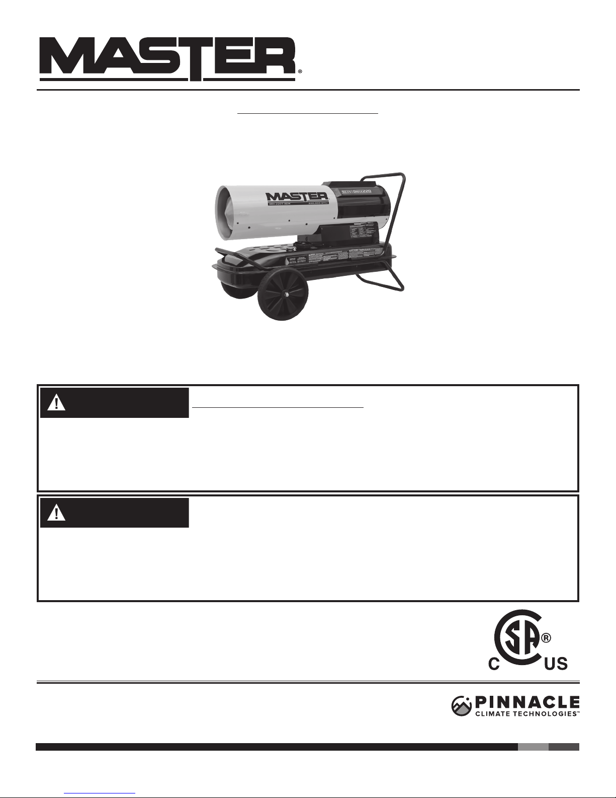
SilentDrive® FORCED AIR HEATER
User’s Manual &
Operating Instructions
MODEL NUMBERS:
MH-150T-SDR / MH-220T-SDR
CONSUMER: READ AND SAVE THESE INSTRUCTIONS
Locating Your Serial Number:
Your serial number can be found on a white label on the right side cover of your heater. For Example:
123456789. Have your Serial Number ready before calling customer service at 800-641-6996.
GENERAL HAZARD WARNING: READ AND UNDERSTAND ALL OF
THE INSTRUCTIONS IN THIS MANUAL BEFORE ASSEMBLING, START-
ING, OR SERVICING THE HEATER. Be sure to comply with the instructions and warnings provided
with this heater. Failure to comply can result in fire or explosion that can cause property loss, bodily
injury, or loss of life. Only persons who can follow and understand these instructions should operate
or service this heater. If you need heater info; such as an operating manual, labels, etcetera, contact
Pinnacle Climate Technologies at 800-641-6996.
NOT FOR USE IN RESIDENTIAL LIVING AREAS OR IN ENCLOSED
SPACES WITHOUT ADEQUATE VENTILATION. FOR OUTDOOR USE.
INDOOR USE PERMITTED ONLY FOR: THE TEMPORARY HEATING OF ADEQUATELY VENTILATED BUILDINGS OR STRUCTURES UNDER CONSTRUCTION,
ALTERATION OR REPAIR. This is an unvented portable heater that uses air (Oxygen) from within
the area in which it is used. Failure to provide adequate combustion and ventilation air will result in
asphyxiation, carbon monoxide poisoning, bodily injury or death. Refer to “Ventilation” on Page 7.
U.S. Patent No. 9,644,863
FACTORY ID: 001
Fax: 320-251-2922 • Web: www.masterindustrialproducts.com • Email: info@pinnacleclimate.com
1 Industrial Blvd #101, Sauk Rapids, MN 56379 USA • Toll Free (800) 641-6996
© 2018 Pinnacle Climate Technologies, Inc. MASB-407
Page 2
© 2018 Pinnacle Climate Technologies, Inc. Silent Drive Forced Air Heater User’s Manual
NEVER LEAVE HEATER UNATTENDED WHILE BURNING OR
WHILE CONNECTED TO A POWER SOURCE
WARNING
WARNING
WARNING
WARNING
WARNING
Safety Information.......................................................2-3
What’s in the Box.............................................................4
Specifications...................................................................4
Features..
Ventilation......................................................................
Operation......................................................................6-7
.........................................................................
TABLE OF CONTENTS
Maintenance.................................................................8-9
Wiring Diagram...............................................................10
Troubleshooting Guide.................................................11
Exploded View
5
Parts List.....................................................................12-13
..6
Limited Warranty............................................................14
.........................................................
.....12
SAFETY INFORMATION
FIRE, BURN, INHALATION AND EXPLOSION HAZARD. Keep com-
bustibles such as; building materials, paper or cardboard a safe dis-
tance away from the heater as recommended by these instructions.
Never use the heater in spaces which contain products such as; gasoline, solvents, paint
thinners, dust particles, volatile or airborne combustibles or any unknown chemicals. This is
an unvented portable heater. It uses air (Oxygen) from the area in which it is used. Adequate
combustion and ventilation air must be provided. Refer to “Ventilation” on page 6. Bulk fuel
storage should be a minimum of 25 feet from heater.
DO NOT OPERATE THIS HEATER UNTIL YOU HAVE READ AND
THOROUGHLY UNDERSTAND THESE SAFETY AND OPERATING
INSTRUCTIONS.
Failure to comply with the precautions and instructions provided with this heater can result in
death, serious bodily injury, property loss or damage from the hazards of fire, soot production,
explosions, burns, asphyxiation or carbon monoxide poisoning. Only persons who can read
and understand these instructions should use or service this heater
.
DO NOT START THE HEATER WHEN EXCESS OIL HAS ACCUMU-
LATED.
DO NOT START THE HEATER WHEN THE CHAMBER IS HOT.
This product contains chemicals, including lead, which are known to the
State of California to cause cancer and birth defects or other reproductive
harm. For more information go to www.P65Warnings.ca.gov.
MASSACHUSETTS RESIDENTS: Massachusetts state law prohibits the use of this heater in
any building which is used in whole or in part for human habitation. Use of this heating device
in Massachusetts requires local fire department permit (M.G.L.C. 148, Section 10A).
NEW YORK CITY RESIDENTS: The New York City Fire Code prohibits the storage, handling
and use of kerosene fueled heaters for space heating. Any person violating that provision may
be punished by a fine up to $10,000 and a term of imprisonment of up to 6 months.
THE INSTALLATION OF THIS HEATER SHALL COMPLY WITH THE REGULATIONS OF THE
AUTHORITIES HAVING JURISDICTION.
Look for this icon throughout the manual for helpful tips on how to assemble,
use and clean your SDR Heater.
2
Page 3
© 2018 Pinnacle Climate Technologies, Inc. Silent Drive Forced Air Heater User’s Manual
NEVER LEAVE HEATER UNATTENDED WHILE BURNING OR
WHILE CONNECTED TO A POWER SOURCE
WARNING
WARNING
WARNING
WARNING
DANGER
SAFETY INFORMATION CONT.
RISK OF INDOOR
AIR POLLUTION!
The products described in this manual are kerosene direct-fired, forced air heaters. Kerosene
forced air heaters are primarily intended for use
for temporary heating of buildings under construction, alteration or repair. Direct-fired means
that all of the combustion products of the heater
enter the heated space. This appliance is rated
at 98% combustion eciency, but does produce
small amounts of carbon monoxide.
Carbon monoxide is toxic. Humans can tolerate
only small amounts of carbon monoxide and so
precautions should be taken to provide proper
ventilation. Failure to provide proper ventilation
in accordance with the instructions in this manual
can result in death.
CARBON MONOXIDE POISONING MAY LEAD TO
DEATH!
People with breathing problems should consult a
physician before using this heater.
Early signs of carbon monoxide poisoning resemble the flu. Symptoms of improper ventilation
/ carbon monoxide poisoning are:
Headache • Dizziness • Nausea • Dry Mouth
Sore Throat • Burning of Nose and Eyes
If you experience any of these symptoms:
GET FRESH AIR AT ONCE! Have your heater
serviced and check for proper ventilation. Some
people are more aected by carbon monoxide
than others. These include: pregnant women,
those with heart or lung problems, anemia or
those under the influence of alcohol or at high
altitudes.
RISK OF ELECTRIC
SHOCK!
ALWAYS use only the electrical power (voltage and
frequency) specified on the model plate of the heater.
ALWAYS use only three-prong, grounded outlet and
extension cord.
ALWAYS use only 14 AWG or better extension cord.
ALWAYS unplug the heater when not in use.
ALWAYS install the heater so that it is not directly
exposed to water spray, rain, dripping water, or wind.
RISK OF BURNS,
FIRE AND EXPLOSION!
NEVER use fuels such as gasoline, benzene, paint
thinners or other oil compounds in this heater.
NEVER refill the heater’s fuel tank while the heater
is operating or still hot. This heater is EXTREMELY
HOT while in operation.
NEVER block air inlet (rear) or air outlet (front).
NEVER use duct work in front or rear of heater.
NEVER move or handle heater while still hot.
NEVER transport heater with fuel in tank.
NEVER use with an external fuel tank.
Keep all combustible materials away from this heater.
Minimum Clearance From Combustibles
150T-SDR 220T-SDR
Top 4 ft. (125 cm) 4 ft. (125 cm)
Sides 4 ft. (125 cm) 4 ft. (125 cm)
Front 8 ft. (250 cm) 8 ft. (250 cm)
ALWAYS locate heater on a stable and level surface.
Not For Indoor Use. Indoor use permitted only
for the temporary heating of buildings under
construction, alteration or repair!
Provide at least a three square foot (2,800 sq
cm) opening of outside air for every 100,000
Btu/Hr (29 kW) heater rating. Refer to “Ventilation” on page 6 for further instructions.
If your heater is equipped with a thermostat, once it
is plugged in, it can start at anytime in accordance
with the thermostat setting.
CAUTION! HOT
WHILE IN OP-
ERATION. DO
NOT TOUCH. KEEP CHILDREN, ANIMALS,
CLOTHING AND COMBUSTIBLES AWAY
FROM HEATER.
3
Page 4
© 2018 Pinnacle Climate Technologies, Inc. Silent Drive Forced Air Heater User’s Manual
NEVER LEAVE HEATER UNATTENDED WHILE BURNING OR
WHILE CONNECTED TO A POWER SOURCE
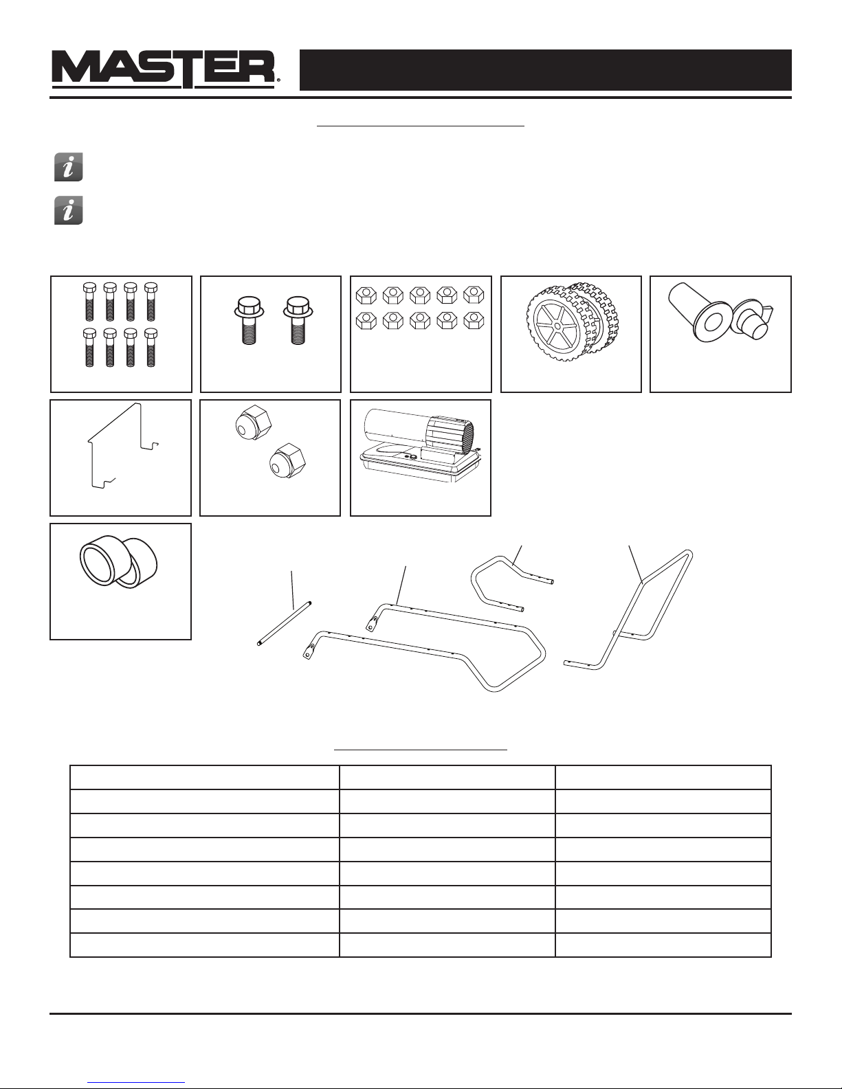
WHAT’S IN THE BOX
Tip: Be sure to remove the axle from the
side of the Styrofoam packaging.
Tip: Use a power screwdriver and locking
wrench for easier assembly.
50 mm Screws (8)
Safety Guard (1)
30 mm Screws (2)
Axle Nuts (2)
Axle
Wheel Support Frame
Tools Needed:
- Phillips head screw driver
- 8 mm open end wrench
- 19 mm open end wrench
8 mm Nuts (10)
Heater (1)
Front Handle
Tires (2)
Spare Drain Bolt (1)
Rear Handle
Spacers (2)
SPECIFICATIONS
Model # 150T-SDR 220T-SDR
Rating: Btu/Hr 150,000 220,000
Fuel Consumption: Gal/Hr / L/Hr 1.14 / 4.32 1.67 / 6.32
Fuel Tank Capacity: Gallons / Liters 10 / 37.9 13 / 49.2
Pump Pressure: PSI / BAR 111 / 7.65 123 / 8.48
Volts: AC/Hz 120VAC ~ 60 Hz 120VAC ~ 60 Hz
Amps ≤3.15A ≤3.15A
Phase 1Ø 1Ø
Specifications subject to change without notice.
4
Page 5
© 2018 Pinnacle Climate Technologies, Inc. Silent Drive Forced Air Heater User’s Manual
NEVER LEAVE HEATER UNATTENDED WHILE BURNING OR
WHILE CONNECTED TO A POWER SOURCE
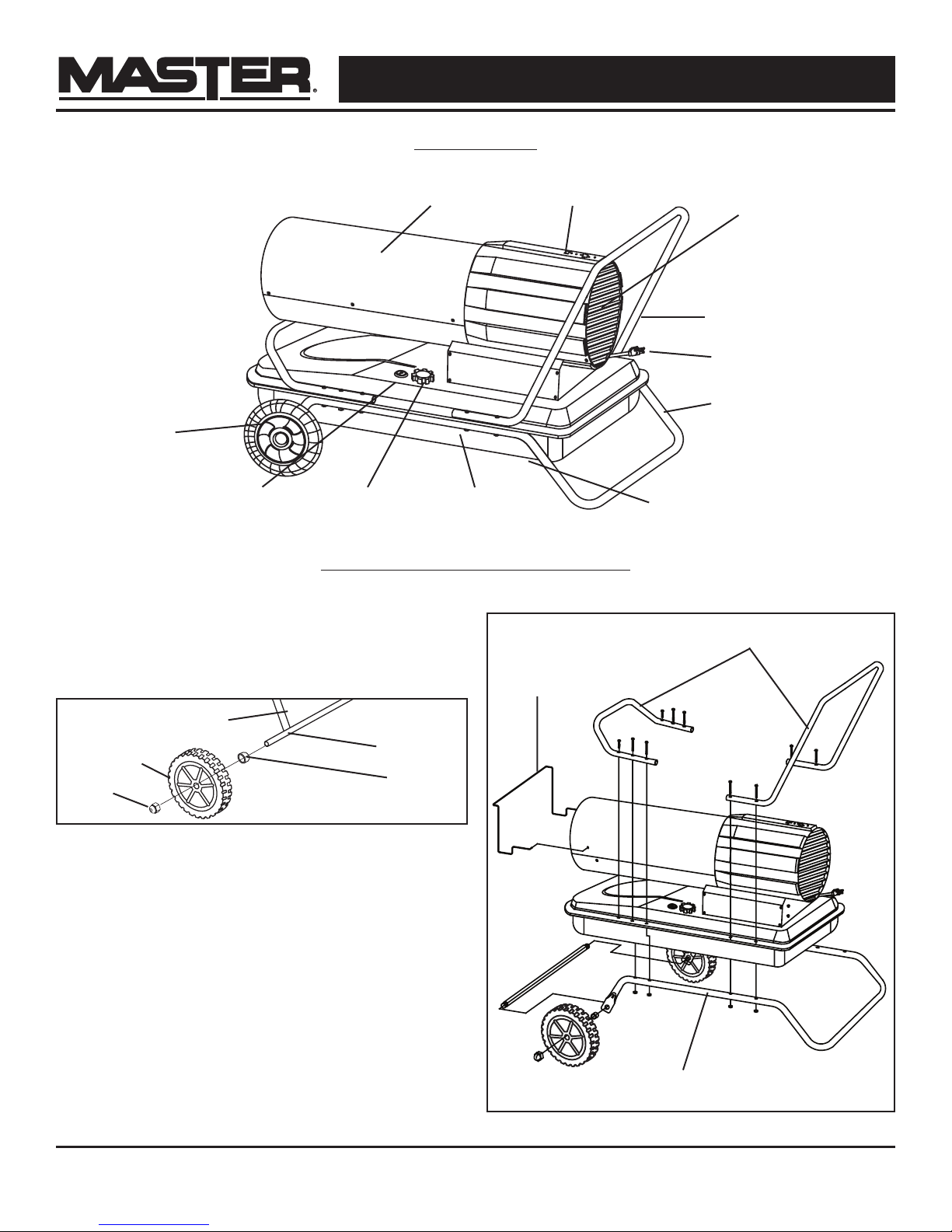
FEATURES
Wheel
Fuel Gauge Fuel Cap Fuel Tank Drain Bolt
ASSEMBLY INSTRUCTIONS
Models: 150T-SDR / 220T-SDR
1. Insert axle through holes in wheel support.
2. Slide then spacer onto axle.
3. Slide wheel onto axle and hold in place with the
axle nuts. (See Figure 1).
Wheel Support Frame
Tire
Axle Nut
Axle
Spacer
Control PanelShell
Safety Guard
Rear Guard
Handle
Power Cord
Support Frame
Handle
Figure 1
4. Place heater on wheel support frame and line up
holes on the fuel tank lip.
5. Attach front handle with (4) long screws
(50 mm) and (4) nuts through the second and
third hole from the front on both sides of the tank
lip and wheel support frame and tighten firmly.
6. Insert (2) short screws (30 mm) through the first
hole the front of in the tank lip and tighten firmly.
Make certain all (6) screws are secure.
7. Attach rear handle with (4) long screws (50 mm)
and (4) nuts through the first and second hole
from the rear on both sides of the tank lip and
wheel support frame and tighten firmly.
Figure 2
Wheel Support Frame
8. Attach front guard with the included hardware.
5
Page 6
© 2018 Pinnacle Climate Technologies, Inc. Silent Drive Forced Air Heater User’s Manual
NEVER LEAVE HEATER UNATTENDED WHILE BURNING OR
WHILE CONNECTED TO A POWER SOURCE
WARNING
DANGER
CAUTION
DANGER
- Risk of indoor air pollution and Carbon Monoxide Poisoning. Not For Indoor Use. Indoor use permitted
only for the temporary heating of buildings under construction, alteration or repair.
- Refer to Safety Information on page 3 for information about Carbon Monoxide Poisoning.
- ALWAYS provide a fresh air opening in the heated space of at least three square feet (2,800 sq. cm) for each 100,00
Btu/Hr. (29 kW) of heater output. Provide a larger opening if more heaters are being used.
VENTILATION
Minimum Ventilation Opening Needed
150T-SDR 220T-SDR
5.3 ft.² 6.5 ft.²
3760 cm² 5990 cm²
OPERATION
Fueling The Heater:
Kerosene (K-1)
For optimal performance of this heater, it is strongly suggested that K-1 kerosene be used. K-1 kerosene has been refined to virtually eliminate contaminants, such as sulfur, which can cause a rotten
egg odor during the operation of the heater. Using
diesel fuel can cause excess soot production. Do
not use Bio-Diesel as this fuel will damage your
heater’s seals and filter.
- CSA certified for use with K-1 kerosene,
no. 1 diesel, Jet A Fuel, no. 1 fuel oil.
DO NOT use any fuel that is not approved above.
- NEVER use fuel such as, benzene, alcohol, white glass,
camp stove fuel, paint thinners, farm diesel, or other oil
compounds in this heater. THESE ARE VOLATILE
FUELS THAT CAN CAUSE A FIRE OR EXPLOSION.
CARBON MONOXIDE POISONING MAY LEAD TO
DEATH!
NEVER REFUEL
THIS HEATER
WHILE IT IS HOT
OR OPERATING. FIRE OR EXPLOSION
COULD RESULT.
DO NOT USE GASOLINE OR CRANKCASE DRAININGS.
- NEVER store kerosene in the living space. Kerosene
should be stored in a well ventilated area outside
the living area.
- NEVER store kerosene in direct sunlight or near a
source of heat.
- NEVER use kerosene that has been stored from one
season to the next. Kerosene deteriorates over time.
OLD KEROSENE WILL NOT BURN PROPERLY IN
THIS HEATER.
NOTE: Kerosene should only be stored in a blue container that is clearly marked “Kerosene.” Never store
kerosene in a red container. Red is associated with
gasoline.
FILL THE TANK OUTDOORS. BE SURE THAT
THE HEATER IS ON LEVEL GROUND WHEN
FUELING, AND NEVER OVERFILL THE
TANK.
6
NEVER FILL THE
FUEL TANK INDOORS. ALWAYS
Page 7
© 2018 Pinnacle Climate Technologies, Inc. Silent Drive Forced Air Heater User’s Manual
NEVER LEAVE HEATER UNATTENDED WHILE BURNING OR
WHILE CONNECTED TO A POWER SOURCE
SDR 220 Rating Label + Control Panel
Model - Modelo MH-220T-SDR
COMPLIES WITH UL 733 AND
CSA-B140.0-03 AND CSA B140.8-1967
Minimum Distance From Combustibles:
Outlet: 8 ft. (250 cm) Sides / Top / Rear: 4 ft. (125 cm)
Minimas Distancias de Separacion de Materiales
Combustibles:
Salida de Aire: 8 ft. (250 cm)
Lateral / Superior / Posterior: 4 ft. (125 cm)
BTU/Hr - BTU/h 220,000
Fuel Consumption Gal./Hr.
Consumo de Combustible Gal./h
Fuel Tank Capacity Gal.
Capacidad del Depósito Gal.
V~Hz/Amps - V~Hz/Amperes 120V~60Hz / 3.15
Fuse - Fusible 3.15A
Type of Fuel No. 1 / Kerosene
Tipo de aceite combustible No. 1 / Queroseno
Maximum Air Outlet Temp. °F
Max. Temp. Del Aire De Salida °C
Pump Pressure PSI - Presión de le Bomba 123
Phase - Fase 1Ø
1.67
13
1025
552
© 2018 Pinnacle Climate Technologies, Inc.
www.masterindustrialproducts.com
Made In China
Hecho en China
See Operating Instructions and Troubleshooting on
side panel.
Las instrucciones de Funcionamiento y soluciónes
de problemas se encuentran en el panel lateral.
OPERATION CONT.
Starting the Heater: (Ignition)
1. Fill the tank with kerosene or other approved
fuel until needle on fuel gauge points to “F”.
2. Replace fuel cap and tighten firmly.
3. Connect the heater to a three prong
(grounded) power source. You must use a
three prong (grounded) extension cord that
is at least 6 feet long and is a minimum of 14
AWG rating.
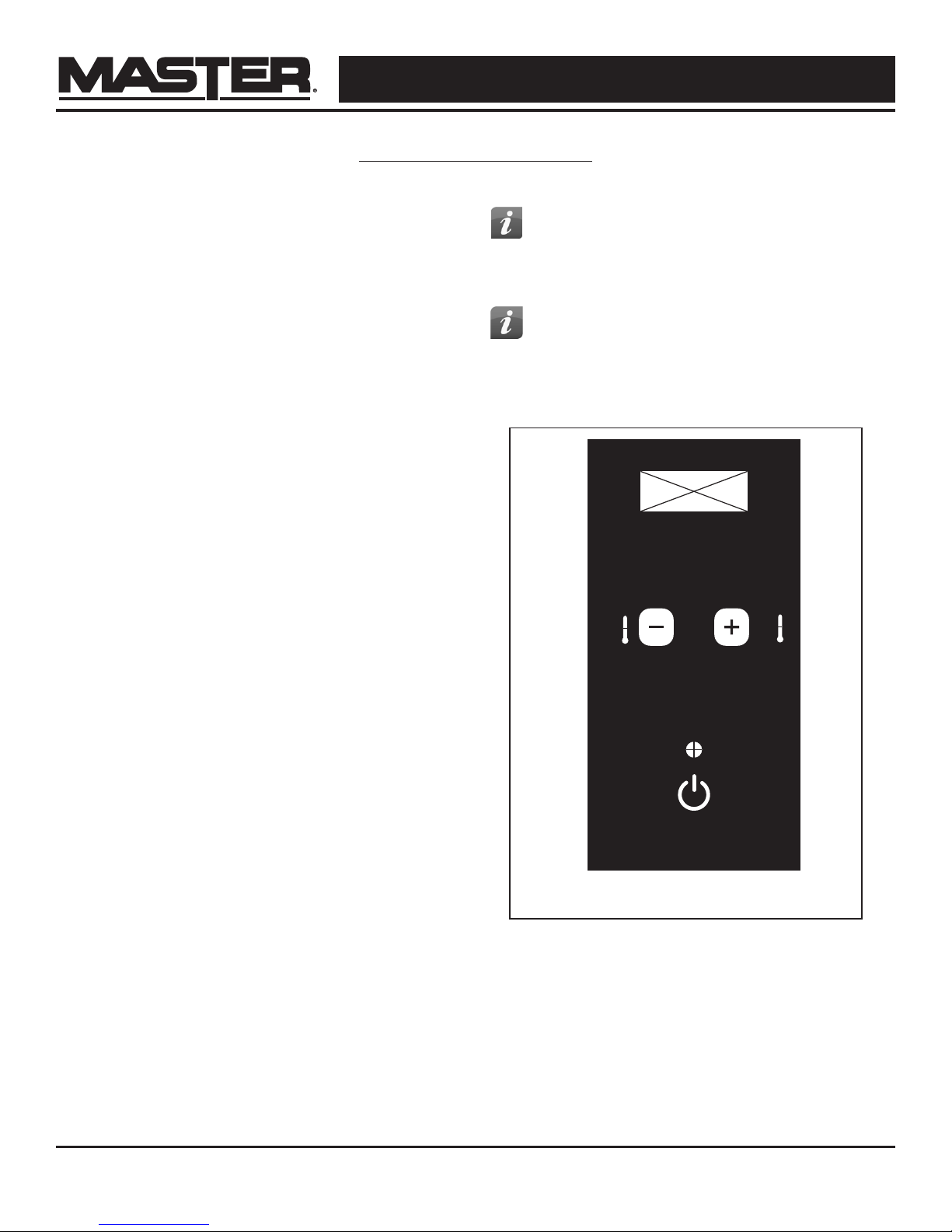
4. Press the power button to power on the
heater (see Figure 3).
5. Select desired temperature using temperature
+/- buttons.
6. The heater will ignite once the temperature
setting is higher than the ambient
temperature in the space.
Stopping / Restarting Heater:
- To stop the heater, move the power switch to
the “O” position and unplug the power cord.
- To restart the heater; wait 10 seconds and
follow ignition steps.
Adjusting the Pump Pressure:
TIP: If the heater does not ignite, the
thermostat may be set too low. Increase the
temperature to a higher setting until the heater
ignites.
TIP: If the heater does not ignite; press
power button to power o the heater, check
steps 1-3 above and press power button to
power ON the heater.
°F
°F
- Remove the right side cover (4 screws). Behind
the panel, the pump will have a brass screw.
Turn screw in quarter turn increments.
- Clockwise increases the pressure.
- Counterclockwise decreases pressure.
Figure 3
7
Page 8
© 2018 Pinnacle Climate Technologies, Inc. Silent Drive Forced Air Heater User’s Manual
NEVER LEAVE HEATER UNATTENDED WHILE BURNING OR
WHILE CONNECTED TO A POWER SOURCE
WARNING
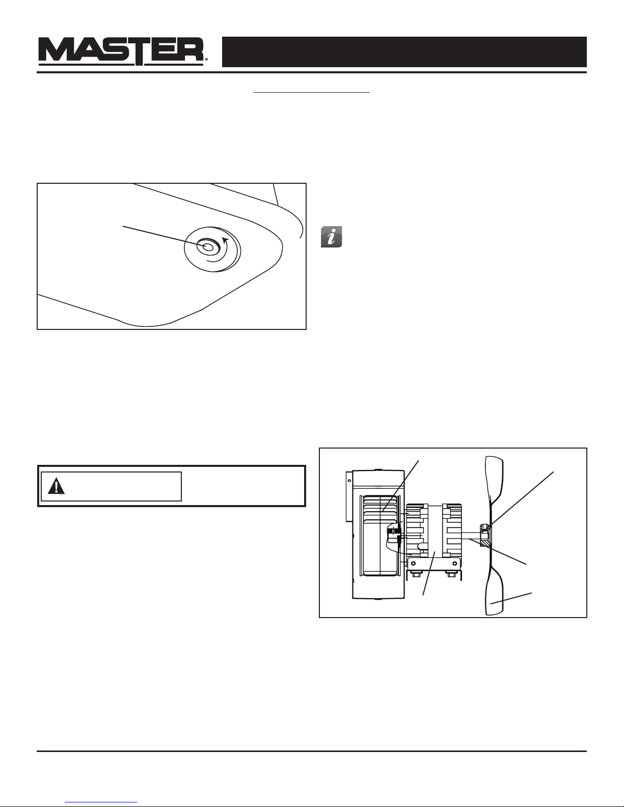
Long Term Storage:
1. Drain fuel through the drain bolt in the bottom of
the fuel tank.
2. To remove the drain bolt, unscrew
counterclockwise (see Figure 4).
MAINTENANCE
Service:
DO NOT TAMPER WITH THE UNIT. HAVE A
COMPETENT SERVICEMAN MAKE ANY NECESSARY
ADJUSTMENT OR REPAIRS.
Use only original equipment parts. The use of alternate
or third party components can cause unsafe operating
conditions and will void your warranty.
Drain Bolt
Figure 4
3. Using a small amount of kerosene, rinse and swirl
the kerosene inside of the fuel tank, empty the
tank fully.
4. To replace the drain bolt, insert the drain head fully
into the drain hole and screw clockwise.
IMPORTANT: Never store leftover kerosene between
seasons, using old fuel can damage heater.
Never service
heater while it is
plugged in or hot!
We suggest following a maintenance schedule as follows:
TIP: To order OEM parts call (800) 641-6996
FUEL / FUEL TANK:
Flush tank every 200 hours of operation or as needed.
DO NOT flush with water, use fresh K-1 kerosene only.
FAN BLADES:
Blades should be cleaned at least once per heating
season, depending on conditions. Remove all
accumulated dust and dirt with a damp cloth, taking
care not to bend any of the fan blades. Be sure the
blades are dry before re-starting the heater. For fan
assembly removal, see Figure 5.
Sirroco Fan
Set Screw
Motor Shaft
Fan Blade
Figure 5
Motor
8
Page 9
© 2018 Pinnacle Climate Technologies, Inc. Silent Drive Forced Air Heater User’s Manual
NEVER LEAVE HEATER UNATTENDED WHILE BURNING OR
WHILE CONNECTED TO A POWER SOURCE
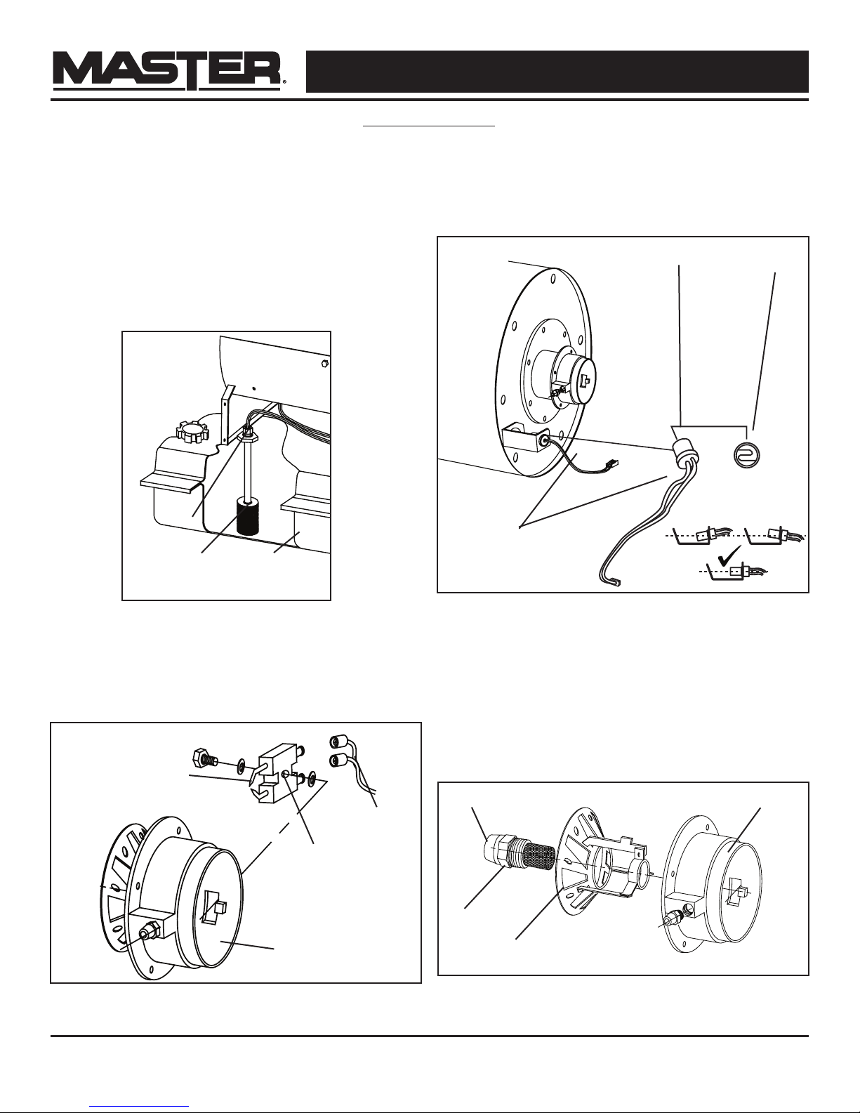
FUEL FILTER:
Maintenance
The fuel filter should be cleaned at least twice
per heating season. Clean the filter by rinsing
it in clean K-1 Kerosene. Contaminated fuel
could make cleaning the fuel filter necessary
immediately.
NOTE: To remove the filter from models turn filter
90º counter-clockwise. See Figure 6.
PHOTOCELL:
The photocell should be cleaned using a cotton
swab dipped in alcohol or water at least once per
heating season, or more depending on conditions.
See Figure 8.
Photocell
Photocell lens
Fuel Line
Fuel Filter
Figure 6
Fuel Tank
SPARK PLUG:
Clean and re-gap every 600 hours of operation, or
replace as needed. After removing the spark plug,
clean the terminals with a wire brush. Re-gap the
terminals to 0.140” (3.5mm) See Figure 7.
Gap (3.5 mm)
Ignitor Wire
Spark Plug
Photocell Wire
X
Figure 8
X
NOZZLES:
Nozzles should be cleaned or replaced at least
once per heating season. Contaminated fuel could
make this necessary immediately. To clean dirt
from nozzle, blow compressed air through nozzle
front. It may be necessary to soak the nozzle in K-1
kerosene to loosen any dirt particles. See Figure 9.
Nozzle Face
Nozzle
Burner Head
Burner Head
Figure 7
Dispenser
Figure 9
9
Page 10
© 2018 Pinnacle Climate Technologies, Inc. Silent Drive Forced Air Heater User’s Manual
NEVER LEAVE HEATER UNATTENDED WHILE BURNING OR
WHILE CONNECTED TO A POWER SOURCE
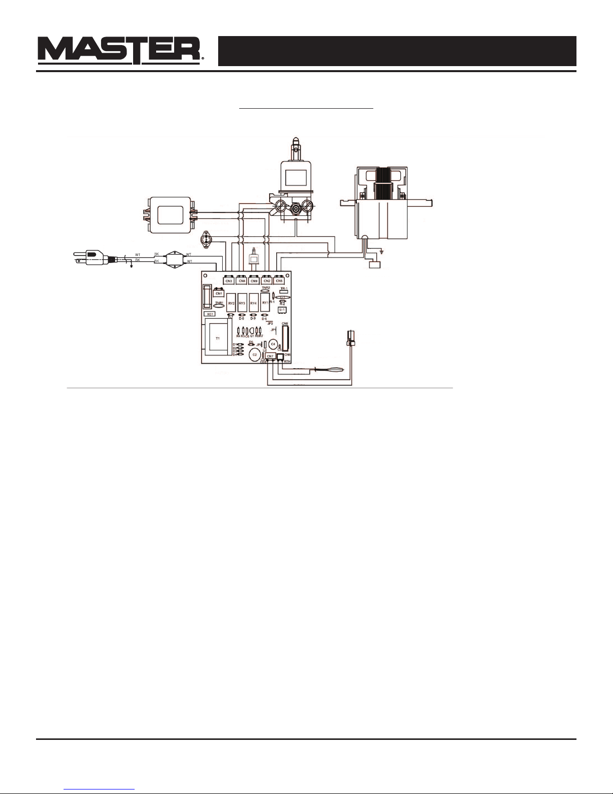
1
2
3
4
5
6
7
8
9
102613
11
12
12
BK
BK
BK
BK
AC 250V / 3.15A
BK
BL
GN
RD
BR
YL
BL
BL
BL
BL
RD
RD
1. Encendedor
2. Bomba del Combustible
3. Motor
4. Condensador
5. Control de Limite
6. El Vertedero
7. Asamblea de P.C.B.
8. Termistor
9. Fotocélula
10. P-Solenoide
11. La Energía
12. Tierra
13. Filtro de E.M.I.
WT. Blanco
BK. Negro
BL. Azul
YL. Amarillo
RD. Rojo
GN. Verde
BR. Marrón
GN
13
WIRING DIAGRAM
1. Igniter
2
RD
RD
BL
BL
1
5
GN
12
13
AC 250V / 3.15A
11
102613
7
BL
6
YL
BL
BR
RD
BK
BK
BK
BK
8
GN
BL
BK
4
9
3
12
2. Pump
3. Motor
4. Condensor
5. Limit Control
6. Dump
7. PCB Assembly
8. Thermistor
9. Photocell
10. P-Solenoid
11. Power
12. Earth
13. E.M.I. Filter
WT. White
BK. Black
BL. Blue
YL. Yellow
RD. Red
GN. Green
BR. Brown
10
Page 11

© 2018 Pinnacle Climate Technologies, Inc. Silent Drive Forced Air Heater User’s Manual
NEVER LEAVE HEATER UNATTENDED WHILE BURNING OR
WHILE CONNECTED TO A POWER SOURCE
Problem Possible Cause Solution
Heater Ignites, but main PCB shuts
o after a short period of time.
LED display shows “E1.”
TROUBLESHOOTING GUIDE
1. Dirty fuel filter.
2. Nozzle is dirty.
3. Photocell lens is dirty.
4. Photocell not installed properly.
5. Photocell is defective.
6. Improper electrical connection
between main PCB and photocell.
1. Clean / replace fuel filter.
2. Clean / replace Nozzle.
3. Clean / replace photocell.
4. Adjust photocell position
5. Replace photocell
6. Check wiring connections.
Heater will not operate or motor
runs for a short time.
LED display shows “E1.”
Fan does not operate when heater
is plugged in and power switch is
in the “ON” position. LED display
shows “E1” or “E2.”
Poor combustion and / or excess
soot production.
Heater does not turn on and the
lamp is not lit.
1. No kerosene in the fuel tank.
2. Corroded spark plug or incorrect
plug gap.
3. Dirty fuel filter.
4. Dirty nozzle.
5. Moisture in fuel tank.
6. Improper electrical connection
between transformer and circuit
board.
7. Ignitor wire not connected to spark
plug.
8. Defective ignitor.
1. Thermostat is set too low.
2. Broken electrical connection
between main PCB and motor.
1. Dirty fuel filter.
2. Poor quality of fuel.
3. PSI is too high or too low.
1. Temperature limit sensor has
overheated.
2. No electrical power.
3. Fuse is blown.
4. Improper electrical connection
between temperature limit sensor
and circuit board.
1. Fill tank with fresh kerosene.
2. Clean / replace spark plug.
3. Clean / replace fuel filter.
4. Clean / replace nozzle.
5. Rinse fuel tank with clean, fresh
kerosene.
6. Inspect all electrical connections.
7. Re-attach ignitor wire to spark plug.
8. Replace ignitor.
1. Rotate thermostat to a higher setting
2. Inspect all electrical connections.
1. Clean / replace fuel filter.
2. Flush fuel tank and refuel heater.
3. Use proper pressure.
1. Push power switch to “OFF and
allow heater to cool for 10 minutes.
Restart heater.
2. Check power cords for proper
connection and test the power
supply.
3. Check / replace the fuse.
4. Inspect all electrical connections.
11
Page 12
© 2018 Pinnacle Climate Technologies, Inc. Silent Drive Forced Air Heater User’s Manual
NEVER LEAVE HEATER UNATTENDED WHILE BURNING OR
WHILE CONNECTED TO A POWER SOURCE
39
EXPLODED VIEW
40
4
9
24
32
10
14
15
16
17
24
6
7
5
8
12
26
22
13
2
27
31
11
33
1
3
25
28
29
35
34
30
19
18
20
21
38
23
37
36
PARTS LIST
Item # Description 150T-SDR 220T-SDR
1 Combustion Chamber 70-011-1000 70-011-1010
2 Main Power PCB 70-027-2005 70-027-2005
3 Power PCB Case 70-027-1250 70-027-1250
4 PCB Lead Wire 70-027-1025 70-027-1025
5 Nozzle 70-015-1000 70-015-1010
6 Air Dispenser 70-063-1000 70-063-1000
7 Burner Head 70-014-1000 70-014-1000
8 Fuel Line Nipple 70-014-1100 70-014-1100
9 Spark Plug 70-052-1000 70-052-1000
10 Limit Control 70-019-1000 70-019-1000
12
Page 13
© 2018 Pinnacle Climate Technologies, Inc. Silent Drive Forced Air Heater User’s Manual
NEVER LEAVE HEATER UNATTENDED WHILE BURNING OR
WHILE CONNECTED TO A POWER SOURCE
Item # Description 150T-SDR 220T-SDR
11 Limit Control Bracket 70-019-1010 70-019-1010
12 Photocell 70-016-1000 70-016-1000
13 Photocell bracket 70-016-0101 70-016-0101
14 Air Draft Tube 70-300-0001 70-300-0001
15 Duct Bracket 70-300-0020 70-300-0020
16 Sirroco Fan 70-060-0001 70-060-0001
17 Duct Assembly 70-300-0100 70-300-0100
18 Motor Assembly 70-020-1000 70-020-1000
19 Motor Supporter 70-020-1010 70-020-1010
20 Blower Fan 70-024-1000 70-024-1000
21 Fan Guard 70-016-2000 70-016-2000
22 Ignitor 70-037-0350 70-037-0350
23 Side Cover 70-008-1100 70-008-1110
24 Power Cord 70-034-1000 70-034-1000
25 Return Fuel Line 70-036-0015 70-036-0015
26 Intake Fuel Line 70-036-1010 70-036-1010
27 Fuel Pump 70-400-0110 75-400-0110
28 Fuel Gauge 70-007-0215 70-007-0215
29 Fuel Cap 70-006-0140 70-006-0140
30 Fuel Filter 70-003-1000 70-003-1000
31 Drain Bolt 70-002-0115 70-002-0115
32 Rear Handle 70-043-1000 70-043-1100
33 Wheel Support Frame 70-041-1000 70-041-1100
34 Front Handle 70-043-1002 70-043-1102
35 Handle Bolts 70-043-1001 70-043-1001
36 Wheel 70-041-1400 70-041-1400
37 Wheel Axle 70-041-1510 70-041-1510
38 Wheel Nut 70-041-0550 70-041-0550
39 Safety Guard 70-065-1000 70-065-1000
40 Control Panel PCB 70-027-1005 70-027-1005
PARTS LIST
13
Page 14

© 2018 Pinnacle Climate Technologies, Inc. Silent Drive Forced Air Heater User’s Manual
NEVER LEAVE HEATER UNATTENDED WHILE BURNING OR
WHILE CONNECTED TO A POWER SOURCE
LIMITED WARRANTY
Pinnacle Climate Technologies, Inc. warrants this heater to
the original retail purchaser only, to be free from defects in
material and workmanship for a period of one (1) year from
the date of initial purchase. This product must be properly
installed, maintained and operated in accordance with the
instructions provided.
Pinnacle Climate Technologies, Inc. requires reasonable
proof of your date of purchase from an authorized retailer
or distributor. Therefore, you should keep your sales slip,
invoice or cancelled check from the original purchase.
This Limited Warranty shall be limited to the repair or
replacement of parts, which prove defective under normal
use and service within the warranty period, and which
Pinnacle Climate Technologies, Inc. shall determine at its
reasonable discretion.
This warranty does not apply to products purchased for
rental use.
This Limited Warranty does not cover any failures or
operating diculties due to normal wear and tear, accident,
abuse, misuse, alteration, misapplication, improper
installation or improper maintenance and service by you
or any third party. Failure to perform normal and routine
maintenance on the heater, shipping damage, damage
related to insects, birds or animals of any kind, and damage
due to weather conditions are also not covered. In addition,
the Limited Warranty does not cover damage to the finish,
such as scratches, dents, discoloration, rust or other
weather damage, after purchase.
All transportation costs for the return of damaged product
or parts will be the responsibility of the purchaser. Upon
receipt of damaged item, Pinnacle Climate Technologies,
Inc. will examine the item and determine if defective.
Pinnacle Climate Technologies, Inc. will repair or replace
and return the item, freight pre-paid.
If Pinnacle Climate Technologies, Inc. finds the item to
be in normal operating condition, or not defective the item
will be returned freight collect. This Limited Warranty is
in lieu of all other express warranties. Pinnacle Climate
Technologies, Inc. disclaims all warranties for products that
are purchased from sellers other than authorized dealers or
distributors.
AFTER THE PERIOD OF THE ONE (1) YEAR EXPRESS
WARRANTY EXPIRES, Pinnacle Climate Technologies,
Inc. DISCLAIMS ANY AND ALL IMPLIED WARRANTIES,
INCLUDING WITHOUT LIMITATION THE IMPLIED
WARRANTIES OF MERCHANTABILITY AND FITNESS
FOR A PARTICULAR APPLICATION. FURTHER, Pinnacle
Climate Technologies, Inc. SHALL HAVE NO LIABILITY
WHATSOEVER TO PURCHASER OR ANY THIRD PARTY
FOR ANY SPECIAL, INDIRECT, PUNITIVE INCIDENTAL,
OR CONSEQUENTIAL DAMAGES. Pinnacle Climate
Technologies, Inc. assumes no responsibility for any defects
caused by third parties. This Limited Warranty gives the
purchaser specific legal rights; a purchaser may have other
rights depending upon where he or she lives. Some states
do not allow the exclusion or limitation of special, incidental
or consequential damages, or limitations on how long a
warranty lasts, so the above exclusion and limitations may
not apply to you.
Pinnacle Climate Technologies, Inc. does not authorize any
person or company to assume for it any other obligation
or liability in connection with the sale, installation, use,
removal, return or replacement of its equipment, and no
such representations are binding on Pinnacle Climate
Technologies, Inc.
Always be sure to specify the model number and serial
number when making any claim with Pinnacle Climate
Technologies, Inc. For your convenience, use the space
provided below to list this information.
Locating Your Serial Number:
Your serial number can be found on a white label on the right side cover of your heater. It will be a
series of 9 digits. For Example: 123456789. Have your Serial Number ready before calling customer
service at 800-641-6996.
Model #:________________________________
Serial #:________________________________
Date of Purchase: ________________________
14
Page 15

DANGER
DANGER
CHAUFFERETTE À AIR FORCÉ
SilentDrive
Manuel de l’utilisateur et
mode d’emploi
®
NUMÉROS DE MODÈLES:
MH-150T-SDR/MH-220T-SDR
NOTE AU CLIENT: LIRE ET CONSERVER CE MANUEL POUR CONSULTATION ULTÉRIEURE
Repérage du numéro de série:
Le numéro de série se trouve sur une étiquette blanche apposée du côté droit de la chauerette. Par exemple: 123456789.
Noter le numéro de série avant de contacter le service à la clientèle au 800-641-6996.
AVERTISSEMENT GÉNÉRAL DE DANGER: LIRE ET COMPRENDRE TOUTES LES
INSTRUCTIONS DE CE MANUEL AVANT D’ASSEMBLER, DE METTRE EN MARCHE
OU D’EFFECTUER DES RÉPARATIONS SUR CETTE CHAUFFERETTE. Toujours se
conformer aux instructions et aux avertissements fournis avec la chauerette. Le non-respect de ces directives pourrait
entraîner des risques d’incendie ou d’explosion pouvant causer de graves dommages à la propriété, des blessures ou
même la mort. Seules les personnes pouvant suivre et comprendre ces instructions devraient utiliser ou entretenir cette
chauerette. Pour obtenir plus de renseignements (manuel d’utilisation, étiquettes, etc.), contacter Pinnacle Climate
Technologies au 800-641-6996.
NE PAS UTILISER DANS DES ZONES RÉSIDENTIELLES OU DANS DES ESPACES
CLOS SANS VENTILATION ADÉQUATE. POUR USAGE EXTÉRIEUR. USAGE
INTÉRIEUR PERMIS SEULEMENT POUR : LE CHAUFFAGE TEMPORAIRE DES
STRUCTURES OU DES BÂTIMENTS BIEN VENTILÉS EN COURS DE CONSTRUCTION, DE MODIFICATION OU
DE RÉPARATION! Ceci est une chauerette portative non raccordée utilisant l’air (oxygène) ambiant de l’espace où
elle est utilisée. Une insusance d’air pour la combustion et la ventilation causera l’asphyxie, l’intoxication par oxyde de
carbone, des lésions corporelles ou la mort. Voir la section «Ventilation» à la page 7.
Nº de brevet U.S. 9,644,863
ID USINE : 001
Télécopieur : 320 251-2922 • Web : www.masterindustrialproducts.com • Courriel : info@pinnacleclimate.com
1 Industrial Blvd #101, Sauk Rapids, MN 56379 USA • Numéro sans frais 800-641-6996
© 2018, Pinnacle Climate Technologies, Inc.
Page 16

© 2018, Pinnacle Climate Technologies, Inc. Manuel de l’utilisateur de la chaufferette à air forcé à
entraînement silencieux
NE JAMAIS LAISSER UNE CHAUFFERETTE SANS
SURVEILLANCE LORSQU’ELLE BRÛLE OU QU’ELLE EST
BRANCHÉE À UNE SOURCE D’ALIMENTATION.
AVERTISSEMENT
AVERTISSEMENT
AVERTISSEMENT
AVERTISSEMENT
AVERTISSEMENT
TABLE DES MATIÈRES
Consignes de sécurité ..............................................2-3
Contenu de la boîte
Spécifications
Caractéristiques
Ventilation
Mode d’emploi
................................................................. 4
....................................................................... 6
...................................................... 4
............................................................. 5
............................................................6-7
Entretien
Schémas de câblage
Guide de dépannage
Vue éclatée
Liste des pièces
Garantie limitée
...................................................................... 8-9
...................................................10
...................................................11
.................................................................... 12
.......................................................12-13
.............................................................14
CONSIGNES DE SÉCURITÉ
RISQUE D’INCENDIE, DE BRÛLURE, D’INHALATION ET
D’EXPLOSION. Garder les matériaux combustibles tels que
matériaux de construction, papier ou carton à une distance
sécuritaire de la chauerette, selon les recommandations de ces instructions. Ne jamais utiliser la chauerette
dans des endroits qui contiennent des produits comme : essence, solvants, diluants à peinture, poussières,
substances combustibles volatiles ou aéroportées ou tout produit chimique de nature inconnue. Ceci est une
chauerette portative non raccordée, Elle utilise l’air (oxygène) ambiant de l’espace où elle est utilisée. Une
quantité d’air susante pour la combustion et la ventilation doit être fournie. Voir «Ventilation» à la page 6. Tout
stockage de carburant en vrac doit se trouver à un minimum de 7,6 mètres de la chauerette.
NE PAS UTILISER CETTE CHAUFFERETTE AVANT D’AVOIR LU
ET PARFAITEMENT COMPRIS CES CONSIGNES DE SÉCURITÉ
ET D’UTILISATION.
Le non-respect des précautions et instructions fournies avec cette chauerette peut entraîner la mort, des blessures
corporelles graves, des pertes ou dommages matériels dus aux risques d’incendie, à la production de suies, à des
explosions, à des brûlures, à l’asphyxie ou à un empoisonnement au monoxyde de carbone. Seules les personnes
qui peuvent lire et comprendre les présentes directives doivent utiliser ou faire l’entretien de cette chauerette.
NE PAS METTRE EN MARCHE LA CHAUFFERETTE LORSQU’IL
Y A ACCUMULATION D’HUILE.
NE PAS METTRE EN MARCHE LA CHAUFFERETTE LORSQUE
LA CHAMBRE DE COMBUSTION EST CHAUDE.
Ce produit contient des produits chimiques, dont du plomb, connus dans
l’État de Californie comme cancérigènes et causant des malformations
congénitales ou d’autres troubles de la reproduction. Pour de plus amples
informations, consulter www.P65Warnings.ca.gov.
RÉSIDENTS DU MASSACHUSETTS: Ce produit contient des produits chimiques, dont du plomb, connus dans
l’État du Massachusetts comme cause de malformations congénitales ou d’autres troubles de la reproduction.
L’utilisation de cet appareil de chauage au Massachusetts exige un permis du service d’incendie local
(M.G.L.C. 148, Section 10A).
RÉSIDENTS DE LA VILLE DE NEW YORK : Le Code de prévention des incendies de la ville de New York
interdit l’entreposage, la manipulation et l’utilisation de chauerette au kérosène pour le chauage localisé.
Toute personne contrevenant à cette disposition peut encourir une amende allant jusqu’à 10000dollars et
une peine d’emprisonnement allant jusqu’à 6mois.
L’INSTALLATION DE CETTE CHAUFFERETTE DOIT RESPECTER LA RÉGLEMENTATION DES AUTORITÉS
AYANT JURIDICTION.
Rechercher cette icône dans le manuel pour des conseils utiles sur la façon d’assembler,
d’utiliser et de nettoyer la chauerette SDR.
2
Page 17

© 2018, Pinnacle Climate Technologies, Inc. Manuel de l’utilisateur de la chaufferette à air forcé à
entraînement silencieux
NE JAMAIS LAISSER UNE CHAUFFERETTE SANS
SURVEILLANCE LORSQU’ELLE BRÛLE OU QU’ELLE EST
BRANCHÉE À UNE SOURCE D’ALIMENTATION.
AVERTISSEMENT
AVERTISSEMENT
AVERTISSEMENT
AVERTISSEMENT
DANGER
CONSIGNES DE SÉCURITÉ SUITE
RISQUE DE POLLUTION DE L’AIR INTÉRIEUR!
Les produits décrits dans ce manuel sont des chauerettes
à feu direct et à air pulsé alimentées au kérosène. Les
chauerettes à air forcé au kérosène sont principalement
destinées au chauage temporaire des bâtiments en cours
de construction, de modification ou de rénovation. Feu
direct signifie que tous les produits de combustion de la
chauerette entrent dans l’espace chaué. Cet appareil
est évalué à 98% de rendement de la combustion, mais il
produit de petites quantités de monoxyde de carbone.
Le monoxyde de carbone est toxique. Les êtres humains
peuvent en tolérer seulement de petites quantités; des
précautions doivent donc être prises pour assurer une
ventilation adéquate. Une ventilation non adéquate, en
violation des consignes figurant dans ce manuel, peut
entraîner la mort.
L’EMPOISONNEMENT
AU MONOXYDE DE
CARBONE PEUT
ENTRAÎNER LA MORT!
Les personnes atteintes de problèmes respiratoires doivent
consulter un médecin avant d’utiliser cet appareil.
Les premiers signes d’intoxication au monoxyde de carbone
ressemblent aux symptômes de la grippe. Ces symptômes
d’une mauvaise ventilation ou d’un empoisonnement au
monoxyde de carbone sont:
Mal de tête • Étourdissement • Nausée • Bouche sèche
Mal de gorge • Nez et yeux qui brûlent
Si un ou plusieurs de ces symptômes apparaissent :
SORTIR IMMÉDIATEMENT RESPIRER DE L’AIR FRAIS!
Faire vérifier ou réparer la chauerette et vérifier que la
ventilation est adéquate. Certaines personnes sont plus
aectées que d’autres par le monoxyde de carbone.
Celles-ci incluent: les femmes enceintes, les personnes
ayant des problèmes cardiaques ou pulmonaires, sourant
d’anémie ou qui se trouvent sous l’influence de l’alcool ou à
haute altitude.
Ne pas utiliser à l’intérieur. chauage temporaire des
structures ou des bâtiments bien ventilés en cours de
construction, de modification ou de réparation.
Fournir une ouverture d’au moins 2800cm sur l’air
extérieur pour chaque 100000 BTU/h (29 kWh) du régime
nominal de la chauerette. Voir la section «Ventilation» à
la page 6 pour plus de détails.
RISQUE DE DÉCHARGE ÉLECTRIQUE!
TOUJOURS utiliser uniquement l’alimentation électrique
(tension et fréquence) indiquée sur la plaque signalétique de
la chaufferette.
TOUJOURS utiliser seulement des prises ou des rallonges à
trois broches et avec mise à la terre.
TOUJOURS utiliser une rallonge de calibre 14 AWG ou plus.
TOUJOURS débrancher la chaufferette lorsqu’elle n’est
pasutilisée.
TOUJOURS installer la chaufferette de façon à ne pas
l’exposer directement aux brumes d’eau, à la pluie, à l’eau
de ruissellement ou au vent.
RISQUES DE BRÛLURES, D’INCENDIE ET D’EXPLOSION!
NE JAMAIS utiliser des combustibles comme de l’essence,
du benzène, des diluants à peinture ou d’autres composés
pétroliers dans cette chaufferette.
NE JAMAIS remplir le réservoir de carburant de cette chaufferette
alors qu’elle est en marche ou encore chaude. Cette chaufferette
est EXTRÊMEMENT CHAUDE lorsqu’elle est en marche.
NE JAMAIS bloquer l’entrée d’air (à l’arrière) ou la sortie d’air
(à l’avant).
NE JAMAIS utiliser de gaines ou de conduits d’air à l’avant
ou à l’arrière de l’appareil.
NE JAMAIS déplacer ou manipuler cette chaufferette
lorsqu’elle est encore chaude.
NE JAMAIS transporter cette chaufferette lorsqu’il y a du
carburant dans le réservoir.
NE JAMAIS l’utiliser avec un réservoir de carburant externe.
Garder tous les matériaux combustibles à l’écart de
cettechaufferette.
Dégagement minimal par rapport aux combustibles
150T-SDR 220T-SDR
Haut 125 cm 125 cm
Côtés 125 cm 125 cm
Avant 250 cm 250 cm
TOUJOURS placer sur une surface stable et plane.
Si la chaufferette est équipée d’un thermostat, une fois
branchée, elle peut se mettre en marche à tout moment
selon le réglage du thermostat.
MISE EN GARDE! CHAUD DURANT L’UTILISATION.
NE PAS TOUCHER. GARDER HORS DE LA PORTÉE
DES ENFANTS ET DES ANIMAUX ET À L’ÉCART DES
VÊTEMENTS OU DE TOUT MATÉRIAU COMBUSTIBLE.
3
Page 18

© 2018, Pinnacle Climate Technologies, Inc. Manuel de l’utilisateur de la chaufferette à air forcé à
entraînement silencieux
NE JAMAIS LAISSER UNE CHAUFFERETTE SANS
SURVEILLANCE LORSQU’ELLE BRÛLE OU QU’ELLE EST
BRANCHÉE À UNE SOURCE D’ALIMENTATION.
CONTENU DE LA BOÎTE
CONSEIL : Retirer l’essieu par le côté de
l’emballage de polystyrène.
CONSEIL : Pour un assemblage plus facile, utiliser
un tournevis électrique et une clé à cliquet.
Vis de 50 mm (8)
Protection de sécurité (1)
Vis de 30 mm (2)
Écrous d’essieu (2)
Essieu
Outils nécessaires :
- Tournevis cruciforme
- Clé à fourche de 8 mm
- Clé à fourche de 19 mm
Écrous de 8 mm (10)
Chauerette (1)
Châssis de roues
Poignée avant
Pneus (2)
Boulon de vidange de
rechange (1)
Poignée arrière
Bagues d’espacement (2)
SPÉCIFICATIONS
Modèles n° 150T-SDR 220T-SDR
Classement (Btu/h/kWh) 150000/44 220000/64,5
Consommation de carburant(L/h) 4,3 6,3
Capacité du réservoir (L) 37,9 49,2
Pression de la pompe (PSI/kPa) 111/765 123/848
Volts c.a./Hz
Ampères
Phase
Spécifications sujettes à modification sans préavis.
120 Vca/60 Hz 120 Vca/60 Hz
≤ 3,15 A ≤ 3,15 A
1Ø 1Ø
4
Page 19

© 2018, Pinnacle Climate Technologies, Inc. Manuel de l’utilisateur de la chaufferette à air forcé à
entraînement silencieux
NE JAMAIS LAISSER UNE CHAUFFERETTE SANS
SURVEILLANCE LORSQU’ELLE BRÛLE OU QU’ELLE EST
BRANCHÉE À UNE SOURCE D’ALIMENTATION.
CARACTÉRISTIQUES
Roulette
Jauge de carburant Bouchon du
réservoir de
Réservoir de
carburant
carburant
DIRECTIVES D’ASSEMBLAGE
Modèles : 150T-SDR/220T-SDR
1. Insérer l’essieu dans les trous du support pour les roues.
2. Placer ensuite la bague d’espacement sur l’essieu.
3. Placer la roue sur l’essieu et maintenir en place à l’aide
des écrous d’essieu. (Voir la Figure 1).
Châssis de roues
Essieu
Bague
d’espacement
Écrou
d’essieu
Pneu
Figure 1
Commande panneauEnveloppe
Protection de sécurité
Protecteur arrière
Poignée
Cordon électrique
Châssis de support
Bouchon de vidange
Poignée
4. Placer la chaufferette sur le châssis et aligner les trous
sur le rebord du réservoir de carburant.
5. Attacher la poignée avant à l’aide de (4) longs boulons
de 50 mm et de (4) écrous passant par le deuxième et
troisième trou de chaque côté du rebord du réservoir et
de l’armature du support et serrer fermement.
6. Insérer (2) boulons courts de 30 mm dans le premier
trou à l’avant du rebord du réservoir et serrer fermement.
S’assurer que tous les (6) boulons sont bien serrés en
place.
7. Attacher la poignée arrière à l’aide de (4) longs boulons
de 50 mm et de (4) écrous passant par le premier et
deuxième trou par l’arrière de chaque côté du rebord du
réservoir et du châssis et serrer fermement.
8. Fixer la protection avant avec la visserie incluse.
Figure 2
5
Châssis de roues
Page 20

© 2018, Pinnacle Climate Technologies, Inc. Manuel de l’utilisateur de la chaufferette à air forcé à
entraînement silencieux
NE JAMAIS LAISSER UNE CHAUFFERETTE SANS
SURVEILLANCE LORSQU’ELLE BRÛLE OU QU’ELLE EST
BRANCHÉE À UNE SOURCE D’ALIMENTATION.
AVERTISSEMENT
DANGER
ATTENTION
DANGER
VENTILATION
- Risque de pollution de l’air intérieur et d’empoisonnement au monoxyde de carbone. Ne pas utiliser à l’intérieur. L’usage à l’intérieur
n’est autorisé que pour le chauffage temporaire des bâtiments en cours de construction, de modification ou de réparation.
- Se reporter aux instructions de sécurité à la page 3 en ce qui concerne l’empoisonnement au monoxyde de carbone.
- TOUJOURS fournir une ouverture sur de l’air frais d’au moins 2800cm² pour chaque sortie de 100 000BTU/h (29 kWh) de capacité
nominale. Prévoir une ouverture plus importante si plusieurs chaufferettes sont utilisées.
Ouverture minimum requise pour la ventilation
150T-SDR 220T-SDR
5,3 pi² 6,5 pi²
3760 cm² 5990 cm²
MODE D’EMPLOI
Remplissage du réservoir de carburant :
Kérosène (K-1)
Pour obtenir une performance optimale, il est fortement
recommandé d’utiliser du kérosène K-1. Le kérosène K-1 a été
rané pour éliminer pratiquement tout contaminant comme,
par exemple, le soure qui peut occasionner une odeur
d’œufs pourris durant l’utilisation. L’utilisation de carburant
diesel peut causer une production excessive de suie. Ne pas
utiliser de biodiésel, car ce carburant endommagera les joints
d’étanchéité et les filtres de la chauerette.
- Certifié CSA pour utilisation avec kérosène K-1, diesel
nº1, carburant Jet A, mazout nº 1.
N’utiliser aucun carburant qui n’est pas approuvé ci-dessus
- NE JAMAIS utiliser des carburants comme de l’essence, du
benzène, de l’alcool, de l’essence sans plomb, du combustible
pour réchaud de camping, du carburant agricole, des diluants à
peinture ou d’autres composés d’huile dans cette chaufferette.
CES COMBUSTIBLES VOLATILES PEUVENT PROVOQUER UN
INCENDIE OU UNE EXPLOSION.
- NE JAMAIS entreposer du kérosène dans un espace habitable.
Entreposer le kérosène dans un endroit bien ventilé, en dehors
d’un espace habitable.
- NE JAMAIS entreposer du kérosène sous les rayons directs du
soleil ou à proximité d’une source de chaleur.
- NE JAMAIS utiliser du kérosène entreposé la saison précédente
pour la saison suivante. Le kérosène se détériore avec le temps.
LE VIEUX KÉROSÈNE NE BRÛLE PAS CORRECTEMENT DANS
CETTE CHAUFFERETTE.
REMARQUE: Le kérosène doit uniquement être conservé dans
un contenant bleu clairement libellé «Kérosène». Ne jamais
entreposer du kérosène dans un conteneur rouge. Le rouge est
associé à l’essence.
L’EMPOISONNEMENT
AU MONOXYDE DE
CARBONE PEUT
ENTRAÎNER LA MORT!
NE JAMAIS REMPLIR
LE RÉSERVOIR SI
LA CHAUFFERETTE
EST CHAUDE OU EN MARCHE. CELA POURRAIT
DÉCLENCHER UN INCENDIE OU UNE EXPLOSION.
NE PAS UTILISER D’ESSENCE NI DE PRODUIT DE
RINÇAGE DE CARTERS D’HUILE.
NE JAMAIS
REMPLIR LE
RÉSERVOIR
À L’INTÉRIEUR. TOUJOURS REMPLIR LE
RÉSERVOIR À L’EXTÉRIEUR. S’ASSURER QUE LA
CHAUFFERETTE EST SUR UN SOL DE NIVEAU
LORS DU REMPLISSAGE DU RÉSERVOIR DE
CARBURANT ET NE JAMAIS FAIRE DÉBORDER LE
RÉSERVOIR.
6
Page 21

© 2018, Pinnacle Climate Technologies, Inc. Manuel de l’utilisateur de la chaufferette à air forcé à
entraînement silencieux
NE JAMAIS LAISSER UNE CHAUFFERETTE SANS
SURVEILLANCE LORSQU’ELLE BRÛLE OU QU’ELLE EST
BRANCHÉE À UNE SOURCE D’ALIMENTATION.
SDR 220 Rating Label + Control Panel
Model - Modelo MH-220T-SDR
COMPLIES WITH UL 733 AND
ANSIA 10.10-1998
CAN/CSA-B140.0-03 AND CSA B140.8-1967
Minimum Distance From Combustibles:
Outlet: 8 ft. (250 cm) Sides / Top / Rear: 4 ft. (125 cm)
Minimas Distancias de Separacion de Materiales
Combustibles:
Salida de Aire: 8 ft. (250 cm)
Lateral / Superior / Posterior: 4 ft. (125 cm)
BTU/Hr - BTU/h 220,000
Fuel Consumption Gal./Hr.
Consumo de Combustible Gal./h
Fuel Tank Capacity Gal.
Capacidad del Depósito Gal.
V~Hz/Amps - V~Hz/Amperes 120V~60Hz / 3.15
Fuse - Fusible 3.15A
Type of Fuel No. 1 / Kerosene
Tipo de aceite combustible No. 1 / Queroseno
Maximum Air Outlet Temp. °F
Max. Temp. Del Aire De Salida °C
Pump Pressure PSI - Presión de le Bomba 93
Phase - Fase 1Ø
1.67
13
1025
552
© 2018 Pinnacle Climate Technologies, Inc.
www.masterindustrialproducts.com
Made In China
Hecho en China
See Operating Instructions and Troubleshooting on
side panel.
Las instrucciones de Funcionamiento y soluciónes
de problemas se encuentran en el panel lateral.
MODE D’EMPLOI SUITE
Démarrage de la chauerette : (Allumage)
1. Remplir le réservoir de kérosène ou d’un autre
carburant approuvé jusqu’à ce que la jauge indique
« F ».
2. Replacer le bouchon et serrer fermement
3. Brancher la chaufferette dans une prise à trois broches
avec mise à la terre. Utiliser une rallonge d’une
longueur d’au moins 1,8 m dont le calibre est d’au
moins 14 AWG.
4. Appuyer sur le bouton de mise en marche de l’appareil
(voir la Figure 3).
5. Sélectionner la température désirée en utilisant les
boutons +/- de température.
6. L’appareil va s’allumer une fois que le réglage de la
température est plus élevé que la température ambiante
des lieux.
Arrêt/Remise en marche de la chauerette :
- Pour arrêter l’appareil, placer l’interrupteur sur arrêt (« O »)
et débrancher le cordon d’alimentation.
- Pour remettre l’appareil en marche, attendre 10
secondes, puis suivre les instructions de mise en
marche.
Réglage de la pression de la pompe :
- Retirer le capot de droite (4 vis). Une vis en laiton se
trouve sur la pompe derrière le panneau. Tourner la vis
en incréments d’un quart de tour.
- Vers la droite pour augmenter la pression.
- Vers la gauche pour diminuer la pression.
CONSEIL : Si l’appareil ne s’allume pas, il se peut
que le thermostat soit réglé à une température trop
basse. Augmenter la température jusqu’à ce que
l’appareil se mette en marche.
CONSEIL : Si l’appareil ne s’allume pas, appuyer
sur le bouton de mise en marche afin d’éteindre
l’appareil, vérifier les étapes 1 à 3 ci-dessus et
appuyer sur le bouton de mise en marche pour mettre
l’appareil sous tension.
°F
°F
Figure 3
7
Page 22

© 2018, Pinnacle Climate Technologies, Inc. Manuel de l’utilisateur de la chaufferette à air forcé à
entraînement silencieux
NE JAMAIS LAISSER UNE CHAUFFERETTE SANS
SURVEILLANCE LORSQU’ELLE BRÛLE OU QU’ELLE EST
BRANCHÉE À UNE SOURCE D’ALIMENTATION.
AVERTISSEMENT
Entreposage de longue durée :
1. Vidanger le réservoir de carburant au moyen du boulon
de vidange situé au bas du réservoir de carburant.
2. Pour enlever le boulon de vidange, le dévisser vers la
gauche (voir la Figure 4).
Bouchon de vidange
ENTRETIEN
Réparation :
NE PAS MODIFIER L’APPAREIL. TOUT AJUSTEMENT OU
RÉPARATION DOIT ÊTRE EFFECTUÉ PAR UN TECHNICIEN
COMPÉTENT.
Utiliser seulement des pièces de rechange d’origine.
L’utilisation de composants tiers ou de substitution risque
de créer des conditions de fonctionnement dangereuses et
annulera la garantie.
Il est recommandé de suivre le programme d’entretien suivant :
CONSEIL : Pour commander des pièces d’origine,
appeler au 800-641-6996
CARBURANT/RÉSERVOIR DE CARBURANT :
Rincer toutes les 200 heures de fonctionnement ou suivant
le besoin. NE PAS utiliser d’eau pour le rinçage, utiliser
uniquement du kérosène 1-K récent.
Figure 4
3. En utilisant une petite quantité de kérosène, agiter puis
rincer l’intérieur du réservoir. Vider complètement le
réservoir.
4. Pour remettre le boulon de vidange, insérer
complètement la tête du boulon et visser vers la droite.
IMPORTANT : Ne jamais entreposer le kérosène inutilisé
pendant l’été. L’utilisation de vieux carburant peut
endommager la chauerette.
Ne jamais faire l’entretien de la chauerette alors
qu’elle est branchée ou chaude!
PALES DE VENTILATEUR :
Les pales doivent être nettoyées au moins une fois par
saison de chauage, ou plus fréquemment selon l’état.
Éliminer l’accumulation de poussière et de saletés avec un
chion humide, en faisant attention de ne pas tordre les
pales. S’assurer que les pales de ventilateur sont sèches
avant de redémarrer la chauerette. Pour le démontage de
l’ensemble de ventilateur, voir la Figure 5.
Roue à ailettes
Vis de pression
Arbre du
moteur
Pale
Figure 5
Moteur
d’hélice
8
Page 23

© 2018, Pinnacle Climate Technologies, Inc. Manuel de l’utilisateur de la chaufferette à air forcé à
entraînement silencieux
NE JAMAIS LAISSER UNE CHAUFFERETTE SANS
SURVEILLANCE LORSQU’ELLE BRÛLE OU QU’ELLE EST
BRANCHÉE À UNE SOURCE D’ALIMENTATION.
FILTRE À CARBURANT :
Les pales doivent être nettoyées au moins une fois par
saison de chauage, ou plus fréquemment selon l’état.
Nettoyer le filtre en le rinçant dans du kérosène 1-K propre.
Nettoyer le filtre immédiatement en cas de carburant
contaminé.
REMARQUE: Pour enlever le filtre de l’appareil, le tourner
de 90º vers la gauche. Voir la Figure 6.
Conduite de
carburant
Filtre à carburant
Figure 6
BOUGIE :
Nettoyer et régler l’écartement entre les électrodes toutes
les 600 heures de fonctionnement ou remplacer s’il y a lieu.
Après l’enlèvement de la bougie, nettoyer les bornes avec
une brosse métallique. Régler l’écartement des bornes à
3,5mm (voir la Figure 7).
Écartement (3,5 mm)
Réservoir de carburant
Entretien
CELLULE PHOTOÉLECTRIQUE :
La cellule photoélectrique doit être nettoyée à l’aide d’un
coton-tige trempé dans de l’eau ou de l’alcool au moins une
fois par saison de chauage, ou plus fréquemment suivant
les conditions. Voir la Figure 8.
Cellule
photoélectrique
Fil de la cellule
photoélectrique
Figure 8
BUSES :
Les buses doivent être nettoyées ou remplacées au moins
une fois par saison de chauffage. Nettoyer les buses
immédiatement en cas de carburant contaminé. Pour
éliminer les saletés des buses, souffler de l’air comprimé
sur l’avant de la buse. Il peut être nécessaire de tremper
les buses dans du kérosène K-1 propre pour détacher toute
particule. Voir la Figure 9.
Lentille de la cellule
photoélectrique
X
X
Figure 7
Fil de L’allumeur
Bougie
Tête du brûleur
Face de la buse
Buse
Diuseur
Tête du brûleur
Figure 9
9
Page 24

© 2018, Pinnacle Climate Technologies, Inc. Manuel de l’utilisateur de la chaufferette à air forcé à
entraînement silencieux
NE JAMAIS LAISSER UNE CHAUFFERETTE SANS
SURVEILLANCE LORSQU’ELLE BRÛLE OU QU’ELLE EST
BRANCHÉE À UNE SOURCE D’ALIMENTATION.
1
2
3
4
5
6
7
8
9
102613
11
12
12
BK
BK
BK
BK
AC 250V / 3.15A
BK
BL
GN
RD
BR
YL
BL
BL
BL
BL
RD
RD
1. Encendedor
2. Bomba del Combustible
3. Motor
4. Condensador
5. Control de Limite
6. El Vertedero
7. Asamblea de P.C.B.
8. Termistor
9. Fotocélula
10. P-Solenoide
11. La Energía
12. Tierra
13. Filtro de E.M.I.
WT. Blanco
BK. Negro
BL. Azul
YL. Amarillo
RD. Rojo
GN. Verde
BR. Marrón
GN
13
SCHÉMA DE CÂBLAGE
1. Allumeur
2
RD
RD
BL
BL
1
5
GN
12
13
AC 250V / 3.15A
11
102613
7
BL
6
YL
BL
BR
RD
BK
BK
BK
BK
8
GN
BL
BK
4
9
3
12
2. Pompe
3. Moteur
4. Condensateur
5. Limiteur
6. Vidange
7. Carte de circuits imprimés
8. Themistance
9. Cellule photoélectrique
10. Solénoïde P
11. Alimentation
12. Terre
13. E.M.I. Filtre
WT. Blanc
BK. Noir
BL. Bleu
YL. Jaune
RD. Rouge
GN. Vert
BR. Brun
10
Page 25

© 2018, Pinnacle Climate Technologies, Inc. Manuel de l’utilisateur de la chaufferette à air forcé à
entraînement silencieux
NE JAMAIS LAISSER UNE CHAUFFERETTE SANS
SURVEILLANCE LORSQU’ELLE BRÛLE OU QU’ELLE EST
BRANCHÉE À UNE SOURCE D’ALIMENTATION.
Problème Cause possible Solution
La chauerette s’allume, mais la
carte de circuits imprimés principale
l’arrête après quelques instants.
L’achage DEL indique « E1 ».
La chauerette ne fonctionne pas
ou le moteur tourne pendant une
courte période.
L’achage DEL indique « E1 ».
Le ventilateur ne démarre pas
lorsque que la chauerette est
branchée et que l’interrupteur est
en position de marche « ON ».
L’achage DEL indique « E1 » ou
« E2 ».
Mauvaise combustion et/ou
production de suie excessive.
La chauerette ne démarre pas et le
voyant ne s’allume pas.
GUIDE DE DÉPANNAGE
1. Filtre à carburant sale.
2. Buse sale.
3. Lentille de la cellule
photoélectrique sale.
4. Cellule photoélectrique installée
incorrectement.
5. Cellule photoélectrique
défectueuse.
6. Mauvaise connexion électrique
entre la carte de circuits
imprimés principale et la cellule
photoélectrique.
1. Pas de kérosène dans le réservoir
de carburant.
2. Bougie corrodée ou écartement
incorrect des électrodes.
3. Filtre à carburant sale.
4. Buse sale.
5. Eau dans le réservoir de carburant.
6. Mauvaise connexion électrique
entre le transformateur et la carte
de circuits.
7. Câbles du transformateur non
connectés à la bougie.
8. Allumeur défectueux.
1. Réglage du thermostat trop bas.
2. Mauvaise connexion électrique
entre la carte de circuits imprimés
principale et le moteur.
1. Filtre à carburant sale.
2. Carburant de mauvaise qualité.
3. Pression trop élevée ou trop basse.
1. Le capteur de limite de température
a surchaué.
2. Pas d’alimentation électrique.
3. Fusible grillé.
4. Mauvaise connexion électrique
entre le capteur de température
limite et la carte de circuits imprimés.
1. Nettoyer/remplacer le filtre à carburant.
2. Nettoyer/remplacer la buse.
3. Nettoyer/remplacer la cellule
photoélectrique.
4. Régler la position de la cellule
photoélectrique.
5. Remplacer la cellule photoélectrique
6. Vérifier les branchements.
1. Remplir le réservoir de
kérosèneneuf.
2. Nettoyer/remplacer la bougie.
3. Nettoyer/remplacer le filtre
àcarburant.
4. Nettoyer/remplacer la buse.
5. Rincer le réservoir de carburant
avec du kérosène neuf propre.
6. Vérifier toutes les connexions
électriques
7. Reconnecter le câble de l’allumeur à
la bougie.
8. Remplacer l’allumeur.
1. Tourner le thermostat pour un
réglage plus élevé.
2. Vérifier toutes les connexions
électriques
1. Nettoyer/remplacer le filtre à
carburant.
2. Rincer le réservoir et le re-remplir.
3. Utiliser la pression correcte.
1. Placer l’interrupteur à la position
arrêt « OFF » et laisser refroidir la
chauerette pendant 10 minutes.
Remettre la chauerette en marche.
2. Vérifier la connexion entre les
cordons d’alimentation et vérifier
l’alimentation électrique.
3. Vérifier/remplacer le fusible.
4. Vérifier toutes les connexions
électriques.
11
Page 26

© 2018, Pinnacle Climate Technologies, Inc. Manuel de l’utilisateur de la chaufferette à air forcé à
entraînement silencieux
NE JAMAIS LAISSER UNE CHAUFFERETTE SANS
SURVEILLANCE LORSQU’ELLE BRÛLE OU QU’ELLE EST
BRANCHÉE À UNE SOURCE D’ALIMENTATION.
39
VUE ÉCLATÉE
40
4
9
24
32
10
14
15
16
24
17
19
18
20
21
6
7
5
8
12
26
22
13
2
27
11
1
3
25
28
29
35
34
30
23
37
38
36
31
33
LISTE DES PIÈCES
No de réf. Description 150T-SDR 220T-SDR
1 Chambre de combustion 70-011-1000 70-011-1010
2 Circuit d’alimentation principal 70-027-2005 70-027-2005
3 Boîtier du circuit d’alimentation 70-027-1250 70-027-1250
4 Fil du circuit d’alimentation 70-027-1025 70-027-1025
5 Buse 70-015-1000 70-015-1010
6 Diuseur d’air 70-063-1000 70-063-1000
7 Tête du brûleur 70-014-1000 70-014-1000
8 Raccord de conduite de carburant 70-014-1100 70-014-1100
9 Bougie 70-052-1000 70-052-1000
10 Limiteur 70-019-1000 70-019-1000
12
Page 27

© 2018, Pinnacle Climate Technologies, Inc. Manuel de l’utilisateur de la chaufferette à air forcé à
entraînement silencieux
NE JAMAIS LAISSER UNE CHAUFFERETTE SANS
SURVEILLANCE LORSQU’ELLE BRÛLE OU QU’ELLE EST
BRANCHÉE À UNE SOURCE D’ALIMENTATION.
LISTE DES PIÈCES
No de réf. Description 150T-SDR 220T-SDR
11 Support du limiteur 70-019-1010 70-019-1010
12 Cellule photoélectrique 70-016-1000 70-016-1000
13 Support de cellule photoélectrique 70-016-0101 70-016-0101
14 Tube d’aspiration d’air 70-300-0001 70-300-0001
15 Support de conduit 70-300-0020 70-300-0020
16 Roue à ailettes 70-060-0001 70-060-0001
17 Ensemble de conduit 70-300-0100 70-300-0100
18 Ensemble de moteur 70-020-1000 70-020-1000
19 Support de moteur 70-020-1010 70-020-1010
20 Hélice de ventilateur 70-024-1000 70-024-1000
21 Protection de ventilateur 70-016-2000 70-016-2000
22 Allumeur 70-037-0350 70-037-0350
23 Couvercle latéral 70-008-1100 70-008-1110
24 Cordon électrique 70-034-1000 70-034-1000
25 Conduite de retour de combustible 70-036-0015 70-036-0015
26 Conduite d’arrivée de combustible 70-036-1010 70-036-1010
27 Pompe à combustible 70-400-0110 75-400-0110
28 Jauge de carburant 70-007-0215 70-007-0215
29 Bouchon du réservoir de carburant 70-006-0140 70-006-0140
30 Filtre à carburant 70-003-1000 70-003-1000
31 Boulon de vidange 70-002-0115 70-002-0115
32 Poignée arrière 70-043-1000 70-043-1100
33 Châssis de roues 70-041-1000 70-041-1100
34 Poignée avant 70-043-1002 70-043-1102
35 Boulons de poignée 70-043-1001 70-043-1001
36 Roulette 70-041-1400 70-041-1400
37 Essieu 70-041-1510 70-041-1510
38 Écrou de roue 70-041-0550 70-041-0550
39 Protection de sécurité 70-065-1000 70-065-1000
40 Panneau de circuit de commande 70-027-1005 70-027-1005
13
Page 28

© 2018, Pinnacle Climate Technologies, Inc. Manuel de l’utilisateur de la chaufferette à air forcé à
entraînement silencieux
NE JAMAIS LAISSER UNE CHAUFFERETTE SANS
SURVEILLANCE LORSQU’ELLE BRÛLE OU QU’ELLE EST
BRANCHÉE À UNE SOURCE D’ALIMENTATION.
GARANTIE LIMITÉE
Pinnacle Climate Technologies, Inc. garantit à l’acheteur
au détail d’origine seulement que cette chauerette sera
exempte de défauts de matériau et de fabrication pendant
une période de un (1) an à compter de la date de l’achat
initiale. Ce produit doit être installé, entretenu et utilisé
correctement, en conformité avec les instructions fournies.
Pinnacle Climate Technologies, Inc. exige une preuve
raisonnable de la date d’achat chez un détaillant ou un
distributeur agréé. Il faut donc conserver le reçu de caisse,
la facture ou le chèque payé pour l’achat d’origine. Cette
garantie limitée couvre uniquement la réparation ou le
remplacement des pièces jugées défectueuses dans des
conditions d’utilisation et d’entretien normales pendant la
période de garantie, ce que Pinnacle Climate Technologies,
Inc. se réserve le droit de déterminer à sa seule discrétion.
Cette garantie ne s’applique pas à des produits achetés à
des fins de location.
Cette garantie limitée ne couvre aucune défaillance ou
diculté d’utilisation résultant d’une usure normale, d’un
accident, d’un usage abusif ou incorrect, d’une modification,
d’un usage impropre, d’une installation incorrecte ou encore
d’une réparation ou d’un entretien incorrects par l’utilisateur
ou un tiers. Le fait de négliger d’eectuer l’entretien normal
et de routine de cette chauerette, les dommages causés
lors de l’expédition ou liés à des insectes, oiseaux ou
autres animaux ou encore à tout dommage résultant des
conditions météorologiques ne sont pas couverts par cette
garantie. En outre, cette garantie limitée ne couvre pas les
dommages au fini, comme les égratignures, les traces de
coups, la décoloration, la rouille ou d’autres dommages dûs
aux intempéries, et survenus après l’achat.
Si Pinnacle Climate Technologies, Inc. détermine que
l’article est dans un état d’utilisation normale, ou n’est pas
défectueux, il sera retourné en port dû. Cette garantie
limitée remplace à toute autre garantie expresse. Pinnacle
Climate Technologies, Inc. renonce à toute garantie de
produits achetés auprès de vendeurs autres que des
détaillants ou distributeurs agréés.
CETTE GARANTIE EXPRESSE EXPIRE APRÈS UNE PÉRIODE
DE UN (1) AN, APRÈS QUOI Pinnacle Climate Technologies,
Inc. RENONCE À TOUTE GARANTIE TACITE INCLUANT,
ENTRE AUTRES, TOUTE GARANTIE TACITE DE QUALITÉ
MARCHANDE ET D’ADAPTATION À UN USAGE PARTICULIER.
EN OUTRE, Pinnacle Climate Technologies, Inc. N’EST
AUCUNEMENT RESPONSABLE ENVERS L’ACHETEUR NI
ENVERS TOUT TIERS POUR UN QUELCONQUE DOMMAGE
PARTICULIER, INDIRECT, PUNITIF, ACCESSOIRE OU
FORTUIT. Pinnacle Climate Technologies, Inc. n’assume
aucune responsabilité pour un quelconque défaut causé
par des tiers. Cette garantie limitée accorde à l’acheteur
des droits légaux précis auxquels peuvent s’ajouter d’autres
droits suivant le lieu où il réside. Certaines provinces ne
permettent pas l’exclusion ou la limitation des dommages
spéciaux, accessoires ou indirects ni une limitation de la
durée d’une garantie; les limitations ci-dessus pourraient
donc ne pas s’appliquer àl’acheteur.
Pinnacle Climate Technologies, Inc. n’autorise aucune
personne ni entreprise à assumer en son nom une autre
obligation ou responsabilité quelconque liée à la vente, à
l’installation, à l’utilisation, à l’enlèvement, au retour ou au
remplacement de ses appareils et aucune représentation de
cette nature ne lie en quelque manière que ce soit Pinnacle
Climate Technologies, Inc.
Tous les frais de transport pour le retour de produits ou
de pièces endommagés sont à la charge de l’acheteur.
Sur réception de l’article endommagé, Pinnacle Climate
Technologies, Inc. examinera l’article en question
et déterminera s’il est défectueux. Pinnacle Climate
Technologies, Inc. réparera ou remplacera et retournera
l’article en port payé.
Repérage du numéro de série:
Le numéro de série se trouve sur une étiquette blanche apposée du côté droit de la chauerette. Il est composé de 9
chires. Par exemple: 123456789. Noter le numéro de série avant de contacter le service à la clientèle au 800-641-6996.
o
de modèle : ________________________________
N
No de série : __________________________________
Date d’achat : ________________________________
Toujours veiller à préciser les numéros de modèle et de
série lors de toute réclamation auprès de Pinnacle Climate
Technologies, Inc. Pour ce faire, utiliser l’espace prévu cidessous à cet eet pour noter ces informations.
14
Page 29

PELIGRO
PELIGRO
CALENTADOR DE AIRE FORZADO
Silent Drive
Manual del usuario e
Instrucciones de operación
®
MODELOS N.°
MH-150T-SDR / MH-220T-SDR
CONSUMIDOR: LEA Y CONSERVE ESTAS INSTRUCCIONES
Cómo localizar su número de serie:
El número de serie lo puede encontrar en una etiqueta blanca en el lado derecho de la cubierta de su calentador. Por
ejemplo: 123456789. Tenga su número de serie a la mano antes de llamar al servicio al cliente al 800-641-6996.
ADVERTENCIA GENERAL DE PELIGRO: LEA Y COMPRENDA TODAS LAS
INSTRUCCIONES EN ESTE MANUAL ANTES DE ARMAR, ENCENDER O DAR
SERVICIO AL CALENTADOR. Asegúrese de seguir las instrucciones y advertencias
provistas con este calentador. No seguirlas puede provocar un incendio o explosión que pueden causar pérdidas
materiales, lesiones físicas o muerte. Solamente personas que puedan seguir y comprender estas instrucciones deben
operar o dar servicio a este calentador. Si necesita información sobre el calentador, como un manual de operación,
etiquetas, etc. comuníquese con Pinnacle Climate Technologies al 800-641-6996.
NO DEBE USARSE EN ÁREAS HABITABLES RESIDENCIALES NI EN ESPACIOS
CERRADOS CON VENTILACIÓN INADECUADA. PARA USO EN EXTERIORES. EL
USO EN INTERIORES SÓLO SE PERMITE PARA: CALEFACCIÓN TEMPORAL
DE EDIFICIOS ADECUADAMENTE VENTILADOS O ESTRUCTURAS EN CONSTRUCCIÓN, MODIFICACIÓN O
REPARACIÓN. Este es un calentador portátil sin ventilación que utiliza aire (oxígeno) del área en la que se usa. Si no
se suministra aire de combustión y ventilación adecuados se puede causar asfixia o envenenamiento por monóxido de
carbono, lesiones físicas o la muerte. Consulte “Ventilación” en la página 7.
Patente de EE. UU. Nº 9,644,863
ID DE FÁBRICA: 001
Fax: 320-251-2922 • Sitio web: www.masterindustrialproducts.com • Correo electrónico: info@pinnacleclimate.com
1 Industrial Blvd #101, Sauk Rapids, MN 56379, EE. UU. • Llamada sin costo: (800) 641-6996
© 2018 Pinnacle Climate Technologies, Inc.
Page 30

© 2018, Pinnacle Climate Technologies, Inc. Manual del usuario del calentador de aire forzado
Silent Drive
NUNCA DEJE DESATENDIDO EL CALENTADOR MIENTRAS ESTÉ
ENCENDIDO O MIENTRAS ESTÉ CONECTADO A UNA FUENTE
DE ALIMENTACIÓN
ADVERTENCIA
ADVERTENCIA
ADVERTENCIA
ADVERTENCIA
ADVERTENCIA
Información de seguridad ........................................2-3
Qué hay en la caja
Especificaciones
Características
Ventilación
Operación.....................................................................6-7
....................................................................... 6
........................................................ 4
............................................................ 4
................................................................ 5
ÍNDICE
Mantenimiento
Diagrama eléctrico
Guía para la solución de problemas
Vista detallada
Lista de piezas
Garantía limitada
........................................................... 8-9
.......................................................10
........................11
..............................................................12
.........................................................12-13
...........................................................14
INFORMACIÓN DE SEGURIDAD
PELIGRO DE INCENDIO, QUEMADURAS, INHALACIÓN Y
EXPLOSIÓN. Mantenga los combustibles como materiales de
construcción, papel o cartón, a una distancia prudente del calentador
según lo recomiendan estas instrucciones. Nunca use el calentador en espacios que contengan productos como
gasolina, disolventes, solventes de pintura, partículas de polvo, combustibles volátiles o suspendidos en el aire o
sustancias químicas desconocidas. Este es un calentador portátil sin ventilación. La unidad utiliza el aire (oxígeno)
del espacio donde se usa. Será necesario suministrar suficiente aire para la combustión y la ventilación. Consulte
“Ventilación” en la página 6. Elalmacenamiento de combustible a granel debe estar a un mínimo de 25 pies
(7.6m) del calentador.
NO USE ESTE CALENTADOR HASTA HABER LEÍDO Y
COMPRENDIDO TOTALMENTE ESTAS INSTRUCCIONES DE
SEGURIDAD Y OPERACIÓN.
El no cumplir con las precauciones e instrucciones proporcionadas con este calentador puede causar muertes,
lesiones graves, pérdidas o daños materiales por el peligro de incendio, producción de hollín, explosiones,
quemaduras, asfixia o envenenamiento por monóxido de carbono. Solamente personas que puedan leer y
comprender estas instrucciones deben usar o dar servicio a este calentador
.
NO ENCIENDA EL CALENTADOR CUANDO SE HAYA ACUMULADO
UN EXCESO DE ACEITE.
NO ENCIENDA EL CALENTADOR CUANDO LA CÁMARA ESTÁ
CALIENTE.
Este producto contiene sustancias químicas, incluyendo plomo, conocidas en el
estado de California como causantes de cáncer y defectos de nacimiento u otros
daños reproductivos Si desea más información, visite www.P65Warnings.ca.gov.
RESIDENTES DE MASSACHUSETTS: La ley del Estado de Massachusetts prohíbe el uso de este calentador
en cualquier edificio que se utilice total o parcialmente para habitación de seres humanos. El uso de este
dispositivo de calefacción en Massachusetts requiere la autorización del departamento de bomberos de la
localidad (M.G.L.C. 148, Sección 10A).
RESIDENTES DE LA CIUDAD DE NUEVA YORK: El Código de Incendios de la ciudad de Nueva York prohíbe el
almacenamiento, la manipulación y el uso de calentadores de queroseno para calentar espacios. Toda persona que
infrinja esa disposición estará sujeta a una multa de hasta 10,000 dólares y una sentencia de prisión de hasta 6 meses.
LA INSTALACIÓN DE ESTE CALENTADOR DEBE CUMPLIR CON LAS REGLAS DE LAS AUTORIDADES QUE
TENGAN JURISDICCIÓN.
Busque este símbolo en el manual para encontrar consejos útiles sobre cómo
armar, usar y limpiar su calentador SDR.
2
Page 31

© 2018, Pinnacle Climate Technologies, Inc. Manual del usuario del calentador de aire forzado
Silent Drive
NUNCA DEJE DESATENDIDO EL CALENTADOR MIENTRAS ESTÉ
ENCENDIDO O MIENTRAS ESTÉ CONECTADO A UNA FUENTE
DE ALIMENTACIÓN
ADVERTENCIA
ADVERTENCIA
ADVERTENCIA
ADVERTENCIA
PELIGRO
INFORMACIÓN DE SEGURIDAD CONTINÚA
¡RIESGO DE CONTAMINACIÓN DEL AIRE INTERIOR!
Los productos descritos en este manual son calentadores
de aire forzado de fuego directo de queroseno. Los
calentadores de aire forzado de queroseno están hechos
expresamente para calefacción temporal de edificios en
construcción, modificación o reparación. Fuego directo
significa que todos los productos de combustión del
calentador ingresan en el espacio calentado. Este aparato
tiene una clasificación de 98% de eficiencia de combustión,
pero produce pequeñas cantidades de monóxido
decarbono.
El monóxido de carbono es tóxico. Los seres humanos
solo pueden tolerar pequeñas cantidades de monóxido de
carbono, así que deben tomarse las medidas de precaución
necesarias para suministrar una ventilación adecuada. No
proporcionar la ventilación adecuada de acuerdo con este
manual puede ocasionar la muerte.
CONDUCIR A LA MUERTE!
Las personas con problemas respiratorios deben consultar
con un médico antes de usar el calentador.
Los primeros síntomas de envenenamiento por monóxido
de carbono se parecen a los de la gripe. Los síntomas de
ventilación inadecuada o envenenamiento por monóxido de
carbono son:
Dolor de cabeza • Mareo • Náusea • Boca seca
Dolor de garganta • Irritación de la nariz y los ojos
Si tiene alguno de estos síntomas:
¡SALGA AL AIRE LIBRE DE INMEDIATO! Haga revisar su
calentador y compruebe que la ventilación sea la adecuada.
Algunas personas se ven más afectadas que otras por el
monóxido de carbono. Por ejemplo: mujeres embarazadas,
personas con problemas pulmonares o cardíacos, anemia o
bajo la influencia del alcohol o en grandes altitudes.
No debe usarse en interiores. ¡El uso en interiores sólo
se permite para la calefacción temporal de edificios en
construcción, modificación o reparación!
Proporcione una abertura de al menos tres pies
cuadrados (0.28 metros cuadrados) al aire exterior por
cada 100,000 BTU/h (29 kW) que genere el calentador.
Consulte “Ventilación” en la página 6 para obtener más
instrucciones.
¡LA INTOXICACIÓN
POR MONÓXIDO DE
CARBONO PUEDE
¡RIESGO DE
DESCARGA
ELÉCTRICA!
SIEMPRE utilice la energía eléctrica (voltaje y frecuencia) que
se indica en la placa de modelo del calentador.
SIEMPRE use solamente tomacorrientes con conexión a tierra
y cable de extensión de tres puntas.
SIEMPRE utilice únicamente un cable de extensión de calibre
14 AWG o superior.
SIEMPRE desconecte el calentador cuando no lo use.
SIEMPRE instale el calentador de modo que no esté
expuesto directamente a rocío de agua, lluvia, goteo de
agua o viento.
¡RIESGO DE QUEMADURAS, INCENDIO Y EXPLOSIÓN!
NUNCA use combustibles como gasolina, bencina, solventes
de pintura u otros compuestos de aceite en este calentador.
NUNCA rellene el tanque de combustible del calentador
mientras esté en encendido o caliente. Este calentador
genera CALOR EXTREMO cuando está encendido.
NUNCA bloquee la entrada de aire (atrás) o la salida de aire
(al frente).
NUNCA use conductos en la parte frontal o posterior
delcalentador.
NUNCA mueva ni manipule el calentador mientras esté caliente.
NUNCA transporte el calentador con combustible en el tanque.
NUNCA lo use con un tanque de combustible externo.
Mantenga todos los materiales combustibles lejos de
estecalentador.
Separación mínima entre el calentador
ymaterialescombustibles
150T-SDR 220T-SDR
Superior 4 pies (125 cm) 4 pies (125 cm)
Lados 4 pies (125 cm) 4 pies (125 cm)
Frente 8 pies (250 cm) 8 pies (250 cm)
Colóquelo SIEMPRE sobre una superficie estable y nivelada.
Si su calentador tiene un termostato, una vez que se
enchufe, puede encenderse en cualquier momento según
la configuración del termostato.
PRECAUCIÓN
CALIENTE
MIENTRAS
ESTÉ EN FUNCIONAMIENTO. NO LO TOQUE. MANTENGA
A NIÑOS, ANIMALES, ROPA Y COMBUSTIBLES LEJOS
DEL CALENTADOR.
3
Page 32

© 2018, Pinnacle Climate Technologies, Inc. Manual del usuario del calentador de aire forzado
Silent Drive
NUNCA DEJE DESATENDIDO EL CALENTADOR MIENTRAS ESTÉ
ENCENDIDO O MIENTRAS ESTÉ CONECTADO A UNA FUENTE
DE ALIMENTACIÓN
QUÉ HAY EN LA CAJA
CONSEJO: Asegúrese de retirar el eje del lateral del
empaque de espuma de poliestireno.
CONSEJO: Use un destornillador eléctrico y una
llave de bloqueo para que el armado sea más
sencillo.
Tornillos de 50 mm (8)
Protección de
seguridad (1)
Tornillos de 30 mm (2)
Tuercas del eje (2)
Bastidor de soporte de
Eje
Herramientas necesarias:
- Destornillador Phillips
- Llave plana de 8 mm
- Llave plana de 19 mm
Tuercas de 8 mm (10)
Calentador (1)
las ruedas
Neumáticos (2)
Asa delantera
Perno de drenaje de
repuesto (1)
Asa trasera
Separadores (2)
ESPECIFICACIONES
N.° de modelo 150T-SDR 220T-SDR
Capacidad nominal: BTU/H 150,000 220,000
Consumo de combustible: Gal/H (L/H) 1.14 (4.3) 1.67 (6.3)
Capacidad del tanque: Galones (Litros) 10 (37.9) 13 (49.2)
Presión de la bomba: PSI (Bares) 111 (7.65) 123 (8.48)
Voltaje: CA/Hz
Amperaje
Fase
Las especificaciones pueden cambiar sin previo aviso.
120 VCA / 60 Hz 120 VCA / 60 Hz
≤3.15 A ≤3.15 A
1Ø 1Ø
4
Page 33

© 2018, Pinnacle Climate Technologies, Inc. Manual del usuario del calentador de aire forzado
Silent Drive
NUNCA DEJE DESATENDIDO EL CALENTADOR MIENTRAS ESTÉ
ENCENDIDO O MIENTRAS ESTÉ CONECTADO A UNA FUENTE
DE ALIMENTACIÓN
CARACTERÍSTICAS
Rueda
Indicador de
combustible
Tapa de
combustible
Tanque de
combustible
INSTRUCCIONES DE ARMADO
Modelos: 150T-SDR / 220T-SDR
1. Inserte el eje en los orificios en el soporte de la rueda.
2. Deslice el separador en el eje.
3. Deslice la rueda en el eje y sujétela con las tuercas del
eje. (Vea la Figura 1).
Bastidor de soporte
de las ruedas
Llanta
Tuerca
del eje
Figura 1
Eje
Separador
Tablero de controlCoraza
Protección de
seguridad
Protección trasera
Asa
Cable eléctrico
Bastidor de soporte
Perno de drenaje
Asa
4. Coloque el calentador en el soporte de las ruedas y alinee
los orificios en el reborde del tanque de combustible.
5. Fije el asa delantera con (4) tornillos largos (50 mm) y
(4) tuercas a través del segundo y tercer orificios desde
el frente en ambos lados del reborde del tanque y el
bastidor del soporte de las ruedas y apriete firmemente.
6. Inserte (2) tornillos cortos (30 mm) a través del primer
orificio desde el frente del reborde del tanque y apriete
firmemente. Asegúrese de que todos los (6) tornillos
estén ajustados.
7. Fije el asa trasera con (4) tornillos largos (50 mm) y
(4) tuercas a través del segundo orificio desde la parte
posterior en ambos lados del reborde del tanque y el
bastidor del soporte de las ruedas y apriete firmemente.
8. Instale la protección delantera con el juego de
herrajes incluido.
Bastidor de soporte de las ruedas
Figura 2
5
Page 34

© 2018, Pinnacle Climate Technologies, Inc. Manual del usuario del calentador de aire forzado
Silent Drive
NUNCA DEJE DESATENDIDO EL CALENTADOR MIENTRAS ESTÉ
ENCENDIDO O MIENTRAS ESTÉ CONECTADO A UNA FUENTE
DE ALIMENTACIÓN
ADVERTENCIA
PELIGRO
ATENCIÓN
PELIGRO
- Riesgo de contaminación del aire interior y de envenenamiento por monóxido de carbono. No debe usarse en interiores. El uso en
interiores sólo se permite para la calefacción temporal de edificios en construcción, modificación o reparación.
- Consulte la Información de seguridad en la página 3 acerca del envenenamiento por monóxido de carbono.
- SIEMPRE provea una abertura para aire fresco en el espacio que caliente de por lo menos tres pies cuadrados (0.28 metros
cuadrados) por cada 100,000 BTU/h (29 kW) de emisión del calentador. Si utiliza más calentadores, provea una abertura más grande.
Abertura de ventilación mínima necesaria
150T-SDR 220T-SDR
5.3 pies² 6.5 pies²
3760 cm² 5990 cm²
VENTILACIÓN
CONDUCIR A LA MUERTE!
¡LA INTOXICACIÓN
POR MONÓXIDO DE
CARBONO PUEDE
FUNCIONAMIENTO
Llenar de combustible el calentador:
Queroseno (K-1)
Para el desempeño óptimo de este calentador, se sugiere
enfáticamente que se use queroseno K-1. El queroseno
K-1 se ha refinado para eliminar virtualmente todos los
contaminantes, como el azufre, que pueden causar un olor a
huevos podridos durante el funcionamiento del calentador.
Usar combustible diésel puede causar producción excesiva
de hollín. No use Bio-diésel pues dañará los sellos y el filtro
del calentador.
- Certificado por CSA para uso con queroseno K-1, diésel
N.º 1, combustible Jet A, combustóleo N.º 1.
NO use ningún combustible que no se indique como
aprobado arriba.
- NUNCA use un combustible como bencina, alcohol, gasolina
blanca, combustible para hornos de campamento, solventes de
pintura, combustible agrícola u otros compuestos de aceite en
este calentador. ESTOS SON COMBUSTIBLES VOLÁTILES QUE
PUEDEN CAUSAR INCENDIOS O EXPLOSIONES.
- NUNCA almacene queroseno en el área habitable. El queroseno
debe almacenarse en un área bien ventilada, fuera del espacio
habitable.
- NUNCA almacene el queroseno expuesto directamente a la luz
solar ni cerca de una fuente de calor.
- NUNCA utilice queroseno que haya estado almacenado de una
temporada a la siguiente. El queroseno se deteriora con el
tiempo. EL QUEROSENO VIEJO NO SE QUEMARÁ
ADECUADAMENTE EN ESTE CALENTADOR.
NOTA: El queroseno debe almacenarse únicamente en un
contenedor azul que esté claramente identificado con la palabra
“queroseno”. Nunca almacene queroseno en un contenedor
rojo. El color rojo se asocia con la gasolina.
MIENTRAS ESTÉ CALIENTE O EN
FUNCIONAMIENTO. ESO PUEDE OCASIONAR UN
INCENDIO O UNA EXPLOSIÓN.
NO USE GASOLINA O ESCURRIMIENTOS DEL
CÁRTER
EN UN LUGAR INTERIOR. SIEMPRE LLENE EL
TANQUE EN EXTERIORES. ASEGÚRESE QUE EL
CALENTADOR ESTÉ EN UN SUELO NIVELADO
CUANDO LLENE DE COMBUSTIBLE, Y NUNCA
LLENE EL TANQUE DE COMBUSTIBLE DEMASIADO.
NUNCA LLENE DE
COMBUSTIBLE
ESTE CALENTADOR
NUNCA LLENE
EL TANQUE DE
COMBUSTIBLE
6
Page 35

© 2018, Pinnacle Climate Technologies, Inc. Manual del usuario del calentador de aire forzado
Silent Drive
NUNCA DEJE DESATENDIDO EL CALENTADOR MIENTRAS ESTÉ
ENCENDIDO O MIENTRAS ESTÉ CONECTADO A UNA FUENTE
DE ALIMENTACIÓN
SDR 220 Rating Label + Control Panel
Model - Modelo MH-220T-SDR
COMPLIES WITH UL 733 AND
ANSIA 10.10-1998
CAN/CSA-B140.0-03 AND CSA B140.8-1967
Minimum Distance From Combustibles:
Outlet: 8 ft. (250 cm) Sides / Top / Rear: 4 ft. (125 cm)
Minimas Distancias de Separacion de Materiales
Combustibles:
Salida de Aire: 8 ft. (250 cm)
Lateral / Superior / Posterior: 4 ft. (125 cm)
BTU/Hr - BTU/h 220,000
Fuel Consumption Gal./Hr.
Consumo de Combustible Gal./h
Fuel Tank Capacity Gal.
Capacidad del Depósito Gal.
V~Hz/Amps - V~Hz/Amperes 120V~60Hz / 3.15
Fuse - Fusible 3.15A
Type of Fuel No. 1 / Kerosene
Tipo de aceite combustible No. 1 / Queroseno
Maximum Air Outlet Temp. °F
Max. Temp. Del Aire De Salida °C
Pump Pressure PSI - Presión de le Bomba 93
Phase - Fase 1Ø
1.67
13
1025
552
© 2018 Pinnacle Climate Technologies, Inc.
www.masterindustrialproducts.com
Made In China
Hecho en China
See Operating Instructions and Troubleshooting on
side panel.
Las instrucciones de Funcionamiento y soluciónes
de problemas se encuentran en el panel lateral.
FUNCIONAMIENTO CONTINÚA
Encendido del calentador: (Ignición)
1. Llene el tanque de queroseno u otro combustible
aprobado hasta que el indicador de combustible
indique “F”.
2. Coloque la tapa de combustible y ajuste firmemente.
3. Conecte el calentador a una fuente de alimentación de
tres puntas (con conexión a tierra). Debe usar un cable
de extensión con tres puntas (conectado a tierra) que
tenga al menos 6 pies (1.8 m) de largo y clasificación
mínima de 14 AWG.
4. Presione el botón de encendido para encender la unidad
(vea la Figura 3).
5. Seleccione la temperatura deseada usando los botones
de temperatura +/-.
6. El calentador se encenderá cuando el valor de
temperatura configurado sea superior a la temperatura
ambiente del espacio.
Apagado / Reencendido del calentador:
- Para apagar el calentador, mueva el interruptor
a la posición de apagado (OFF) y desenchufe el
cableeléctrico.
- Para reencender el calentador, espere 10 segundos y
siga los pasos de ignición.
Ajuste la presión de la bomba:
- Retire la cubierta del lado derecho (4 tornillos). Detrás
del panel, la bomba tendrá un tornillo de ajuste de latón.
Gireel tornillo en incrementos de un cuarto de vuelta.
- Hacia la derecha para aumentar la presión.
- Hacia la izquierda para disminuir la presión.
CONSEJO: Si el calentador no se enciende, el
termostato podría estar ajustado demasiado bajo.
Suba la temperatura a un valor superior hasta que el
calentador se encienda.
CONSEJO: Si el calentador no se enciende, pulse
el botón de encendido para apagar el calentador,
compruebe los pasos del 1 al 3 y vuelva a pulsarlo para
encender el calentador.
°F
°F
Figura 3
7
Page 36

© 2018, Pinnacle Climate Technologies, Inc. Manual del usuario del calentador de aire forzado
Silent Drive
NUNCA DEJE DESATENDIDO EL CALENTADOR MIENTRAS ESTÉ
ENCENDIDO O MIENTRAS ESTÉ CONECTADO A UNA FUENTE
DE ALIMENTACIÓN
ADVERTENCIA
Almacenamiento a largo plazo:
1. Drene el combustible a través del perno de drenaje que
está en la parte inferior del tanque de combustible.
2. Para quitar el perno de drenaje, desatorníllelo dando
vuelta a la izquierda (vea la Figura 4).
Perno de drenaje
Figura 4
3. Con una pequeña cantidad de queroseno, enjuague
y haga girar el queroseno dentro del tanque de
combustible. Vacíe completamente el tanque.
4. Para volver a instalar el perno de drenaje, inserte el
cabezal de drenaje totalmente en el orificio de drenaje
y atornille hacia la derecha.
MANTENIMIENTO
Servicio:
NO ALTERE LA UNIDAD. PIDA A UN TÉCNICO COMPETENTE
QUE HAGA LAS REPARACIONES O AJUSTES NECESARIOS.
Utilice únicamente piezas de repuesto originales. El uso
de componentes alternativos o de terceros puede causar
condiciones peligrosas y anulará su garantía.
Le sugerimos seguir un programa de mantenimiento como el
siguiente:
CONSEJO: Para pedir piezas originales, llame al
(800) 641-6996
COMBUSTIBLE Y TANQUE DE COMBUSTIBLE:
Purgue el tanque después de cada 200 horas de
funcionamiento o según sea necesario. NO use agua para
purgar el tanque. Utilice únicamente queroseno 1-K nuevo.
ASPAS DEL VENTILADOR:
Las aspas deben limpiarse al menos una vez por
cada temporada de calefacción, dependiendo de sus
condiciones. Limpie todas las acumulaciones de polvo y
suciedad con un trapo húmedo, teniendo cuidado de no
doblar ninguna de las aspas del ventilador. Asegúrese
que las aspas del ventilador estén secas antes de volver
a encender el calentador. Para retirar el conjunto de
ventilador, consulte la Figura 5.
IMPORTANTE: Nunca almacene el queroseno sobrante entre
temporadas. El uso de combustible viejo puede dañar su
calentador.
¡Nunca dé
servicio al
calentador
mientras esté conectado o caliente!
Figura 5
Ventilador Sirroco
Motor
Tornillo de ajuste
Eje del motor
Aspa del
ventilador
8
Page 37

© 2018, Pinnacle Climate Technologies, Inc. Manual del usuario del calentador de aire forzado
Silent Drive
NUNCA DEJE DESATENDIDO EL CALENTADOR MIENTRAS ESTÉ
ENCENDIDO O MIENTRAS ESTÉ CONECTADO A UNA FUENTE
DE ALIMENTACIÓN
FILTRO DE COMBUSTIBLE:
El filtro de combustible debe limpiarse al menos dos veces
por cada temporada de calefacción. Enjuague el filtro con
queroseno 1-K limpio. El combustible contaminado podría
hacer que sea necesario limpiar el filtro de combustible
deinmediato.
NOTA: Para extraer el filtro, gire el filtro 90º hacia la
izquierda. Vea la Figura 6.
Tubería de
combustible
Filtro de combustible
Figura 6
Tanque de combustible
Mantenimiento
FOTOCÉLULA:
La fotocélula debe limpiarse con hisopo de algodón
remojado en agua o alcohol al menos una vez por cada
temporada de calefacción o más según las condiciones en
que esté. Vea la Figura 8.
X
Lente de
la fotocélula
X
Fotocélula
Cable de la fotocélula
Figura 8
BUJÍA:
Límpiela y reajuste la separación entre los electrodos de
la bujía después de cada 600 horas de funcionamiento
o reemplácela según sea necesario. Después de extraer
la bujía, limpie las terminales con un cepillo de alambre.
Reajuste la separación de las terminales a 3.5 mm
(0.140pulg.) (vea la Figura 7).
Separador (3.5 mm)
Cable del
encendedor
Bujía
Cabeza del quemador
Figura 7
BOQUILLAS:
Las boquillas deben limpiarse o reemplazarse al menos
una vez por cada temporada de calefacción. El combustible
contaminado podría hacer que esto sea necesario de
inmediato. Para limpiar la boquilla, sople aire comprimido a
través del frente de la boquilla. Es posible que sea necesario
remojar la boquilla en queroseno K-1 para que se aflojen las
partículas de suciedad. Vea la Figura 9.
Cara de la boquilla
Boquilla
Dispensador
Cabeza del quemador
Figura 9
9
Page 38

© 2018, Pinnacle Climate Technologies, Inc. Manual del usuario del calentador de aire forzado
Silent Drive
NUNCA DEJE DESATENDIDO EL CALENTADOR MIENTRAS ESTÉ
ENCENDIDO O MIENTRAS ESTÉ CONECTADO A UNA FUENTE
DE ALIMENTACIÓN
1
2
3
4
5
6
7
8
9
102613
11
12
BK
BK
BK
BK
AC 250V / 3.15A
BK
BL
GN
RD
BR
YL
BL
BL
BL
BL
RD
RD
1. Encendedor
2. Bomba del Combustible
3. Motor
4. Condensador
5. Control de Limite
6. El Vertedero
7. Asamblea de P.C.B.
8. Termistor
9. Fotocélula
10. P-Solenoide
11. La Energía
12. Tierra
13. Filtro de E.M.I.
WT. Blanco
BK. Negro
BL. Azul
YL. Amarillo
RD. Rojo
GN. Verde
BR. Marrón
13
DIAGRAMA ELÉCTRICO
2
RD
RD
BL
BL
1
5
GN
12
13
AC 250V / 3.15A
11
102613
7
BL
6
YL
BL
BR
RD
BK
BK
BK
BK
8
1. Encendedor
2. Bomba
3. Motor
4. Condensador
5. Control de limite
6. Vertedero
7. Conjunto de la placa de
3
GN
BL
12
BK
4
circuitos impresos
8. Termistor
9. Fotocélula
10. Solenoide P
11. Encendido
12. Tierra
13. E.M.I. (interferencia
electromagnética) Filtro
9
WT. Blanco
BK. Negro
BL. Azul
YL. Amarillo
RD. Rojo
GN. Verde
BR. Marrón
10
Page 39

© 2018, Pinnacle Climate Technologies, Inc. Manual del usuario del calentador de aire forzado
Silent Drive
NUNCA DEJE DESATENDIDO EL CALENTADOR MIENTRAS ESTÉ
ENCENDIDO O MIENTRAS ESTÉ CONECTADO A UNA FUENTE
DE ALIMENTACIÓN
GUÍA PARA LA SOLUCIÓN DE PROBLEMAS
Problema Posible causa Solución
El calentador se enciende, pero la
placa de circuitos impresos principal
se apaga después de poco tiempo.
La pantalla LED muestra “E1”.
El calentador no funciona o el motor
funciona por poco tiempo.
La pantalla LED muestra “E1”.
El ventilador no funciona cuando
el calentador está enchufado y el
interruptor está en la posición de
encendido (ON). La pantalla LED
muestra “E1” o “E2”.
Mala combustión o producción
excesiva de hollín.
El calentador no se enciende y la luz
está apagada.
1. Filtro de combustible sucio.
2. Boquilla sucia.
3. Lente de la fotocélula sucia.
4. Fotocélula mal instalada.
5. Fotocélula defectuosa.
6. Mala conexión eléctrica entre
la placa de circuitos impresos
principal y la fotocélula.
1. No hay queroseno en el tanque de
combustible.
2. Bujía oxidada o separación incorrecta
entre los electrodos de la bujía.
3. Filtro de combustible sucio.
4. Boquilla sucia.
5. Humedad en el tanque de
combustible.
6. Mala conexión eléctrica entre el
transformador y la placa de circuitos.
7. Cables del encendedor no
conectados a la bujía.
8. Encendedor defectuoso.
1. Termostato demasiado bajo.
2. Conexión eléctrica interrumpida
entre la placa de circuitos impresos
principal y el motor.
1. Filtro de combustible sucio.
2. Mala calidad de combustible.
3. Presión demasiado alta o
demasiado baja.
1. El sensor de límite de temperatura
se ha calentado demasiado.
2. No hay energía eléctrica.
3. Fusible quemado.
4. Mala conexión eléctrica entre el
sensor de límite de temperatura y la
placa de circuitos.
1. Limpie o reemplace el filtro
decombustible.
2. Limpie o reemplace la boquilla.
3. Limpie o reemplace la fotocélula.
4. Ajuste la posición de la fotocélula.
5. Reemplace la fotocélula.
6. Verificar las conexiones de cables.
1. Llene el tanque con queroseno
nuevo.
2. Limpie o reemplace la bujía.
3. Limpie o reemplace el filtro de
combustible.
4. Limpie o reemplace la boquilla.
5. Enjuague el interior del tanque con
queroseno nuevo y limpio
6. Inspeccione todas las conexiones
eléctricas.
7. Reconecte los cables del
encendedor a la bujía.
8. Reemplace el encendedor.
1. Gire el termostato a un nivel
másalto.
2. Inspeccione todas las conexiones
eléctricas.
1. Limpie o reemplace el filtro de
combustible.
2. Enjuague el tanque de combustible
y llene de combustible el calentador.
3. Use la presión adecuada.
1. Ponga el interruptor en la posición
de apagado (OFF) y deje que
el calentador se enfríe durante
10minutos. Vuelva a encender
elcalentador.
2. Revise los cables eléctricos para
asegurarse de que haya una buena
conexión eléctrica.
3. Revise / reemplace el fusible.
4. Inspeccione todas las conexiones
eléctricas.
11
Page 40

© 2018, Pinnacle Climate Technologies, Inc. Manual del usuario del calentador de aire forzado
Silent Drive
NUNCA DEJE DESATENDIDO EL CALENTADOR MIENTRAS ESTÉ
ENCENDIDO O MIENTRAS ESTÉ CONECTADO A UNA FUENTE
DE ALIMENTACIÓN
39
VISTA DETALLADA
12
26
22
13
2
27
1
3
25
28
29
40
4
9
24
32
10
14
15
16
17
24
6
7
5
8
11
19
18
20
21
38
35
34
30
23
37
36
31
33
LISTA DE PIEZAS
Pieza # Descripción 150T-SDR 220T-SDR
1 Cámara de combustión 70-011-1000 70-011-1010
2 Placa de circuitos impresos (PCI) principal 70-027-2005 70-027-2005
3 Caja de la placa de circuitos impresos 70-027-1250 70-027-1250
4 Cable de la placa de circuitos impresos 70-027-1025 70-027-1025
5 Boquilla 70-015-1000 70-015-1010
6 Dispensador de aire 70-063-1000 70-063-1000
7 Cabeza del quemador 70-014-1000 70-014-1000
8 Niple de la tubería de combustible 70-014-1100 70-014-1100
9 Bujía 70-052-1000 70-052-1000
10 Control de límite 70-019-1000 70-019-1000
12
Page 41

© 2018, Pinnacle Climate Technologies, Inc. Manual del usuario del calentador de aire forzado
Silent Drive
NUNCA DEJE DESATENDIDO EL CALENTADOR MIENTRAS ESTÉ
ENCENDIDO O MIENTRAS ESTÉ CONECTADO A UNA FUENTE
DE ALIMENTACIÓN
Pieza # Descripción 150T-SDR 220T-SDR
11 Soporte del control de límite 70-019-1010 70-019-1010
12 Fotocélula 70-016-1000 70-016-1000
13 Soporte de la fotocélula 70-016-0101 70-016-0101
14 Tubo de Caudal de Aire 70-300-0001 70-300-0001
15 Soporte del conducto 70-300-0020 70-300-0020
16 Ventilador Sirroco 70-060-0001 70-060-0001
17 Conjunto de conducto 70-300-0100 70-300-0100
18 Conjunto del motor 70-020-1000 70-020-1000
19 Soporte del motor 70-020-1010 70-020-1010
20 Ventilador 70-024-1000 70-024-1000
21 Protección del ventilador 70-016-2000 70-016-2000
22 Encendedor 70-037-0350 70-037-0350
23 Cubierta lateral 70-008-1100 70-008-1110
24 Cable eléctrico 70-034-1000 70-034-1000
25 Tubería de retorno de combustible 70-036-0015 70-036-0015
26 Tubería de entrada de combustible 70-036-1010 70-036-1010
27 Bomba de combustible 70-400-0110 75-400-0110
28 Indicador de combustible 70-007-0215 70-007-0215
29 Tapa de combustible 70-006-0140 70-006-0140
30 Filtro de combustible 70-003-1000 70-003-1000
31 Perno de drenaje 70-002-0115 70-002-0115
32 Asa trasera 70-043-1000 70-043-1100
33 Bastidor de soporte de las ruedas 70-041-1000 70-041-1100
34 Asa delantera 70-043-1002 70-043-1102
35 Pernos de asa 70-043-1001 70-043-1001
36 Rueda 70-041-1400 70-041-1400
37 Eje de las ruedas 70-041-1510 70-041-1510
38 Tuerca de la rueda 70-041-0550 70-041-0550
39 Protección de seguridad 70-065-1000 70-065-1000
40 PCI del tablero de control 70-027-1005 70-027-1005
LISTA DE PIEZAS
13
Page 42

© 2018, Pinnacle Climate Technologies, Inc. Manual del usuario del calentador de aire forzado
Silent Drive
NUNCA DEJE DESATENDIDO EL CALENTADOR MIENTRAS ESTÉ
ENCENDIDO O MIENTRAS ESTÉ CONECTADO A UNA FUENTE
DE ALIMENTACIÓN
Pinnacle Climate Technologies, Inc. garantiza este
calentador únicamente al comprador minorista original,
como libre de defectos en materiales y mano de obra
por un periodo de un (1) año a partir de la fecha de la
compra inicial. Este producto debe instalarse, mantenerse
y usarse correctamente de acuerdo con las instrucciones
suministradas.
Pinnacle Climate Technologies, Inc. requiere un
comprobante razonable de su fecha de compra a un
minorista o distribuidor autorizado. Por lo tanto, debe
conservar su recibo de venta, factura o cheque cancelado
de la compra original. Esta Garantía Limitada se limitará
a la reparación o reemplazo de piezas que resulten
defectuosas en uso y servicio normales dentro del periodo
de la garantía, y lo cual lo determinará Pinnacle Climate
Technologies, Inc. a su discreción razonable.
Esta garantía no se aplica a los productos comprados para
uso en alquiler.
Esta Garantía Limitada no cubre fallas o dificultades de
funcionamiento debidas a uso y desgaste normales,
accidente, abuso, uso inadecuado, modificación, mala
aplicación, instalación inadecuada o mantenimiento y
servicio inadecuados por usted o un tercero. Tampoco
cubre el daño por falta de mantenimiento normal y de
rutina al calentador, el daño en el envío, daño relacionado
con insectos, aves o animales de cualquier tipo y daños
causados por condiciones climáticas. Además, la Garantía
Limitada no cubre daños en el acabado como rayones,
abolladuras, decoloración, corrosión u otros daños
causados por el clima después de la compra.
Todos los costos de transporte para devolver un producto o
piezas dañadas serán responsabilidad del comprador. Al recibir
el artículo dañado, Pinnacle Climate Technologies, Inc. lo
examinará y determinará si está defectuoso. Pinnacle Climate
Technologies, Inc. reparará o reemplazará y devolverá el
artículo, con el flete pagado por adelantado.
GARANTÍA LIMITADA
Si Pinnacle Climate Technologies, Inc. descubre que el
artículo está en condiciones normales de funcionamiento
o que no está defectuoso, se devolverá el artículo con
el flete por cobrar. Esta Garantía Limitada reemplaza a
todas las demás garantías expresas. Pinnacle Climate
Technologies, Inc. desiste de todas las garantías de
productos que se compren a vendedores que no sean
distribuidores o concesionarios autorizados.
DESPUÉS DEL PERIODO DE UN (1) AÑO DE LA GARANTÍA
EXPRESA, Pinnacle Climate Technologies, Inc. DESISTE
DE TODAS Y CADA UNA DE LAS GARANTÍAS IMPLÍCITAS,
INCLUIDAS, SIN LIMITACIONES, LAS GARANTÍAS
IMPLÍCITAS DE COMERCIALIZACIÓN Y APTITUD PARA UNA
APLICACIÓN EN PARTICULAR. ADEMÁS, Pinnacle Climate
Technologies, Inc. NO TENDRÁ RESPONSABILIDAD
ALGUNA ANTE EL COMPRADOR O CUALQUIER TERCERO
POR DAÑOS ESPECIALES, INDIRECTOS, PUNITIVOS,
INCIDENTALES O EMERGENTES. Pinnacle Climate
Technologies, Inc. no asume responsabilidad alguna por
cualquier defecto ocasionado por terceros. Esta Garantía
Limitada otorga al comprador derechos legales específicos;
el comprador podría tener otros derechos, dependiendo
de dónde viva. Algunos estados no permiten la exclusión o
limitación de daños especiales, incidentales o emergentes
o limitaciones a la duración de una garantía, así que la
exclusión y las limitaciones anteriores podrían no aplicarse
en su caso.
Pinnacle Climate Technologies, Inc. no autoriza a persona
o compañía alguna a asumir por ella alguna otra obligación
o responsabilidad relacionada con la venta, instalación,
uso, retiro, devolución o reemplazo de su equipo, y ninguna
declaración de tal índole es vinculante para Pinnacle
Climate Technologies, Inc.
Asegúrese siempre de especificar el número de modelo
y número de serie cuando haga alguna reclamación a
Pinnacle Climate Technologies, Inc. Para su comodidad,
use el espacio provisto abajo para indicar esta información.
Cómo localizar su número de serie:
El número de serie lo puede encontrar en una etiqueta blanca en el lado derecho de la cubierta de su calentador. Es una
serie de 9 dígitos. Por ejemplo: 123456789. Tenga su número de serie a la mano antes de llamar al servicio al cliente al
800-641-6996.
N.° de modelo: ________________________________
N.° de serie: __________________________________
Fecha de compra: _____________________________
14
 Loading...