

Master GREEN 115, GREEN 200, GREEN 70 Maintenance Manual
Libretto uso e manutenzione - Operation and maintenance manual -
Bedienungsanweisung - Manual del proprietario - Manuel de L’utilisateur
IT - Generatore d’aria Calda
GB - Hot air generator
DE - Warmlufterhitzer
ES - Generadores de aire caliente
FR - Generateurs d’air chaud
GREEN 70
GREEN 115
GREEN 200
4031.812
2
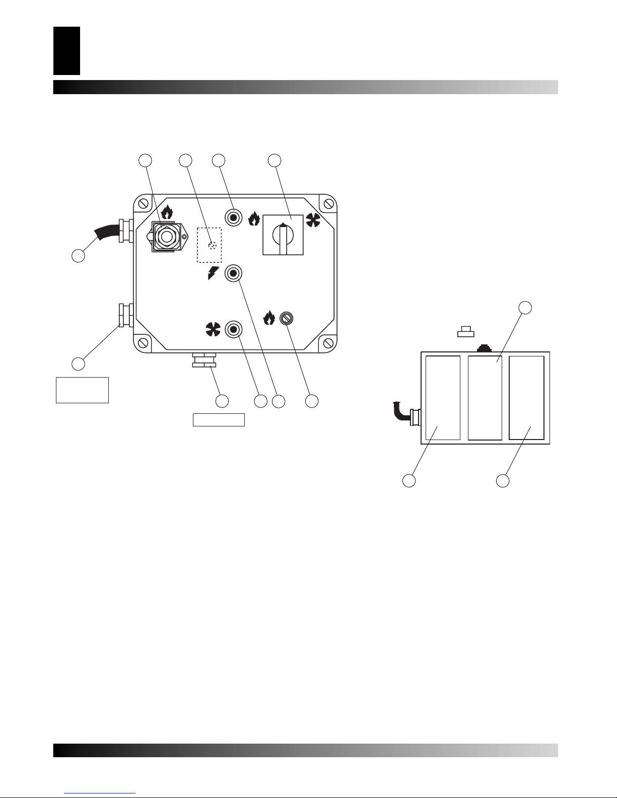
QUADRO COMANDI - CONTROL BOARD - KONTROLLTAFEL - TABLEAU DE
COMMANDE - TABLERO DE MANDOS
1. Spia tensone quadro - Control lamp - Kontrollampe - testigo
tensión tablero - Lampe temoin mise sous tension
7. Porta fusibile per bruciatore - Burner fuse holder - Sicherungschalter für brenner - Porta fusible para quemador
2. Interruttore - Control knob only - Schalter - Conmutador - Commutateur
8. Pressacabvo per termostato ambiente - Cable fastener for
room thermostat - Raumthermostat kabel führung - Prensa cable para de termostato ambiente - Presse etoupe
pour thermostat d’ambiance
3. Cavo alimentazione elettrica - Power cord - Elektro kabel Cable alimentación - Cable electrique alimentation
9. Spia termostato di sicurezza - Overheat thermostat control
lamp - Überhitzungschutz kontrollampe - Testigo termostato de seguridad - Lampe temoin securite de surchauffe
4. Presa per bruciatore - Burner plug - Sicherungschalter für brenner - Enchufe para quemador
10. Spia blocco ventilatore - Fan stop control lamp - Ventilator
“aus” kontrollampe - Testigo bloqueo ventilador - Lampe
temoin arret ventilateur
5. Termostato ventilatore - Fan thermostat - Luftregler - Termostato ventilador - Thermostat ventilateur
11. Riarmo ventilatore - Fan reset - Ventilator entriegelungs
schalter - Restablecimiento ventilador - Rearmement
ventilateur
6. Termostato di sicurezza a riarmo manuale - Limit thermostat
with manual restart - Sichereitsthermostat mit manueller entriegelung - Termostato de seguridad con restablecimiento manual
- Thermostat de securite a rearmement manual
12. Termostato di sovratemperatura - Overheat safety
thermostat - Überhitzungschutz Thermostat - Termostato
de sobretemperatura - Thermostat de securité de
surchauffe
GREEN 70
GREEN 115
GREEN 200
0
2
1
F
L2
L1
2
11
4
7
1
8 10
8
6
12
9
5
3
GREEN 70
GREEN 115
GREEN 200
Fig. 0
DESCRIPTION
Warning: Only the burners which are chosen and supplied by the manufacturer can be used. If another type
of burner is used the heater no longer complies with CE
regulations.
GREEN space heaters have been designed for use in small
to medium-sized rooms and buildings where a fi xed or mobile
heating system is required.
Heat is produced by combustion and the heat from the smoke
is transmitted to the fresh air through the metal walls of the
combustion chamber and the heat exchanger. The combustion
chamber is of the type where smoke circulates twice.
The air and smoke pass through separated ducts, both of which
are welded and sealed. When, after combustion, the waste gases have cooled, they are expelled through a duct which must
be connected to a chimney or chimney fl ue. The chimney or
chimney fl ue must be big enough to guarantee that the smoke
is expelled effi ciently.
The air which is used in combustion is aspirated directly from the
room or building which is being heated. It is therefore of utmost
importance that the room or building be properly ventilated so
that enough fresh air is circulating at all times.
GREEN heaters can operate with burners that are fuelled by
heating oil, methane (G20) or L.P.G. (butane G3O and propane
G31) of the ON-OFF type.
There are three safety devices which are activated in case of
serious malfunction. The Burner Control Device, which is mounted on the burner and has a restart button, automatically stops
the burner if the fl ame goes out. The Overhrat Thermostat, L2,
of the manuel restart type, is activated if the temperature of the
combustion chamber rises above the set maximum limit; the
warning light (9) lights up and the heater stops working. The
Thermal Relay, RM, is activated if the fan motor starts to use
more electrical current than the maximum permitted limit; the
warning light (10) lights up and the heater stops working.
If any of these safety devices are activated you should check
carefully what the problem actually is before pressing the restart
button and starting the heater off again (“OBSERVED F AULTS,
CAUSES AND REMEDIES”). Overheat safety thermostat, L1,
shuts down the heater if air fl ow is not suffi cient to cool off com-
bustion chamber: the heater will restart automatically as soon as
the heater has cooled down enough (the lamp(9) lights up and
then it cuts down).
GENERAL ADVICES
The space heater must be installed, set up and used in accordancewith existing laws.
Here are a few general guidelines which should be followed:
• Follow the instructions in this booklet very carefully;
• Don’t install the heater in places where there may be a risk of
fi re or explosion;
• Infl ammable material should be kept at a safe distance from
the heater (Minimum 3 meters);
• All fi re prevention regulations must be adhered to;
• The room or building which is being heated must be suffi ciently
ventilated so that the heater has enough air to function properly;
• The heater must be near a chimney or chimney fl ue and a sui-
table electric switchboard;
• Don’t let animals or children near the heater;
• After use make sure the disconnecting switch is off.
When using any type of space heater it is obligatory:
• not to exceed the maximum level of heat output of the furnace
(“TECHNICAL SPECIFICATION TABLE”);
• to make sure that there is adequate air circulation and air supplyto the heater and that nothing is obstructing the aspiration
and expulsion of air; movement of air may be obstructed in
various ways including placing covers or other objects on the
heater or positioning the heater too near a wall or other large
object. If the airfl ow is not adequate, the combustion chamber
will over heat and the overheat safety thermostat L1 will turn
the burner off and on continnously (“OBSERVED FAULTS,
CAUSES AND REMEDIES”).
INSTALLATION
Warning: The following operations must be carried out by
qualifi ed personnel only.
ELECTRICAL CONNECTIONS AND SETTINGS
Warning: The mains supply to the heater must be earthed
and have a magneto-thermal switch with differential.
The power cord must be connected to a switch board
which has a disconnecting switch.
Every space heater is supplied along with the safety and control
devices which are indispensable to the correct functioning of the
unit.The electric switchboard, burner, the fan thermostat, over
heat safety thermostat and the overheat thermostat with manual
restart have already been connected.
The following operations must now be carried out:
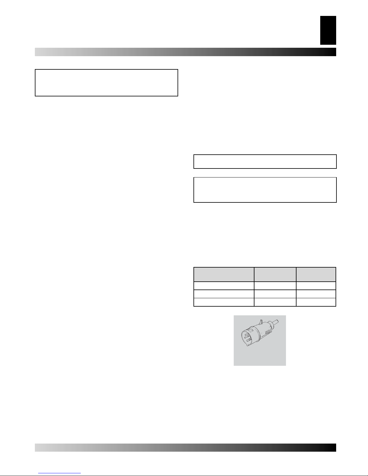
• Plug in the power cord having read the adhesive label which details electricity supply characteristics (Table 1). Table 2
shows the adhesive label on units which have three-phase
supply;
Model
M - M/C
Model
T - T/C
Number of phases 1 3
Tension 230 230/400
Frequency 50 50
• The burner must be connected to the fuel supply (“Burner Instruction Manual”);
• Connect the burner to the electricity supply with the burner
plug;
• Connect accessories such as the room thermostat or clock to
the unit’s electric switchboard: electric wire must be connected
by means of the cable fastener (8) to the terminals (6) and (7).
Having completed all these operations check carefully that all
electrical connections correspond to the wiring diagram. When
the heateris fi rst turned on you must check that the fan does not
use more current than the maximum permitted limit. Finally, to
HOT AIR GENERATOR
7
GB
Tab. 1
[V]
[Hz]
❏ 230V - 3 ~ - 50Hz
❏ 400V - 3 ~ - 50Hz
Tab. 2
 Loading...