

Page 1
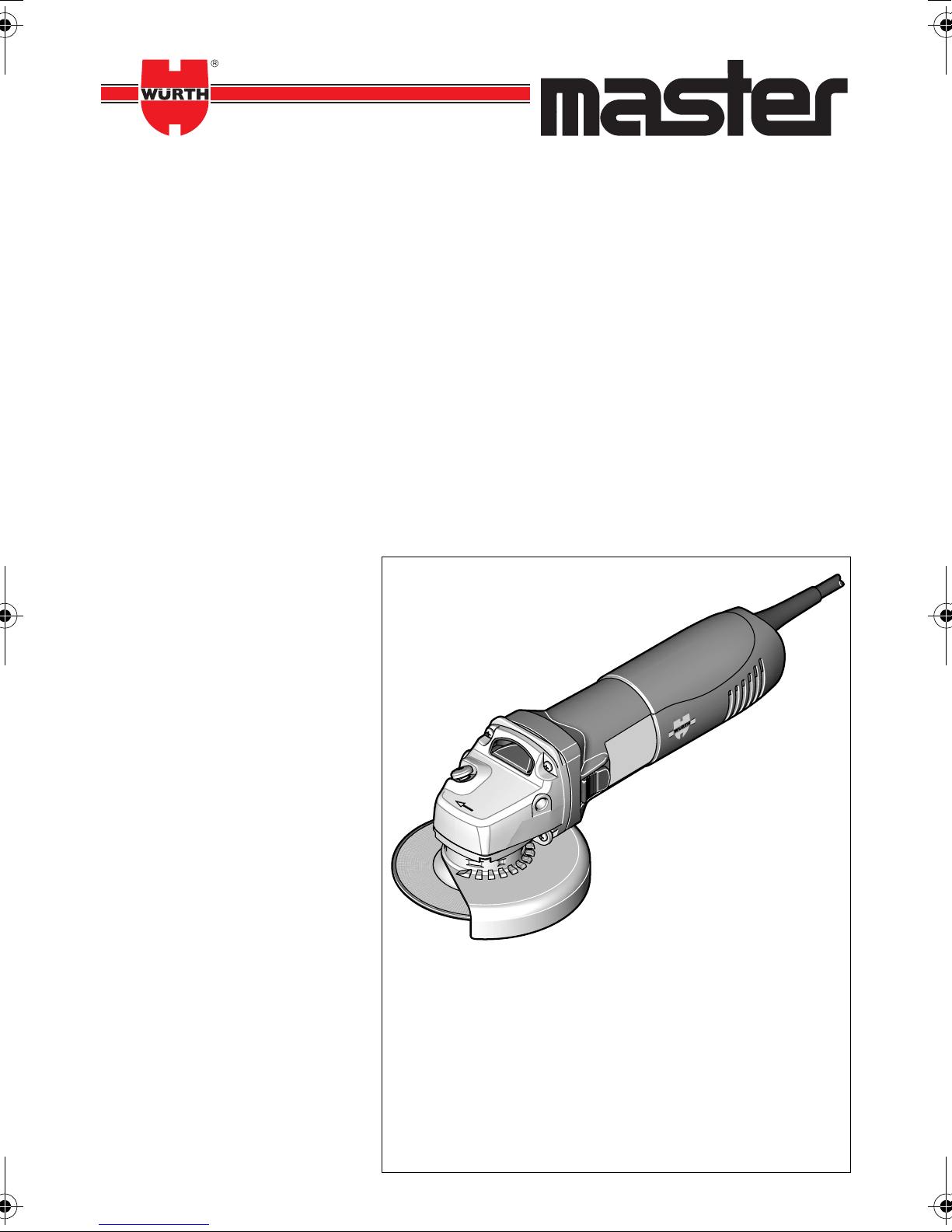
EWS 115
EWS 125-S
EWS 125-ES
EWS 14-125 S
EWS 14-150 S
Bedienungsanleitung
Operating instructions
Istruzioni d’uso
Instructions d’emploi
Instrucciones de servicio
Manual de instruções
Gebruiksaanwijzing
Betjeningsvejledning
Brukerveiledningen
Käyttöohje
Bruksanvisning
Οδηγία χειρισμού
Kullanım kılavuzu
Instrukcja obsługi
Használati utasítás
Návod k obsluze
Návod na používanie
Instrucţiuni de folosire
Navodilo za uporabo
Ръководство за
експлоатация
Kasutusjuhend
Naudojimo instrukcija
Lietošanas pamācība
Руководство по
эксплуатации
Page 2
1
2
3
4
5
6
78
9
10
11
12
13
14 14
15
18
16
17
1 609 929 L48 • 15.6.07
Page 3
For Your Safety
Read all safety warnings and all
instructions. Failure to follow the
warnings and instructions may result in
electric shock, fire and/or serious
injury.
❏ See data sheet for further safety warnings
and instructions.
Safety warnings that are common
for grinding, sanding, wire brush-
ing or abrasive cutting off opera-
tions
❏ This power tool is intended to function as
a grinder, sander, wire brush or cut-off
tool. Read all safety warnings, instructions, illustrations and specifications provided with this power tool. Failure to follow
all instructions listed below may result in electric
shock, fire and/or serious injury.
❏ This power tool is not recommended for
poslishing. Operations for which the power tool
was not designed may create a hazard and cause
personal injury.
❏ Do not use accessories which are not spe-
cifically designed and recommended by
the tool manufacturer. Just because the
accessory can be attached to your power tool, it
does not assure safe operation.
❏ The rated speed of the accessory must be
at least equal to the maximum speed
marked on the power tool. Accessories run-
ning faster than their rated speed can fly apart.
❏ The outside diameter and the thickness of
your accessory must be within the capacity
rating of your power tool. Incorrectly sized
accessories cannot be adequately guarded or
controlled.
❏ The arbor size of wheels, flanges, backing
pads or any other accessory must properly
fit the spindle of the power tool. Accessories
with arbor holes that do not match the mounting
hardware of the power tool will run out of balance, vibrate excessively and may cause loss of
control.
❏ Do not use a damaged accessory. Before
each use, inspect the accessory such as
abrasive wheels for chips and cracks,
backing pads for cracks, tears or excess
wear, wire brushes for loose or cracked
wires. If power tool or accessory is
dropped, inspect for damage or install an
undamaged accessory. After inspecting
and installing an accessory, position your-
self and bystanders away from the plane
of the rotating accessory and run the
power tool at maximum no-load speed for
one minute. Damaged accessories will nor-
mally break apart during this test time.
❏ Wear personal protective equipment.
Depending on application, use face
shield, safety goggles or safety glasses. As
appropriate, wear dust mask, hearing
protectors, gloves and shop apron capable of stopping small abrasive or workpiece fragments. The eye protection must be
capable of stopping flying debris generated by
various operations. The dust mask or respirator
must be capable of filtrating particles generated
by your operation. Prolonged exposure to high
intensity noise may cause hearing loss.
❏ Keep bystanders a safe distance away
from the work area. Anyone entering the
work area must wear personal protective
equipment. Fragments of workpiece or of a
broken accessory may fly away and cause injury
beyond immediate area of operation.
❏ Hold the power tool only by the insulated
gripping surfaces when performing an
operation where the cutting tool may contact hidden wiring or its own power cord.
Contact with a “live” wire will also make exposed
metal parts of the power tool “live” and shock the
operator.
❏ Position the cord clear of the spinning
accessory. If you lose control of the power tool,
the cord may be cut or snagged and your hand
or arm may be pulled into the spinning accessory.
❏ Never lay the power tool down until the
accessory has come to a complete stop. The
spinning accessory may grab the surface and pull
the power tool out of your control.
❏ Do not run the power tool while carrying it
at your side. Accidental contact with the spin-
ning accessory could snag your clothing, pulling
the accessory into your body.
❏ Regularly clean the power tool’s air vents.
The motor’s fan will draw the dust inside the
housing and excessive accumulation of powdered metal may cause electrical hazards.
❏ Do not operate the power tool near flam-
mable materials. Sparks could ignite these
materials.
❏ Do not use accessories that require liquid
coolants. Using water or other liquid coolants
may result in electrocution or shock.
14–English
1 609 929 L48 • 15.6.07
Page 4

Kickback and related warnings
❏ Kickback is a sudden reaction to a pinched or
snagged rotating wheel, backing pad, brush or
any other accessory. Pinching or snagging
causes rapid stalling of the rotating accessory
which in turn causes the uncontrolled power tool
to be forced in the direction opposite of the
accessory’s rotation at the point of the binding.
For example, if an abrasive wheel is snagged or
pinched by the workpiece, the edge of the wheel
that is entering into the pinch point can dig into
the surface of the material causing the wheel to
climb out or kick out. The wheel may either jump
toward or away from the operator, depending on
direction of the wheel’s movement at the point of
pinching. Abrasive wheels may also break under
these conditions.
Kickback is the result of power tool misuse
and/or incorrect operating procedures or conditions and can be avoided by taking proper precautions as given below.
❏ Maintain a firm grip on the power tool
and position your body and arm to allow
you to resist kickback forces. Always use
auxiliary handle, if provided, for maximum control over kickback or torque
reaction during start-up. The operator can
control torque reactions or kickback forces, if
proper precautions are taken.
❏ Never place your hand near the rotating
accessory. The accessory may kickback over
your hand.
❏ Do not position your body in the area
where the power tool will move if kickback
occurs. Kickback will propel the tool in the direc-
tion opposite to the wheel’s movement at the
point of snagging.
❏ Use special care when working corners,
sharp edges, etc. Avoid bouncing and
snagging the accessory. Corners, sharp
edges or bouncing have a tendency to snag the
rotating accessory and cause loss of control or
kickback.
❏ Do not attach a saw chain woodcarving
blade or toothed saw blade. Such blades
create frequent kickback and loss of control over
the power tool.
Additional safety instructions for
grinding and cutting off opera-
tions
❏ Always use guard designed for the type of
wheel you are using. The guard must be
securely attached to the power tool and
positioned for maximum safety, so the
least amount of wheel is exposed towards
the operator. The guard helps to protect oper-
ator from broken wheel fragments and accidental contact with wheel.
❏ Use only wheel types that are recom-
mended for your power tool and the specific guard designed for the selected
wheel. Wheels for which the power tool was not
designed cannot be adequately guarded and are
unsafe.
❏ Wheels must be used only for recom-
mended applications. For example: do not
grind with the side of the cut-off wheel. Abrasive
cut-off wheels are intended for peripheral grinding; side forces applied to these wheels may
cause them to shatter.
❏ Always use undamaged wheel flanges
that are of correct size and shape for your
selected wheel. Proper wheel flanges support
the wheel thus reducing the possibility of wheel
breakage. Flanges for cut-off wheels may be different from grinding wheel flanges.
❏ Do not use worn down wheels from larger
power tools. Wheels intended for larger power
tools are not suitable for the higher speed of a
smaller tool and may burst.
Additional safety warnings specific
for abrasive cutting off operations
❏ Do not “jam” the cut-off wheel or apply
excessive pressure. Do not attempt to
make an excessive depth of cut. Overstress-
ing the wheel increases the loading and susceptibility to twisting or binding of the wheel in the cut
and the possibility of kickback or wheel breakage.
❏ Do not position your body in line with and
behind the rotating wheel. When the wheel,
at the point of operation, is moving away from
your body, the possible kickback may propel the
spinning wheel and the power tool directly at
you.
1 609 929 L48 • 15.6.07
English–15
Page 5
❏ When wheel is binding or when interrupt-
ing a cut for any reason, switch off the
power tool and hold the power tool
motionless until the wheel comes to a
complete stop. Never attempt to remove
the cut-off wheel from the cut while the
wheel is in motion, otherwise kickback
may occur. Investigate and take corrective
action to eliminate the cause of wheel binding.
❏ Do not restart the cutting operation in the
workpiece. Let the wheel reach full speed
and carefully reenter the cut. The wheel may
bind, walk up or kickback if the power tool is
restarted in the workpiece.
❏ Support panels or any oversized work-
piece to minimize the risk of wheel pinching and kickback. Large workpieces tend to
sag under their own weight. Supports must be
placed under the workpiece near the line of cut
and near the edge of the workpiece on both sides
of the wheel.
❏ Use extra caution when making a “pocket
cut” into existing walls or other blind
areas. The protruding wheel may cut gas or
water pipes, electrical wiring or objects that can
cause kickback.
Safety warnings specific for sand-
ing operations
❏ When sanding, do not use excessively
oversized sanding disc paper. Follow
manufacturers recommendations, when
selecting sanding paper. Larger sanding
paper extending beyond the sanding pad
presents a laceration hazard and may cause
snagging, tearing of the disc, or kickback.
Safety warnings specific for wire
brushing operations
❏ Be aware that wire bristles are thrown by
the brush even during ordinary operation.
Do not overstress the wires by applying
excessive load to the brush. The wire bristles
can easily penetrate light clothing and/or skin.
❏ If the use of a guard is recommended for
wire brushing, do not allow any interference of the wire wheel or brush with the
guard. Wire wheel or brush may expand in
diameter due to work load and centrifugal
forces.
Additional safety warnings
Wear safety goggles.
❏ Use suitable detectors to determine if util-
ity lines are hidden in the work area or
call the local utility company for assistance. Contact with electric lines can lead to fire
and electric shock. Damaging a gas line can lead
to explosion. Penetrating a water line causes
property damage or may cause an electric shock.
❏ When working stone, use dust extraction.
The vacuum cleaner must be approved for
the extraction of stone dust. Using this
equipment reduces dust-related hazards.
❏ Use a cutting guide when cutting stone.
Without sideward guidance, the cutting disc can
jam and cause kickback.
❏ When working with the machine, always
hold it firmly with both hands and provide
for a secure stance. The power tool is guided
more secure with both hands.
❏ Secure the workpiece. A workpiece clamped
with clamping devices or in a vice is held more
secure than by hand.
❏ Do not work materials containing asbes-
tos. Asbestos is considered carcinogenic.
❏ Take protective measures when dust can
develop during working that is harmful to
one’s health, combustible or explosive.
Example: Some dusts are regarded as carcinogenic. Wear a dust mask and work with dust/chip
extraction when connectable.
❏ Keep your workplace clean. Blends of mate-
rials are particularly dangerous. Dust from light
alloys can burn or explode.
❏ Never use the machine with a damaged
cable. Do not touch the damaged cable
and pull the mains plug when the cable is
damaged while working. Damaged cables
increase the risk of an electric shock.
❏ Use only original Würth accessories.
16–English
1 609 929 L48 • 15.6.07
Page 6

Intended Use
Product Features
The machine is intended for cutting, roughing, and
brushing metal and stone materials without using
water.
For cutting metal, a special protection guard for cutting (accessory) must be used.
With approved sanding tools, the machine can be
used for sanding with sanding discs.
For damage caused by usage other than intended,
the user is responsible.
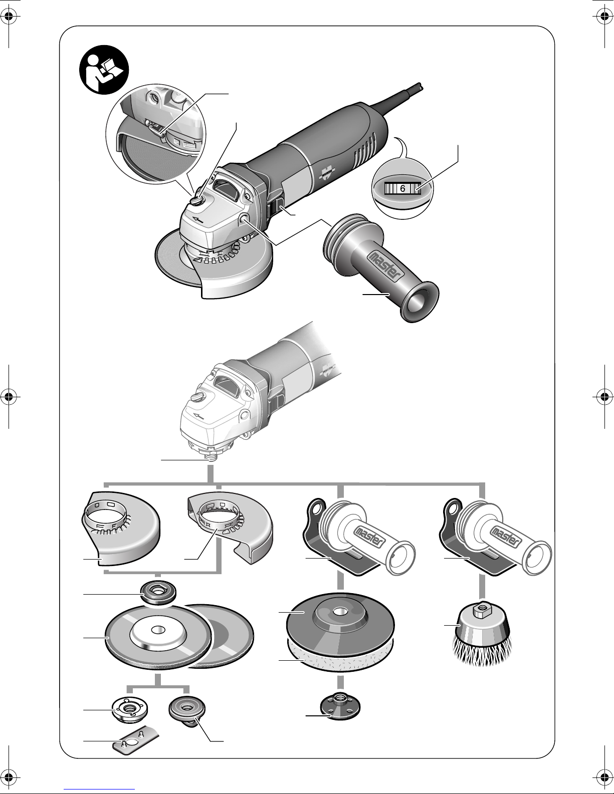
While reading the operating instructions, unfold the
graphics page for the machine and leave it open.
The numbering of the product features refers to the
illustration of the power tool on the graphics page.
1 Release lever for protection guard
2 Spindle lock button
3 Thumbwheel for speed preselection
(EWS 125-ES)
4 On/Off switch
5 Auxiliary handle
6 Grinder spindle
7 Protection guard for sanding
8 Protection guard for cutting*
9 Mounting flange with O-ring
10 Grinding/cutting disc*
11 Clamping nut
12 Two-pin spanner
13 Quick-clamping nut**
14 Hand guard*
15 Rubber sanding plate*
16 Sanding sheet*
17 Round nut*
18 Cup brush*
*The accessories illustrated or described are not
included as standard delivery.
**Depending on version
1 609 929 L48 • 15.6.07
English–17
Page 7

Technical Data
Angle Grinder EWS
115
EWS
125-S
EWS
125-ES
EWS
14-125 S*
EWS
14-150 S*
Art. No. 0 702 ... 471 X.. 472 X.. 473 X.. 476 X.. 477 X..
Rated power input W 800 1100 1100 1400 1400
Output power W 500 660 660 820 820
No-load speed rpm 11000 11000 2800
11000 9300
–11000
Grinding disc diameter, max. mm 115 125 125 125 150
Thread of grinder spindle M 14 M 14 M 14 M 14 M 14
Kickback stop – z z z z
Restarting protection – zzzz
Reduced starting current – z z z z
Constant electronic control – zzzz
Speed preselection – – z – –
Weight according to
EPTA-Procedure 01/2003 kg 1.9 2.0 2.0 2.2 2.3
Protection class /II /II /II /II /II
The values given apply for nominal voltages [U] of 230/240 V.
*Not available in all countries.
Noise/Vibration Information
Measured values determined according to EN 60745. 0 702 ... 471 X.. 472 X..
477 X..
473 X..
476 X..
Typically the A-weighted noise levels of the product are:
Sound pressure level
Sound power level
Uncertainty K=
dB(A)
dB(A)
dB
91
102
91
102
3
3
91
102
Wear hearing protection!
Vibration total values (triax vector sum) determined according to
EN 60745:
Surface grinding:
Vibration emission value a
Uncertainty K=
Disk sanding:
Vibration emission value a
Uncertainty K=
WARNING
The vibration emission level given in this information sheet has been measured in accordance with a standardised test given in EN 60745 and may be used to compare one tool
h
h
m/s
m/s
m/s
m/s
2
2
2
2
5.5
2.0
3.0
1.5
8.5
2.0
3.0
1.5
7.0
2,0
3.0
1.5
with another.
The vibration emission level will vary because of the ways in which a power tool can be used and may
increase above the level given in this information sheet. This could lead to a significant underestimate of
exposure when the tool is used regularly in such a way.
Note: To be accurate, an estimation of the level of exposure to vibration experienced during a given period
of work should also take into account the times when the tool is switched off and when it is running but not
actually doing the job. This may significantly reduce the exposure level over the total working period.
3
18–English
1 609 929 L48 • 15.6.07
Page 8

Declaration of Conformity
We declare under our sole responsibility that the
product described under “Technical Data” is in conformity with the following standards or standardization documents: EN 60745 according to the
provisions of the directives 89/336/EEC, 98/37/EC
(until Dec. 28, 2009), 2006/42/EG (from Dec. 29,
2009 on).
07
Adolf Würth GmbH & Co. KG
P. Zürn R. Bauer
Mounting the Protective Devices
❏ Before any work on the machine itself,
pull the mains plug.
Protection Guard for Sanding
Place the protection guard 7
onto the spindle collar as
shown in the illustration. The
triangle marks on the protection guard must correspond
with the respective marks on
the gear case.
Press the protection guard 7
onto the spindle collar until
the shoulder of the protection
guard is seated against the
flange of the machine, and
turn the protection guard
until it can clearly be heard to
engage.
Adjust the position of the protection guard 7 to the
requirements of the work process. For this, press the
release lever 1 upward and turn the protection
guard 7 to the required position.
❏ Adjust the protection guard 7 in such a
manner that sparking is prevented in the
direction of the operator.
❏ The protection guard 7 may be turned
only upon actuation of the release lever 1!
Otherwise the power tool may not continue to be used under any circumstances
and must be taken to an after-sales service agent.
Note: The encoding keys on the protection guard 7
ensure that only a protection guard that fits the
machine type can be mounted.
Protection Guard for Cutting
❏ For cutting metal, always work with the
protection guard for cutting 8.
The protection guard for cutting 8 is mounted in the
same manner as the protection guard for sanding 7.
Auxiliary Handle
❏ Operate your machine only with the auxil-
iary handle 5.
Screw the auxiliary handle 5 on the right or left of the
machine head depending on the working method.
Vibration-dampening Auxiliary
Handle
The vibration-dampening auxiliary handle reduces
the vibrations, making operation more comfortable
and secure.
❏ Do not make any alterations to the auxil-
iary handle.
Do not continue to use an auxiliary handle if
it is damaged.
Hand Guard
❏ For operations with the rubber sanding
plate 15 or with the cup brush/wheel
brush/flap disc, always mount the hand
guard 14.
The hand guard 14 is fastened with the auxiliary
handle 5.
Mounting the Grinding Tools
❏ Before any work on the machine itself,
pull the mains plug.
❏ Grinding and cutting discs become very
hot while working; do not touch until they
have cooled.
Clean the grinder spindle 6 and all parts to be
mounted.
For clamping and loosening the grinding tools, lock
the grinder spindle with the spindle lock button 2.
❏ Actuate the spindle lock button only when
the grinder spindle is at a standstill. Oth-
erwise, the machine may become damaged.
Grinding/Cutting Disc
Pay attention to the dimensions of the grinding tools.
The mounting hole diameter must fit the mounting
flange without play. Do not use reducers or adapters.
1 609 929 L48 • 15.6.07
English–19
Page 9

When using diamond cutting discs, pay attention
that the direction-of-rotation arrow on the diamond
cutting disc and the direction of rotation of the
machine (see direction-of-rotation arrow on the
machine head) agree.
See graphics page for the mounting sequence.
To fasten the grinding/cutting disc, screw on the
clamping nut 11 / 13 and tighten with the two-pin
spanner; see Section “
❏ After mounting the grinding tool and
before switching on, check that the grinding tool is correctly mounted and that it
can turn freely. Make sure that the grinding tool does not graze against the protection guard or other parts.
Quick-clamping Nut
An O-ring (plastic part) is inserted
in the mounting flange 9 around
the centring collar. If the O-ring
is missing or is damaged, it
must in all cases be replaced
before the mounting flange 9 is
mounted.
”.
Flap Disc
❏ For operations with the rubber sanding
plate 15 or with the cup brush/wheel
brush/flap disc, always mount the hand
guard 14.
Rubber Sanding Plate
❏ For operations with the rubber sanding
plate 15 or with the cup brush/wheel
brush/flap disc, always mount the hand
guard 14.
See graphics page for the mounting sequence.
Screw on the round nut 17 and tighten with the two-
pin spanner.
Cup Brush/Disc Brush
❏ For operations with the rubber sanding
plate 15 or with the cup brush/wheel
brush/flap disc, always mount the hand
guard 14.
See graphics page for the mounting sequence.
The cup brush/disc brush must be able to be
screwed onto the grinder spindle until it rests firmly
against the grinder spindle flange at the end of the
grinder spindle threads. Tighten the cup brush/disc
brush with an open-end spanner.
Quick-clamping Nut
❏ Use the quick-clamping nut only for grind-
ing/cutting discs with a diameter of up to
125 mm (max.).
X
After mounting the mounting flange and grinding/cutting disc, the clear thread length “X of the
grinding spindle” must be at least 4 mm.
Lock the grinding spindle with the spindle lock button 2. Fold up the clip of the quick-clamping nut 13
and manually screw the nut onto the grinding spindle in clockwise direction 6 until firmly seated on the
grinding/cutting disc. Fold the clip down again.
To release, fold up the clip of the quick-clamping nut
13 and manually unscrew the nut off of the locked
spindle in anticlockwise direction. If necessary, the
quick-clamping nut 13 can also be loosened with
the corresponding two-pin spanner 12 after folding
up the clip.
Approved Grinding Tools
All grinding tools mentioned in these operating
instructions can be used.
The permissible speed [rpm] or the circumferential
speed [m/s] of the grinding tools used must at least
match the values given in the table.
Therefore, observe the permissible rotational/cir-
cumferential speed on the label of the grinding
tool.
max.
[mm] [mm]
Dbd[rpm][m/s]
d
b
D
d
b
D
115
125
D
150
115
125
75 30 M 14 11000 45
6
22.2
6
22.2
6
22.2
––
11000
11000
9300
11000
110008080
80
80
80
20–English
1 609 929 L48 • 15.6.07
Page 10

Rotating the Machine Head
❏ Before any work on the machine itself,
pull the mains plug.
The machine head
can be rotated with
respect to the
machine housing in
90° steps. In this
manner, the On/Off
switch can be brought
into a more convenient position for special working
situations, e.g. for
left-handed persons.
Completely unscrew the four screws. Rotate the
machine head carefully, without removing it
from the housing, to the new position. Screw in
and tighten the four screws again.
Starting Operation
❏ Observe correct mains voltage! The volt-
age of the power source must agree with
the voltage specified on the nameplate of
the machine. Power tools marked with
230 V can also be operated with 220 V.
When operating the machine with power from
mobile generators that do not have sufficient reserve
capacity or are not equipped with suitable voltage
control with starting current amplification, loss of
performance or untypical behavior can occur upon
switching on.
Please observe the suitability of the power generator
being used.
Kickback stop (EWS 125-S/
EWS 125-ES/ EWS 14-125 S/
EWS 14-150 S)
In case of a sudden drop in speed, e.g. jamming
while carrying out a separating cut, the power supply
to the motor is interrupted.
To restart the operation, switch the On/Off
switch 4 to the Off position and start the machine
again.
Restarting protection (EWS 125-S/
EWS 125-ES/ EWS 14-125 S/
EWS 14-150 S)
The restarting protection feature prevents uncontrolled restarting of the machine after an interruption
in the power supply.
To restart the operation, switch the On/Off
switch 4 to the Off position and start the machine
again.
Reduced starting current
(EWS 125-S/EWS 125-ES/
EWS 14-125 S/EWS 14-150 S)
The electronic reduced starting current limits the
power consumption when switching the tool on and
enables operation from a 13 ampere fuse.
Constant Electronic Control
(EWS 125-S/EWS 125-ES/
EWS 14-125 S/EWS 14-150 S)
Constant electronic control holds the speed constant
at no-load and under load, and ensures uniform
working performance.
Switching On and Off
To start the power tool, push the On/Off switch 4
forwards.
To lock the On/Off switch 4, press the On/Off
switch 4 down at the front until it latches.
To switch off the power tool, release the On/Off
switch 4 or, if it is locked, briefly push down the back
of the On/Off switch 4 and then release it.
❏ Check grinding tools before using. The
grinding tool must be mounted properly
and be able to move freely. Carry out a
test run for at least one minute with no
load. Do not use damaged, out-of-centre
or vibrating grinding tools. Damaged grind-
ing tools can burst and cause injuries.
1 609 929 L48 • 15.6.07
English–21
Page 11

Speed preselection (EWS 125-ES)
The required speed can be preselected with the thumbwheel 3 (also while running).
The data in the following table are recommended values.
Material Application Accessory Thumbwheel 3
Metal Removing paint Sanding disc 2 – 3
Wood, metall Brushing, rust removal Cup brush, sanding disc 3
Metal, masonry Sanding Sanding disc 4– 6
Metal Rough grinding Sanding disc 6
Operating Instructions
❏ Exercise caution when cutting slots in
structural walls; see Section “Information
on Structures ”.
❏ Clamp the workpiece if it does not remain
stationary due to its own weight.
❏ Do not strain the machine so heavily that
it comes to a standstill.
❏ Grinding and cutting discs become very
hot while working; do not touch until they
have cooled.
Rough Grinding
❏ Never use a cutting disc for roughing.
The best roughing results are achieved when setting
the machine at an angle of 30° to 40°. Move the
machine back and forth with moderate pressure. In
this manner, the workpiece will not become too hot,
does not discolour and no grooves are formed.
Flap Disc
With the flap disc (accessory), curved surfaces and
profiles can be worked.
Flap discs have a considerably higher service life,
lower noise levels and lower sanding temperatures
than conventional sanding sheets.
Cutting Metal
❏ For cutting metal, always work with the
protection guard for cutting 8.
When cutting, work with moderate feed, adapted to
the material being cut. Do not exert pressure onto
the cutting disc, tilt or oscillate the machine.
Do not reduce the speed of running down cutting
discs by applying sideward pressure.
The machine must
always work in an upgrinding motion.
Otherwise, the danger exists of it being
pushed uncon-
trolled out of the cut.
When cutting profiles
and square bar, it is
best to start at the
smallest cross section.
Information on Structures
Slots in structural walls are subject to the Standard
DIN 1053 Part 1, or country-specific regulations.
These regulations are to be observed under all circumstances. Before beginning work, consult the
responsible structural engineer, architect or the construction supervisor.
Maintenance and Cleaning
❏ Before any work on the machine itself,
pull the mains plug.
❏ For safe and proper working, always keep
the machine and ventilation slots clean.
❏ In extreme working conditions, conductive
dust can accumulate in the interior of the
machine when working with metal. The
protective insulation of the machine can
be degraded. The use of a stationary
extraction system is recommended in such
cases as well as frequently blowing out the
ventilation slots and installing a residual
current device (RCD).
If the machine should fail despite the care taken in
manufacturing and testing procedures, repair
should be carried out by a Würth master-Service.
22–English
1 609 929 L48 • 15.6.07
Page 12

In all correspondence and spare parts orders, please
always include the article number given on the type
plate of the machine.
The current spare parts list for this power tool can be
viewed in the Internet under
“http://www.wuerth.com/partsmanager”
or be requested from your next Würth branch office.
Guarantee
For this Würth power tool, we provide a guarantee
in accordance with the legal/country-specific regulations from the date of purchase (verified by invoice
or delivery document). Damage that has occurred
will be corrected by replacement or repair.
Damage caused by normal wear, overloading or
improper handling is excluded from the guarantee.
Claims can only be accepted if the power tool is sent
undisassembled to a Würth branch office, your
Würth sales representative or a customer service
agent for Würth power tools.
Disposal
The machine, accessories and packaging should be
sorted for environmental-friendly recycling.
Only for EC countries:
Do not dispose of power tools into household waste!
According to the European Guideline
2002/96/EC for Waste Electrical and
Electronic Equipment and its implementation into national right, power tools that are no
longer usable must be collected separately and disposed of in an environmentally correct manner.
Subject to change without notice.
1 609 929 L48 • 15.6.07
English–23
Page 13

Würth worldwide:
Würth Albania Ltd.
Rr. Asim Vokshi
Pall 49/1 Ap. 9
AL-Tirana
Albania
Tel. ++355/42/29748
Fax ++355/42/29748
wuerthal@icc.al.eu.org
Würth Armenia Co. Ltd.
63 Tigran Mets Ave.
AM-375005 Yerevan
Armenia
Tel. ++3741/559970
Fax ++3741/559972
wuerth@arminco.com
Würth Handelsges.m.b.H.
Würth Strasse 1
AT-3071 Böheimkirchen
Austria
Tel. ++43/2743/70700
Fax ++43/2743/70703333
info@wuerth.at
Würth Australia Pty Ltd
4 Redwood Drive
AU-Dingley VIC 3172
Australia
Tel. ++61/3/95517244
Fax ++61/3/955 12994
info@wurth.com.au
Wurth Aztur Ltd
Mir Galal Str.63.
AZ-370134 Baku
Azerbaijan
Tel. ++994/12/601934
Fax ++994/12/601934
wurth@azdata.net
Wurth BH d.j.l.
Dzemal Biedia 162
BA-71000 Sarajevo,BIH
Bosnia
Tel. ++387/33/461770
Fax ++387/33/461825
Würth Belux N.V.
Everdongenlaan 29
BE-2300 Turnhout
Belgium
Tel. ++32/14/445566
Fax ++32/14/423077
info@wurth.be
Wuerth Bulgaria EOOD
Iskarsko Chaussee Boul. 12
BG-1592 Sofia
Bulgaria
Tel. ++359/2/9659955
Fax ++359/2/9659966
wuerth_bg@ibm.net
Würth Belarus Ltd.
Botanitscheskaja Str. 5a-603
BY-220038 Minsk
Belarus
Tel. ++375/172/363919
Fax ++375/172/852512
wuerthbel@open.by
Würth AG
Dornwydenweg 11
CH-4144 Arlesheim
Switzerland
Tel. ++41/61/7059111
Fax ++41/61/7059494
infos@wuerth-ag.ch
Würth Guangzhou
International Trading Co., Ltd.
Room 601, North Tower,
Nantian Building,
3 Jiangong Road
Tianhe High and New Technology
Industry Development Zone
CN-510665 Guangzhou
China
Tel. ++86/20/85552840
Fax ++86/20/855550245
wurthgz@public.guangzhou.gd.cn
Würth Hong Kong Co. Ltd.
Unit B 6/f Prince Ind Bidg
106 King Fuk St.,
San Po Kong, Kowloon
CN-Hong Kong
China
Tel. ++8/52/27508118
Fax ++8/52/27530084
info@wuerth-hk.com
Wuerth China-Shanghai
Langsheng Trading Co., Ltd.
2nd Floor (West)
No. 18 Factory Site
No. 481 Gui Ping Road
CN-200233 Shanghai
China
Tel. ++86/21/64951418
Fax ++86/21/64848610
wuerthcn@public3.sta.net.cn
Würth Tianjin International
Trade Co., Ltd.
Jie Fang Nan Lu Str. 518-1
CN-300221 Tianjin
China
Tel. ++86/22/88242263
Fax ++86/22/88243813
tjwuerth@public.tpt.tj.cn
Wuerth Cyprus LTD
Strovolos industrial estate
P.O. Box 8899
CY-2083 Nicosia
Cyprus
Tel. ++357/2/512086
Fax ++357/2/512091
wuerthcy@cytanet.com.cy
Würth, spol. s r.o.
Sazecská 2
CZ-10800 Praha 10
Czech Republic
Tel. ++420/2/72106111
Fax ++420/2/72106119
info@wuerth.cz
Adolf Würth GmbH & Co. KG
Postfach
D-74650 Künzelsau
Reinhold-Würth-Str. 12-16
DE-74653 Künzelsau
Germany
Tel. ++49/7940/15-0
Fax ++49/7940/15-1000
info@wuerth.com
Würth Danmark A/S
Montagevej 6
DK-6000 Kolding
Denmark
Tel. ++45/79/323232
Fax ++45/75/517250
Würth Estonia AS
Liimi 3 A
EE-10621 Tallinn
Estonia
Tel. ++372/6563509
Fax ++372/6563494
wuerth@wuerth.ee
Würth Egypt for Trading S.A.E.
27th. Km Alexandria Cairo Desert
Road, Behind Mercedes
EG-Amriya Alexandria
Egypt
Tel. ++2/03/4700432
Fax ++2/03/4700432
wurth@wurthegypt.com
Würth España S.A.
Poligono Riera de Caldes
Carrer Dels Joiers 21-23
ES-08184 Palau de Plegamans
Barcelona
Spain
Tel. ++34/93/8629500
Fax ++34/93/8646203
webmaster@wurth.es
Würth Oy
Herajoki
FI-11710 Riihimäki
Finland
Tel. ++358/19/7701
Fax ++358/19/729010
Würth France S.A.
Z.I. Ouest
Rue Georges Besse
FR-67158 Erstein Cedex
France
Tel. ++33/3/88645300
Fax ++33/3/88646200
Wurth U.K. Ltd.
1 Centurion Way
Erith
GB-Kent DA 18 4 AE
Great Britain
Tel. ++44/208/3196000
Fax ++44/208/3196400
info@wurth.co.uk
Würth Georgia Ltd.
Marshal Gelovani Avenue 36
GE-380059 Tbilisi
Georgia
Tel. ++995/32/530610
Fax ++995/32/250610
gewuerth@caucasus.net
Würth Hellas S.A.
23. Klm. National Road
Athens-Lamia
145 68 Krioneri Attikis
P.O. Box 51877
Attikis
GR-145 02 Agios Stefanos Attikis
Greece
Tel. ++30/1/6290800
Fax ++30/1/8134756
info@wurth.gr
Würth-Hrvatska d.o.o.
Franje Lucica 23/III
HR-10000 Zagreb
Croatia
Tel. ++385/1/3498784
Fax ++385/1/3498783
wurth.hrvatska@zg.hinet.hr
Würth Szereléstechnika KFT
Gyár utca 2
HU-2040 Budaörs
Hungary
Tel. ++36/23/418130
Fax ++36/23/421777
wuerth@wuerth.hu
PT Wuerth Indah
JI. Meruya Ilir Raya No. 82 A-B
ID-Jakarta 11360
Indonesia
Tel. ++62/21/5860036
Fax ++62/21/5861043
wuerth@idola.net.id
Würth Ireland Ltd.
Monaclinoe Industrial Estate
Ballysimon Road
IR-Limerick
Ireland
Tel. ++353/61/412911
Fax ++353/61/412428
Würth Israel Ltd.
Alon Hatavor 2
Zone 1
IL-Caesarea Industrial Park
P.O. Box 3585
IL-Caesarea Industrial Park
Zip 38900
Israel
Tel. ++972/4/6273939
Fax ++972/4/6270999
Wuerth India Pvt. Ltd.
33, Santosh Building,
Marol Co-operative Industrial
Estate,
M V Road, Andheri (East)
IN-Mumbai 400 059
India
Tel. ++91/22/8507023
Fax ++91/22/8507020
wuerth@bom4.vsnl.net.in
Würth Teheran Ltd.
Pasdaran St.-Corner of Negarestane 5-No.183
IR-16619 Teheran-Iran
Iran
Tel. ++98/21/2842828
Fax ++98/21/2856171
wuerthtehran@irost.com
Würth á Íslandi ehf.
Veslurhraun 5
IS-210 Garðabær
Iceland
Tel. ++354/5302000
Fax ++354/5302001
ebse@wurth.is
Würth S.r.l. - GmbH
Via Stazione, 51
I - 39044 Egna (BZ)
Tel. ++39/0471/828111
Fax ++39/0471/828600
vendite@wuerth.com
Wurth – Jordan Co. Ltd.
Al-yadoudeh
P.O. Box 951
JO-Amman-11592
Jordan
Tel. ++962/6/4122512
Fax ++962/6/4122510
wurthjor@go.com.jo
Würth Japan Co., Ltd.
MT Building
33 Sanmaicho, Kanagawa-ku
JP-Yokohama 221-0862
Japan
Tel. ++81/45/4884186
Fax ++81/45/4884187
sat_ueda@wuerth.co.jp
jun_ando@wuerth.co.jp
Würth Nippon GmbH & Co. KG
6F Tsuruga Bldg., 1-29-15
Shinyokohama, Kohoku-Ku
JP-Yokohama 222-0033
Japan
Tel. ++81/45/4704633
Fax ++81/45/4704621
jj.wn@poem.ocn.ne.jp
Wuerth Kenya Ltd.
P.O. BOX 16751
Meru Road
KE-Mombasa
Kenya
Tel. ++254/11/312403
Fax ++254/11/312437
wuerth@africaonline.co.ke
Würth Foreign Swiss
Company Ltd.
3 Erkindik Boulevard
KG-Bishkek, 720040
Kyrgyzstan
Tel. ++996/312/227976
Fax ++996/312/661025
wurth@imfiko.bishkek.su
Page 14

Würth Kosova
No. 36 Pashe Dibra
Bregu i diellit
Prishtina
Tel. ++377/44/186514
wurthkosova@hotmail.com
Wurth Korea Co. Ltd.
128-1, O-Keum Dong,
KR-Song Pa-Gu, Seoul,
Korea (138-859)
South Korea
Tel. ++82/2/4009311
Fax ++82/2/4009315
wurth-kr@wurth.co.kr
Wuerth Kazakhstan Ltd.
Abai 125, 2nd floor
KZ-480008, Almaty
Kazakhstan
Tel. ++7/3272/622432
Fax ++7/3272/622495
wurthkaz@kaznet.kz
Würth Lietuva
Dariaus ir Gireno 21
LT-2038 Vilnius
Lithuania
Tel. ++370/2/263045
Fax ++370/2/264108
info@wurth.lt
Würth Reinsurance
Company, S.A.
B.P. 2217
L-1022 Luxembourg
Siège social
65, Avenue de la gare
LU-1611 Luxembourg
Tel. ++352/494177
Fax ++352/494188
Würth Maroc SARL
48 Avenue Pasteur
MA-Casablanca 20150
Marocco
Tel. ++212/2/2405700
Fax ++212/2/2405706
Würth Moldova Ltd.
b-dul Stefan cel Mare, nr 4
Hotel National
MD-Chisinau
Moldavia
Tel. ++373/2/540398
Fax ++373/2/540398
Würth Makedonien GmbH
ul. Gorce Petrov 108a
MK-91000 Skopje
Macedonia
Tel. ++389/233/2230
Fax ++389/233/2083
wurthmak@unet.com.mk
Würth Caraibes Sarl
Z.I. Cocotte Canal
MQ-97224 Ducos-Martinique
Tel. ++596/560701
Fax ++596/564369
wurth.caraibes@wanadoo.fr
Würth Limited
Würth House
Triq il-Masgar
MT-Qormi QRM09
Malta
Tel. ++356/494604
Fax ++356/441081
wuerth@maltanet.net
Wuerth (Malaysia) Sdn. Bhd.
6, Jalan Permas 9/13
Taman Permas Jaya
MY-81750 Masai Johor
Malaysia
Tel. ++60/7/3876280
++60/7/3881712
Fax ++60/7/3884391
wuerth@po.jaring.my
Würth Nederland B.V.
Moeskampweg 13
NL-5222 AW ‘s-Hertogenbosch
Postbus 344
NL-5201 AH ’s-Hertogenbosch
Netherlands
Tel. ++31/73/6291911
Fax ++31/73/613137
info@wurth.nl
Würth Norge AS
Postboks 84
NO-1483 Skytta
Morteveien 12,
Gjellerasen Naeringspark
NO-1481 Hagan
Tel. ++47/670/62500
Fax ++47/670/62711
kontakt@wuerth.no
Würth New Zealand Ltd.
42 Hobill Avenue,
P.O. Box 97079
Manukau City
NZ-South Auckland/Mail Centre
New Zealand
Tel. ++64/9/2623040
Fax ++64/9/2623030
info@wurth.co.nz
Wuerth Philippines, Inc.
Air-Rich Building
Km. 19.5 East Service Road,
South Expressway
PH-Parañaque City,
Philippines
Tel. ++63/2/8382697
Fax ++63/2/8382195
wuerthphils@pacific.net.ph
Würth Polska Sp. z o.o.
ul. Plochinska 33
PL-03-044 Warzawa
Poland
Tel. ++48/22/819041
Fax ++48/22/8117190
biuro@wurth.pl
Würth Portugal Tecnica de
Montagem, Ldo.
Estrada Nacional, 249-4
Abrunheira
P-2710-089 Sintra
Portugal
Tel. ++351/21/9157200
Fax ++351/21/9151038
wurth.portugal@mail.telepac.pt
Würth Romania S.R.L.
Zapada Mielior 16-18
Sector 1
P.O. 18-85
RO-Bucarest 71529
Romania
Tel. ++40/1/2323282
Fax ++40/1/2328933
wuerth@moon.ro
Wuerth Mittelrussland
c/o Logovaz
Transportnaja Ul. 20
RU-394043 Voronezh
Russia
Tel. ++7/0732/727065
Fax ++7/0732/727065
wurth@wurth.vrn.ru
Würth Irtysch
Ul. Dobrovolskogo 8/1
RU-644099 Omsk
Russia
Tel. ++7/3812/245291
Fax ++7/3812/245291
rus@wuerth.omsk.su
Würth Russia
Bulwar Generala
Karbyschewa, 8, Of. 504
RU-123154 Moskau
Russia
Tel. ++7/095/9468028
Fax ++7/095/9468028
sale@wurth.ru
Würth Nordkaukasus Ltd.
Krasnoarmejskaja Str. 206
RU-344010 Rostow am Don
Russia
Tel. ++7/8632/618051
Fax ++7/8632/618054
wuerthnk@icomm.ru
ZAO Wuerth-Siberia
Serebrennikovskaja, 14, of. 501
RU-630007 Novosibirsk
Russia
Tel. ++7/3832/234673
Fax ++7/3832/234673
wuerthsb@drbit.ru
Würth St. Petersburg
Prospekt Dunaiski 68
RU-192 288 St. Petersburg
Russia
Tel. ++7/812/1726166
Fax ++7/812/1726085
web@wurth.spb.ru
ZAO Wuerth-Ural
Institutskaja, 6, Of. 202
RU-620016 Ekaterinburg
Russia
Tel. ++7/3432/432393
Fax ++7/3432/432393
wurth_ur@etel.ru
ZAO Wuerth-Volga
Novosadovaja st., 221, Of. 205
RU-443011 Samara
Russia
Tel. ++7/8462/703252
Fax ++7/8462/703252
wurth_ur@etel.ru
Würth Svenska AB
Würth´s väg
Hjälmarberget
Box 1705
SE-70117 Örebro
Sweden
Tel. ++46/19/351000
Fax ++46/19/351001
Würth Singapore Pte. Ltd.
Bukit Batok central Post Office
P.O. box 365
SG-Singapore 916513
Tel. ++65/487/4238
Fax Box 1705
Würth d.o.o.
Plemljeva 86
SI-1210 Ljubljana
Slovenia
Tel. ++386/1/5128690
Fax ++386/1/5121472
wurth@siol.net
Würth s.r.o.
Pribylinská ul. c. 2
SK-83104 Bratislava
Slovakia
Tel. ++421/7/49201211
Fax ++421/7/49201299
wurth@wurth.sk
Wuerth Verbindungstechnik
Co., Ltd.
41/198 SukhontasawadRoad
TH-Ladprao Bangkok 10230
Thailand
Tel. ++66/2/9078880
Fax ++66/2/9078877
master@wuerth-th.com
Würth Otomotiv ve Montaj
San. Ürün. Paz. Ltd. Sti.
Eski Silivri Caddesi No. 22
TR-34900 Mimarsinan
Büyükcekmece
Turkey
Tel. ++90/212/8634603
Fax ++90/212/8634608
info@wurth.com.tr
Wurth Taiwan, Co., Ltd.
4th Fl., 28 Lane 80,
Sec. 3 Nan-Kang Rd.,
TW-Taipei, Taiwan,
R.O.C.
Taiwan
Tel. ++886/2/27857122
Fax ++886/2/27857027
wurthtw@gcn.net.tw
Würth Ukraine Ltd.
Maschynobudiwna, 44
UA-Kiew 03680
Ukraine
Tel. ++380/44/4465376
Fax ++380/44/4466467
wuerthua@i.kiev.ua
Würth Central Purchasing
America, Inc.
91 Grant Street
US-Ramsey, NJ 07446
USA
Tel. ++1/201/9951111
Fax ++1/201/9959908
Würth Technik
Halklar Dustligi 132-1
UZ-706800 Nawoi
Uzbekistan
Tel. ++998/79/2235207
Fax ++998/79/2235207
danijar@wuerth.com.uz
Cong ty TNHH Vu Viet
9/3 Ly Van PhucTan Dinh Ward- Dist 1
VN-Ho Chi Minh City
Vietnam
Tel. ++84/8/8205635
Fax ++84/8/8205634
vuvietct@hcm.vnn.vn
Wurth d.o.o. za trgovinu
montaznom opremom
Zrenjaninski put 153 h
YU-11211 Beograd
Yugoslavia
Tel. ++381/11/3320198
Fax ++381/11/3320242
wurth_yu@eunet.yu
Würth South Africa Co (Pty)
Ltd.
P.O. Box 616
ZA-Isando 1600
South Africa
Tel. ++27/11/9747191
Fax ++27/11/9746169
wurthsa@wurth.co.za
For more countries and
information see
http://www. wuerth.com
Page 15

Adolf Würth
GmbH & Co. KG
74650 Künzelsau
Tel. 07940 15-0
Fax 07940 15-1000
info@wuerth.com
www.wuerth.de
Würth Niederlassungen:
Aachen
Tel. 0241 56879-0
Fax 0241 56879-50
nl.aachen@wuerth.com
Aalen
Tel. 07361 9230-0
Fax 07361 9230-50
nl.aalen@wuerth.com
Alzey
Tel. 06731 99078-0
Fax 06731 99078-9
nl.alzey@wuerth.com
Aschaffenburg
Tel. 06021 449958-0
Fax 06021 449958-9
nl.aschaffenburg@wuerth.com
Augsburg
Tel. 0821 29761-0
Fax 0821 29761-50
nl.augsburg@wuerth.com
Backnang
Tel. 07191 9040-0
Fax 07191 9040-50
nl.backnang@wuerth.com
Bad Kreuznach
Tel. 0671 794617-0
Fax 0671 794617-9
nl.bad-kreuznach@wuerth.com
Bad Mergentheim
Tel. 07931 92405-0
Fax 07931 92405-9
nl.bad-mergentheim
@wuerth.com
Bad Neustadt
Tel. 09771 636998-0
Fax 09771 636998-9
nl.bad-neustadt@wuerth.com
Bamberg
Tel. 0951 70084-0
Fax 0951 70084-50
nl.bamberg@wuerth.com
Bayreuth
Tel. 0921 79205-0
Fax 0921 79205-50
nl.bayreuth@wuerth.com
Berlin-Charlottenburg
Tel. 030 32678430
Fax 030 32678351
nl.berlin-charlottenburg
@wuerth.com
Berlin-Hohenschönhausen
Tel. 030 986001-0
Fax 030 986001-55
nl.berlin-hohenschoenhausen
@wuerth.com
Berlin-Pankow
Tel. 030 45976668-0
Fax 030 45976668-9
nl.berlin-pankow@wuerth.com
Berlin-Tempelhof
Tel. 030 7568778-0
Fax 030 7568778-9
nl.berlin-tempelhof
@wuerth.com
Biberach
Tel. 07351 58798-0
Fax 07351 58798-50
nl.biberach@wuerth.com
Bielefeld
Tel. 0521 92418-0
Fax 0521 92418-27
nl.bielefeld@wuerth.com
Bochum
Tel. 0234 95543-0
Fax 0234 95543-50
nl.bochum@wuerth.com
Böblingen
Tel. 07031 21176-0
Fax 07031 21176-50
nl.boeblingen@wuerth.com
Bonn
Tel. 0228 6844989-0
Fax 0228 6844989-9
nl.bonn@wuerth.com
Braunschweig
Tel. 0531 35478-0
Fax 0531 35478-90
nl.braunschweig@wuerth.com
Bremen
Tel. 0421 39988-0
Fax 0421 39988-51
nl.bremen@wuerth.com
Bremen-Hemelingen
Tel. 0421 485208-0
Fax 0421 485208-9
nl.bremen-hemelingen
@wuerth.com
Chemnitz
Tel. 0371 27147-0
Fax 0371 27147-50
nl.chemnitz@wuerth.com
Coburg
Tel. 09561 23996-0
Fax 09561 23996-9
nl.coburg@wuerth.com
Cottbus
Tel. 0355 75661-0
Fax 0355 75661-50
nl.cottbus@wuerth.com
Crailsheim
Tel. 07951 9637-0
Fax 07951 9637-50
nl.crailsheim@wuerth.com
Darmstadt
Tel. 06151 500389-0
Fax 06151 500389-9
nl.darmstadt@wuerth.com
Dillingen
Tel. 06831 769959-0
Fax 06831 769959-9
nl.dillingen@wuerth.com
Dortmund-Dorstfeld
Tel. 0231 9580868-0
Fax 0231 9580868-9
nl.dortmund-dorstfeld
@wuerth.com
Dortmund-Holzwickede
Tel. 02301 91869-0
Fax 02301 91869-9
nl.dortmund-holzwickede
@wuerth.com
Dresden-Löbtau
Tel. 0351 43847-0
Fax 0351 43847-50
nl.dresden-loebtau
@wuerth.com
Dresden-Mickten
Tel. 0351 41453-0
Fax 0351 41453-50
nl.dresden-mick-
ten@wuerth.com
Düren
Tel. 02421 495595-0
Fax 02421 495595-9
nl.dueren@wuerth.com
Düsseldorf
Tel. 0211 97306-0
Fax 0211 97306-50
nl.duesseldorf@wuerth.com
Elmshorn
Tel. 04121 461999-0
Fax 04121 461999-9
nl.elmshorn@wuerth.com
Erfurt
Tel. 0361 42057-0
Fax 0361 42057-50
nl.erfurt@wuerth.com
Erlangen
Tel. 09131 933079-0
Fax 09131 933079-9
nl.erlangen@wuerth.com
Eschborn
Tel. 06196 777068-0
Fax 06196 777068-9
nl.eschborn@wuerth.com
Essen
Tel. 0201 86645-0
Fax 0201 86645-50
nl.essen@wuerth.com
Esslingen
Tel. 07153 9294-0
Fax 07153 9294-50
nl.esslingen@wuerth.com
Flensburg
Tel. 0461 494337-0
Fax 0461 494337-9
nl.flensburg@wuerth.com
Frankfurt/Main
Tel. 069 426938-0
Fax 069 426938-50
nl.frankfurt-main@wuerth.com
Frankfurt
Nieder-Eschbach
Tel. 069 5069868-0
Fax 069 5069868-9
nl.frankfurt-nieder-eschbach
@wuerth.com
Freiberg
Tel. 03731 203939-0
Fax 03731 203939-9
nl.freiberg@wuerth.com
Freiburg
Tel. 0761 55966-0
Fax 0761 55966-50
nl.freiburg@wuerth.com
Fulda
Tel. 0661 833488-0
Fax 0661 833488-9
nl.fulda@wuerth.com
Gelnhausen
Tel. 06051 91527-0
Fax 06051 91527-9
nl.gelnhausen@wuerth.com
Gera
Tel. 0365 43728-0
Fax 0365 43728-50
nl.gera@wuerth.com
Gießen
Tel. 0641 96236-0
Fax 0641 96236-50
nl.giessen@wuerth.com
Göppingen
Tel. 07161 60693-0
Fax 07161 60693-50
nl.goeppingen@wuerth.com
Goslar
Tel. 05321 351930-0
Fax 05321 35193-50
nl.goslar@wuerth.com
Hagen
Tel. 02331 396099-0
Fax 02331 396099-9
nl.hagen@wuerth.com
Halle/Saale
Tel. 0345 566768-0
Fax 0345 566768-9
nl.halle-saale@wuerth.com
Hamburg-Norderdstedt
Tel. 040 534361-0
Fax 040 534361-50
nl.hamburg-norderstedt
@wuerth.com
Hamburg-Oststeinbek
Tel. 040 711863-0
Fax 040 711863-50
nl.hamburg-oststeinbek
@wuerth.com
Hamburg-Seevetal
Tel. 04105 5844-0
Fax 04105 5844-50
nl.hamburg-seevetal
@wuerth.com
Hamburg-West
Tel. 040 6750369-0
Fax 040 6750369-9
nl.hamburg-west@wuerth.com
Hamm
Tel. 02381 304908-0
Fax 02381 304908-9
nl.hamm@wuerth.com
Hannover
Tel. 0511 78680-0
Fax 0511 78680-50
nl.hannover@wuerth.com
Heidelberg
Tel. 06221 58988-0
Fax 06221 58988-50
nl.heidelberg@wuerth.com
Heilbronn
Tel. 07131 9556-0
Fax 07131 9556-50
nl.heilbronn@wuerth.com
Hof
Tel. 09281 144097-0
Fax 09281 144097-9
nl.hof@wuerth.com
Hürth
Tel. 02233 96686-0
Fax 02233 96686-9
nl.huerth@wuerth.com
Ingolstadt
Tel. 0841 142828-0
Fax 0841 142828-50
nl.ingolstadt@wuerth.com
Jena
Tel. 03641 4512-0
Fax 03641 4512-50
nl.jena@wuerth.com
Kaiserslautern
Tel. 0631 357899-0
Fax 0631 357899-9
nl.kaiserslautern@wuerth.com
Karlsruhe
Tel. 0721 62522-0
Fax 0721 62522-50
nl.karlsruhe@wuerth.com
Kassel
Tel. 0561 99868-0
Fax 0561 99868-50
nl.kassel@wuerth.com
Kempten
Tel. 0831 57448-0
Fax 0831 57448-50
nl.kempten@wuerth.com
Kiel
Tel. 0431 64740-0
Fax 0431 64740-50
nl.kiel@wuerth.com
Page 16

Koblenz
Tel. 02630 9470-0
Fax 02630 9470-50
nl.koblenz@wuerth.com
Köln
Tel. 0221 956442-0
Fax 0221 956442-50
nl.koeln@wuerth.com
Kulmbach
Tel. 09221 690379-0
Fax 09221 690379-9
nl.kulmbach@wuerth.com
Künzelsau
Tel. 07940 9350-0
Fax 07940 9350-50
nl.kuenzelsau@wuerth.com
Künzelsau-Gaisbach
Tel. 07940 15-2555
Fax 07940 15-4555
nl.gaisbach@wuerth.com
Landshut
Tel. 0871 95371-0
Fax 0871 95371-50
nl.landshut@wuerth.com
Leinfelden-Echterdingen
Tel. 0711 220629-0
Fax 0711 220629-50
nl.leinfelden-echterdingen
@wuerth.com
Leipzig-Rückmarsdorf
Tel. 0341 49014-0
Fax 0341 49014-40
nl.leipzig@wuerth.com
Leipzig Zentrum Ost
Tel. 0341 468669-0
Fax 0341 468669-9
leipzig-zentrum-ost@wuerth.com
Leonberg
Tel. 07152 92824-0
Fax 07152 92824-29
nl.leonberg@wuerth.com
Limburg
Tel. 06431 21598-0
Fax 06431 21598-9
nl.limburg@wuerth.com
Lippstadt
Tel. 02941 286891-0
Fax 02941 286891-9
nl.lippstadt@wuerth.com
Lörrach
Tel. 07621 161098-0
Fax 07621 161098-9
nl.loerrach@wuerth.com
Lübeck
Tel. 0451 87192-0
Fax 0451 87192-50
nl.luebeck@wuerth.com
Ludwigsburg
Tel. 07141 688959-0
Fax 07141 688959-9
nl.ludwigsburg@wuerth.com
Magdeburg
Tel. 0391 25587-0
Fax 0391 25587-50
nl.magdeburg@wuerth.com
Mainz
Tel. 06131 62739-0
Fax 06131 62739-50
nl.mainz@wuerth.com
Mannheim
Tel. 0621 72746-0
Fax 0621 72746-50
nl.mannheim@wuerth.com
Mannheim-Mallau
Tel. 0621 8425078-0
Fax 0621 8425078-9
nl.mannheim-mallau
@wuerth.com
Memmingen
Tel. 08331 924818-0
Fax 08331 924818-9
nl.memmingen@wuerth.com
Metzingen
Tel. 07123 97386-0
Fax 07123 97386-9
nl.metzingen@wuerth.com
Michelstadt
Tel. 06061 96729-0
Fax 06061 96729-9
nl.michelstadt@wuerth.com
Minden
Tel. 0571 388479-0
Fax 0571 388479-9
nl.minden@wuerth.com
Mönchengladbach
Tel. 02161 47769-0
Fax 02161 47769-50
nl.moenchengladbach
@wuerth.com
Mosbach
Tel. 06261 675308-0
Fax 06261 675308-9
nl.mosbach@wuerth.com
Mühldorf
Tel. 08631 184606-0
Fax 08631 184606-9
nl.muehldorf@wuerth.com
München-Ismaning
Tel. 089 960703-0
Fax 089 960703-50
nl.muenchen-ismaning
@wuerth.com
München-TÜV
Tel. 089 431972-0
Fax 089 431972-50
nl.muenchen-tuev@wuerth.com
Münster
Tel. 0251 26537-0
Fax 0251 26537-50
nl.muenster@wuerth.com
Neubrandenburg
Tel. 0395 43048-0
Fax 0395 43048-50
nl.neubrandenburg@wuerth.com
Neunkirchen
Tel. 06821 401886-0
Fax 06821 401886-9
nl.neunkirchen@wuerth.com
Nordhausen
Tel. 03631 47353-0
Fax 03631 47353-9
nl.nordhausen@wuerth.com
Nürnberg
Tel. 0911 93192-0
Fax 0911 93192-50
nl.nuernberg@wuerth.com
Offenburg
Tel. 0781 96984-0
Fax 0781 96984-50
nl.offenburg@wuerth.com
Öhringen
Tel. 07941 64868-0
Fax 07941 64868-9
nl.oehringen@wuerth.com
Oldenburg
Tel. 0441 21989-0
Fax 0441 21989-50
nl.oldenburg@wuerth.com
Olpe
Tel. 02761 941269-0
Fax 02761 941269-9
nl.olpe@wuerth.com
Osnabrück
Tel. 0541 90901-0
Fax 0541 90901-50
nl.osnabrueck@wuerth.com
Paderborn
Tel. 05251 20543-0
Fax 05251 20543-29
nl.paderborn@wuerth.com
Papenburg
Tel. 04961 664099-0
Fax 04961 664099-9
nl.papenburg@wuerth.com
Passau
Tel. 0851 95662-0
Fax 0851 95662-50
nl.passau@wuerth.com
Pforzheim
Tel. 07231 13942-0
Fax 07231 13942-29
nl.pforzheim@wuerth.com
Plauen
Tel. 03741 40694-0
Fax 03741 40694-9
nl.plauen@wuerth.com
Potsdam
Tel. 0331 88884-0
Fax 0331 88884-50
nl.potsdam@wuerth.com
Rastatt
Tel. 07222 405699-0
Fax 07222 405699-9
nl.rastatt@wuerth.com
Regensburg
Tel. 0941 78398-0
Fax 0941 78398-50
nl.regensburg@wuerth.com
Reutlingen
Tel. 07121 5695-0
Fax 07121 5695-50
nl.reutlingen@wuerth.com
Rheine
Tel. 05971 804058-0
Fax 05971 804058-9
nl.rheine@wuerth.com
Rodgau
Tel. 06106 8401-0
Fax 06106 8401-50
nl.rodgau@wuerth.com
Rosenheim
Tel. 08031 23089-0
Fax 08031 23089-50
nl.rosenheim@wuerth.com
Rostock
Tel. 038204 616-0
Fax 038204 616-50
nl.rostock@wuerth.com
Saarbrücken
Tel. 0681 94865-0
Fax 0681 94865-50
nl.saarbruecken@wuerth.com
Schwabach
Tel. 09122 693034-0
Fax 09122 693034-9
nl.schwabach@wuerth.com
Schwäbisch Gmünd
Tel. 07171 104088-0
Fax 07171 104088-9
nl.schwaebisch-gmuend
@wuerth.com
Schwäbisch Hall
Tel. 0791 40723-0
Fax 0791 40723-50
nl.schwaebisch-hall@wuerth.com
Schweinfurt
Tel. 09721 509954-0
Fax 09721 509954-9
nl.schweinfurt@wuerth.com
Siegen
Tel. 0271 66049-0
Fax 0271 66049-39
nl.siegen@wuerth.com
Sinsheim
Tel. 07261 4021-0
Fax 07261 4021-50
nl.sinsheim@wuerth.com
Soest
Tel. 02921 350986-0
Fax 02921 350986-9
nl.soest@wuerth.com
Straubing
Tel. 09421 188826-0
Fax 09421 188826-9
nl.straubing@wuerth.com
Stuttgart
Tel. 0711 95573-20
Fax 0711 95573-50
nl.stuttgart@wuerth.com
Suhl Zella-Mehlis
Tel. 03682 46922-0
Fax 03682 46922-9
nl.suhl-zella-mehlis@wuerth.com
Trier
Tel. 0651 43699-0
Fax 0651 43699-50
nl.trier@wuerth.com
Troisdorf
Tel. 02241 23402-0
Fax 02241 23402-50
nl.troisdorf@wuerth.com
Ulm/Neu-Ulm
Tel. 0731 97898-0
Fax 0731 97898-50
nl.ulm-neu-ulm@wuerth.com
Urbach
Tel. 07181 990318-0
Fax 07181 990318-9
nl.urbach@wuerth.com
Villingen-Schwenningen
Tel. 07721 8719-0
Fax 07721 8719-50
nl.villingen-schwenningen
@wuerth.com
Weingarten/Ravensburg
Tel. 0751 56104-0
Fax 0751 56104-50
nl.weingarten-ravensburg
@wuerth.com
Weißenburg
Tel. 09141 9955-0
Fax 09141 9955-50
nl.weissenburg@wuerth.com
Wiesbaden
Tel. 0611 18697-0
Fax 0611 18697-50
nl.wiesbaden@wuerth.com
Wittlich
Tel. 06571 956339-0
Fax 06571 956339-9
nl.wittlich@wuerth.com
Wuppertal
Tel. 0202 64771-0
Fax 0202 64771-25
nl.wuppertal@wuerth.com
Würzburg
Tel. 0931 27989-0
Fax 0931 27989-18
nl.wuerzburg@wuerth.com
Zwickau
Tel. 0375 2713438-0
Fax 0375 2713438-9
nl.zwickau@wuerth.com
0702 473 X BA 06.07 – Printed in Germany – Imprimé en Allemagne MWV-OSW• © by Adolf Würth & Co. KG • Nachdruck, auch auszugsweise, nur mit Genehmigung.
1 609 929 L48
 Loading...