

Page 1
USER AND MAINTENANCE BOOK
en
LIBRETTO USO E MANUTENZIONE
it
BEDIENUNGS- UND WARTUNGSANLEITUNG
de
MANUAL DE INSTRUCCIONES PARA EL USO Y MANTENIMIENTO
es
MANUEL D’UTILISATION ET DE MAINTENANCE
fr
HANDLEIDING VOOR GEBRUIK EN ONDERHOUD
nl
MANUAL DE USO E MANUTENÇÃO
pt
VEJLEDNING OM BRUG OG VEDLIGEHOLDELSE
da
KÄYTTÖ- JA HUOLTO-OHJE
HEFTE FOR BRUK OG VEDLIKEHOLD
no
ANVÄNDAR- OCH UNDERHÅLLSHANDBOK
sv
INSTRUKCJA OBSŁUGI I KONSERWACJI
pl
РУКОВОДСТВО ПО ЭКСПЛУАТАЦИИ И ТЕХНИЧЕСКОМУ ОБСЛУЖИВАНИЮ
ru
PŘÍRUČKA PRO POUŽITÍ A ÚDRŽBU
cs
HASZNÁLATI ÉS KARBANTARTÁSI KÉZIKÖNYV
hu
PRIROČNIK Z NAVODILI ZA UPORABO IN VZDRŽEVANJE
sl
KULLANIM VE BAKIM K
i
TAPÇIĞI
tr
KNJIŽICA O UPORABI I ODRŽAVANJU
hr
NAUDOJIMO IR PRIEŽIŪROS KNYGELĖ
lt
LIETOŠANAS UN TEHNISKĀS APKOPES GRĀMATIŅA
lv
KASUTUS- JA HOOLDUSJUHEND
et
MANUAL DE UTILIZARE ŞI ÎNTREŢINERE
ro
PRÍRUČKA PRE POUŽITIE A ÚDRŽBU
sk
НАРЪЧНИК ЗА ИЗПОЛЗВАНЕ И ПОДДРЪЖКА
bg
КЕРІВНИЦТВО З ЕКСПЛУАТАЦІЇ Й ТЕХНІЧНОГО ОБСЛУГОВУВАННЯ
uk
KNJIŽICOM O UPOTREBI I ODRŽAVANJU
bs
ΕΓΧΕΙΡΙΔΙΟ ΧΡΗΣΗΣ ΚΑΙ ΣΥΝΤΗΡΗΣΗΣ
el
使用和维护手册
zh
USER AND MAINTENANCE BOOK
en
LIBRETTO USO E MANUTENZIONE
BEDIENUNGS- UND WARTUNGSANLEITUNG
MANUAL DE INSTRUCCIONES PARA EL USO Y MANTENIMIENTO
РУКОВОДСТВО ПО ЭКСПЛУАТАЦИИ И ТЕХНИЧЕСКОМУ ОБСЛУЖИВАНИЮ
MANUEL D’UTILISATION ET DE MAINTENANCE
INSTRUKCJA OBSŁUGI I KONSERWACJI
it
de
es
fr
pl
ru
HASZNÁLATI ÉS KARBANTARTÁSI KÉZIKÖNYV
PRÍRUČKA PRE POUŽITIE A ÚDRŽBU
НАРЪЧНИК ЗА ИЗПОЛЗВАНЕ И ПОДДРЪЖКА
hu
sk
bg
使用和维护手册
CF 75
CF 75A
zh
Page 2
IMPORTANT SETUP:
N.G.: 7 mbar
L.P.G.: 20 mbar
Pression setting
suggest:
30÷50 mbar
⌀ ½“ - ¾”
RIGID
TUBE
⌀ > 15 mm
GAS REGULATOR
Gas flow > 10 m
L
N
Gas flow
< 0,8 m< 0,8 m
L
~
~
N
IMPORTANT
L
N
3
/h
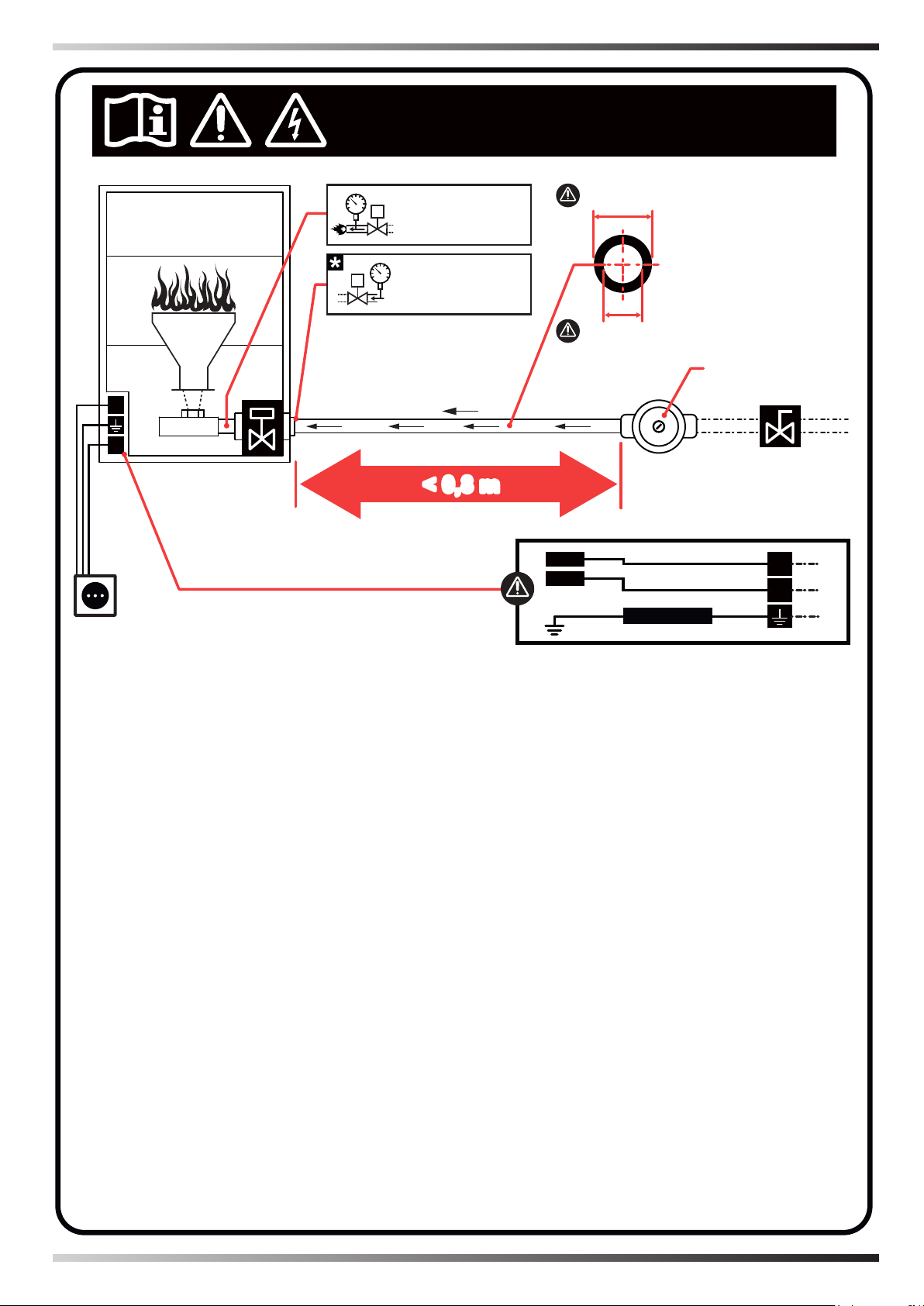
►en - STRICTLY COMPLY WITH ALL THE INDICATIONS IN THIS LABEL IN ORDER TO OBTAIN THE CORRECT
OPERATION OF THE HEATER. - Only use professional and perfectly calibrated equipment to set up the heaters (pressure gauges with MAX resolution 1 mbar). - (*) The set-up must be performed when all heaters, connected to the same
gas supply line, are running (simultaneous use).
►it - SEGUIRE SCRUPOLOSAMENTE TUTTE LE INDICAZIONI RIPORTATE IN QUESTA ETICHETTA, AL FINE DI
OTTENERE IL CORRETTO FUNZIONAMENTO DEL RISCALDATORE. - Per il settaggio dei riscaldatori usare solo
attrezzatura professionale e perfettamente tarata (manometri con risoluzione MAX. 1 mbar). - (*) Il settaggio va eseguito quando tutti i riscaldatori, connessi alla stessa linea di alimentazione gas, sono in funzione (uso simultaneo).
►de - UM DAS HEIZGERÄT ORDNUNGSGEMÄSS ZU BETREIBEN, ALLE AUF DIESEM ETIKETT AUFGEFÜHRTEN ANLEITUNGEN BEFOLGEN. - Für die Einstellung der Heizgeräte nur eine professionelle und einwandfrei kalibrierte Ausrüstung verwenden (Manometer mit MAX. Auflösung 1 mbar). - (*) Die Einstellung darf erst vorgenommen
werden, wenn alle an derselben Gasversorgungsleitung angeschlossenen Heizgeräte in Betrieb sind (gleichzeitige
Verwendung).
►es - SIGA ESCRUPULOSAMENTE TODAS LAS INDICACIONES CONTENIDAS EN ESTA ETIQUETA PARA
OBTENER EL CORRECTO FUNCIONAMIENTO DEL CALEFACTOR. - Para regular los calefactores, utilice solo un
equipo profesional y correctamente calibrado (manómetros con resolución MÁX. de 1 mbares). - (*) La regulación
deberá realizarse cuando todos los calefactores, conectados a la misma línea de alimentación de gas, estén en funcionamiento (uso simultáneo).
►fr - SUIVRE SCRUPULEUSEMENT TOUTES LES INDICATIONS REPORTÉES SUR CETTE ÉTIQUETTE, AFIN
D’OBTENIR LE FONCTIONNEMENT APPROPRIÉ DE L’APPAREIL DE CHAUFFAGE. - Pour le réglage des appareils de chauffage, n’utiliser que du matériel professionnel et parfaitement étalonné (manomètres à résolution MAX. 1
mbar). - (*) Le réglage doit être effectué lorsque tous les appareils de chauffage, connectés à la même conduite d'alimentation en gaz, fonctionnent (utilisation simultanée).
►ru - ДЛЯ ПРАВИЛЬНОЙ РАБОТЫ ОБОГРЕВАТЕЛЯ СТРОГО СЛЕДОВАТЬ ВСЕМ УКАЗАНИЯМ, ПРИВЕДЕН
НЫМ НА ЭТИКЕТКЕ. - Для настройки обогревателей пользоваться только профессиональными и правильно т
арированными приборами (манометры с разрешением МАКС. 1 мбар). - (*) Настройка должна выполняться. ко
гда все обогреватели, подсоединенные к одной линии подачи газ, находятся в работе (одновременное исполь
зование).
►zh - 严格遵守本标签内的一切说明,从而实现加热器的正确运行。- 为了设置加热器,只能使用精确校准的专业设
备(最大分辨率为1 mbar的压力表)。- (*) 当连接到同一天然气供应线的所有加热器都在运行时(同时使用),必须执
行此设置。
Page 3

Vers. CE
TECHNICAL DATA - DATI TECNICI - TECHNISCHE DATEN - DATOS TÉC-
NICOS - DONNÉES TECHNIQUES - TECHNISCHE GEGEVENS - DADOS
TÉCNICOS - TEKNISKE DATA - TEKNISET TIEDOT - TEKNISKE DATA
- TEKNISKA DATA - DANE TECHNICZNE - ТЕХНИЧЕСКИЕ ДАННЫЕ -
TECHNICKÉ ÚDAJE - MŰSZAKI ADATOK - TEHNIČNI PODATKI - TEKNİK
VERİLER - TEHNIČKI PODACI - TECHNINIAI DUOMENYS - TEHNISKIE
DATI - TEHNILISED ANDMED - DATE TEHNICE - TECHNICKÉ ÚDAJE -
ТЕХНИЧЕСКИ ДАННИ - ТЕХНІЧНІ ДАНІ - TEHNIČKI PODACI - ΤΕΧΝΙΚΑ
ΔΕΔΟΜΕΝΑ - 技术参数
3P
CH-
FR-
ES-
BE-
BE-CH-ES-
FR-GB-IR-IT-
DE-NL
GB-IR-
PT
I
3P
I
PT-IE
3+
I
3B/P
I
AT-CH-DE PL
SI-HR-LT-MK-
DK-FI-NL-NO-
SE-AL-BG-CZ-
SK-TR-RO-MT-
CF 75
HU BE DE FR PL NL
AL-BG-CZ-SI-HR-
AT-CH-DK-CY-EE-
LT-MK-SK-TR-RO-
FI-IE-IT-SE-NO-GB-
CY-EE-HU
PT-ES
3B/P
I
3B/P
I
2L
I
2E
I
2Er
- I
2Esi
I
2ELL
I
2E(H)B
I
2H
I
2H
I
G 20 G 20 G 20 G 20 G 25 G 20 / G 25 G 20 G 25 G 30 / G 31 G 30 / G 31 G 30 / G 31 G 30 + G 31 G 31 G 31
7 9 20 25
10 5
75 75
7,7 9,2 2,3 2,3 2,3 2,3 3,1 3,1
A2 A2
2.100 2.100
TEMPERATURE LIMIT: -20°C ÷ +40°C
~220-240 V 50 Hz 2,8 A ~220-240 V 50 Hz 2,8 A
20 25 20 20 20 / 25 20 25 28 - 30 50 37 28 - 30 / 37 37 50
17 18 17 17 17 17 20 25 42,5 25 25 25 42,5
25 33 25 25 30 25 30 35 57,5 45 45 45 57,5
ATTENTION: Pin: MAX 60 mbar
CAT.
GAS
[mbar]
[mbar]
[mbar]
P min.
P max.
[mbar]
[mm]
NOZZLE ⌀
/h]
3
[kW]
[m
GAS CONS.
Qn
/h]
3
[m
[V / Hz / A]
FAN
POWER SUPPLY
CATEGORY
Page 4
Vers. NO CE
TECHNICAL DATA - DATI TECNICI - TECHNISCHE DATEN - DATOS TÉC-
NICOS - DONNÉES TECHNIQUES - TECHNISCHE GEGEVENS - DADOS
TÉCNICOS - TEKNISKE DATA - TEKNISET TIEDOT - TEKNISKE DATA
- TEKNISKA DATA - DANE TECHNICZNE - ТЕХНИЧЕСКИЕ ДАННЫЕ -
TECHNICKÉ ÚDAJE - MŰSZAKI ADATOK - TEHNIČNI PODATKI - TEKNİK
VERİLER - TEHNIČKI PODACI - TECHNINIAI DUOMENYS - TEHNISKIE
DATI - TEHNILISED ANDMED - DATE TEHNICE - TECHNICKÉ ÚDAJE -
ТЕХНИЧЕСКИ ДАННИ - ТЕХНІЧНІ ДАНІ - TEHNIČKI PODACI - ΤΕΧΝΙΚΑ
ΔΕΔΟΜΕΝΑ - 技术参数
3P
I
3B/P
I
CF 75A
2L
I
2E
I
2H
I
G 20 G 25 G 30 / G 31 G 31
20-55 30-55
[mbar]
10 5
75 75
7 9 20 25
[mbar]
[mm]
[kW]
7,7 9,2 2,3 3,1
/h]
3
[m
A2 A2
2.100 2.100
~220-240 V 50 Hz 2,8 A ~220-240 V 50 Hz 2,8 A
[V / Hz / A]
/h]
3
[m
TEMPERATURE LIMIT: -20°C ÷ +40°C
ATTENTION: Pin: MAX 60 mbar
CAT.
NOZZLE ⌀
GAS
GAS CONS.
Qn
POWER SUPPLY
FAN
CATEGORY
Page 5
PICTURES - FIGURE - ABBILDUNGEN - FIGURAS - FIGURES - FIGUREN
1
4
5
3
6
>50cm
50÷200cm
>60cm
>60cm
>50cm
>300cm
>60cm
17cm
28cm
46cm
72cm
23cm
78cm
33cm
2
>50cm
- FIGURAS - FIGURER - KUVAT - FIGURER - FIGURER - ILUSTRACJE
- ИЛЛЮСТРАЦИИ - OBRÁZKY - ÁBRÁK - SLIKE - ŞEKİLLER - SLIKE -
ILIUSTRACIJOS - ATTĒLI - JOONISED - IMAGINI - OBRÁZKY - СХЕМИ -
МАЛЮНКИ - SLIKE - ΕΙΚΟΝΕΣ - 图示
Page 6
PICTURES - FIGURE - ABBILDUNGEN - FIGURAS - FIGURES - FIGUREN
7
10
11
8
9
Vers.
CE
Vers.
NO CE
- FIGURAS - FIGURER - KUVAT - FIGURER - FIGURER - ILUSTRACJE
- ИЛЛЮСТРАЦИИ - OBRÁZKY - ÁBRÁK - SLIKE - ŞEKİLLER - SLIKE -
ILIUSTRACIJOS - ATTĒLI - JOONISED - IMAGINI - OBRÁZKY - СХЕМИ -
МАЛЮНКИ - SLIKE - ΕΙΚΟΝΕΣ - 图示
Page 7
PICTURES - FIGURE - ABBILDUNGEN - FIGURAS - FIGURES - FIGUREN
12
13
15
14
Vers.
CE
Vers.
NO CE
- FIGURAS - FIGURER - KUVAT - FIGURER - FIGURER - ILUSTRACJE
- ИЛЛЮСТРАЦИИ - OBRÁZKY - ÁBRÁK - SLIKE - ŞEKİLLER - SLIKE -
ILIUSTRACIJOS - ATTĒLI - JOONISED - IMAGINI - OBRÁZKY - СХЕМИ -
МАЛЮНКИ - SLIKE - ΕΙΚΟΝΕΣ - 图示
Page 8
PICTURES - FIGURE - ABBILDUNGEN - FIGURAS - FIGURES - FIGUREN
16
18
17
Vers.
CE
Vers.
NO CE
Vers.
CE
Vers.
NO CE
Vers.
CE
Vers.
NO CE
- FIGURAS - FIGURER - KUVAT - FIGURER - FIGURER - ILUSTRACJE
- ИЛЛЮСТРАЦИИ - OBRÁZKY - ÁBRÁK - SLIKE - ŞEKİLLER - SLIKE -
ILIUSTRACIJOS - ATTĒLI - JOONISED - IMAGINI - OBRÁZKY - СХЕМИ -
МАЛЮНКИ - SLIKE - ΕΙΚΟΝΕΣ - 图示
Page 9
PICTURES - FIGURE - ABBILDUNGEN - FIGURAS - FIGURES - FIGUREN
19 20
21
22
- FIGURAS - FIGURER - KUVAT - FIGURER - FIGURER - ILUSTRACJE
- ИЛЛЮСТРАЦИИ - OBRÁZKY - ÁBRÁK - SLIKE - ŞEKİLLER - SLIKE -
ILIUSTRACIJOS - ATTĒLI - JOONISED - IMAGINI - OBRÁZKY - СХЕМИ -
МАЛЮНКИ - SLIKE - ΕΙΚΟΝΕΣ - 图示
Page 10

PICTURES - FIGURE - ABBILDUNGEN - FIGURAS - FIGURES - FIGUREN
24
27
25
26
23
- FIGURAS - FIGURER - KUVAT - FIGURER - FIGURER - ILUSTRACJE
- ИЛЛЮСТРАЦИИ - OBRÁZKY - ÁBRÁK - SLIKE - ŞEKİLLER - SLIKE -
ILIUSTRACIJOS - ATTĒLI - JOONISED - IMAGINI - OBRÁZKY - СХЕМИ -
МАЛЮНКИ - SLIKE - ΕΙΚΟΝΕΣ - 图示
Page 11

en
1... DESCRIPTION
it
2... WARNINGS
de
PARAGRAPH SUMMARY
3... UNPACKING
es
4... HANDLING
fr
5... POSITIONING
6... CONNECTION TO THE GAS MAINS
nl
7... CONNECTION TO THE ELECTRICITY MAINS
pt
8... CONVERSION TO ANOTHER TYPE OF GAS
da
9... TYPE OF FUEL
10... SWITCH-ON
11... FAULT LIGHT
no
12... SWITCH-OFF
sv
13... CONNECTING THE REMOTE ROOM THERMOSTAT
14... CLEANING THE HEATER
pl
15... PUTTING THE HEATER OUT OF SERVICE
ru
16... OPTIONAL ITEMS
cs
17... TROUBLESHOOTING
hu
sl
IMPORTANT: READ AND UNDERSTAND THIS OPERATIONAL
MANUAL PRIOR TO ASSEMBLING, STARTING UP OR CONDUCTING
tr
MAINTENANCE ON THIS HEATER. USING THE HEATER
hr
lv
INCORRECTLY CAN CAUSE SERIOUS INJURY. KEEP THIS MANUAL
lt
FOR FURTHER REFERENCE.
►►1.DESCRIPTION
et
This gas heater is a product that releases
ro
heat into the air of the room it operates in
by either using natural gas or liquid pro
sk
pane gas. It is intended for xed installa-
bg
tion indoors or outdoors following an assessment of the rooms and by using the
uk
designated
bs
kits. The air drawn in by a centrifugal
ventilation system is conveyed towards
el
the burner, which controls combustion.
zh
This way the air heats up and is introduced into the room again. This direct
combustion system mixes the combustion by-products with the air drawn in and
releases them into the environment at a
later stage. Given that the volume of air
treated is greater than the actual combus-
tion needs, hot air comes out with a low
concentration of carbon dioxide.
This system means one can create a
-
heater with:
•Maximum thermal eciency.
•Low thermal inertia.
•Small size and reduced weight.
•Simple design.
•Maximum reliability.
With a specic function, one can activate
just activate the ventilation unit, thereby
moving around the air.
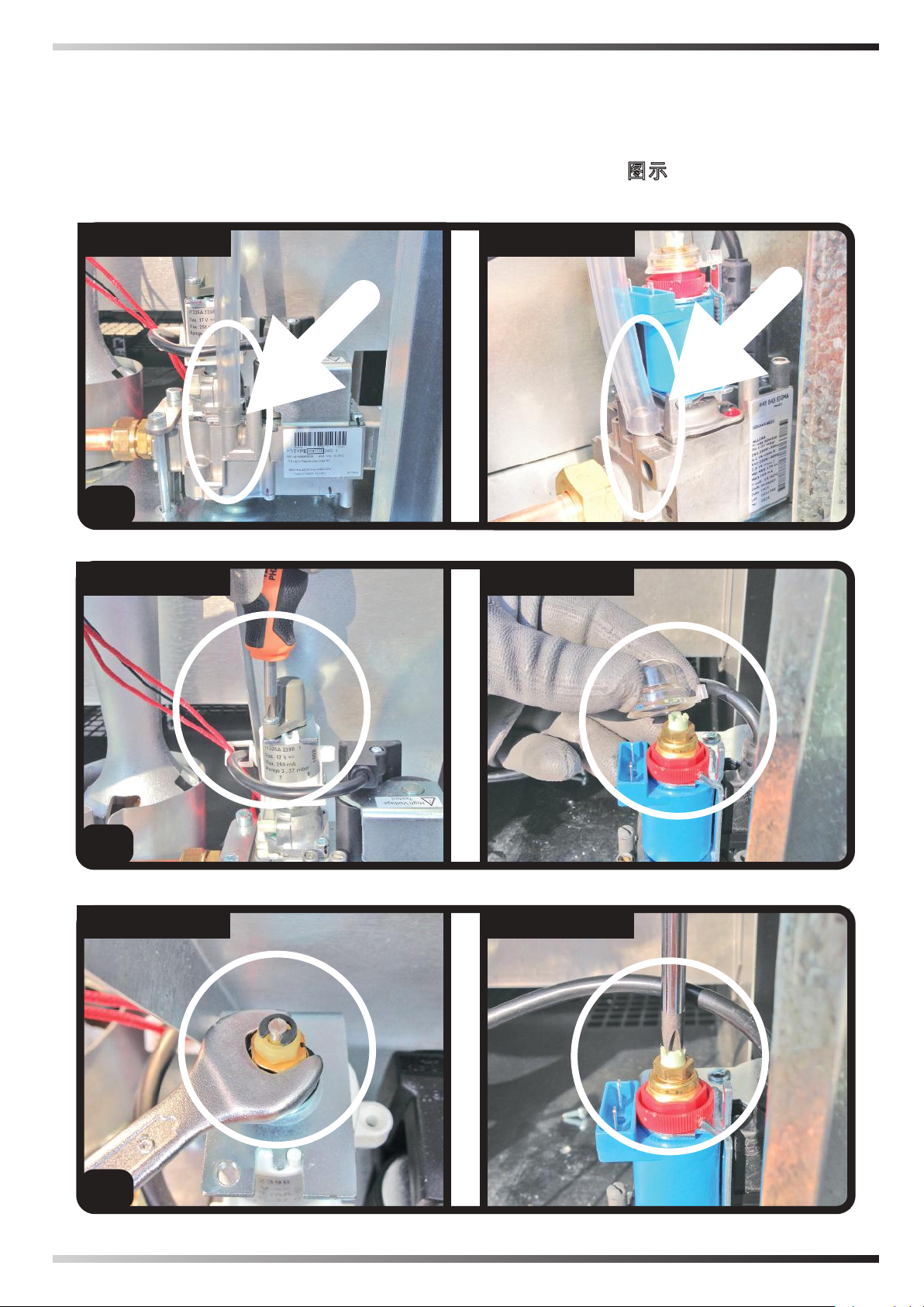
This product can be identied via the data
plate applied on the heater, which permanently reports the gaseous combustible
materials that should be used, specications and all the technical information of
the heater. If the data plate or the instruc-
Page 12

tion manual is damaged or lost, please
request a duplicate from the authorised
technical support centre.
►►2.WARNINGS
••2.1.
IMPORTANT: The manufacturer is responsible for compliance
of the product with laws, directives or
building standards in force when the
product is marketed. The technician
authorised by the technical support
centre and the user are responsible for
learning about and complying with the
regulations and standards relating to
the design of the system, installation,
operation and maintenance.
••2.2.
IMPORTANT: The manufacturer cannot be held liable for failure to
comply with the instructions contained
in the following instruction manual, for
consequences to any manoeuvre per-
formed and not specically envisaged
or for any translations that may result
in erroneous interpretations.
••2.3.
IMPORTANT: This instruction
manual is an integral part of the heater
and therefore must be carefully preserved. It must always remain with the
appliance, even if transferred to another owner or user. If the data plate or the
instruction manual is damaged or lost,
please request a duplicate from the authorised technical assistance centre.
••2.4.
IMPORTANT: This heater is
not suitable for use by persons (including children) with reduced physical,
sensory or mental capacities or with
lack of experience or knowledge unless supervised by a person responsible for their safety. Children must be
supervised to make sure they do not
play with the heater. Keep animals at a
safe distance from the heater.
••2.5.
IMPORTANT: Improper use of
this heater can cause damage, injuries,
en
it
burns, explosions, electric shock or
endanger life. The rst symptoms of
de
suocation by carbon monoxide are
similar to those of u with headache,
es
fr
light-headedness and/or nausea.
These symptoms could be caused by
the faulty functioning of the heater.
nl
pt
IF THESE SYMPTOMS OCCUR, GO
OUTDOORS IMMEDIATELY and have
the heater repaired by an authorised
technical support centre.
••2.6.
IMPORTANT: Any contractual
and extra-contractual liability of the
manufacturer for injury caused to persons, animals or damage caused to
da
no
sv
pl
ru
property due to incorrect installation,
adjustment and maintenance or improper use is excluded.
••2.7.
IMPORTANT: References to
cs
hu
sl
laws, regulations, directives and technical rules that may be mentioned in
this instruction manual are intended
tr
hr
for information purposes only and
are believed to be correct at the time
of printing of the manual itself. The
lt
lv
entry into force of new regulations or
amendments to existing ones will not
constitute grounds for obligation for
the manufacturer towards third par
et
ro
-
sk
ties.
••2.8.
IMPORTANT: The heater must
be positioned and secured by quali-
ed personnel. The connection to the
bg
uk
bs
gas and electricity mains must be carried out by an authorised technician.
When the work is completed, the lat-
el
zh
ter will give the owner the declaration
of conformity for the installation performed to a professional standard, i.e.
in compliance with current standards
and instructions given by the manufacturer in this instruction manual. Work
involving access to dangerous areas
Page 13

(maintenance, repairs, etc.) must be
en
carried out by the authorised technical
it
support centre to prevent any risks.
de
••2.9.
not have gas regulators or pipes to
es
IMPORTANT: The heater does
connect it to the mains. Therefore,
fr
you will need to contact an authorised
nl
technician for the installation.
••2.10.
pt
IMPORTANT: The heater is
supplied with a specic gas setting.
da
Any kind of change and adjustment
must be performed by an authorised
technician or by the authorised tech
no
nical support centre. IF ANY CHANG-
sv
ES AND ADJUSTMENTS ARE PERFORMED, YOU WILL NEED TO FILL
pl
IN THE NEUTRAL DATA PLATE SUP-
ru
PLIED WITH THE HEATER.
cs
••2.11.
the supply gas pressure values must
hu
IMPORTANT: The settings of
be checked by an authorised techni
sl
cian.
tr
••2.12.
be installed exclusively in accordance
hr
IMPORTANT: The heater must
with the instructions contained in this
lt
instruction manual to prevent any po-
tential res.
lv
••2.13.
et
IMPORTANT: Do not use to
heat homes or residential buildings;
ro
for use in public buildings, refer to national regulations.
sk
••2.14.For correct use of the heater
bg
and for preservation of the fuel, follow
all local regulations and the Standard
uk
in force.
bs
••2.15.If the heater is installed in-
el
doors, it needs an adequate supply of
fresh air. It must therefore be used in
zh
rooms with a guaranteed and continuous supply of fresh air. National Standards in force are valid for installation
and assessment of the supply of fresh
air, including the Technical Standards
and the provisions regarding accident-
prevention and the prevention of res.
••2.16.The appliance must only be
used as a hot air heater (heating mode)
or fan (ventilation mode). Follow these
instructions scrupulously.
••2.17.Only use fuel, gas pressure val
ues, voltage and electrical frequency
clearly specied in the data plate applied on the heater.
••2.18.Make sure the heater is only
connected to suitable mains with a differential switch and suitable earthing.
••2.19.It is prohibited to use the heater
-
in basements and rooms below ground
level.
••2.20.The heater must not be used in
places where explosive dust, fumes,
gases, fuels, solvents, paint, etc. are
present.
••2.21.Whenever the heater is used
near tarpaulins, awnings or similar
covering materials, additional protec-
-
tion is recommended, such as reproong. Make sure the hot parts of
the generator are kept at a suitable distance from inammable materials (fabric, paper, wood, etc.) or thermolabile
materials (including the power supply
cable). In any case, the distance should
never be less than 3 m.
••2.22.The air vent (lower side) and/
or the air outlet vent (front side) must
not be totally or partially obstructed
for any reason You can use air ducting from or to the heater. The only authorised ducting is the one supplied as
optional items by the manufacturer.
••2.23.If the heater does not switch
on or switch-on is anomalous, please
see the relative section (Paragraph on
“Troubleshooting”).
••2.24.The heater must never be
moved, handled or subjected to any
maintenance interventions when running.
••2.25.Do not open the side inspection
doors and carry out work inside when
Page 14

the heater is in operation or when it is
powered on and not in operation.
••2.26.If you smell gas, switch the
heater o immediately, stop the gas
supply, disconnect the heater from the
electricity mains, provide fresh air by
opening doors and windows and then
contact the authorised technical sup
-
port centre.
••2.27.When the heater is controlled
by a remote room thermostat (optional
item), the heater can switch back on at
any time when the temperature drops
below the set threshold.
••2.28.If the heater is not used for an
extended period of time, we recommend contacting the authorised technical support centre to put it back in
operation.
••2.29.The heater must only be tted
with original accessories. The manufacturer is not responsible for any
damage deriving from improper user
of the heater and use of non-original
materials and accessories.
••2.30.Do not modify or tamper with the
heater as this may lead to hazardous
situations. The manufacturer will not
be held liable for any damage caused.
••2.31.Do not place any objects on the
heater.
••2.32.Do not insert objects through
the heater's grids.
••2.33.Do not touch the air outlet grid,
as during normal operation it can reach
high temperatures, which may cause
serious injury.
••2.34.Do not use adapters, multi
socket outlets and extensions to connect the heater to the electricity mains.
••2.35.Do not perform any cleaning
and maintenance before plugging out
the heater from the electricity mains
and fuel supply.
••2.36.Ask the technical support service to check that the heater is work-
ing properly at least once a year and/
or as required.
►►3.UNPACKING
DO NOT THROW AWAY THE MATERI
ALS (CARDBOARD, PLASTIC PACKAGING, BAGS, ETC.) OR GIVE THEM
TO CHILDREN OR LEAVE THEM WITHIN THEIR REACH, AS THEY MAY REPRESENT A HAZARD.
Remove all packaging material used to
deliver the heater and dispose of it in compliance with current standards. Check for
any damage undergone during transport.
If the heater looks damaged, inform the
dealer immediately.
►►4.HANDLING
THE HEATER MUST BE HANDLED BY
QUALIFIED PERSONNEL BY USING
SUITABLE DEVICES AND INSTRUMENTS, IN ACCORDANCE WITH NATIONAL REGULATIONS AND CURRENT STANDARDS.
►4.1.HANDLING THE HEATER WITH
THE PACKAGING
It can be lifted with a forklift truck by positioning the supports under the lower base
of the packaging.
►4.2.HANDLING THE HEATER WITHOUT THE PACKAGING
It can be lifted with the forklift truck by
positioning the supports underneath the
lower base of the packaging or by using
chains and suspension hooks.
en
it
de
es
fr
nl
pt
da
no
sv
pl
ru
cs
hu
sl
tr
hr
lt
lv
et
ro
sk
bg
uk
bs
el
zh
Page 15

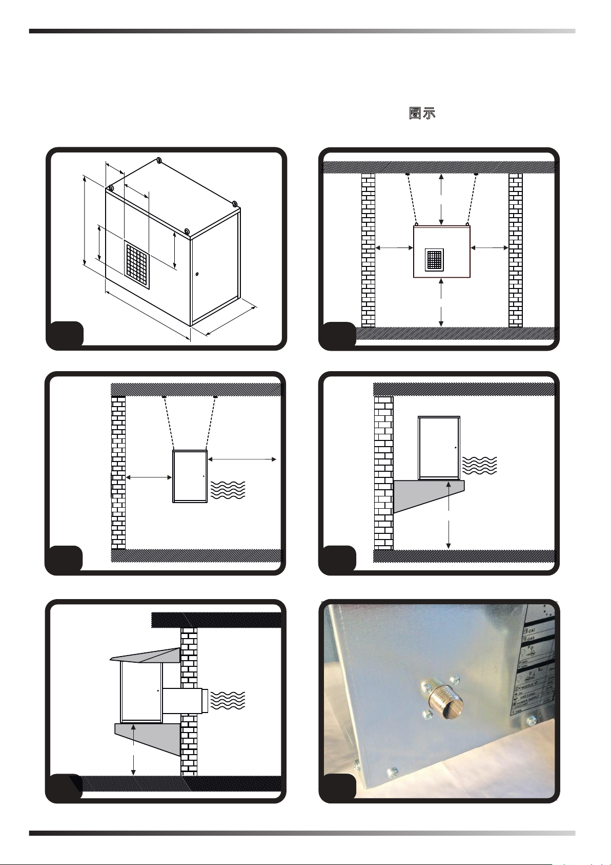
►►5.POSITIONING (Fig. 1)
en
READ THE WARNINGS CAREFULLY
it
AND FOLLOW THE RECOMMENDA
de
TIONS CONTAINED IN THIS INSTRUCTION MANUAL BEFORE AND DURING
es
INSTALLATION.
fr
THE HEATER MUST BE POSITIONED
nl
BY QUALIFIED PERSONNEL BY US-
pt
ING SUITABLE DEVICES AND INSTRU-
da
MENTS, IN ACCORDANCE WITH NATIONAL REGULATIONS AND CUR-
RENT STANDARDS.
no
••IMPORTANT: Do not power on the
sv
heater before the installation has been
pl
completed in order to prevent damage to
property and/or injury to persons.
ru
cs
This heater is designed to be installed
hu
indoors or outside a building. It can be
installed outdoors only with the desig-
sl
nated original kit (Paragraph on “Option-
tr
al items”). Before positioning the heater,
make sure you have identied the correct
hr
position for the installation, away from
lt
ammable materials, with the right dis-
lv
tance from the ground so as to not obstruct, not even in part, the air intake grid
et
at the bottom of the heater. This is why
ro
you need to check the grid is at the right
distance from the ground or materials
sk
that can be drawn in. The place where
bg
it is installed must be easy to access to
make normal maintenance and inspec-
uk
tion operations easier. The heater must
bs
be secured safely and permanently to the
el
structure. Do not attach additional weight
to the heater.
zh
►5.1.INDOOR INSTALLATION ON THE
CEILING (Fig. 2-3)
Each chain and suspension hook must
withstand a minimum weight of 100 kg.
The surface on which the product is attached (for instance the ceiling) must
withstand a minimum weight of 200 kg.
There must be a positive angle between
-
the chains and a value that can ensure
stability, in order to prevent dangerous os
-
cillations.
►5.2.INSTALLATION ON THE WALL
(Fig. 4)
Each wall plug must withstand a minimum
load of 200 kg. The masonry structure
must withstand the weight of the heater
placed on the brackets.
►5.3.OUTDOOR INSTALLATION ON
THE WALL (Fig. 5)
Each wall plug must withstand a minimum
load of 200 kg. The masonry structure
must withstand the weight of the heater
placed on the brackets. The air intake and
booster ducts must follow the specications described in the original kit (Paragraph on “Optional items”).
►►6.CONNECTION TO THE GAS
MAINS (Fig. 6)
READ THE WARNINGS CAREFULLY
AND FOLLOW THE RECOMMENDATIONS CONTAINED IN THIS INSTRUCTION MANUAL BEFORE AND DURING
INSTALLATION.
THE GAS SUPPLY LINE AND CONNECTION MUST BE CARRIED OUT
BY AN QUALIFIED TECHNICIAN BY
USING SUITABLE DEVICES AND INSTRUMENTS, IN ACCORDANCE WITH
NATIONAL REGULATIONS AND CURRENT STANDARDS.
The heater is designed to operate with different kinds of gas, but it is supplied with
specic factory settings (see data plate
applied on the heater). Never exceed the
maximum supply pressure values report-
Page 16

ed on the data plate in order to prevent
serious damage to the heater.
The gas regulator must be installed out
side the building that needs to be heated
and must guarantee a supply at a pressure in line with national regulations and
the heater's technical specications. The
regulator can be installed indoors only in
a suitably ventilated area. National regulations will help you identify the correct installation.
Connect the heater to the gas mains by
placing the utmost attention on the kind of
connection (ISO 7-1:1994 thread suitable
for sealing on a conical thread). The gas
pipes must have a suitable size, position
and anchoring. During the rst start-up,
use an approved device to check for any
leaks due to incorrect tightening or damage to the gas supply circuit.
necessary to verify its perfect connection
of the grounding.
We recommend using a 1,5 mm² (AWG
16) H07 type cable with length not exceed
ing 5 m. After making sure the heater is
disconnected from the gas mains, open
the electrical panel (Fig. 7), insert the supply cable in the cable gland (Fig. 8) and
connect the cables to the suitable terminal
board (Fig. 9). Upon completing connection restore the electrical panel.
►►8.CONVERSION TO ANOTHER
TYPE OF GAS
READ THE WARNINGS CAREFULLY
AND FOLLOW THE RECOMMENDATIONS CONTAINED IN THIS INSTRUCTION MANUAL BEFORE AND DURING
INSTALLATION.
en
it
de
es
fr
nl
pt
da
no
sv
pl
ru
cs
hu
sl
►►7. CONNECTION TO THE
ELECTRICITY MAINS
READ THE WARNINGS CAREFULLY
AND FOLLOW THE RECOMMENDA
TIONS CONTAINED IN THIS INSTRUCTION MANUAL BEFORE AND DURING
INSTALLATION.
THE POWER SUPPLY LINE AND CON
NECTION MUST BE CARRIED OUT
BY AN QUALIFIED TECHNICIAN BY
USING SUITABLE DEVICES AND IN
STRUMENTS, IN ACCORDANCE WITH
NATIONAL REGULATIONS AND CUR
RENT STANDARDS.
••IMPORTANT: The heater must be con
nected to a suitable dierential and magnetothermal control system that ensures
the power supply is disconnected in the
event of any anomalies of the heater. For
the correct functioning of the heater, it is
THE CONVERSION TO ANOTHER TYPE
OF GAS MUST BE CARRIED OUT BY
AN AUTHORISED TECHNICIAN OR BY
THE AUTHORISED TECHNICAL SUPPORT CENTRE BY USING SUITABLE
DEVICES AND INSTRUMENTS, IN ACCORDANCE WITH NATIONAL REGULATIONS AND CURRENT STANDARDS.
••IMPORTANT: The conversion must be
carried out after closing and disconnecting
the heater from the gas and electricity
mains (Fig. 24).
The types of gas compatible with this
kind of heater are briey reported in the
gas type label. The gas setting, before
the conversion of the heater, can be
identied based on the data plate applied
on the heater. When the gas conversion
has been completed, permanently report
the parameters of the new setting on the
neutral data plate supplied and then apply
tr
hr
lt
lv
et
ro
sk
bg
uk
bs
el
zh
Page 17

it on the heater. Here below are the steps
en
for the conversion to another combustible
it
gas:
de
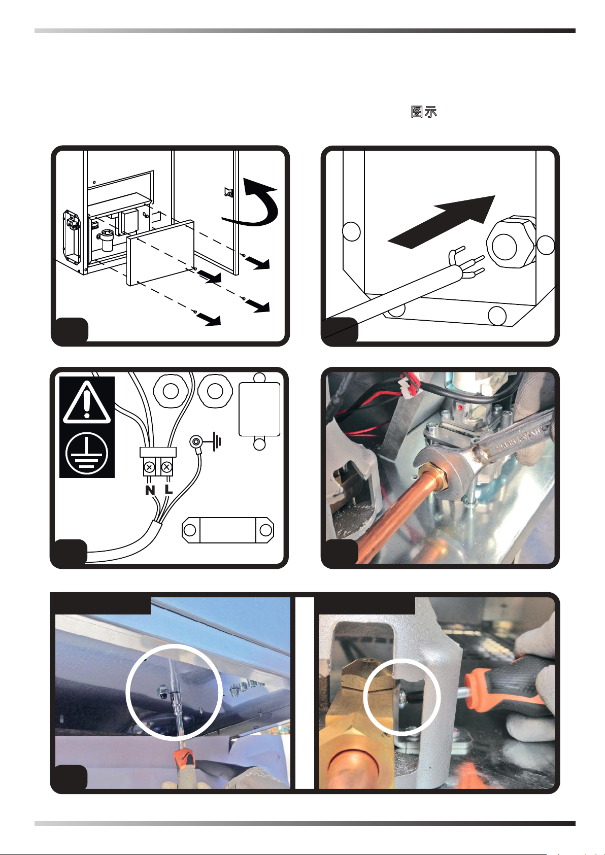
►8.1.REMOVE THE VALVE AND
es
NOZZLE SUPPORT CONNECTION
fr
PIPE, REMOVE THE NOZZLE
SUPPORT, REMOVE THE NOZZLE
nl
PROCEDURE:
pt
•8.1.1.Remove the conical tip tightening
da
ring on the valve side (Fig. 10).
•8.1.2.Remove the nozzle support
fastening screw (Fig. 11).
no
•8.1.3.Take out the nozzle support and
the gas pipe section (Fig. 12).
sv
•8.1.4.Remove the gas nozzle (Fig. 13).
pl
CAUTION: CAREFULLY KEEP ALL THE
COMPONENTS (GASKETS, CONICAL
ru
TIPS, ETC.).
cs
hu
►8.2.CHOOSING THE NOZZLE
Choosing the right nozzle:
sl
LPG nozzle = 5 mm diameter
tr
G20 nozzle = 10 mm diameter
G25 nozzle = 10 mm diameter
hr
lt
►8.3.PLACE BACK THE VALVE AND
lv
NOZZLE SUPPORT CONNECTION
PIPE, PLACE BACK THE NOZZLE
et
SUPPORT, PLACE BACK THE
ro
NOZZLE
PROCEDURE:
sk
•8.3.1.Attach the nozzle to the nozzle
bg
support and ensure the connection is
airtight. Make sure the nozzle you choose
uk
is suitable for the desired conversion (Fig.
bs
13).
el
•8.3.2.Insert the nozzle support with the
pipe underneath the burner and secure it
zh
to the base with the screw (Fig. 12-11).
•8.3.3.Tighten the conical tip tightening
tting to the gas valve (Fig. 10).
•8.3.4.Make sure the connections are
rmly attached.
CAUTION: IF USING G20-G25 GAS,
INSTALL THE AIR REDUCTION COLLAR
(Fig. 14). THIS COLLAR IS ONLY
REQUIRED FOR G20-G25 GAS TYPES.
►8.4.ADJUST THE OUTLET
PRESSURE FROM THE GAS VALVE
CAUTION: THE ADJUSTMENT MUST
BE CONDUCTED QUICKLY AND
ACCURATELY.
After assembling the duct onto the new
nozzle, you need to set the heater's
multipurpose gas valve at the right supply
pressure. The pressure must be adjusted
when the heater is in operation and the
gas supply is connected. Before starting
the adjustment, make sure the heater is
powered on with the right type of gas for
the nozzle installed.
PROCEDURE:
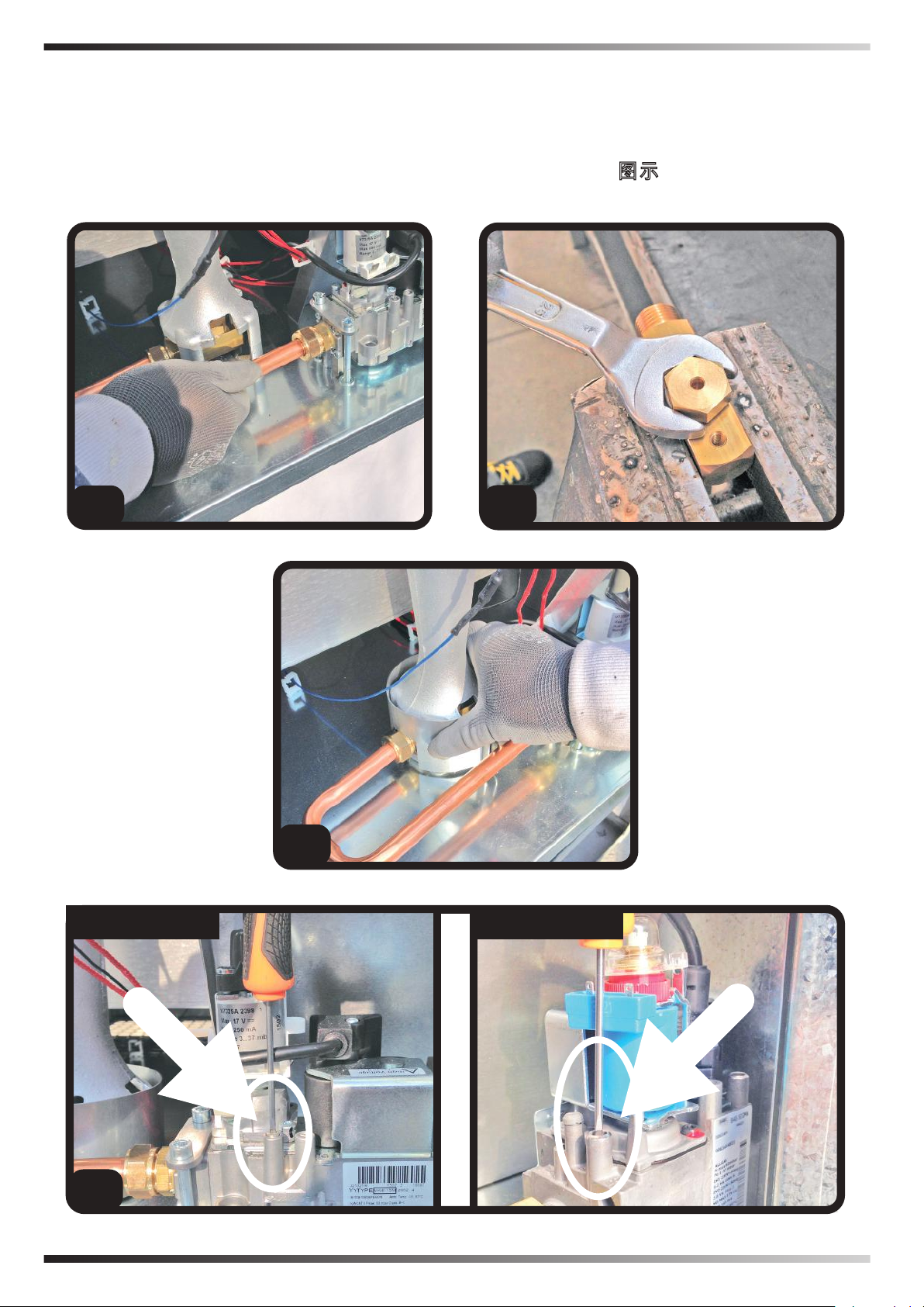
•8.4.1.Identify where the gas valve
outlet pressure is taken and remove the
tightening screw (Fig. 15).
•8.4.2.Connect a exible rubber pipe,
make sure it is rmly attached (Fig. 16).
Considering that the pressure values are
set to minimum values, use a dierential
manometer or, better still, a water tube
manometer.
•8.4.3.Remove the protective cover (Fig.
17) and identify the rotation screw used to
adjust the pressure on the gas valve.
•8.4.4.Prepare the specic tool to operate
on the adjustment pin.
•8.4.5.Turn on the heater and wait for a few
seconds while the prewash is conducted.
You can then open the gas and the ame
will come on. At this exact moment you
need to rotate the pin (Fig. 18) until the
required outlet pressure value is reached
(clockwise to increase it, anticlockwise to
reduce it). After adjusting the pressure,
we recommend repeating the ignition
cycle three times with the inspection
doors closed and by checking again the
outlet pressure of the gas valve. Before
Page 18

completing the gas conversion, you will
need to make sure the ttings and gas
pipe are rmly attached.
•8.4.6.When the gas conversion has
been completed, permanently report the
parameters of the new setting on the
neutral data plate supplied (Fig. 19) and
then apply it on the heater.
►►9.TYPE OF FUEL
ONLY USE GAS RELATING TO THE
CATEGORY REPORTED ON THE GAS
TYPE STICKER TO PREVENT SERI
OUS DAMAGE TO THE HEATER.
►►10.IGNITION (Instructions for
ignition, ventilation and heating)
(Fig. 20)
READ THE WARNINGS CAREFULLY
AND FOLLOW THE RECOMMENDATIONS CONTAINED IN THIS INSTRUCTION MANUAL WHEN USING THE
PRODUCT.
THE FIRST START-UP MUST BE CONDUCTED BY AN AUTHORISED TECHNICIAN OR BY THE AUTHORISED
TECHNICAL SUPPORT CENTRE.
••IMPORTANT: Before the rst ignition,
make sure there are no packaging residues or accessories inside the heater.
••IMPORTANT: Before turning on the product, make sure the heater is installed correctly (the gas connection, inlet pressure
and electrical connection must comply with
current regulations and match the values
declared on the data plate). Also ensure
there are no obstructions in the air circuit.
••IMPORTANT: During the rst start-up,
use an approved device to check for any
leaks due to incorrect tightening or damage to the gas supply circuit.
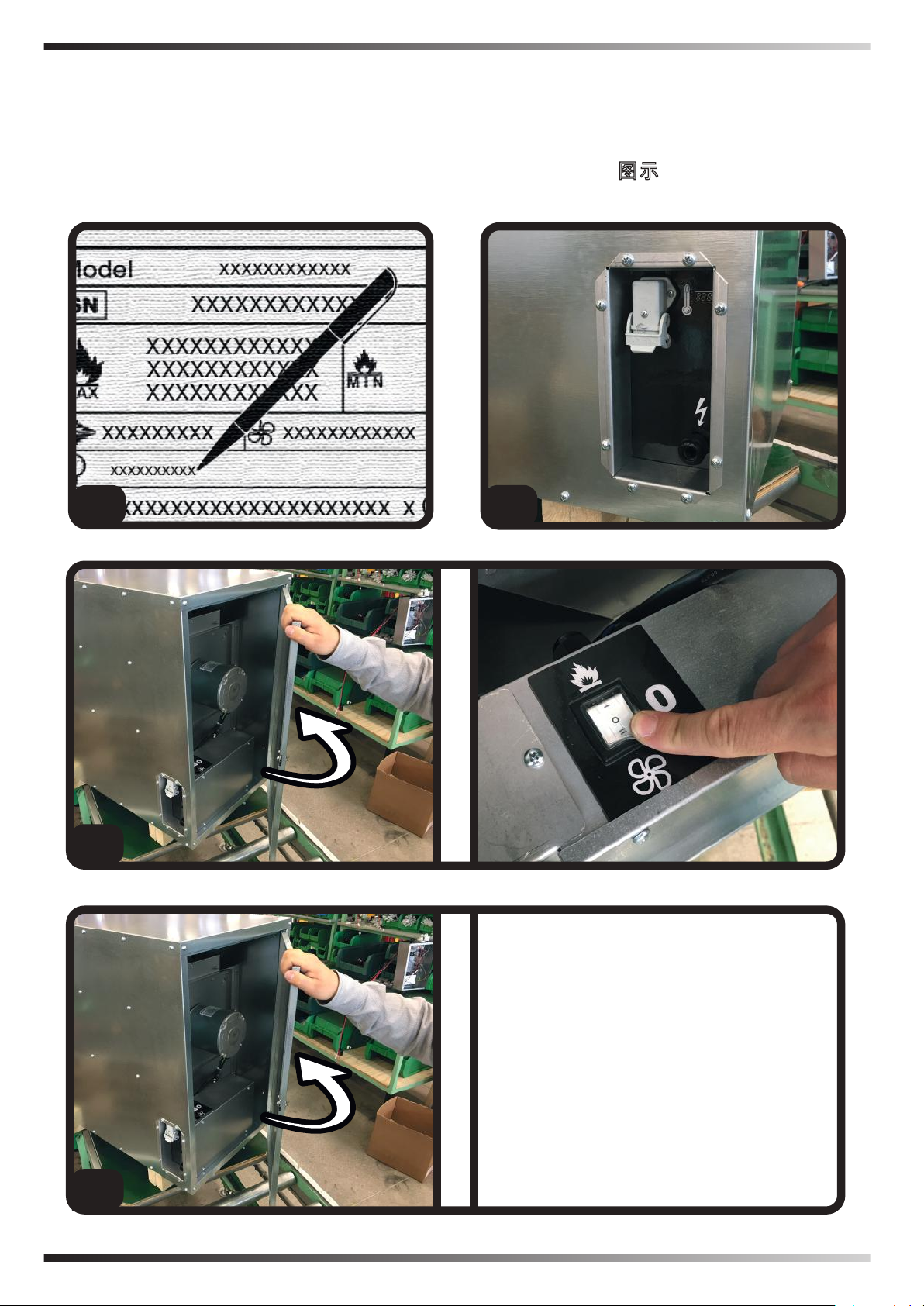
The heater can operate either in ventilation
en
or heating mode. To start the ventilating
mode, set the button to the “FAN” position
(Fig. 21). This way the heater only starts
the motor and keeps the gas circuit closed.
it
de
es
If you want to start the heating mode, set
the button to the “FLAME” position (Fig.
22). The heater opens the gas circuit and
fr
nl
starts the spark - thereby starting the combustion - only after activating just the fan
to ensure the prewash of the combustion
chamber for around 30 seconds.
pt
da
If the ignition fails more than 3 times, the
heater is blocked. To reset the heater, set
the start button to “O” (Fig. 23). A preven-
no
sv
tive analysis of potential causes is briey
reported in the anomalies table (Paragraph
on “Troubleshooting”).
pl
ru
CAUTION: IF THE IGNITION FAILS
MORE THAN THREE TIMES, THE REASON NEEDS TO THE CHECKED VIA
THE AUTHORISED TECHNICAL SUP-
cs
hu
sl
PORT CENTRE.
tr
hr
►►11.WARNING LIGHT
The heater is tted with a light to monitor
the heater's operation (Fig. 25):
lt
lv
et
•LIGHT OFF (normal condition): This
means the heater is o or working normally.
ro
sk
•LIGHT ON: This means the heater is
blocked.
►►12.TURNING OFF THE HEATER
To turn o the heater, set the button to the
bg
uk
bs
el
zh
“O” position (Fig. 23).
CAUTION: WHEN THE PUSHBUTTON
IS IN POSITION “O”, THE HEATER IS
OFF BUT IS STILL POWERED BY THE
MAINS POWER NETWORK. FOR MAINTENANCE, CLEANING OR OTHER IT IS
Page 19

REQUIRED TO COMPLETELY ISOLATE
en
THE HEATER FROM THE MAINS POW-
it
ER NETWORK (Fig. 24).
de
es
fr
►►13.CONNECTING THE REMOTE ROOM THERMOSTAT
nl
••IMPORTANT: When the heater is con-
pt
trolled by a remote room thermostat, the
da
heater can switch back on at any time
when the temperature drops below the
set threshold.
no
►►15.PUTTING THE HEATER
OUT OF SERVICE
If the heater is not used on the medium/
long term, disconnected it from the elec
tricity mains (Fig. 24) and protect it from
humidity and dust. When the heater is
used again, check the condition of the
power supply cable. If in doubt regard
ing its state, contact the technical support centre. In any case, have the heater
checked once a year.
To connect the remote room thermostat,
sv
remove the plug connected to the heater
pl
and connect the remote room thermostat
(optional item) (Fig. 26).
ru
cs
hu
►►14.CLEANING THE HEATER
sl
••IMPORTANT: Do not conduct any clean-
tr
ing unless the heater has rst been turned
o (Fig. 23) and disconnected from the
hr
mains (Fig. 24).
lt
lv
The only possible cleaning steps carried
out by the user are associated with the
et
heater's outer surfaces. Only use a damp,
ro
non-abrasive cloth to clean the outer
surface of the heater (do not use sponges
sk
with aggressive products or powder
bg
detergents). After cleaning the surface,
dry it thoroughly.
uk
CAUTION: IF THE HEATER NEEDS
bs
MORE THOROUGH CLEANING,
el
CONTACT THE AUTHORISED
TECHNICAL SUPPORT CENTRE.
zh
►►16.OPTIONAL ITEMS
•Outdoor assembly kit (recirculation or air
suction mode, depending on the external
damper position).
•Remote room thermostat.
•Air outlet opening diuser.
Page 20

►►17.TROUBLESHOOTING
en
FAULTS CAUSES SOLUTIONS
The heater
doesn't work
No voltage 1.Check the mains system
2.Check the electrical connections
3.Authorised technical support centre
Incorrect connection of
1.Connect the room thermostat correctly
the room thermostat
The heater
doesn't work in
heating mode
Tripped room
thermostat (optional
item)
Incorrect connection of
1.Set the room thermostat at a temperature
lower than the room thermostat
1.Connect the room thermostat correctly
the room thermostat
Room thermostat
1.Insert the cap properly in the socket
socket cap not
inserted properly
No gas supply 1.Check the gas system
2.Authorised technical support centre
Blocked heater 1.Reset the heater by setting the power
button to position “0”
2.Authorised technical support centre
Defective electronic
1.Authorised technical support centre
equipment
Incorrect heater setting 1.Authorised technical support centre
it
de
es
fr
nl
pt
da
no
sv
pl
ru
cs
hu
sl
tr
The ame
does not stay
on
The ame
turns o
during normal
operation
Defective electronic
1.Authorised technical support centre
equipment
Tripped room
thermostat (optional
1.Set the room thermostat at a temperature
lower than the room thermostat
item)
No gas supply 1.Check the gas system
2.Authorised technical support centre
No voltage 1.Check the mains system
2.Check the electrical connections
3.Authorised technical support centre
The heater overheats 1.Clean the air inlet (lower side) and reset
the manual security thermostat (Fig. 27)
2.The heater's limit operating temperatures
are too high
3.The air intake temperatures are too high
4.Extensive exposure to sun light
5.Authorised technical support centre
hr
lt
lv
et
ro
sk
bg
uk
bs
el
zh
Page 21

JT2
JT1
FUSE 4AF
J1
J2
J3
J4
J6
J5
230V
CA
ELECTRIC SYSTEM - IMPIANTO ELETTRICO - ELEKTRISCHE ANLAGE
- INSTALACIÓN ELÉCTRICA - INSTALLATION ELECTRIQUE - ELEKTRISCHE INSTALLATIE - SISTEMA ELÉTRICO - EL-ANLÆG - SÄHKÖLAIT-
TEISTO - ELEKTRISK ANLEGG - ELANORDNING - INSTALACJA
ELEKTRYCZNA - ЭЛЕКТРОПРОВОДКА - ELEKTRICKÉ ZAŘÍZENÍ - ELEKT-
ROMOS RENDSZER - ELEKTRIČNA NAPELJAVA - ELEKTRİK TESİSATI
- ELEKTRIČNI UREĐAJ - ELEKTROS SISTEMA - ELEKTRISKĀ SISTĒMA
- ELEKTRISÜSTEEM - INSTALAŢIA ELECTRICĂ - ELEKTRICKÉ ZARIADE
NIE - ЕЛЕКТРИЧЕСКА ИНСТАЛАЦИЯ - ЕЛЕКТРИЧНЕ ОБЛАДНАННЯ -
ELEKTRIČNI UREĐAJ - ΗΛΕΚΤΡΙΚΗ ΕΓΚΑΤΑΣΤΑΣΗ -
电路系统
-
Page 22

IN
M
EV
IG
R
TS
RL
CA
TA
FS
ION
L
N
Switch - Interruttore - Schalter - Interruptor - Interrupteur - Schakelaar - Interruptor - Afbryder Katkaisin - Bryter - Brytare - Włącznik - Включатель - Vypínač - Kapcsoló - Stikalo - Açma kapama
düğmesi - Prekidač - Jungiklis - Slēdzis - Lüliti - Întrerupător - Vypínač - Прекъсвач - Вимикач Prekidač - Διακόπτης - 开关
Motor - Motore - Motor - Motor - Moteur - Motor - Motor - Motor - Moottori - Motor - Motor - Silnik
- Двигатель - Motor - Motor - Motor - Motor - Motor - Variklis - Dzinējs - Mootor - Motor - Motor Двигател - Двигун - Motor - Κινητήρας - 电机
Solenoid valve - Elettrovalvola - Elektroventil - Electroválvula - Électrovalve - Elektroklep - Eletroválvula
- Magnetventil - Solenoidiventtiili - Magnetventil - Magnetventil - Zawór elektromagnetyczny Соленоид - Elektrický ventil - Mágnesszelep - Elektromagnetni ventil - Elektrovalf - Električni ventil Elektrinis vožtuvas - Elektrovārsts - Solenoidventiil - Electrovalvă - Elektrický ventil - Електроклапан
- Електроклапан - Električni ventil - Ηλεκτροβαλβίδα - 电磁阀
Igniter - Accenditore - Anzünder - Encendedor - Allumeur - Ontsteker - Acendedor - Tænder - Sytytin
-Tenner - Tändare - Zapalnik - Зажигатель - Zapalovač - Begyújtó kacsoló - Vžigalo - Ateşleyici Upaljač - Uždegiklis - Uguns slēdzis - Süütur - Aprinzător - Zapaľovač - Запалване - П’єзоелектричний
- Upaljač - Έναυσμα - 点火器
Relay - Relè - Relais - Relé - Relais - Relais - Relé - Relæ - Rele - Relè - Relä - Przekaźnik - Реле
- Relé - Relé - Relè - Röle - Relej - Relė - Relejs - Relee - Releu - Relé - Реле - Реле - Relej - Ρελέ
- 继电器
Safety thermostat - Termostato sicurezza - Sicherheitsthermostat - Termostato de seguridad -
Thermostat de sécurité - Veiligheidsthermostaat - Termóstato de segurança - Sikkerhedstermostat
- Turvatermostaatti - Sikkerhetstermostat - Säkerhetstermostat - Termostat bezpieczeństwa Термостат безопасности - Bezpečnostní termostat - Biztonsági termosztát - Varnostni termostat
- Emniyet termostatı - Sigurnosni termostat - Apsaugos termostatas - Drošības termostats Ohutustermostaat - Termostat de siguranţă - Bezpečnostný termostat - Предпазен термостат Запобіжний термостат - Sigurnosni termostat - Θερμοστάτης ασφαλείας - 过热保护
LED - Led - LED - Led - Led - Led - Led - Led - Lys - Led - Valo - Led - Led - LED - Жидкокристаллический
индикатор ЖК - Led - Led - LED lučka - Led ışığı - Ind.svjetlo - Šviesos diodas - Led - Led - Led - Led
- Индикатор - Контрольний датчик - Led - Led - LED
Contact alarm - Contatto allarme - Contact alarme - Styk alarmowy - Контакт индикации ошибки - 接
触报警
Room thermostat - Termostato ambiente - Raumthermostat - Termostato ambiente - Thermostat
d’ambiance - Omgevingsthermostaat - Termóstato ambiente - Rumtermostat - Huonetermostaatti Romtermostat - Rumstermostat - Termostat pokojowy - Комнатный термостат - Termostat prostředí
- Szobatermosztát - Sobni termostat - Oda termostatı - Ambijentalni termostat - Aplinkos termostatas
- Vides termostats - Ümbritseva keskkonna termostaat - Termostat ambiental - Termostat prostredia Ресет - Термостат температури зовнішнього середовища - Ambijentalni termostat - Θερμοστάτης
περιβάλλοντος - 温控器
Flow switch - Interruttore di usso - Durchuss-schalter - Interruptor de ujo - Interrupteur de débit
- Stromingsschakelaar - Interruptor de uxo - Flowafbryder - Virtauskytkin - Strømningsbryter
- Flödesbrytare - Wyłącznik przepływu - Реле потока - Průtokový spínač - Áramláskapcsoló Pretočno stikalo - Akiş şalteri - Prekidač protoka - Srauto jungiklis - Plūsmas slēdzis - Veevoolu
lüliti” - Întrerupător de ux - Prietokový spínač - Затвор - Переривач струму - Prekidač protoka Διακοπτης ροης - 流量开关
Ionizzazione - Ionization - Ionisierung - Ionización - Ionisation - Ionisatie - Ionização - Ionisering
- Ionisaatio - Ionisering - Jonisation - Jonizacja - Ионизация - Ionizace - Ionizáció - Ionizacija İyonlaşma - Ionizacija - Jonizavimas - Jonizācija - Ioniseerimine - Ionizare - Ionizácia - Йонизация
- Іонізація - Ionizacija - Iονισμός - 电离
Line - Linea - Leitung - Línea - Ligne - Lijn - Linha - Linje - Linja - Linje - Linje - Przewód fazowy -
Линия - Linka - Sor - Linija - Hat - Linija - Linija - Līnija - Liin - Linie - Linka - Линия - Фаза - Linija
- Γραμμή - 线
Neutral - Neutro - Nullleiter - Neutro - Neutre - Neutraal - Neutro - Neutral - Neutraali - Nøytral - Noll
- Przewód nautralny - Нейтраль - Neutrální - Semleges - Nevtralni vod - Nötr - Neutralna - Neutralus
- Neitrāls - Neutraal - Nul - Neutrál - Неутрално - Нейтраль - Neutralna - Ουδέτερο - 零线
Page 23

BR
GN
GI
EV
JT2
JT1
FUSE 4AF
J1
J2
J3
J4
J6
J5
230V
CA
GAS PLANT - IMPIANTO GAS - GASANLAGE - INSTALACIÓN DE GAS -
SYSTÈME À GAZ - GASINSTALLATIE - SISTEMA DO GÁS - GAS-ANLÆG
- KAASULAITTEISTO - GASSANLEGG - GASANORDNING - INSTALACJA
GAZOWA - ГАЗОВАЯ СИСТЕМА - PLYNOVÉ ZAŘÍZENÍ - GÁZ HÁLÓZAT
- PLINSKI SISTEM - GAZ TESİSATI - UREĐAJ NA PLIN - DUJŲ SISTEMA
- GĀZES SISTĒMA - GAASISÜSTEEM - INSTALAŢIA DE GAZ - PLYNOVÉ
ZARIADENIE - ГАЗОВА ИНСТАЛАЦИЯ - ГАЗОВЕ ОБЛАДНАННЯ -
PLINSKI/GASNI UREĐAJ - ΕΓΚΑΤΑΣΤΑΣΗ ΦΥΣΙΚΟΥ ΑΕΡΙΟΥ - 供气图
Page 24

GI Gas inlet tting - Raccordo entrata gas - Anschluss Gaszufuhr - Racor de entrada del gas - Raccord
entrée gaz - Koppeling gasingang - Ligação da entrada de gás - Gastilførselssamling - Kaasun
sisäänmenoliitos -Kobling gassinnløp - Kopplingsrör gasinlopp - Wlot gazu złączka - Вход газа
ниппель - Spoj přívod plynu - Bemenő oldali gázcsonk - Vhodni priključek za plin - Gaz giriş rakoru
- Spojnica ulaza za plin - Dujų įleidimo jungtis - Gāzes ieejas savienojums - Gaasi sissevooluliitmik
- Racord intrare gaz - Spoj prívod plynu - Съединение подаване газ - Патрубок подачі газу Plinska/gasna ulazna spojka - Σύνδεση εισόδου φυσικού αερίου - 进气套件
EV Solenoid valve - Elettrovalvola - Elektroventil - Electroválvula - Électrovalve - Elektroklep
- Eletroválvula - Magnetventil - Solenoidiventtiili - Magnetventil - Magnetventil - Zawór
elektromagnetyczny - Соленоид - Elektrický ventil - Mágnesszelep - Elektromagnetni ventil Elektrovalf - Električni ventil - Elektrinis vožtuvas - Elektrovārsts - Solenoidventiil - Electrovalvă
- Elektrický ventil - Електроклапан - Електроклапан - Električni ventil - Ηλεκτροβαλβίδα - 电磁阀
GN Gas nozzle - Ugello gas - Gasdüse - Tobera de gas - Gicleur gaz - Gasstraalpijp - Bico ejetor de
gás - Gasdyse - Kaasusuutin -Gassdyse - Gasmunstycke - Dysza gazu - Сопло газа - Plynová
tryska - Gáz fúvóka - Plinska šoba - Gaz nozulu - Mlaznica plina - Dujų purkštukas - Gāzes
izplūdes caurums - Gaasidüüs - Duză gaz - Plynová tryska - Дюза за газ - Газова форсунка Mlaznica plina/gasa - Ακροφύσιο φυσικού αερίου - 进气口
BR Burner - Bruciatore - Brenner - Quemador - Bruleur - Brander - Queimador - Brænder - Poltin
- Brenner - Brännare - Palnik - Горелка - Hořák - Égő - Gorilnik - Brülör - Plamenik - Degiklis Deglis - Põleti - Arzător - Horák - Горелка - Пальник - Gorionik - Καυστήρας - 燃烧器
Page 25

BR
GN
GI
EV
A
ELECTRODES REGULATION - REGOLAZIONE ELETTRODI - REGULIE-
RUNG DER ELEKTRODEN - REGULACIÓN DE LOS ELECTRODOS - REGU-
LATION DES ELECTRODES - AFSTELLING ELEKTRODEN - REGULAÇÃO
DE ELÉTRODOS - REGULERING AF ELEKTRODER - ELEKTRODIEN SÄÄTÖ
- REGULERING AV ELEKTRODER - ELEKTRODREGLERING - REGULACJA
ELEKTROD - РЕГУЛЯЦИЯ ЭЛЕКТРОДОВ - NASTAVENÍ ELEKTROD - AZ
ELEKTRÓDÁK BEÁLLÍTÁSA - NASTAVITEV ELEKTROD - ELEKTROT AYA
RI - REGULIRANJE ELEKTRODA - ELEKTRODŲ REGULIAVIMAS - ELEK-
TRODU REGULĒŠANA - ELEKTROODIDE REGULEERIMINE - REGLAREA
ELECTROZILOR - NASTAVENIE ELEKTRÓD - РЕГУЛИРАНЕ ЕЛЕКТРОДИ
- РЕГУЛЮВАННЯ ЕЛЕКТРОДОВ - KONTROLA ELEKTRODE - ΡΥΘΜΙΣΗ
ΗΛΕΚΤΡΟΔΙΩΝ -
电极规定
-
A= 6 mm-мм
Page 26

Vers. CE
CE CONFORMITY CERTIFICATE
CE CONFORMITY CERTIFICATE - DICHIARAZIONE DI CONFORMITÀ CE - EG-KONFORMITÄT-
SERKLÄRUNG - DECLARACIÓN DE CONFORMIDAD CE - DECLARATION DE CONFORMITE
CE - EG-CONFORMITEITVERKLARING - DECLARAÇÃO DE CONFORMIDADE CE - EU-OVE
RENSSTEMMELSESERKLÆRING - EY-VAATIMUSTENMUKAISUUSVAKUUTUS - CE-SAMSVAR-
SERKLÆRING - EG-FÖRSÄKRAN OM ÖVERENSSTÄMMELSE - DEKLARACJA ZGODNOŚCI WE
- ДЕКЛАРАЦИЯ О СООТВЕТСТВИИ СЕ - PROHLÁŠENÍ O SHODĚ CE - EK MEGFELELŐSÉGI
NYILATKOZAT - IZJAVA O SKLADNOSTI IN OZNAKA CE - CE UYGUNLUK BEYANI - IZJAVA CE
O SUKLADNOSTI - ES ATITIKTIES DEKLARACIJA - EK ATBILSTĪBAS - DEKLARĀCIJA - EÜ VA-
STAVUSDEKLARATSIOON - DECLARAŢIE DE CONFORMITATE CE - PREHLÁSENIE O ZHODE
CE - ДЕКЛАРАЦИЯ ЗА СЪВМЕСТИМОСТ СЕ - ДЕКЛАРАЦІЯ ВІДПОВІДНОСТІ CE - IZJAVA CE
O PRIKLADNOSTI ΔΗΛΩΣΗ ΣΥΜΜΟΡΦΩΣΗΣ CE - CE 符合性声明
DANTHERM S.p.A. Via Gardesana 11, -37010- Pastrengo (VR), ITALY
Product: - Prodotto: - Produkt: - Producto: - Produit: - Product: - Produto: - Produkt: - Tuote: - Produkt: - Produkt: -
Produkt: - Изделие: - Výrobek: - Termék: - Izdelek: - Ürün: - Proizvod: - Gaminys: - Ierīce: - Toode: - Produsul: - Výro-
bok: - Продукт: - Виріб: - Proizvod: - Προϊόν: - 产品:
-
CF 75
We declare that it is compliant with: - Si dichiara che è conforme a: - Es wird als konform mit den folgenden Normen
erklärt: - Se declara que está en conformidad con: - Nous déclarons sa conformité à: - Hierbij wordt verklaard dat het
product conform is met: - Declara-se que está em conformidade com: - Vi erklærer at produktet er i overensstemmel-
se med: - Vakuutetaan olevan yhdenmukainen: - Man erklærer at apparatet er i overensstemmelse med: - Härmed
intygas det att produkten är förenlig med följande: - Oświadcza się, że jest zgodny z: - Заявляем о соответствии
требованиям: - Prohlašuje se, že je v souladu s: - Kijelentjük, hogy a termék megfelel az alábbiaknak: - Izpolnjuje
zahteve: - Aşağıdaki standartlara uygun olduğunu beyan ederiz: - Izjavljuje se da je u skladu s: - Pareiškiame, kad
atitinka: - Tiek deklarēts, ka atbilst: - Käesolevaga deklareeritakse, et toode vastab: - Declarăm că este conform
următoarelor: - Prehlasuje sa, že je v súlade s: - Декларира се че отговаря на: - Відповідає вимогам: - Izjavljuje se
da je u skladu s: - Δηλώνουμε ότι είναι σύμφωνο με: - 兹证明符合:
2014/30/EU, 2014/35/EU, 2016/426/EU
EN 62233:2008, EN 61000-3-2:2014, EN 61000-3-3:2013, EN 55014-1:2006/A2:2011, EN
55014-2:2015, EN 60335-1:2012/A11:2014, EN 60335-2-102:2016, EN 525:2009
The notied body performed the type testing and issued the certicate: - L’organismo autorizzato ha svolto il test relativo al tipo e ha emesso il certica-
to: - Die notizierte stelle führte die baumusterprüfung aus und stellte die bescheinigung aus: - El organismo noticado que ha realizado la prueba de
tipo y ha expedido el certicado: - L’organisme notié a eectué le test de type et a délivré le certicat: - De aangemelde instantie heeft het type testen
uitgevoerd en het volgende certicaat afgegeven: - A entidade noticada realizou o teste de tipo e emitiu o certicado: - Det bemyndigede organ har
udført typeafprøvningen og udstedt certikatet: - Jednostka notykowana wykonała badanie typu i wydała certykat:
DVGW CERT GmbH (CE-0085), Josef-Wirmer-Strasse 1-3, DE-53123 Bonn
2016/426/EU (21/04/2018<CE-0085BM0132<07/12/2027)
Pastrengo, 2019
Stefano Verani (Member of the Board)
Page 27

►en - LIMITED WARRANTY AND AFTER-SALES SERVICE
KEEP THIS LIMITED WARRANTY
During the period of twelve (12) months starting from the date of purchase of this product, the manufacturer guarantees that
the appliance, all of its parts, do not have aws due to manufacturing or the materials used, as long as the appliance has been
used following the instructions and maintenance indicated in the manual. This warranty is only valid for the original purchaser
of the appliance, which must present the purchase invoice. This warranty only includes the cost of the parts necessary to
return the appliance to its normal functioning state. Therefore, costs relative to transport or other material associated with
the parts covered by this warranty are excluded. The faults produced by incorrect use, manipulation, negligence, insucient
maintenance, alterations, modications, normal wear of the product are not covered by this warranty, as also the use of noncompliant fuel, repairs using non-original spare parts or repairs performed by sta not working for the dealer or the authorised
technical after-sales service. Routine maintenance is the owner’s responsibility. The manufacturer does not guarantee, nor
is directly or indirectly responsible, for any other warranty including that of a commercial nature or for appropriation for a
particular use. In no case is the manufacturer liable for direct, indirect, accidental or consequent damage, deriving from use
of the appliance. The manufacturer reserves the right to modify this warranty at any time and without forewarning. This is the
only valid warranty. The manufacturer does not assume any expressed or implicit warranty.
►it - GARANZIA LIMITATA E SERVIZIO ASSISTENZA SERVICE
CONSERVARE LA PRESENTE GARANZIA LIMITATA
Durante il periodo di dodici (12) mesi a partire dalla data di acquisto di questo prodotto, il costruttore garantisce che l’apparecchio, come ogni sua parte, non presenta difetti dovuti alla fabbricazione o ai materiali utilizzati, sempre che lo stesso sia
stato usato seguendo le istruzioni di funzionamento e mantenimento indicate nel manuale. La presente garanzia si estende
unicamente al compratore originale dell’apparecchio, il quale dovrà presentare la fattura di acquisto. La presente garanzia
include solo il costo delle parti necessarie per restituire l’apparecchio nel suo stato normale di funzionamento. Restano pertanto esclusi i costi relativi ai trasporti o altro materiale associato con le parti coperte dalla presente garanzia. Sono escluse
dalla copertura di garanzia, le avarie prodotte da errato uso, manipolazioni, negligenza, manutenzione insuciente, alterazioni, modicazioni, normale usura del prodotto, così anche per l’uso di combustibile non conforme, riparazioni con ricambi
inadeguati o per riparazioni fatte da personale dierente dal distributore o dal servizio tecnico autorizzato. La normale manutenzione è a carico del proprietario. Il costruttore non garantisce, né si fà carico diretto o indiretto, di nessuna altra garanzia
inclusa quella di carattere commerciale o per l’appropriazione per una particolare utilizzazione. In nessun caso il costruttore
sarà responsabile per i danni diretti, indiretti, accidentali o conseguenti, derivanti dall’uso dell’apparecchio. Il costruttore si
riserva il diritto di modicare in qualsiasi momento e senza preavviso la presente garanzia. L’unica garanzia valida è la presente scrittura, il costruttore non assume nessuna garanzia espressa o implicita.
►de - BESCHRÄNKTE GARANTIE UND KUNDENDIENST
VORLIEGENDE BESCHRÄNKTE GARANTIE GUT AUFBEWAHREN
Während der Garantie von zwölf (12) Monaten, ab Kaufdatum dieses Produkts, garantiert die Herstellerrma, dass das
Gerät und seine Bauteile keine Defekte verursacht durch Herstellung oder aufgrund verwendeter Materialien aufweist.
Voraussetzung hierfür ist die Befolgung der im Handbuch angegebenen Betriebs- und Wartungsanleitungen. Die vorliegende
Garantie gilt ausschließlich für die ursprünglichen KäuferInnen des Geräts. Hierfür muss die Rechnung vorgelegt werden.
Eingeschlossen von der vorliegenden Garantie sind nur die Kosten für die Bauteile, welche notwendig sind, damit das Gerät
seinen ordnungsgemäßen Betrieb wieder aufnehmen kann. Ausgeschlossen von der Garantie sind Transportkosten oder
Kosten für Materialien, welche an die von der Garantie abgedeckten Bauteile gebunden sind. Ausgeschlossen von der
Garantie sind Schäden die durch falschen Gebrauch, nicht autorisierte Eingrie und Veränderungen, Vernachlässigung sowie
unzureichende Wartung, Modizierungen und die normale Abnutzung des Produkts verursacht werden. Gleichermaßen
ausgeschlossen sind Schäden, die durch die Verwendung von nicht geeigneten Brennstoen sowie Reparaturen mit
Verwendung ungeeigneter Ersatzteile oder durchgeführt von Personen, die nicht zur Herstellungsrma oder autorisierten
Kundendiensten gehören. Die normale Wartung liegt in der Verantwortung der BesitzerInnen. Die Herstellerrma gibt keine
weitere direkte oder indirekte Garantie bezüglich des Vertriebs oder des Einsatzes für eine spezielle Verwendung des
Geräts. In keinem Fall übernimmt die Herstellerrma die Verantwortung für direkte oder indirekte Schäden, Unfälle oder
Folgen, die durch den Gebrauch des Gerätes entstehen können. Die Herstellerrma behält sich das Recht vor zu jeder Zeit
und ohne Vorankündigung die vorliegende Garantie ändern zu können. Das vorliegende Schriftstück ist die einzig gültige
Garantie und die Herstellerrma übernimmt keine weitere ausdrückliche oder implizierte Garantie.
►es - GARANTÍA LIMITADA Y SERVICIO DE ASISTENCIA SERVICE
CONSERVE LA PRESENTE GARANTÍA LIMITADA
Durante el período de doce (12) meses a partir de la fecha de compra de este producto, el fabricante garantiza que el equipo,
y todas sus partes, no presentan defectos debidos a la fabricación o a los materiales empleados, siempre que el mismo se
use en el respeto de las instrucciones de funcionamiento y mantenimiento indicadas en el manual. Esta garantía se extiende
solo al comprador original del equipo, el cual debe presentar la factura de compra. La presente garantía incluye solo el coste
de las partes necesarias para que el equipo vuelva a funcionar normalmente. Por lo tanto se excluyen los costes relativos a
los transportes o a otro material asociado con las partes cubiertas por la garantía. La garantía no cubre las averías producidas
Page 28

►en - DISPOSAL OF THE PRODUCT
-This product has been designed and manufactured with top-quality materials and components, which can be re-cycled and re-used.
-When a crossed-wheely bin symbol is attached to the product, it means that the product is protected by the, 2012/19/UE European
Directive.
-Please obtain information regarding the local dierentiated collection system for electrical and electronic products.
-Respect local Standards in force and do not dispose of old products as normal domestic waste. Correct disposal of the product helps
to prevent possible negative consequences for health, the environment and mankind.
►it - SMALTIMENTO DEL PRODOTTO
-Questo prodotto è stato progettato e fabbricato con materiali e componenti di alta qualità, che possono essere riciclati e riutilizzati.
-Quando ad un prodotto è attaccato il simbolo del bidone con le ruote segnato da una croce, signica che il prodotto è tutelato dalla
Direttiva Europea 2012/19/UE.
-Si prega di informarsi in merito al sistema locale di raccolta dierenziata per i prodotti elettrici ed elettronici.
-Rispettare le norme locali in vigore e non smaltire i prodotti vecchi nei normali riuti domestici. Il corretto smaltimento del prodotto
aiuta ad evitare possibili conseguenze negative per la salute dell’ambiente e dell’uomo.
►de - ENTSORGUNG DES PRODUKTS
-Dieses Produkt wurde unter Verwendung von Qualitätsmaterialien und -bauteilen entwickelt und hergestellt, die recycelt und wieder
verwendet werden können.
-Ist ein Produkt gekennzeichnet durch die Mülltonne mit Rädern und einem Kreuz, wird hier angezeigt, dass dieses Produkt durch die
europäische Direktive 2012/19/UE überwacht ist.
-Es wird gebeten, sich über die vor Ort bestehende Mülltrennung bezüglich elektrischer und elektronischer Produkte zu informieren.
-Die vor Ort geltenden Vorschriften zur Müllentsorgung müssen eingehalten werden und alte Produkte dürfen nicht zusammen mit
dem Hausmüll entsorgt werden. Die ordnungsgemäße Entsorgung des Produkts hilft mögliche negative Folgen für Gesundheit und
Umwelt zu vermeiden.
►es - ELIMINACIÓN DEL PRODUCTO
-Este producto ha sido diseñado y fabricado con materiales y componentes de alta calidad que se pueden reciclar y reutilizar.
-Cuando en el producto se encuentra el símbolo del contenedor con las ruedas tachado con una cruz, signica que el producto está
tutelado por la Directiva europea 2012/19/UE.
-Se ruega informarse acerca del sistema local de recogida selectiva para los productos eléctricos y electrónicos.
-Respete las normas locales vigentes y no elimine los productos viejos junto con los residuos domésticos normales. La eliminación
correcta del producto ayuda a evitar posibles consecuencias negativas para la salud del ambiente y del hombre.
►fr - SE DÉBARRASSER DE VOTRE PRODUIT USAGÉ
-Ce produit a été conçu et fabriqué avec des matériaux et des composants de haute qualité, qui peuvent être recyclés et utilisés de
nouveau.
-Lorsque le symbole d’une poubelle à roue barrée est appliqué à un produit, cela signie que le produit est couvert par la Directive
Européenne 2012/19/UE.
-Veuillez vous informer du système local de séparation des déchets électriques et électroniques.
-Veuillez agir selon les règles locale set ne pas jeter vos produits usagés avec les déchets domestiques usuels. Jeter correctement
votre produit usagé aidera à prévenir les conséquences négatives potentielles contre l’environnement et la santé humaine.
►nl - VERWIJDERING VAN HET PRODUCT
-Dit product werd ontworpen en gemaakt met hoogwaardige materialen en componenten, die gerecycleerd en herbruikt kunnen
worden.
-Wanneer op een product het symbool van de afvalbak op wielen met een kruis erdoor is aangebracht, betekent dit dat het product
valt onder de Europese Richtlijn 2012/19/UE.
-Gelieve inlichtingen in te winnen betreende het plaatselijke systeem voor gedierentieerde inzameling van elektrische en
elektronische toestellen.
-Respecteer de plaatselijke normen die van kracht zijn, en verwijder de oude toestellen niet als gewoon huishoudelijk afval. Een
correcte verwijdering van het product helpt om mogelijke negatieve gevolgen voor de gezondheid van mens en milieu te voorkomen.
►pt - ELIMINAÇÃO DO PRODUTO
-Este produto foi projetado e fabricado com materiais e componentes de alta qualidade que podem ser reciclados e reutilizados.
-Quando for axado em um produto o símbolo do bidão com rodas marcado com uma cruz, signica que o produto é protegido pela
Diretiva Europeia 2012/19/UE.
-Solicitamos informar-se sobre o sistema local de recolha diferenciada para os produtos elétricos e eletrónicos.
-Respeitar as normas locais em vigor e não eliminar os produtos antigos como normais detritos domésticos. A correta eliminação do
produto ajuda a evitar possíveis consequências negativas para a saúde do ambiente e do homem.
Page 29

NOTE:_____________________________________________________________________
____________________________________________________________________________
____________________________________________________________________________
____________________________________________________________________________
____________________________________________________________________________
____________________________________________________________________________
____________________________________________________________________________
____________________________________________________________________________
____________________________________________________________________________
____________________________________________________________________________
____________________________________________________________________________
____________________________________________________________________________
____________________________________________________________________________
____________________________________________________________________________
____________________________________________________________________________
____________________________________________________________________________
____________________________________________________________________________
____________________________________________________________________________
____________________________________________________________________________
____________________________________________________________________________
____________________________________________________________________________
____________________________________________________________________________
____________________________________________________________________________
____________________________________________________________________________
____________________________________________________________________________
____________________________________________________________________________
____________________________________________________________________________
____________________________________________________________________________
____________________________________________________________________________
____________________________________________________________________________
____________________________________________________________________________
____________________________________________________________________________
____________________________________________________________________________
____________________________________________________________________________
____________________________________________________________________________
____________________________________________________________________________
____________________________________________________________________________
____________________________________________________________________________
____________________________________________________________________________
____________________________________________________________________________
 Loading...