

Page 1
USER AND MAINTENANCE BOOK
en
LIBRETTO USO E MANUTENZIONE
BEDIENUNGS- UND WARTUNGSANLEITUNG
MANUAL DE INSTRUCCIONES PARA EL USO Y MANTENIMIENTO
MANUEL D’UTILISATION ET DE MAINTENANCE
HANDLEIDING VOOR GEBRUIK EN ONDERHOUD
MANUAL DE USO E MANUTENÇÃO
VEJLEDNING OM BRUG OG VEDLIGEHOLDELSE
KÄYTTÖ- JA HUOLTO-OHJE
HEFTE FOR BRUK OG VEDLIKEHOLD
ANVÄNDAR- OCH UNDERHÅLLSHANDBOK
INSTRUKCJA OBSŁUGI I KONSERWACJI
it
de
es
fr
nl
pt
da
no
sv
pl
РУКОВОДСТВО ПО ЭКСПЛУАТАЦИИ И ТЕХНИЧЕСКОМУ ОБСЛУЖИВАНИЮ
PŘÍRUČKA PRO POUŽITÍ A ÚDRŽBU
HASZNÁLATI ÉS KARBANTARTÁSI KÉZIKÖNYV
PRIROČNIK Z NAVODILI ZA UPORABO IN VZDRŽEVANJE
KULLANIM VE BAKIM KiTAPÇIĞI
KNJIŽICA O UPORABI I ODRŽAVANJU
.
NAUDOJIMO IR PRIEŽIŪROS KNYGELE
LIETOŠANAS UN TEHNISKĀS APKOPES GRĀMATINA
KASUTUS- JA HOOLDUSJUHEND
LIVRET DE UTILIZARE SI ÎNTREŢINERE
PRÍRUČKA PRE POUŽITIE A ÚDRŽBU
,
,
ru
cs
hu
sl
tr
hr
lt
lv
et
ro
sk
НАРЪЧНИК ЗА ИЗПОЛЗВАНЕ И ПОДДРЪЖКА
ІНСТРУКЦІЯ КОРИСТУВАЧА ТА ОБСЛУГОВУВАНЯ ОБЛАДНАННЯ
ΕΓΧΕΙΡΙΔΙΟ ΧΡΗΣΗΣ ΚΑΙ ΣΥΝΤΗΡΗΣΗΣ
bg
uk
el
BCF 230RB - BCF 230AB
BCF 230AL - BCF 230AU
Page 2
TECHNICAL DATA - DATI TECNICI - TECHNISCHE DATEN - DATOS TÉCNI-
COS - DONNÉES TECHNIQUES - TECHNISCHE GEGEVENS - DADOS TÉCNI-
COS - TEKNISKE DATA - TEKNISET TIEDOT - TEKNISKE DATA - TEKNISKA
DATA - DANE TECHNICZNE - ТЕХНИЧЕСКИЕ ДАННЫЕ - TECHNICKÉ ÚDA-
JE - MŰSZAKI ADATOK - TEHNIČNI PODATKI - TEKNİK VERİLER - TEHNIČKI
PODACI - TECHNINIAI DUOMENYS - TEHNISKIE DATI - TEHNILISED ANDMED
- DATE TEHNICE - TECHNICKÉ ÚDAJE - ТЕХНИЧЕСКИ ДАННИ - ТЕХНІЧНІ
ДАНІ - TEHNIČKI PODACI - ΤΕΧΝΙΚΑ ΔΕΔΟΜΕΝΑ -
КӨРСЕТКІШТЕР
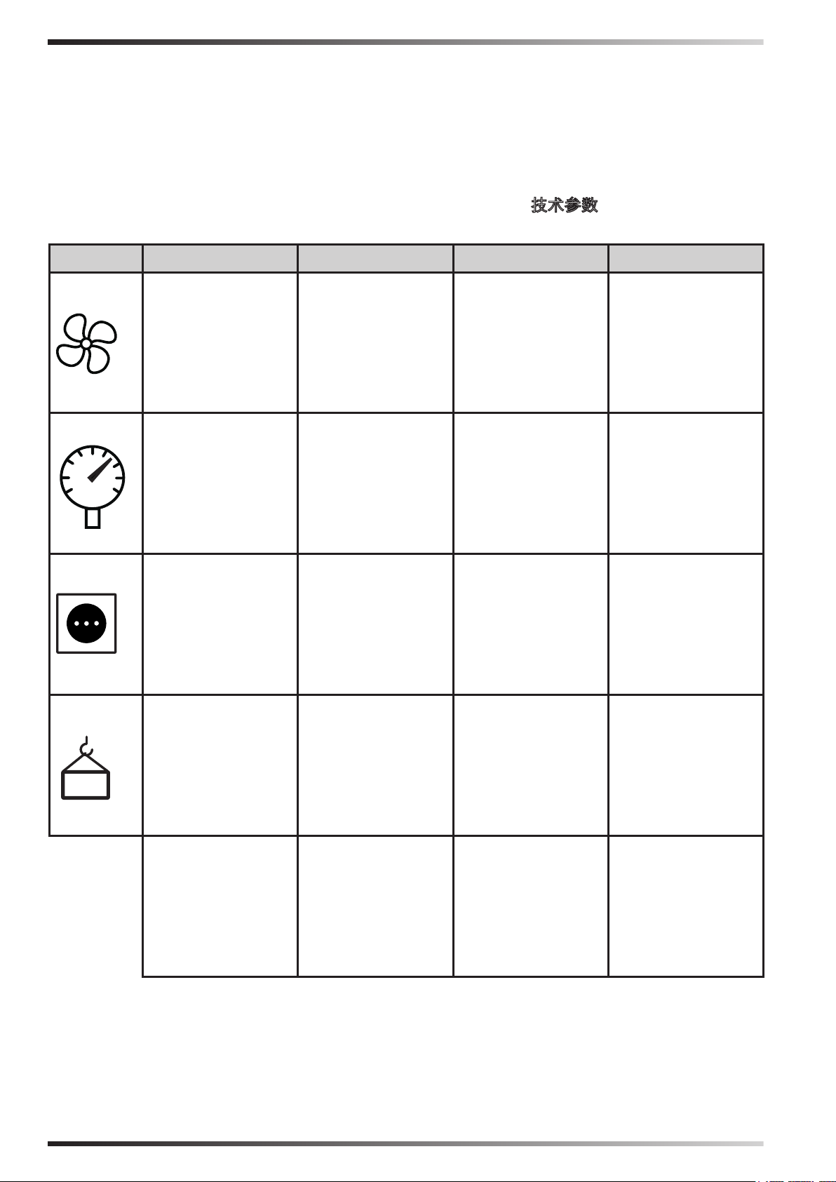
技术参数 - ТЕХНИКАЛЫҚ
MODEL
BCF 230RB BCF 230AB BCF 230AL BCF 230AU
18.000 m³/h-м³/ч 18.000 m³/h-м³/ч 18.000 m³/h-м³/ч 18.000 m³/h-м³/ч
258 Pa-Па 200 Pa-Па 200 Pa-Па 200 Pa-Па
220-240 V-В
50 Hz-Гц
8,4 A
1.500 W-Вт
220-240 V-В
50 Hz-Гц
7,2 A
1.100 W-Вт
220-240 V-В
50 Hz-Гц
7,2 A
1.100 W-Вт
220-240 V-В
50 Hz-Гц
7,2 A
1.100 W-Вт
94 kg-кг 76 kg-кг 76 kg-кг 76 kg-кг
IP55 IP55 IP55 IP55
Figures and texts of this book are protected by COPYRIGHT.
Page 3
PICTURES - FIGURE - ABBILDUNGEN - FIGURAS - FIGURES - FIGUREN
- FIGURAS - FIGURER - KUVAT - FIGURER - FIGURER - ILUSTRACJE
- ИЛЛЮСТРАЦИИ - OBRÁZKY - ÁBRÁK - SLIKE - ŞEKİLLER - SLIKE -
ILIUSTRACIJOS - ATTĒLI - JOONISED - IMAGINI - OBRÁZKY - СХЕМИ - ДАНІ
- ΕΙΚΟΝΕΣ - 图示 - СУРЕТТЕМЕЛЕР
1
2
2
Figures and texts of this book are protected by COPYRIGHT.
Page 4

PICTURES - FIGURE - ABBILDUNGEN - FIGURAS - FIGURES - FIGUREN
- FIGURAS - FIGURER - KUVAT - FIGURER - FIGURER - ILUSTRACJE
- ИЛЛЮСТРАЦИИ - OBRÁZKY - ÁBRÁK - SLIKE - ŞEKİLLER - SLIKE -
ILIUSTRACIJOS - ATTĒLI - JOONISED - IMAGINI - OBRÁZKY - СХЕМИ - ДАНІ
- ΕΙΚΟΝΕΣ - 图示 - СУРЕТТЕМЕЛЕР
65 cm
3
25 cm
15 cm
65 cm
90 cm
3
Figures and texts of this book are protected by COPYRIGHT.
90°
Page 5
PICTURES - FIGURE - ABBILDUNGEN - FIGURAS - FIGURES - FIGUREN
- FIGURAS - FIGURER - KUVAT - FIGURER - FIGURER - ILUSTRACJE
- ИЛЛЮСТРАЦИИ - OBRÁZKY - ÁBRÁK - SLIKE - ŞEKİLLER - SLIKE -
ILIUSTRACIJOS - ATTĒLI - JOONISED - IMAGINI - OBRÁZKY - СХЕМИ - ДАНІ
- ΕΙΚΟΝΕΣ - 图示 - СУРЕТТЕМЕЛЕР
65 cm
3
90 cm
65 cm
25 cm
90°
15 cm
3
Figures and texts of this book are protected by COPYRIGHT.
25 cm
Page 6
PICTURES - FIGURE - ABBILDUNGEN - FIGURAS - FIGURES - FIGUREN
- FIGURAS - FIGURER - KUVAT - FIGURER - FIGURER - ILUSTRACJE
- ИЛЛЮСТРАЦИИ - OBRÁZKY - ÁBRÁK - SLIKE - ŞEKİLLER - SLIKE -
ILIUSTRACIJOS - ATTĒLI - JOONISED - IMAGINI - OBRÁZKY - СХЕМИ - ДАНІ
- ΕΙΚΟΝΕΣ - 图示 - СУРЕТТЕМЕЛЕР
4
5
4
5
6
Figures and texts of this book are protected by COPYRIGHT.
6
Page 7
PICTURES - FIGURE - ABBILDUNGEN - FIGURAS - FIGURES - FIGUREN
- FIGURAS - FIGURER - KUVAT - FIGURER - FIGURER - ILUSTRACJE
- ИЛЛЮСТРАЦИИ - OBRÁZKY - ÁBRÁK - SLIKE - ŞEKİLLER - SLIKE -
ILIUSTRACIJOS - ATTĒLI - JOONISED - IMAGINI - OBRÁZKY - СХЕМИ - ДАНІ
- ΕΙΚΟΝΕΣ - 图示 - СУРЕТТЕМЕЛЕР
7
8
7
8
9
Figures and texts of this book are protected by COPYRIGHT.
10
Page 8
en
PARAGRAPH SUMMARY
1... SAFETY INFORMATION
2... UNPACKING
3... ASSEMBLY AND INSTALLATION
(ONLY FOR QUALIFIED PERSONNEL)
4... ANOMALIES
5... CLEANING AND MAINTENANCE
6... FUNCTIONING ANOMALIES
IMPORTANT: READ AND UNDERSTAND THIS OPERATIONAL MANUAL PRIOR
TO ASSEMBLING, STARTING UP OR CONDUCTING MAINTENANCE ON THIS
COOLER. USING THE COOLER INCORRECTLY CAN CAUSE SERIOUS OR FATAL
INJURIES. KEEP THIS MANUAL FOR FURTHER REFERENCE.
►►1. INFORMATION ON
SAFETY
IMPORTANT: This appliance is not
suitable for use by persons (including
children) with reduced physical,
sensory and mental capacities or
with lack of experience or knowledge
unless supervised by a person
responsible for their safety. Children
must be supervised to make sure they
do not play with the appliance.
►1.1. During installation, the electrical
connection, water connection, use
and maintenance of the cooler,
comply with all local regulations
and standards in force.
►1.2. The cooler must only be
installed, adjusted and serviced by
qualied personnel.
►1.3. Use this appliance to cool,
dehumidify, ventilate or remove
dust.
►1.4. In order to prevent the risk of
re or serious injuries, install the
cooler at a safe distance from heat
sources (replaces, re, etc.), from
sparks (welding machines, electrical
panels, etc.) or from combustion
fumes (hoods, chimney ues, etc.).
►1.5. Improper wiring or improper
installation can cause hazards or
serious damage.
►1.6. Before carrying out any
operation, make sure that the
cooler, the power supply cable, the
control panel, etc., are perfectly dry,
in order to prevent any hazard or
serious damage (never work with
wet hands).
►1.7. Only install outdoors.
►1.8. The cooler must be installed
on a stable and level structure, so
as to prevent any risk (the structure
and the plugs must be adequate to
support the weight of the appliance).
►1.9. The minimum safety distance
recommended between the cooler
and walls or other items is 0.5 m.
►1.10. A 0.8 m
2
outlet for every 3,600
m3/h of air supplied to the cooler
must be provided (always ensure
an exchange of air within the cooled
environment). In the event of forced
air ventilation, the amount extracted
should be less than 85% of the air
intake. Forced ventilation can be
combined with natural ventilation.
►1.11. Power the cooler solely with
the voltage and frequency specied
Figures and texts of this book are protected by COPYRIGHT.
Page 9

en
on the nameplate, using cables of
suitable section (the supply voltage
must not vary more than ± 5% from
the value stated on the nameplate).
►1.12. Make sure that the cooler is
earthed properly.
►1.13. Make sure that during the
electrical connection, the phaseneutral connection is complied
with. We recommend using a 2P
10A differential switch.
►1.14. The cooler can withstand a
maximum water inlet pressure of
3 Bar. If the pressure of the water
supply is higher, a pressure reducer
must be installed.
►1.15. Only ll the cooler tank only
with clean water.
►1.16. We recommend using
horizontal coverage to protect from
weathering, in order to preserve the
cooler over time.
►1.17. It is forbidden to alter, tamper
with or adjust the cooler and the
electricity or water supply after
installation, if it is not carried out by
qualied personnel.
►1.18. Do not obstruct, even partially,
the air vents of the cooler, in order
to prevent a hazard.
►1.19. In order to prevent serious
damage, do not let dust, dirt or other
materials come into contact with the
cooler.
►1.20. We recommend using the
cooler with ambient temperatures
between 18°C and 45°C and with
water temperature below 45°C.
►1.21. In order to prevent serious
breakdowns, when the temperatures
drop to about <2°C, completely
empty the tank and the pipes that
supply water to the cooler.
►1.22. Disconnect the power supply
when you handle or service the
cooler (use personal protective
equipment in order to prevent any
hazards).
►1.23. If the power supply cable is
damaged, it must be replaced by a
technical support centre to prevent
any risk.
►1.24. Protect the power cable from
potential damage caused by the
movement of vehicles, pedestrians,
weathering and heat sources.
►1.25. In the event of the cooler
malfunctions, disconnect the power
supply and contact the technical
support centre.
►1.26. Unplug the cooler from the
power supply, when it is not used
for a medium to long term period.
►1.27. Empty the cooler tank
frequently in order to prevent water
stagnation.
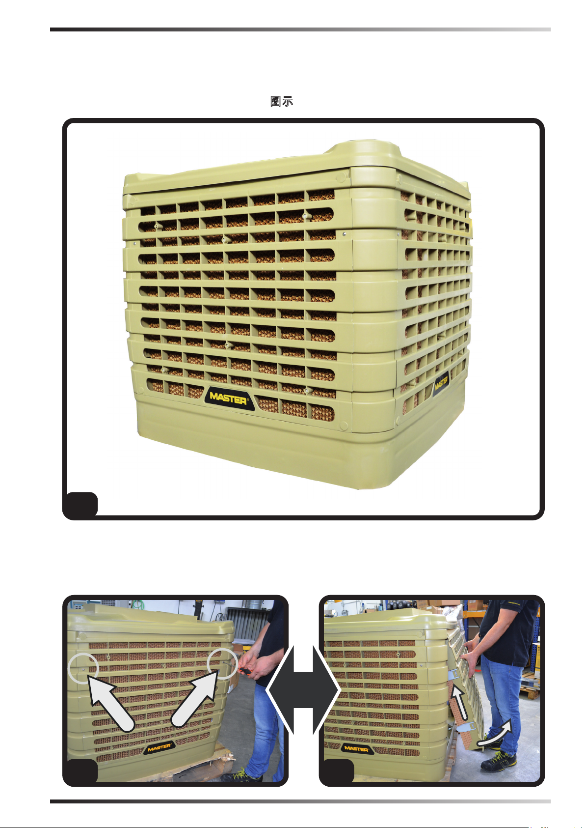
►►2. UNPACKING
(Pic. 1)
IMPORTANT: IT IS STRICTLY
FORBIDDEN TO STACK TWO OR
MORE APPLIANCES.
►2.1. Remove all packaging materials
used to wrap and deliver the appliance
and dispose of them in compliance
with the Standards in force.
►2.2. Extract all articles from the
packaging.
►2.3. Check for any damage undergone
during transport. Immediately inform
the dealer where the appliance was
purchased if this appears damaged.
Figures and texts of this book are protected by COPYRIGHT.
Page 10
en
►►3. ASSEMBLY AND
INSTALLATION (ONLY FOR
QUALIFIED PERSONNEL)
NOTE: TO ACCESS THE INTERNAL
PARTS OF THE COOLER, REMOVE
THE SCREWS AND EVAPORATION
PANELS, REMOVE PANELS LOCATED
ON SIDES OF THE DEVICE (Pic. 2).
►3.1. HANDLING
Handle the cooler with the utmost care,
moving it horizontally.
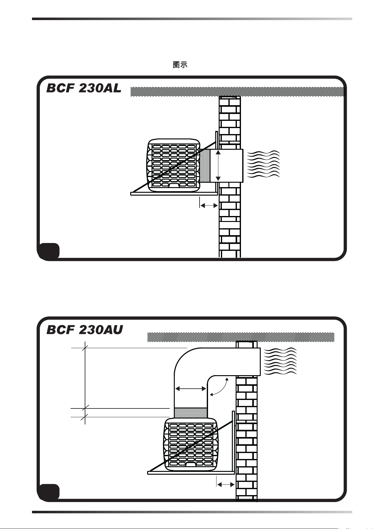
►3.2. PRE-INSTALLATION AND
INSTALLATION METHOD
(Pic. 3):
During installation, the electrical
connection, water connection, use and
maintenance of the cooler, comply with
all local regulations and standards in
force.
►3.2.1. The cooler must be installed
on a stable and level structure, so as to
prevent any risk (the structure and the
plugs must be adequate to support the
weight of the appliance).
►3.2.2. Install the cooler in well ventilated
areas.
►3.2.3. The cooler can only be installed
outside (on the roof or on the wall).
►3.2.4. Install the cooler away from
replaces, heat sources and possible
sparks, in order to prevent serious
damage.
►3.3. DUCTING METHOD
By connecting a conduit to the cooler,
the outgoing air can be carried to where
cooling is required.
It is crucial for the entire ducting conduit
to be designed and structured correctly.
►3.3.1. Use conduits of suitable section
(the average air speed inside the conduit
is 3-6 m/s).
►3.3.2. The ducting should be as short
as possible.
►3.3.3. The pipes must be installed at a
maximum of 4 m above the ground.
►3.3.4. Do not install the duct with elbow
bends.
►3.3.5. The maximum length of the
conduit is 20 m.
►3.3.6. Up to four reductions can be
installed within the conduit.
►3.3.7. The pipe joints must be exible.
►3.3.8. Do not branch the air ow into
several conduits.
NOTE: WE RECOMMEND USING
CONDUITS MADE OF GALVANISED
SHEET METAL, PLASTIC OR
FIBREGLASS.
►3.4. CONNECTION TO THE
ELECTRICITY MAINS
IMPORTANT: THE POWER SUPPLY
AND CONNECTION LINE MUST
BE INSTALLED BY A QUALIFIED
TECHNICIAN USING SUITABLE
DEVICES AND INSTRUMENTS, IN
ACCORDANCE WITH NATIONAL
REGULATIONS AND THE STANDARDS
IN FORCE.
►3.4.1. By removing the screws on the
side of the cooler you have access to the
interior of the appliance (Pic. 2).
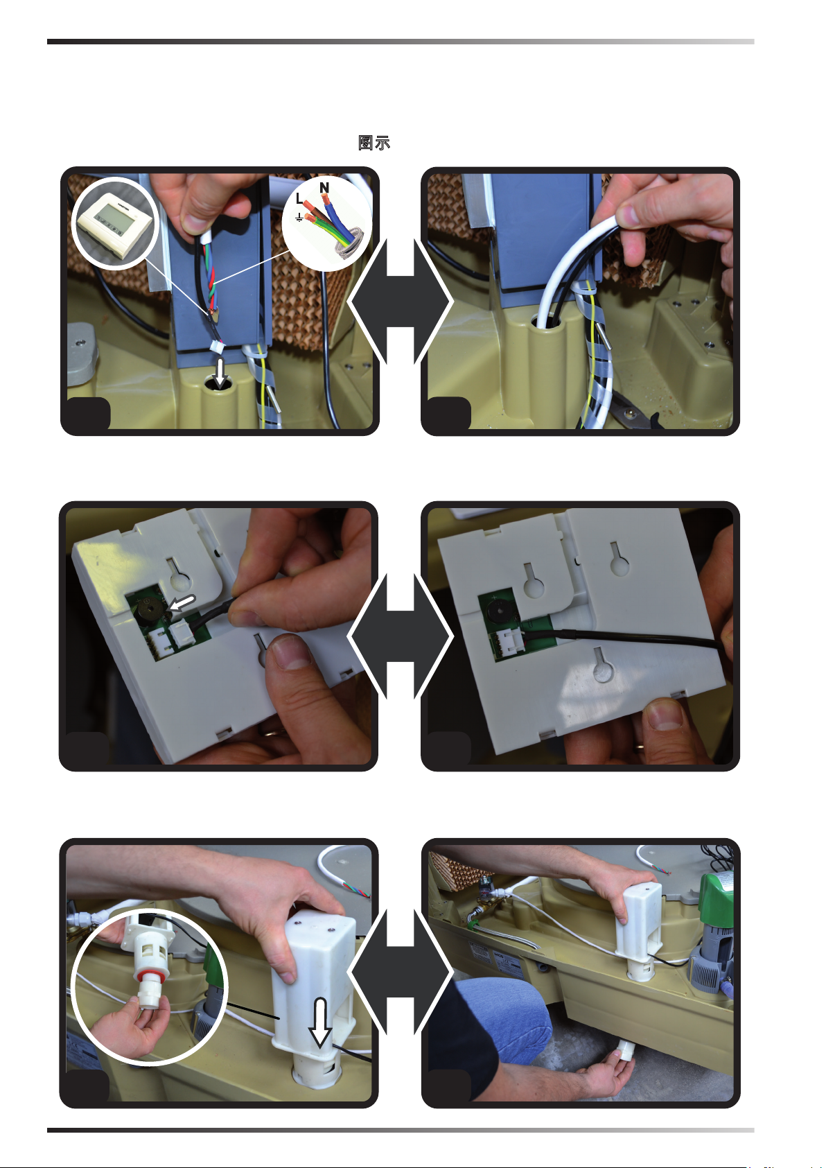
►3.4.2. Feed the electrical cables
(power cable and the control panel cable)
through the hole near the electrical panel
(Pic. 4).
►3.4.3. Only connect and power the
cooler with the voltage and frequency
specied on the nameplate and with
cables of suitable section (observing the
phase-neutral polarity).
Figures and texts of this book are protected by COPYRIGHT.
Page 11
en
►3.4.4. For proper operation it is crucial
to connect the earth to the cooler properly.
►3.4.5. Connect the control panel, using
the specic connector (Pic. 5).
NOTE: WE RECOMMEND USING A 2P
10A DIFFERENTIAL SWITCH.
►3.5. INSTALLING THE DRAIN
VALVE
(Pic. 6)
At the base of the cooler, to drain water
from the tank, the cooler is equipped with
a drain valve.
At the time of purchase, the drain valve
comes in the kit supplied.
To install the valve you must:
►3.5.1. Remove the nut installed at the
base of the valve.
►3.5.2. Insert the valve into its seat
(located at the base of the cooler).
►3.5.3. Screw the nut back onto the
valve.
►3.7. BASIC CONFIGURATION
(Pic. 8)
IMPORTANT: THE BASIC
CONFIGURATION OF THE COOLER
MUST BE CARRIED OUT FROM
THE CONTROL PANEL. THE
CONFIGURATION MUST BE CARRIED
OUT WITH THE COOLER SWITCHED
OFF, BUT POWERED FROM THE
ELECTRICAL MAINS.
►DRAIN: (Press and hold the DRAIN
button for a few seconds): You can then
access the sub-menu that allows you
to set every how many hours the cooler
must automatically drain the water from
the tank (with the value at “0” the tank
is never drained automatically).
►VENTOLA (FAN): (Press and hold
the VENTOLA (FAN) button for a few
seconds): You can then access the submenu that allows you to set the direction
of fan rotation [(0= clockwise, to let air
into the room) (1= anticlockwise, to let
air out of the room)].
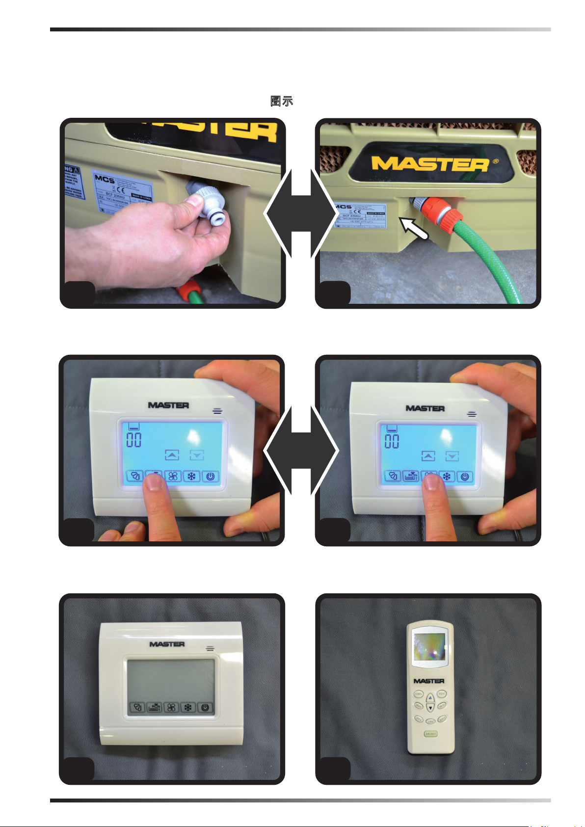
►3.6. CONNECTING TO THE WATER
MAINS
(Pic. 7)
IMPORTANT: ONLY FEED THE
COOLER WITH CLEAN WATER.
IMPORTANT: THE COOLER CAN
WITHSTAND A MAXIMUM WATER
INLET PRESSURE OF 3 BAR. THE
PIPES AND FITTINGS USED FOR
THE WATER SUPPLY MUST BE
OF ADEQUATE SECTION AND
STRUCTURE (IF THE PRESSURE
OF THE WATER MAINS IS HIGH, WE
RECOMMEND USING A PRESSURE
REDUCER AND A METAL MESH PIPE).
►3.6.1. Connect the cooler to the water
mains using the threaded tting.
►3.6.2. Make sure that there are no water
leaks in the circuit before commissioning.
►►4. ANOMALIES
WARNING: Carefully read the
“SAFETY INFORMATION” before
switching on the cooler.
WARNING: Only use clean water to
prevent failures or other anomalies.
WARNING: Verify if your electronic
system is earthed correctly.
Connection to the electrical mains
must be carried out in compliance
with the national standards in force.
Only power the appliance the with
voltage and frequency as specied on
the nameplate.
Figures and texts of this book are protected by COPYRIGHT.
Page 12
en
IMPORTANT: The cooler is equipped
with a water drain, located at the base
of the appliance. Depending on the
setting, the cooler will drain the water
from the tank completely, in order to
prevent water stagnation. In any case,
it is recommended to drain the water
from the tank frequently.
During the winter season or in the
event of a long period of inactivity,
drain the circuit and water tank
completely.
NOTE: It is recommended to drain
the water from the tank before each
shutdown.
►4.1. CONTROL PANEL AND
FUNCTIONS
(Pic. 9)
►ON/OFF: Is used to turn the cooler on
or off.
►ARROW ↑↓: Increases or decreases
the ventilation speed.
►COOL: Enables or disables the cooling
mode.
►FAN: Enables the ventilation mode
only.
►SWING (Set-up): The function enables
or disables the automatic swing of the
ns to direct the air ow.
►DRAIN: Drains the water from the tank.
NOTE: When the control panel display
shows the icon “TANK” (ashing),
accompanied by a beep, it means that
the tank is empty and must be relled
again to reactivate the COOL function.
►4.2. REMOTE CONTROL AND
FUNCTIONS
(Pic. 10)
►ON/OFF: Is used to turn the cooler on
or off.
►ARROW ↑↓: Increases or decreases
the ventilation speed.
►COOL: Enables or disables the cooling
mode.
►VENT (FAN): Enables the ventilation
mode only.
►SWING (Set-up): The function enables
or disables the automatic swing of the
ns to direct the air ow.
►DRAIN: Drains the water from the tank.
►LIGHT: Activates the light on the
display.
►HOUR and MINUTE: Adjusts the time
on the remote control.
►4.3. SWITCH-OFF
►4.3.1. Drain the water from the tank
using the DRAIN function.
►4.3.2. Press the ON/OFF button to
switch the cooler off (the continuous
ventilation for a few minutes allows the
evaporation panels to dry).
►4.3.3. When the cooler is not used,
disconnect the electrical power supply
and the water supply.
►►5. CLEANING AND
MAINTENANCE
WARNING: BEFORE CARRYING OUT
ANY MAINTENANCE OR REPAIRS,
DISCONNECT THE APPLIANCE FROM
THE MAINS POWER AND WATER
SUPPLY.
Depending on the environment where
the appliance is used, dust, dirt, etc. can
affect the performance of the cooler. We
therefore recommend cleaning (never
clean with a high pressure water jet) the
outside of the cooler with a soft cloth,
removing any obstructions from the air
vents.
Figures and texts of this book are protected by COPYRIGHT.
Page 13
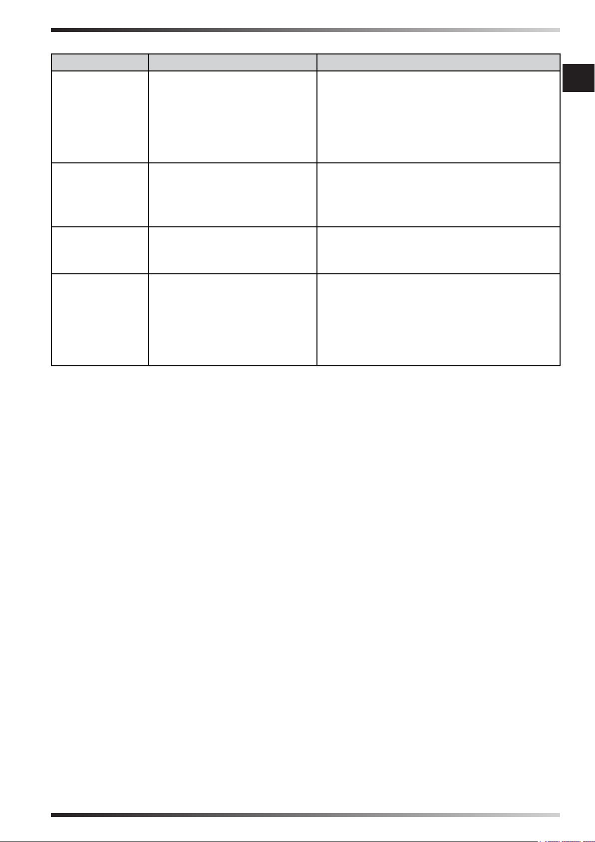
►►6. TROUBLESHOOTING
FAULT CAUSE SOLUTION
en
The display
does not work
There is no
air ow or it is
very low
The device
does not respond to the
commands
The device
leaks water
1. No power supply
1a. Make sure that the device is con-
nected to the power supply
1b. Make sure that the display is con-
nected to the cable
1c. Contact a support centre
2. Defective equipment
1. Obstructed air vents
2. Contact a support centre
1a. Remove any objects from the air
vent
1b. Contact a support centre
2. Defective equipment
2. Contact a support centre
1. Defective equipment 1. Contact a support centre
1. The water supply pipe is
1. Tighten the tting
loose
2. The water drain is dirty
3. The tank leaks
4. The panel is dripping
2. Contact a support centre
3. Contact a support centre
4. Contact a support centre
Figures and texts of this book are protected by COPYRIGHT.
Page 14
it
SOMMARIO PARAGRAFI
1... INFORMAZIONI SULLA SICUREZZA
2... DISIMBALLAGGIO
3... ASSEMBLAGGIO E INSTALLAZIONE
(SOLO PER PERSONALE QUALIFICATO)
4... FUNZIONAMENTO
5... PULIZIA E MANUTENZIONE
6... ANOMALIE DI FUNZIONAMENTO
IMPORTANTE: LEGGERE E COMPRENDERE QUESTO MANUALE OPERATIVO
PRIMA DI EFFETTUARE L’ASSEMBLAGGIO, LA MESSA IN FUNZIONE O
LA MANUTENZIONE DI QUESTO RAFFRESCATORE. L’USO ERRATO DEL
RAFFRESCATORE PUÒ CAUSARE LESIONI GRAVI O FATALI. CONSERVARE
QUESTO MANUALE A TITOLO DI FUTURO RIFERIMENTO.
►►1. INFORMAZIONI SULLA
SICUREZZA
IMPORTANTE: Questo apparec-
chio non è adatto all’uso da parte di
persone (incluse bambini) con capacità siche, sensoriali e mentali ridotte, o inesperte, a meno che non
vengano supervisionate da una persona reponsabile per la loro sicurezza. I bambini devono essere controllati, per assicurarsi che non giochino
con l’apparecchio.
►1.1. Durante l’installazione, la
connessione elettrica, la connessione
idrica, l’uso e la manutenzione del
raffrescatore, attenersi a tutte le
ordinanze locali ed alla normativa
vigente.
►1.2. L’installazione, la regolazione,
la manutenzione del raffrescatore va
eseguita solo da personale qualicato.
►1.3. Usare questo apparecchio per
raffrescare, umidicare, ventilare o
eliminare la polvere.
►1.4. Al ne di evitare il rischio di
incendio o di lesioni gravi, installare
il raffrescatore a distanza di sicurezza
da fonti di calore (camini, fuoco, ecc.),
da scintille (saldatrici, quadri elettrici,
ecc.) o da fumi di combustione (cappe,
canne fumarie, ecc.).
►1.5. Il collegamento elettrico
improprio o l’installazione impropria,
può provocare rischio o gravi guasti.
►1.6. Prima di effettuare qualsiasi
operazione, assicurarsi che il
raffrescatore, il cavo di alimentazione,
il pannello comandi, ecc., siano
perfettamente asciutti, al ne di
prevenire ogni rischio o gravi guasti
(non operare mai con le mani bagnate).
►1.7. Installare solo all’esterno.
►1.8. Il raffrescatore deve essere
installato su una struttura stabile
e livellata, in modo da evitare ogni
rischio (la struttura e i tasselli devono
essere adeguati a supportare il peso
dell’apparecchio).
►1.9. La distanza minima di sicurezza,
consigliata, intercorrente tra il
raffrescatore e pareti o altri oggetti è
0,5 m.
►1.10. Si deve predisporre un uscita
2
di 0,8 m
per ogni 3.600 m3/h di aria
fornita al raffrescatore (garantire
sempre un ricambio d’aria all’interno
dell’ambiente raffrescato). In caso
di ventilazione forzata dell’aria,
la quantità estratta dovrà essere
inferiore all’85% dell’aria introdotta.
La ventilazione forzata può essere
abbinata alla ventilazione naturale.
Figures and texts of this book are protected by COPYRIGHT.
Page 15
►1.11. Alimentare il raffrescatore
solamente con tensione e frequenza
specicata sulla targa dati, utilizzando
cavi di adeguata sezione (la tensione
di alimentazione non deve variare più
del ± 5% rispetto al valore dichiarato
sulla targa dati).
►1.12. Assicurarsi che il raffrescatore
sia opportunamente collegato a
massa.
►1.13. Assicurarsi che nel momento
del collegamento elettrico, siano
rispettate la connessione fase-neutro.
Si consiglia l’utilizzo di un interruttore
differenziale di tipo 2P 10A.
►1.14. Il raffrescatore può supportare
una pressione massima d’ingresso
acqua di 3 Bar. Se la pressione della
fornitura idrica dovesse essere
maggiore, è necessario installare un
riduttore di pressione.
►1.15. Rifornire il serbatoio del
raffrescatore solamente con acqua
pulita.
►1.16. Si consiglia l’uso di copertura
orizzontale a protezione degli agenti
atmosferici, al ne di preservare il
raffrescatore nel tempo.
►1.17. É vietata qualsiasi modica,
manomissione, regolazione del
raffrescatore e della rete elettrica o
idrica dopo l’installazione, se non è
effettuata da personale qualicato.
►1.18. Non ostruire, neanche
parzialmente, le prese d’aria del
raffrescatore, in modo da prevenire
ogni rischio.
►1.19. Al ne di evitare gravi guasti,
evitare che polvere, sporco o altri
materiali, vadano a contatto con il
raffrescatore.
►1.20. Si consiglia di utilizzare il
raffrescatore con temperature
ambiente comprese tra 18°C e 45°C e
con temperatura dell’acqua inferiore a
45°C.
►1.21. Al ne di evitare gravi guasti,
quando le temperature si abbassano a
circa < 2°C, svuotare completamente il
serbatoio e i condotti che riforniscono
it
l’acqua al raffrescatore.
►1.22. Scollegare l’alimentazione
elettrica quando si maneggia o si
fa manutenzione al raffrescatore
(utilizzare protezioni personali al ne
di prevenire ogni rischio).
►1.23. Se il cavo di alimentazione risulta
danneggiato, deve essere sostituito
dal centro assistenza tecnica, in modo
da prevenire ogni rischio.
►1.24. Proteggere il cavo di
alimentazione da potenziali danni
derivati dal movimento di veicoli,
pedoni, agenti atmosferici e fonti di
calore.
►1.25. In caso di malfunzionamento
del raffrescatore, scollegare
l’alimentazione elettrica e contattare
il centro di centro assistenza tecnica.
►1.26. Scollegare il raffrescatore
dall’alimentazione, quando non viene
utilizzato per un medio-lungo periodo.
►1.27. Svuotare frequentemente il
serbatoio del raffrescatore al ne di
evitare ristagni d’acqua.
►►2. DISIMBALLAGGIO
(Fig. 1)
IMPORTANTE: È ASSOLUTAMENTE
VIETATO IMPILARE A DUE O PIÙ UNITÀ
GLI APPARECCHI.
►2.1. Rimuovere tutti i materiali di
imballaggio usati per confezionare e
spedire l’apparecchio e smaltirli secondo
le norme vigenti.
►2.2. Estrarre tutti gli articoli dall’imballo.
►2.3. Controllare eventuali danni subiti
durante il trasporto. Se l’apparecchio
appare danneggiato, informare
immediatamente il concessionario
presso il quale è stato acquistato.
Figures and texts of this book are protected by COPYRIGHT.
Page 16
►►3. ASSEMBLAGGIO E
it
INSTALLAZIONE (SOLO PER
PERSONALE QUALIFICATO)
NOTA: PER ACCEDERE ALLE PARTI
INTERNE DEL RAFFRESCATORE,
RIMUOVERE LE VITI E I PANNELLI
EVAPORATIVI, POSIZIONATI SUI
FIANCHI DELL’APPARECCHIO (Fig. 2).
►3.1. MOVIEMENTAZIONE
Movimentare il raffrescatore con la
massima cura, spostandolo in posizione
orizzontale.
►3.3.2. La canalizzazione deve essere più
corta possibile.
►3.3.3. Le tubazioni devono essere
installate al massimo a 4 m di altezza dal
suolo.
►3.3.4. Evitare curve a gomito del
condotto.
►3.3.5. La lunghezza massima del
condotto deve essere 20 m.
►3.3.6. Si devo installare al massimo
quattro riduzioni all’interno del condotto.
►3.3.7. Le giunzioni del tubo devono
essere essibili.
►3.3.8. Evitare di diramare il usso dell’aria
in più condotti e sotto condotti.
►3.2. PREINSTALLAZIONE E METODO
DI INSTALLAZIONE
(Fig. 3)
Durante l’installazione, la connessione
elettrica, la connessione idrica, l’uso e la
manutenzione del raffrescatore, attenersi a
tutte le ordinanze locali ed alla normativa
vigente.
►3.2.1. Il raffrescatore deve essere
installato su una struttura stabile e livellata,
in modo da evitare ogni rischio (la struttura
e i tasselli devono essere adeguati a
supportare il peso dell’apparecchio).
►3.2.2. Installare il raffrescatore in aree
ben ventilate.
►3.2.3. Il raffrescatore può essere installato
solo all’esterno (sul tetto o a parete).
►3.2.4. Installare il raffrescatore lontano
da camini, fonti di calore e possibili scintille,
al ne di evitare gravi danni.
►3.3. METODO DI CANALIZZAZIONE
Collegando un condotto al raffrescatore,
si può trasportare l’aria in uscita dove è
necessario raffrescare.
É importante che l’intero condotto di
canalizzazione sia progettato e strutturato
in modo corretto.
►3.3.1. Utilizzare condotti di adeguata
sezione (la velocità media dell’aria
all’interno del condotto è 3-6 m/s).
NOTA: SI CONSIGLIA DI UTILIZZARE
CONDOTTI IN LAMIERA ZINCATA,
PLASTICA O VETRORESINA.
►3.4. COLLEGAMENTO ALLA RETE
ELETTRICA
IMPORTANTE: LA REALIZZAZIONE
DELLA LINEA DI ALIMENTAZIONE
ELETTRICA E DELL’ALLACCIAMENTO
DEVE ESSERE EFFETTUATA DA UN
TECNICO ABILITATO, UTILIZZANDO
DISPOSITIVI E STRUMENTI IDONEI,
SECONDO LA REGOLAMENTAZIONE
NAZIONALE E IN LINEA CON LE NORME
VIGENTI.
►3.4.1. Rimovendo le viti sul anco del
raffrescatore si ha accesso all’interno
dell’apparecchio (Fig. 2).
►3.4.2. Far passare i cavi elettrici (cavo
di alimentazione e il cavo del pannello
comandi) attraverso il foro posizionato
vicino al pannello elettrico (Fig. 4).
►3.4.3. Collegare e alimentare il
raffrescatore solamente con tensione e
frequenza specicata sulla targa dati e con
cavi di adeguata sezione (rispettando le
polarità fase-neutro).
►3.4.4. Per il corretto funzionamento è
fondamentale collegare correttamente la
messa a terra al raffrescatore.
►3.4.5. Collegare il pannello comandi,
tramite lo specico connettore (Fig. 5).
Figures and texts of this book are protected by COPYRIGHT.
Page 17
NOTA: SI CONSIGLIA L’UTILIZZO DI UN
INTERRUTTORE DIFFERENZIALE DI
TIPO 2P 10A.
►3.5. INSTALLAZIONE VALVOLA DI
SCARICO
(Fig. 6)
Alla base del raffrescatore, per drenare
l’acqua dal serbatoio, il raffrescatore è
dotato di una valvola di scarico.
La valvola di scarico al momento
dell’acquisto è posizionata all’interno del
corredo di vendita.
Per installare la valvola di scarico si deve:
►3.5.1. Rimuovere il dado installato alla
base della valvola.
►3.5.2. Inserire la valvola nell’apposita sede
(posizionato alla base del raffrescatore).
►3.5.3. Riavvitare il dado sulla valvola.
►3.6. COLLEGAMENTO ALLA RETE
IDRICA
(Fig. 7)
IMPORTANTE: ALIMENTARE IL
RAFFRESCATORE SOLO CON ACQUA
PULITA.
IMPORTANTE: IL RAFFRESCATORE
PUÒ SUPPORTARE UNA PRESSIONE
MASSIMA D’INGRESSO ACQUA DI 3
BAR. LE TUBAZIONI E I RACCORDI
UTILIZZATI PER L’ALIMENTAZIONE
IDRICA, DEVONO ESSERE DI
ADEGUATE SEZIONE E STRUTTURA
(SE LA PRESSIONE DELLA RETE IDRICA
È ELEVATA, SI CONSIGLIA L’USO DEL
RIDUTTORE DI PRESSIONE E DI UNA
TUBAZIONE CON MAGLIA METALLICA).
►3.6.1. Collegare il raffrescatore alla rete
idrica tramite il raccordo lettato.
►3.6.2. Vericare che non si presentino
perdite d’acqua del circuito, prima della
messa in funzione.
►3.7. CONFIGURAZIONE DI BASE
(Fig. 8)
IMPORTANTE: LA CONFIGURAZIONE
DI BASE DEL RAFFRESCATORE VA
EFFETTUATA DAL PANNELLO DI
CONTROLLO. LA CONFIGURAZIONE
VA ESEGUITA A RAFFRESCATORE
SPENTO, MA ALIMENTATO DALLA
RETE ELETTRICA.
►DRAIN: (Tenere premuto per alcuni
secondi il pulsante DRAIN): Si entra nel
sottomenù che permette di impostare ogni
quante ore il raffrescatore in automatico
deve scaricare l’acqua dal serbatoio (con
il valore a “0” il serbatoio non viene mai
scaricato in automatico).
►VENTOLA: (Tenere premuto per alcuni
secondi il pulsante VENTOLA): Si
entra nel sottomenù che permette di
impostare il senso di rotazione della
ventola [(0= orario, per immettere aria
in ambiente) (1= antiorario, per sottrare
aria dall’ambiente)].
►►4. FUNZIONAMENTO
it
AVVERTENZA: Leggere attentamente
le ”INFORMAZIONI SULLA
SICUREZZA”, prima di accendere il
raffrescatore.
AVVERTENZA: Usare solamente
acqua pulita, per evitare guasti o altre
anomalie.
AVVERTENZA: Vericare la corretta
messa a terra del vostro impianto
elettrico. Il collegamento alla rete
elettrica va eseguito in accordo con
le norme nazionali vigenti. Alimentare
l’apparecchio solamente con tensione
e frequenza specicata sulla targa
dati.
Figures and texts of this book are protected by COPYRIGHT.
Page 18
it
IMPORTANTE: Il raffrescatore è dotato
di scarico dell’acqua, posizionato alla
base dell’apparecchio. A seconda del
settaggio, il raffrescatore scaricherà
completamente l’acqua dal serbatoio,
al ne di evitare ristagno di acqua. Ad
ogni modo, si consiglia di scaricare
l’acqua dal serbatoio frequentemente.
Nella stagione invernale o in caso
si un lungo periodo di inutilizzo,
vuotare completamente il circutio e il
serbatoio delL’acqua.
NOTA: Si consiglia di scaricare
l’acqua dal serbatoio prima di ogni
spegnimento.
►FRECCIA ↑↓: Permette di aumentare o
diminuire la velocità di ventilazione.
►COOL: Permette di attivare o disattivare
la modalità raffrescamento.
►VENT: Permette di attivare la modalità
solo ventilazione.
►SWING (Predisposizione): È la
predisposizione che permette di attivare
o disattivare l’oscillazione automatica
delle alette per direzionare il usso d’aria.
►DRAIN: Permette di scaricare l’acqua
dal serbatoio.
►LIGHT: Permette di accendere la luce
sul display.
►HOUR e MINUTE: Permette di regolare
l’orario del telecomando.
►4.1. PANNELLO DI CONTROLLO E
FUNZIONI
(Fig. 9)
►ON/OFF: Permette di accendere o
spegnere il raffrescatore.
►FRECCIA ↑↓: Permette di aumentare o
diminuire la velocità di ventilazione.
►COOL: Permette di attivare o disattivare
la modalità raffrescamento.
►VENTOLA: Permette di attivare la
modalità solo ventilazione.
►SWING (Predisposizione): È la
predisposizione che permette di attivare
o disattivare l’oscillazione automatica
delle alette per direzionare il usso d’aria.
►DRAIN: Permette di scaricare l’acqua
dal serbatoio.
NOTA: Quando sul display del
pannello di controllo appare l’icona
”SERBATOIO” (lampeggiando),
accompagnata da un bip acustico,
signica che il serbatoio è vuoto e va
riempito nuovamente per riattivare la
funzione COOL.
►4.2. TELECOMANDO REMOTO E
FUNZIONI
(Fig. 10)
►ON/OFF: Permette di accendere o
spegnere il raffrescatore.
►4.3. SPEGNIMENTO
►4.3.1. Scaricare l’acqua dal serbatoio
con l’apposita funzione DRAIN.
►4.3.2. Premere il pulsante ON/OFF per
spegnere il raffrescatore (la ventilazione
continua per alcuni minuti per permettere
ai pannelli evaporativi di asciugarsi).
►4.3.3. Quando il raffrescatore non viene
utilizzato, scollegare l’alimentazione
elettrica e l’alimentazione idrica.
►►5. PULIZIA E MANUTENZIONE
AVVERTENZA: PRIMA DI
EFFETTUARE QUALSIASI
MANUTENZIONE O RIPARAZIONE,
SCOLLEGARE L’ALIMENTAZIONE
ELETTRICA E L’ALIMENTAZIONE
IDRICA.
A seconda dell’ambiente in cui
l’apparecchio viene impiegato, la polvere,
lo sporco, ecc., possono inuire sulle
prestazioni del raffrescatore. Quindi si
consiglia di pulire con un panno morbido
(assolutamente non pulire con un getto
d’acqua ad alta pressione) la parte esterna
del raffrescatore, rimuovendo eventuali
ostruzioni delle prese d’aria.
Figures and texts of this book are protected by COPYRIGHT.
Page 19
►►6. ANOMALIE DI FUNZIONAMENTO
ANOMALIA CAUSA SOLUZIONE
it
Il display non
funziona
Non c’è usso d’aria o è
molto basso
Il dispositivo
non risponde
ai comandi
Il dispositivo
perde acqua
1. Mancanza alimentazione
1a. Controllare che il dispositivo sia col-
legato all’alimentazione
1b. Controllare che il display sia collega-
to al cavo
1c. Contattare il centro di assistenza
2. Apparecchiatura difettosa
1. Ostruzione delle prese
d’aria
2. Contattare il centro di assistenza
1a. Rimuovere eventuali oggetti dalla
presa d’aria
1b. Contattare il centro di assistenza
2. Apparecchiatura difettosa
2. Contattare il centro di assistenza
1. Apparecchiatura difettosa 1. Contattare il centro di assistenza
1. Il tubo di fornitura idirca è
1. Avvitare il racordo
allentato
2. Lo scarico acqua è sporco
3. Il serbatoio perde
4. Il pannello gocciola
2. Contattare il centro di assistenza
3. Contattare il centro di assistenza
4. Contattare il centro di assistenza
Figures and texts of this book are protected by COPYRIGHT.
Page 20
ZUSAMMENFASSUNG DER ABSCHNITTE
de
1... SICHERHEITSHINWEISE
2... AUSPACKEN
3... ZUSAMMENBAU UND MONTAGE
(NUR FÜR AUSGEBILDETES PERSONAL)
4... BETRIEB
5... REINIGUNG UND WARTUNG
6... BETRIEBSSTÖRUNGEN
WICHTIGER HINWEIS: DIESE BEDIENUNGSANLEITUNG MUSS VOR
ZUSAMMENBAU, INBETRIEBSETZUNG ODER WARTUNG DIESER KÜHLUNG
GELESEN UND VERSTANDEN WORDEN SEIN. FALSCHER GEBRAUCH DER
KÜHLUNG KANN ZU SCHWEREN VERLETZUNGEN FÜHREN, AUCH MIT
TÖDLICHEM AUSGANG. BEWAHREN SIE DIESE ANLEITUNG ZUM SPÄTEREN
NACHSCHLAGEN GUT AUF.
►►1. INFORMATIONEN ZUR
SICHERHEIT
WICHTIGER HINWEIS: Dieses Gerät
ist nicht geeignet für den Gebrauch
durch Personen (einschließlich
Kindern) mit eingeschränkten
körperlichen, sensorischen und
geistigen Fähigkeiten bzw. ohne
ausreichende Fachkenntnis, es
sei denn, sie werden durch eine
für ihre Sicherheit verantwortliche
Person beaufsichtigt. Kinder sind zu
beaufsichtigen, damit sie nicht mit
dem Gerät spielen.
►1.1. Bei der Montage, beim Strom- und
Wasseranschluss, bei der Verwendung
und Wartung der Kühlung sind die
örtlichen Vorschriften und die geltenden
Gesetze zu befolgen.
►1.2. Montage, Einstellung und Wartung
des Kühlers sind ausschließlich
ausgebildetem Personal vorbehalten.
►1.3. Dieses Gerät dient zur Kühlung,
Luftbefeuchtung, Ventilation oder
Beseitigung von Staub.
►1.4. Um der Gefahr eines Brandes
oder schwerer Verletzungen
vorzubeugen, ist die Kühlung in
einem Sicherheitsabstand von
Hitzequellen (Kamine, Feuer usw.), von
Funkensprühung (Schweißmaschinen,
elektrischen Schaltschränken oder von
Verbrennungsrauch (Rauchhauben,
Rauchabzüge usw.) aufzustellen.
►1.5. Ein ordnungswidriger
Stromanschluss oder auch eine
ordnungswidrige Aufstellung können
Risiken oder schwere Störungen
bewirken.
►1.6. Vor jeglichem Vorgang
sicherstellen, dass die Kühlung, das
Versorgungskabel und die Bedientafel
vollständig trocken sind, um jegliches
Risiko oder schwere Störungen zu
vermeiden (nie mit nassen Händen am
Gerät hantieren).
►1.7. Nur im Freien aufstellen.
►1.8. Die Kühlung muss zur Vermeidung
jeder Art von Risiko auf einer festen
und nivellierten Struktur aufgestellt
werden (Struktur und Dübel müssen
eine ausreichende Belastbarkeit für das
Gewicht des Geräts aufweisen).
►1.9. Der empfohlene Mindest-
Sicherheitsabstand zwischen Gerät und
Wänden oder anderen Gegenständen
beträgt 0,5 m.
3
►1.10. Für alle 3.600 m
der Kühlung zugeführt wird, muss
ein Ausgang von 0,8 m2 vorhanden
sein (im gekühlten Raum ist stets
für Luftzirkulation zu sorgen). Bei
/h Luft, die
Figures and texts of this book are protected by COPYRIGHT.
Page 21
Zwangsbelüftung muss die extrahierte
Menge unter 85% der zugeführten Luft
sein. Die Zwangsbelüftung kann mit der
natürlichen Lüftung kombiniert werden.
►1.11. Die Kühlung darf ausschließlich
mit der am Typenschild angegebenen
Spannung und Frequenz unter
Verwendung von Kabeln mit
geeignetem Querschnitt versorgt
werden (die Versorgungsspannung
darf nicht mehr als ± 5% von dem am
Schild angegebenen Wert abweichen.
►1.12. Sicherstellen, dass die Kühlung
zweckentsprechend geerdet ist.
►1.13. Sicherstellen, dass beim
elektrischen Anschluss Phasenund Nullleiter richtig angeschlossen
werden. Es ist die Verwendung eines FI-
Schutzschalters Typ 2P 10A angeraten.
►1.14. Die Kühlung hält einem Druck des
einlaufenden Wassers von höchstens 3
bar stand. Sollte das gelieferte Wasser
einen höheren Druck aufweisen, ist ein
Druckminderer zu installieren.
►1.15. Den Tank des Gerätes nur mit
sauberem Wasser befüllen.
►1.16. Zum Schutz gegen
Witterungseinüsse und somit für eine
lange Nutzdauer der Kühlung empehlt
sich eine horizontale Abdeckung.
►1.17. Jede beliebige Änderung,
Manipulation, Einstellung der Kühlung
und des Strom- oder Wassernetzes nach
der Aufstellung darf ausschließlich von
ausgebildetem Personal durchgeführt
werden.
►1.18. Die Luftklappen der Kühlung
dürfen nie, selbst teilweise, verstopft
werden, um jedem Risiko vorzubeugen.
►1.19. Zur Vermeidung von schweren
Schäden ist darauf zu achten, dass
weder Staub noch anderes Material mit
der Kühlung in Berührung kommen.
►1.20. Die Verwendung der Kühlung
empehlt sich bei Raumtemperaturen,
die zwischen 18°C und 45°C liegen und
mit einer Wassertemperatur von unter
45°C.
►1.21. Zur Vermeidung einer schweren
Beschädigung sind, wenn die
Temperaturen auf ca. < 2°C abfallen,
der Tank und die Rohrleitungen, in
denen das Wasser zur Kühlung ießt,
vollständig zu entleeren.
►1.22. Vor dem Hantieren oder
Wartungseingriffen an der Kühlung
ist diese spannungslos zu schalten
(persönliche Schutzausrüstungen zur
Vermeidung sämtlicher Risiken tragen).
►1.23. Wenn das Netzkabel beschädigt
ist, muss es durch den Kundendienst
ausgetauscht werden, um Gefahren
auszuschließen.
►1.24. Das Netzkabel gegen mögliche
Schäden schützen, die durch
die Bewegung von Fahrzeugen,
Fußgänger, atmosphärische Einüsse
und Hitzequellen bewirkt sind.
►1.25. Die Kühlung bei Auftreten von
Betriebsstörungen spannungsfrei
schalten und sich an eine technische
Kundendienststelle wenden.
►1.26. Die Kühlung vor längeren
Stillstandzeiten von der
Stromversorgung abtrennen.
►1.27. Den Tank der Kühlung zur
Vermeidung von Wasserstau oftmalig
entleeren.
►►2. AUSPACKEN
(Abb. 1)
WICHTIGER HINWEIS: ES IST ABSOULT
VERBOTEN, DIE GERÄTE AUF ZWEI ODER
MEHRERE EINHEITEN AUFZUSTAPELN.
►2.1. Entfernen Sie alle für Verpackung
und Versand des Geräts verwendeten
Materialien und entsorgen Sie diese
vorschriftsgemäß.
►2.2. Nehmen Sie alle Artikel aus der
Verpackung.
►2.3. Kontrollieren, ob Transportschäden
vorliegen. Wenn das Gerät beschädigt ist,
sofort den Vertragshändler informieren,
bei dem es erworben wurde.
de
Figures and texts of this book are protected by COPYRIGHT.
Page 22

►►3. ZUSAMMENBAU
UND AUFSTELLUNG (NUR
AUSGEBILDETEM PERSONAL
de
VORBEHALTEN)
HINWEIS: FÜR DEN ZUGRIFF
ZU DEN INNEREN TEILEN DER
KÜHLUNG SIND SCHRAUBEN
UND VERDAMPFUNGSPLATTEN
ABZUNEHMEN UND SEITLICH DER
KÜHLUNG ABZUSTELLEN (Abb. 2).
►3.1. HANDLING
Die Kühlung behutsam handhaben und in
horizontaler Lage transportieren.
►3.2. VORMONTAGE UND
MONTAGEMETHODE
(Abb. 3)
Bei der Montage, beim Strom- und
Wasseranschluss, bei der Verwendung
und Wartung der Kühlung sind die örtlichen
Vorschriften und die geltenden Gesetze zu
befolgen.
►3.2.1. Die Kühlung muss zur Vermeidung
jeder Art von Risiko auf einer festen
und nivellierten Struktur aufgestellt
werden (Struktur und Dübel müssen eine
ausreichende Belastbarkeit für das Gewicht
des Geräts aufweisen).
►3.2.2. Die Kühlung in gut belüfteten
Bereichen aufstellen.
►3.2.3. Die Kühlung darf nur im Freien
installiert werden (am Dach oder an einer
Wand).
►3.2.4. Die Kühlung entfernt von
Kaminen, Hitzequellen und möglichen
Funkensprühungen aufstellen, um eine
schwere Beschädigung zu vermeiden.
►3.3. KANALIIERUNGSMETHODE
Durch den Anschluss einer Rohrleitung an
die Kühlung kann die austretende Luft dorthin
geleitet werden wo Abkühlung erforderlich
ist.
Es ist unabdingbar, dass der Kanal korrekt
entworfen und gefertigt wird.
►3.3.1. Rohre mit zweckentsprechendem
Querschnitt verwenden (die durchschnittliche
Geschwindigkeit der Luft in einem Rohr ist
3-6 m/Sek.)
►3.3.2. Die Kanalisierung muss so kurz wie
möglich sein.
►3.3.3. Die Rohre müssen so installiert
werden, dass sie sich höchstens 4 m ab
Boden benden.
►3.3.4. Die Rohre dürfen keine Kniestücke
aufweisen.
►3.3.5. Das Rohr darf höchstens 20 m lang
sein.
►3.3.6. Innerhalb der Rohrleitung dürfen
höchstens vier Reduzierungen installiert
werden.
►3.3.7. Die Rohranschlüsse müssen exibel
sein.
►3.3.8. Es ist zu vermeiden, dass die Luft in
mehrere Rohre oder Nebenrohre abgeleitet
wird.
HINWEIS: ES WIRD EMPFOHLEN,
ROHRLEITUNGEN AUS VERZINKTEM
BLECH; KUNSTSTOFF ODER GLASFASER
ZU VERWENDEN.
►3.4. ANSCHLUSS AN DAS
STROMNETZ
WICHTIGER HINWEIS: DIE
STROMLEITUNG UND DER ANSCHLUSS
MÜSSEN VON EINEM QUALIFIZIERTEN
TECHNIKER REALISIERT WERDEN, DER
DEN ÖRTLICHEN BESTIMMUNGEN UND
GELTENDEN NORMEN ENTSPRECHENDE
VORRICHTUNGEN UND INSTRUMENTE
BENUTZT.
►3.4.1. Der Zugriff zum Inneren des Geräts
wird nach Abdrehen der Schrauben auf der
Seite der Kühlung frei (Abb. 2).
►3.4.2. Die Stromkabel (Netzkabel und
Kabel der Bedientafel) durch die Bohrungen
neben der elektrischen Tafel führen (Abb. 4).
►3.4.3. Die Kühlung nur an die auf dem
Datenschild angegebene Spannung und
Frequenz unter Verwendung von Kabeln
mit geeignetem Querschnitt anschließen
(Polarität Phasen-Nullleiter beachten).
►3.4.4. Ein einwandfreier Betrieb setzt eine
korrekte Erdung der Kühlung voraus.
Figures and texts of this book are protected by COPYRIGHT.
Page 23
►3.4.5. Die Bedientafel mittels des
spezischen Steckverbinders anschließen
Abb. 5).
HINWEIS: ES IST DIE VEREWENDUNG
EINES FI-SCHUTZSCHALTERS TYP 2P
10A ANGERATEN:
►3.5. INSTALLATION DES
AUSLASSVENTILS
(Abb. 6)
Die Kühlung hat auf der Bodenplatte
ein Auslassventil, aus dem das im Tank
bendliche Wasser ausießen kann.
Das Auslassventil bendet sich bei der
Übergabe an den Kunden unter dem zum
Lieferumfang gehörendem Zubehör.
Installation des Auslassventils:
►3.5.1. Die Mutterschraube von der
Ventilbasis abdrehen.
►3.5.2. Das Ventil in seine Aufnahme
einsetzen (auf der Grundplatte der Kühlung).
►3.5.3. Die Mutterschraube wieder am
Ventil anschrauben.
►3.7. GRUNDKONFIGURATION
(Abb. 8)
WICHTIGER HINWEIS: DIE
GRUNDKONFIGURATION
DER KÜHLUNG IST ÜBER DIE
BEDIENTAFEL VORZUNEHMEN. BEI
DER KONFIGURATION MUSS DIE
KÜHLUNG ABGESCHALTET, JEDOCH
SPANNUNGSVERSORGT SEIN.
►DRAIN: (Taste DRAIN einige Sekunden
lang gedrückt halten): Es wird das
Untermenü abgerufen, in dem eingestellt
werden kann, nach wie vielen Stunden
Automatikbetrieb die Kühlung das Wasser
aus dem Tank ablassen muss (mit Wert
auf “0” wird der Tank nie automatisch
entleert).
►LÜFTERRAD: (Taste LÜFTERRAD einige
Sekunden lang gedrückt halten): Es wird
das Untermenü abgerufen, in dem die
Drehrichtung des Lüfterrads eingestellt
werden kann [(0= im Uhrzeigersinn, für die
Luftabgabe in den Raum) (1= gegen den
Uhrzeigersinn,für die Luftentnahme aus
dem Raum)].
de
►3.6. ANSCHLUSS AN DAS
WASSERNETZ
(Abb. 7)
WICHTIGER HINWEIS: DI KÜHLUNG NUR
MIT SAUBEREM WASSER BEFÜLLEN.
WICHTIGER HINWEIS: DIE
KÜHLUNG HÄLT EINEM DRUCK DES
EINLAUFENDEN WASSERS VON
HÖCHSTENS 3 BAR STAND. DIE FÜR DIE
WASSERVERSORGUNG VERWENDETEN
ROHRLEITUNGEN UND ANSCHLÜSSE
MÜSSEN GEEIGNETE QUERSCHNITTE
UND EINE ZWECKENTSPRECHENDE
STRUKTUR AUFWEISEN (IM FALLE
EINES HOHEN DRUCKS IM WASSERNETZ
IST EIN DRUCKMINDERER UND EINE
RORHLEITUNG MIT METALLNETZ
EMPFOHLEN).
►3.6.1. Die Kühlung mit dem Wassernetz
durch einen Gewindeanschluss verbinden.
►3.6.2. Vor der Inbetriebnahme sicherstellen,
dass keine Wasserlecks im Kreislauf sind.
►►4. BETRIEB
WARNUNG: Vor dem Einschalten/
Zünden der Kühlung sind die
“SICHERHEITSHINWEISE”
aufmerksam durchzulesen.
WARNUNG: Nur sauberes Wasser
verwenden, um Defekte und andere
Störungen zu vermeiden.
WARNUNG: Prüfen Sie, ob Ihre
elektrische Anlage ordnungsgemäß
geerdet ist. Der Stromanschluss
muss gemäß geltenden nationalen
Vorschriften vorgenommen werden.
Die Stromversorgung des Geräts
muss der auf dem Typenschild
angegebenen Spannung und
Frequenz entsprechen.
Figures and texts of this book are protected by COPYRIGHT.
Page 24
WICHTIGER HINWEIS: Die Kühlung
ist durch einen Wasserauslass
de
auf der Bodenplatte des Geräts
ausgestattet. Die Kühlung lässt je
nach Einstellung das Wasser aus dem
Tank vollständig ausießen, damit
sich kein Wasserstau bildet. Es ist
aber auf jeden Fall empfehlenswert,
das Wasser oftmalig auszulassen.
Im Winter oder vor einer längeren
Stillstandzeit sind Kreislauf und
Wassertank vollständig zu entleeren.
HINWEIS: Es ist angeraten, das
Wasser vor jedem Abschalten aus
dem Tank ausießen zu lassen.
►4.1. BEDIENTAFEL UND FUNKTIONEN
(Abb. 9)
►ON/OFF: Zum Ein-/Ausschalten der
Kühlung.
►PFEIL ↑↓: Zum Erhöhen oder Verringern
der Gebläse-Drehzahl des Geräts.
►COOL: Zum Ein-/Ausschalten des
Kühlmodus.
►LÜFTERRAD: Zum Einschalten des
Modus nur Lüftung.
►SWING (Voreinstellung): Zum Ein-/
Ausschalten des automatischen vertikalen
Schwingens der Luftklappen, um den
Luftstrom zu lenken.
►DRAIN: Zum Auslassen des Wassers aus
dem Tank.
HINWEIS: Wenn auf dem Display das
Symbol ”TANK” (blinkend), gefolgt
von einem Summton, angezeigt wird,
bedeutet das, dass der Tank leer ist
und erneut gefüllt werden muss,
um die Funktion ”COOL” wieder zu
aktivieren.
►4.2. FERNSTEUERUNG UND
FUNKTIONEN
(Abb. 10)
►ON/OFF: Zum Ein-/Ausschalten der
Kühlung.
►PFEIL ↑↓: Zum Erhöhen oder Verringern
der Gebläse-Drehzahl des Geräts.
►COOL: Zum Ein-/Ausschalten des
Kühlmodus.
►VENT: Zum Einschalten des Modus nur
Lüftung.
►SWING (Voreinstellung): Zum Ein-/
Ausschalten des automatischen vertikalen
Schwingens der Luftklappen, um den
Luftstrom zu lenken.
►DRAIN: Zum Auslassen des Wassers aus
dem Tank.
►LIGHT: Zum Einschalten des Lichts am
Display.
►HOUR e MINUTE: Zum Einstellen der
Uhrzeit der Fernbedienung.
►4.3. AUSSCHALTEN
►4.3.1. Das Wasser aus dem Tank
auslassen, hierzu die Funktion DRAIM
anwenden.
►4.3.2. Taste ON/OFF zum Abschalten
der Kühlung drücken (die Ventilation wird
einige Minuten lang fortgesetzt, damit die
Verdampfungsplatten trocknen).
►4.3.3. Wenn die Kühlung nicht verwendet
wird, ist sie von Strom- und Wasserzufuhr
abzuschließen.
►►5. REINIGUNG UND WARTUNG
WARNUNG: VOR WARTUNGS- ODER
REPARATURARBEITEN STETS DIE
STROM- UND WASSERVERSORGUNG
ABTRENNEN.
Je nach dem Raum, in dem das Gerät
eingesetzt wird, können Staub und Schmutz
die Leistung der Kühlung beeinträchtigen.
Es empehlt sich daher, die Kühlung auf
der Außenseite unter Verwendung eines
weichen Lappens (nie mit einem HochdruckWasserstrahl) zu reinigen und dabei etwaige
Verstopfungen der Luftklappen zu beseitigen.
Figures and texts of this book are protected by COPYRIGHT.
Page 25
►►6. BETRIEBSSTÖRUNGEN
STÖRUNG URSACHE ABHILFE
Das Display
funktioniert
nicht
1. Fehlende
Stromversorgung
1a. Überprüfen, ob die Einrichtung
spannungsversorgt ist
1b. Sicherstellen, dass das Display an das
Kabel angeschlossen ist
1c. Sich an den Kundendienst wenden
2. Gerät defekt
2. Sich an den Kundendienst wenden
de
Kein oder sehr
schwacher
Luftstrom
Die Einrichtung
reagiert nicht
auf die Befehle
Wasserlecks in
der Einrichtung
1. Verstopfung der
Luftklappen
1a. Allfällige Gegenstände von den
Luftklappen entfernen
1b. Sich an den Kundendienst wenden
2. Gerät defekt
2. Sich an den Kundendienst wenden
1. Gerät defekt 1. Sich an den Kundendienst wenden
1. Wasserzuführungsrohr ist
1. Anschluss festschrauben
locker
2. Wasserauslass ist
2. Sich an den Kundendienst wenden
schmutzig
3. Lecks im Tank
4. Die Tafel tropft
3. Sich an den Kundendienst wenden
4. Sich an den Kundendienst wenden
Figures and texts of this book are protected by COPYRIGHT.
Page 26

ÍNDICE DE LOS APARTADOS
1... INFORMACIONES SOBRE LA SEGURIDAD
2... DESEMBALAJE
es
3... MONTAJE E INSTALACIÓN
(SOLO PARA PERSONAL CUALIFICADO)
4... FUNCIONAMIENTO
5... LIMPIEZA Y MANTENIMIENTO
6... ANOMALÍAS DE FUNCIONAMIENTO
IMPORTANTE: LEA Y COMPRENDA ESTE MANUAL OPERATIVO ANTES DE
MONTAR, PONER EN FUNCIONAMIENTO O REALIZAR EL MANTENIMIENTO
DE ESTE ACONDICIONADOR. EL USO INADECUADO DEL ACONDICIONADOR
PUEDE CAUSAR LESIONES GRAVES O INCLUSO LA MUERTE. CONSERVE
ESTE MANUAL PARA CONSULTAS FUTURAS.
►►1. INFORMACIONES SOBRE
LA SEGURIDAD
IMPORTANTE: Este aparato no
es apto para que lo usen personas
(incluidos los niños) con capacidades
físicas, sensoriales y mentales
reducidas, o inexpertas, a no ser
que estén vigilados por una persona
responsable por su seguridad. Los
niños deben estar bajo control, para
asegurarse de que no jueguen con el
equipo.
►1.1. Durante la instalación, la conexión
eléctrica, la conexión hídrica, el uso y
el mantenimiento del acondicionador,
aténgase a todas las disposiciones
locales y a la normativa en vigor.
►1.2. La instalación, la regulación, el
mantenimiento del acondicionador se
realiza solo por personal cualicado.
►1.3. Use este aparato para refrescar,
humidicar, ventilar o eliminar el polvo.
►1.4. Con el n de evitar el riesgo de
incendio o de lesiones graves, instale
el acondicionador a una distancia
de seguridad de las fuentes de calor
(chimeneas, fuego, etc.), de chispas
(soldadores, cuadros eléctricos, etc.)
o de humos de combustión (campanas
extractoras, chimeneas, etc.).
►1.5. La conexión eléctrica inadecuada
o la instalación incorrecta, puede
provocar riesgo o averías graves.
►1.6. Antes de realizar cualquier
operación, asegúrese de que
el acondicionador, el cable de
alimentación, el panel de mandos,
etc., estén perfectamente secos, para
prevenir cualquier riesgo o averías
graves (no trabaje nunca con las
manos mojadas).
►1.7. Instale solo en el exterior.
►1.8. El acondicionador se debe instalar
en una estructura estable y nivelada,
para evitar cualquier riesgo (la
estructura y los tacos tienen que ser
adecuados para soportar el peso del
aparato).
►1.9. La distancia mínima de seguridad,
aconsejada, entre el acondicionador y
las paredes u otros objetos es 0,5 m.
►1.10. Hay que considerar una salida
2
de 0,8 m
aire suministrado al acondicionador
(tiene que garantizar siempre un
recambio de aire en el interior del
ambiente refrigerado). Si tenemos una
ventilación forzada del aire, la cantidad
extraída deberá ser menos del 85% del
aire introducido. La ventilación forzada
se puede combinar con la ventilación
natural.
►1.11. Alimente el acondicionador solo
con la tensión y la frecuencia que
se especican en la placa de datos,
utilizando cables de sección adecuada
(la tensión de alimentación no debe
por cada 3.600 m3/h de
Figures and texts of this book are protected by COPYRIGHT.
Page 27

variar más del ± 5% respecto al valor
declarado en la placa de datos).
►1.12. Asegúrese de que el
acondicionador esté correctamente
conectado a masa.
►1.13. Asegúrese de que en el momento
de la conexión eléctrica, se respete
la conexión fase-neutro. Se aconseja
usar un interruptor diferencial de tipo
2P 10A.
►1.14. El acondicionador puede soportar
una presión máxima de entrada del
agua de 3 bares. Si la presión del
suministro hídrico fuera mayor, hay
que instalar un reductor de presión.
►1.15. Reabastezca el depósito del
acondicionador solo con agua limpia.
►1.16. Se aconseja usar una cobertura
horizontal que sirva para proteger
el acondicionador de los agentes
atmosféricos a lo largo del tiempo.
►1.17. Está prohibido realizar cualquier
modicación, manipulación,
regulación del acondicionador y de
la red eléctrica o hídrica después de
la instalación, si no es realizada por
personal cualicado.
►1.18. No obstruya, ni siquiera
parcialmente, las tomas de aire del
acondicionador, para evitar cualquier
riesgo.
►1.19. Para impedir que se produzcan
averías graves, evite que el polvo,
suciedad u otros materiales, entren en
contacto con el acondicionador.
►1.20. Se aconseja utilizar el
acondicionador con temperaturas
ambiente entre 18 °C y 45 °C y con
temperatura del agua inferior a 45 °C.
►1.21. Para evitar averías graves,
cuando las temperaturas descienden
aproximadamente a < 2 °C, vacíe
completamente el depósito y los
conductos que abastecen de agua al
acondicionador.
►1.22. Desconecte la alimentación
eléctrica cuando se manipule o se
haga mantenimiento al acondicionador
(utilice protecciones personales con el
n de prevenir cualquier riesgo).
►1.23. Si el cable de alimentación
estuviera dañado, se debe sustituir
por el centro de asistencia técnica
autorizado, para prevenir cualquier
riesgo.
es
►1.24. Proteja el cable de alimentación
de potenciales daños derivados del
movimiento de vehículos, peatones,
agentes atmosféricos y fuentes de
calor.
►1.25. En caso de funcionamiento
anómalo del acondicionador,
desconecte la alimentación eléctrica y
póngase en contacto con el centro de
asistencia técnica.
►1.26. Desconecte la alimentación del
acondicionador, cuando no se utilice
por un periodo largo de tiempo.
►1.27. Vacíe frecuentemente el depósito
del acondicionador para evitar
retenciones de agua.
►►2. DESEMBALAJE
(Fig. 1)
IMPORTANTE: ESTÁ ABSOLUTAMENTE
PROHIBIDO APILAR DOS O MÁS
UNIDADES DE LOS APARATOS.
►2.1. Quite todos los materiales de
embalaje usados para empaquetar y
enviar el equipo y elimine estos según las
normas vigentes.
►2.2 Saque todos los artículos del
embalaje.
►2.3 Controle posibles daños durante
el transporte. Si el equipo aparece con
daños, informe de inmediato al revendedor
en el cual lo ha adquirido.
►►3. MONTAJE E INSTALACIÓN
(SOLO POR PERSONAL
CUALIFICADO)
NOTA: PARA ACCEDER A LAS PARTES
INTERNAS DEL ACONDICIONADOR,
QUITE LOS TORNILLOS Y LOS
Figures and texts of this book are protected by COPYRIGHT.
Page 28

PANELES EVAPORATIVOS, QUE ESTÁN
COLOCADOS EN LOS LADOS DEL
APARATO (Fig. 2).
es
►3.1. DESPLAZAMIENTO
Desplace el acondicionador con la máxima
atención, moviéndolo en posición horizontal.
►3.2. PREINSTALACIÓN Y MÉTODO DE
INSTALACIÓN
(Fig. 3)
Durante la instalación, la conexión eléctrica,
la conexión hídrica, el uso y el mantenimiento
del acondicionador, aténgase a todas las
disposiciones locales y a la normativa en
vigor.
►3.2.1. El acondicionador se debe instalar
en una estructura estable y nivelada, para
evitar cualquier riesgo (la estructura y
los tacos tienen que ser adecuados para
soportar el peso del aparato).
►3.2.2. Instale el acondicionador en zonas
bien ventiladas.
►3.2.3. El acondicionador se puede
instalar solo en el exterior (en el techo o en
la pared).
►3.2.4. Instale el acondicionador lejos de
chimeneas, fuentes de calor y posibles
chispas, para evitar daños graves.
►3.3. MÉTODO DE CANALIZACIÓN
Si se conecta un conducto al acondicionador,
se puede transportar el aire que sale hasta
donde sea necesario refrigerar.
Es importante que todo el conducto de
canalización esté diseñado y estructurado
de manera correcta.
►3.3.1. Utilice conductos de sección
adecuada (la velocidad media del aire en el
interior del conducto es 3-6 m/s).
►3.3.2. La canalización tiene que ser lo
más corta posible.
►3.3.3. Las tuberías se deben instalar
como máximo a 4 m de altura del suelo.
►3.3.4. Evite curvas de codo en el conducto.
►3.3.5. La longitud máxima del conducto
debe ser 20 m.
►3.3.6. Se deben instalar al máximo cuatro
reducciones en el interior del conducto.
►3.3.7. Las juntas del tubo deben ser
exibles.
►3.3.8. Evite ramicar el ujo de aire en
varios conductos y subconductos.
NOTA: SE ACONSEJA UTILIZAR
CONDUCTOS DE CHAPA GALVANIZADA,
PLÁSTICO O FIBRA DE VIDRIO.
►3.4. CONEXIÓN A LA RED
ELÉCTRICA
IMPORTANTE: LA REALIZACIÓN DE LA
LÍNEA DE ALIMENTACIÓN ELÉCTRICA
Y DE LA CONEXIÓN SE DEBE REALIZAR
POR UN TÉCNICO CAPACITADO,
UTILIZANDO DISPOSITIVOS E
INSTRUMENTOS ADECUADOS, SEGÚN
LA REGLAMENTACIÓN NACIONAL Y EN
LÍNEA CON LAS NORMAS EN VIGOR.
►3.4.1. Al quitar los tornillos del lado del
acondicionador el interior del aparato queda
accesible (Fig. 2).
►3.4.2. Pase los cables eléctricos (cable de
alimentación y cable del panel de mandos)
a través del agujero situado cerca del panel
eléctrico (Fig. 4).
►3.4.3. Conecte y alimente el acondicionador
solo con tensión y frecuencia especicadas
en la placa de datos y con cables de sección
adecuada (respetando las polaridades faseneutro).
►3.4.4. Para tener un funcionamiento
correcto es fundamental conectar
correctamente la puesta de tierra al
acondicionador.
►3.4.5. Conecte el panel de mandos,
mediante el conector especíco (Fig. 5).
NOTA: SE ACONSEJA USAR UN
INTERRUPTOR DIFERENCIAL DE TIPO
2P 10A.
►3.5. INSTALACIÓN DE LA VÁLVULA
DE DESCARGA
(Fig. 6)
En la base del acondicionador, para drenar
Figures and texts of this book are protected by COPYRIGHT.
Page 29

el agua del depósito, el acondicionador
cuenta con una válvula de descarga.
La válvula de descarga en el momento de
la adquisición se encuentra en el interior del
equipamiento de venta.
Para instalar la válvula de descarga usted
debe:
►3.5.1. Quitar la tuerca instalada en la
base de la válvula.
►3.5.2. Aplique la válvula en el lugar
adecuado (situado en la base del
acondicionador).
►3.5.3. Vuelva a enroscar la tuerca en la
válvula.
►3.6. CONEXIÓN A LA RED HÍDRICA
(Fig. 7)
IMPORTANTE: ALIMENTE EL
ACONDICIONADOR SOLO CON AGUA
LIMPIA.
IMPORTANTE: EL ACONDICIONADOR
PUEDE SOPORTAR UNA PRESIÓN
MÁXIMA DE ENTRADA DEL AGUA DE 3
BARES. LAS TUBERÍAS Y LOS RACORES
UTILIZADOS PARA LA ALIMENTACIÓN
HÍDRICA, DEBEN SER DE SECCIÓN
Y ESTRUCTURA ADECUADAS (SI
LA PRESIÓN DE LA RED HÍDRICA
ES ELEVADA, SE ACONSEJA USAR
EL REDUCTOR DE PRESIÓN Y UNA
TUBERÍA CON MALLA METÁLICA).
►3.6.1. Conecte el acondicionador a la red
hídrica mediante el racor roscado.
►3.6.2. Compruebe que no haya pérdidas
de agua del circuito, antes de la puesta en
funcionamiento.
►3.7. CONFIGURACIÓN DE BASE
(Fig. 8)
IMPORTANTE: LA CONFIGURACIÓN
DE BASE DEL ACONDICIONADOR
SE REALIZA DESDE EL PANEL DE
CONTROL. LA CONFIGURACIÓN SE
REALIZA CON EL ACONDICIONADOR
APAGADO, PERO ALIMENTADO POR LA
RED ELÉCTRICA.
►DRAIN (Drenaje): (Mantenga presionado
►VENTOLA (Ventilador): (Mantenga
►►4. FUNCIONAMIENTO
durante unos segundos el botón DRAIN):
De este modo se entra en el submenú que
permite congurar cada cuántas horas
el acondicionador en automático debe
descargar el agua del depósito (con el
valor a “0” el depósito nunca se descarga
en automático).
presionado durante unos segundos el
botón VENTOLA): De esta manera se entra
en el submenú que permite congurar el
sentido de rotación del ventilador [(0=
hacia la derecha, para introducir el aire en
el ambiente) (1= hacia la izquierda, para
quitar aire del ambiente)].
es
ADVERTENCIA: Lea atentamente
la “INFORMACIÓN SOBRE LA
SEGURIDAD”, antes de encender el
acondicionador.
ADVERTENCIA: Use solo agua limpia,
para evitar averías u otras anomalías.
ADVERTENCIA: Compruebe que
la puesta a tierra de su instalación
eléctrica sea correcta. La conexión a
la red eléctrica se realiza de acuerdo
con las normas nacionales vigentes.
Alimente el aparato solo con la
tensión y la frecuencia especicadas
en la placa de datos.
IMPORTANTE: El acondicionador
cuenta con un desagüe para el agua,
situado en la base del aparato. Según el
ajuste, el acondicionador descargará
completamente el agua del depósito,
con el n de evitar retenciones de
agua. De todas formas, se aconseja
descargar el agua del depósito
frecuentemente.
Durante el invierno o en caso de
un periodo de pausa muy largo,
vacíe completamente el circuito y el
depósito del agua.
Figures and texts of this book are protected by COPYRIGHT.
Page 30

NOTA: Se aconseja descargar el agua
del depósito antes de cada apagado.
es
►4.1. PANEL DE CONTROL Y
FUNCIONES
(Fig. 9)
►ON/OFF: Permite encender o apagar el
acondicionador.
►FLECHA ↑↓: Permite aumentar o disminuir
la velocidad de ventilación.
►COOL (Frío): Permite activar o desactivar
el modo de refrigeración.
►VENTOLA (Ventilador): Permite activar
solo el modo ventilación.
►SWING (Predisposición): Es la
predisposición que permite activar o
desactivar la oscilación automática de las
aletas para dirigir el ujo de aire.
►DRAIN (Drenaje): Permite descargar el
agua del depósito.
NOTA: Cuando en la pantalla
del panel de control aparece el
icono ”SERBATOIO” (Depósito)
(parpadeando), junto con un pitido,
signica que el depósito está vacío
y hay que llenarlo de nuevo para
reactivar la función COOL.
►4.2. MANDO A DISTANCIA Y
FUNCIONES
(Fig. 10)
►ON/OFF: Permite encender o apagar el
acondicionador.
►FLECHA ↑↓: Permite aumentar o disminuir
la velocidad de ventilación.
►COOL (Frío): Permite activar o desactivar
el modo de refrigeración.
►VENT: Permite activar solo el modo
ventilación.
►SWING (Predisposición): Es la
predisposición que permite activar o
desactivar la oscilación automática de las
aletas para dirigir el ujo de aire.
►DRAIN (Drenaje): Permite descargar el
agua del depósito.
►LIGHT (Luz): Permite encender la luz en
la pantalla.
►HOUR y MINUTE (Horas Y Minutos):
Permite regular el horario del mando a
distancia.
►4.3. APAGADO
►4.3.1. Descargue el agua del depósito
con la función DRAIN correspondiente.
►4.3.2. Presione el pulsador ON/OFF para
apagar el acondicionador (la ventilación
continúa durante unos minutos para
permitir a los paneles evaporativos que
se sequen).
►4.3.3. Cuando el acondicionador no se
utilice, desconecte el suministro eléctrico
y el suministro hídrico.
►►5. LIMPIEZA Y
MANTENIMIENTO
ADVERTENCIA: ANTES DE
REALIZAR CUALQUIER TIPO DE
MANTENIMIENTO O REPARACIÓN,
DESCONECTE COMPLETAMENTE
EL EQUIPO DE ALIMENTACIÓN
ELÉCTRICA.
En base al ambiente en el que se use
el equipo, el polvo, la suciedad, etc.
pueden inuir en los rendimientos del
acondicionador. Por lo tanto se aconseja
limpiar con un paño suave (nunca limpie con
un chorro de agua de alta presión) la parte
externa del acondicionador, eliminando
posibles obstrucciones de las tomas de aire.
Figures and texts of this book are protected by COPYRIGHT.
Page 31

►►6. ANOMALÍAS DE FUNCIONAMIENTO
ANOMALÍA CAUSA SOLUCIÓN
La pantalla no
funciona
No hay ujo de
aire o es muy
bajo
El dispositivo
no responde a
los mandos
El dispositivo
pierde agua
1. Falta alimentación
1a. Controle que el dispositivo esté
conectado a la alimentación
1b. Controle que la pantalla esté
conectada al cable
1c. Póngase en contacto con el centro de
asistencia
2. Equipo defectuoso
2. Póngase en contacto con el centro de
asistencia
1. Obstrucción de las tomas
de aire
1a. Elimine los objetos que obstruyen la
toma de aire
1b. Póngase en contacto con el centro de
asistencia
2. Equipo defectuoso
2. Póngase en contacto con el centro de
asistencia
1. Equipo defectuoso 1. Póngase en contacto con el centro de
asistencia
1. El tubo de suministro
1. Enrosque el racor
hídrico se ha aojado
2. El desagüe del agua está
sucio
3. El depósito pierde
2. Póngase en contacto con el centro de
asistencia
3. Póngase en contacto con el centro de
asistencia
4. El panel gotea
4. Póngase en contacto con el centro de
asistencia
es
Figures and texts of this book are protected by COPYRIGHT.
Page 32

SOMMAIRE DES PARAGRAPHES
1... INFORMATIONS SUR LA SÉCURITÉ
2... DÉBALLAGE
3... ASSEMBLAGE ET INSTALLATION
(SEULEMENT POUR PERSONNEL QUALIFIÉ)
fr
4... FONCTIONNEMENT
5... NETTOYAGE ET ENTRETIEN
6... ANOMALIES DE FONCTIONNEMENT
IMPORTANT : VEUILLEZ LIRE ET COMPRENDRE CE MANUEL D’UTILISATION
AVANT D’EFFECTUER L’ASSEMBLAGE, LA MISE EN SERVICE OU L’ENTRETIEN
DE CE RÉCHAUFFEUR. L’UTILISATION INCORRECTE DU RAFRAÎCHISSEUR
PEUT CAUSER DES LÉSIONS GRAVES OU FATALES. CONSERVER CE MANUEL
POUR TOUTE CONSULTATION FUTURE.
►►1. INFORMATIONS SUR LA
SÉCURITÉ
IMPORTANT : Cet appareil n’est
pas adapté pour être utilisé par des
personnes (y compris les enfants)
ayant des capacités physiques,
sensorielles et mentales réduites, ou
par des personnes inexpérimentées, à
moins qu’elles ne soient supervisées
par une personne responsable de
leur sécurité. Les enfants doivent être
surveillés, an de s’assurer qu’ils ne
jouent pas avec l’appareil.
►1.1. Pendant l’installation, la
connexion électrique, la connexion
hydrique, l’utilisation et l’entretien
du rafraîchisseur, se conformer à
toutes les ordonnances locales et à la
réglementation en vigueur.
►1.2. L’installation, le réglage, l’entretien
du rafraîchisseur doivent être effectués
seulement par du personnel qualié.
►1.3. Utiliser cet appareil pour rafraîchir,
humidier, ventiler ou éliminer la
poussière.
►1.4. An d’éviter le risque d’incendie
ou de lésions graves, installer le
rafraîchisseur à une distance de
sécurité de sources de chaleur
(cheminées, feu, etc.), d’étincelles
(soudeuses, tableaux électriques, etc.)
ou de fumées de combustion (hottes,
conduits de fumée, etc.).
►1.5. Un branchement électrique
impropre ou une installation impropre
peut provoquer un risque ou de graves
pannes.
►1.6. Avant d’effectuer toute opération,
s’assurer que le rafraîchisseur, le
câble d’alimentation, le panneau de
commandes, etc. soient parfaitement
secs, an de prévenir tout risque ou de
graves pannes (ne jamais opérer avec
les mains mouillées).
►1.7. Installer seulement à l’extérieur.
►1.8. Le rafraîchisseur doit être installé
sur une structure stable et nivelée, de
façon à éviter tout risque (la structure
et les tasseaux doivent être adaptés
an de supporter le poids de l’appareil).
►1.9. La distance minimum de sécurité
conseillée entre le rafraîchisseur et les
murs ou d’autres objets est de 0,5 m.
►1.10. On doit prévoir une sortie de
3
0,8 m² tous les 3.600 m
au rafraîchisseur (toujours garantir
un rechange d’air à l’intérieur de
l’environnement rafraîchi). En cas de
ventilation forcée de l’air, la quantité
extraite devra être inférieure à 85% de
l’air introduit. La ventilation forcée peut
être associée à la ventilation naturelle.
/h d’air fourni
Figures and texts of this book are protected by COPYRIGHT.
Page 33
►1.11. Alimenter le rafraîchisseur
seulement avec la tension et la
fréquence spéciées sur la plaque
des données, en utilisant un câble
de section adéquate (la tension
d’alimentation ne doit pas varier plus
de ± 5% par rapport à la valeur déclarée
sur la plaque des données).
►1.12. S’assurer que le rafraîchisseur
soit opportunément relié à la masse.
►1.13. Lors du branchement électrique,
s’assurer que la connexion phaseneutre soit respectée. Il est conseillé
d’utiliser un interrupteur différentiel de
type 2P 10A.
►1.14. Le rafraîchisseur peut supporter
une pression maximum d’entrée d’eau
de 3 Bar. Si la pression de la fourniture
hydrique devait être supérieure, il est
nécessaire d’installer un réducteur de
pression.
►1.15. Réapprovisionner le réservoir du
rafraîchisseur seulement avec de l’eau
propre.
►1.16. Il est conseillé d’utiliser une
couverture horizontale pour protéger
des agents atmosphériques, an de
préserver le rafraîchisseur dans le
temps.
►1.17. Toute modication, altération,
réglage du rafraîchisseur et du réseau
électrique ou hydrique est interdite
après l’installation, si elle n’est pas
effectuée par du personnel qualié.
►1.18. Ne pas obstruer, même
partiellement, les prises d’air du
rafraîchisseur, de façon à prévenir tout
risque.
►1.19. An d’éviter de graves pannes,
éviter que de la poussière, saleté ou
autres matériaux, entrent en contact
avec le rafraîchisseur.
►1.20. Il est conseillé d’utiliser le
rafraîchisseur avec des températures
ambiantes comprises entre 18°C et
45°C et avec une température de l’eau
inférieure à 45°C.
►1.21. An d’éviter de graves pannes,
lorsque les températures baissent
d’environ < 2°C, vider complètement
le réservoir et les conduits qui
réapprovisionnent l’eau au
rafraîchisseur.
►1.22. Débrancher l’alimentation
électrique lorsqu’on manipule ou
qu’on fait l’entretien du rafraîchisseur
(utiliser des protections personnelles
an de prévenir tout risque).
fr
►1.23. Si le câble d’alimentation est
endommagé, il doit être remplacé par
le centre d’assistance technique, an
d’éviter tout risque.
►1.24. Protéger le câble d’alimentation
de dommages potentiels dérivant du
mouvement de véhicules, piétons,
agents atmosphériques et sources de
chaleur.
►1.25. En cas de dysfonctionnement
du rafraîchisseur, débrancher
l’alimentation électrique et contacter
le centre de centre d’assistance
technique.
►1.26. Débrancher le rafraîchisseur de
l’alimentation lorsqu’il n’est pas utilisé
pendant une période moyenne-longue.
►1.27. Vider fréquemment le réservoir
du rafraîchisseur an d’éviter des
stagnations d’eau.
►►2. DÉBALLAGE
(Fig. 1)
IMPORTANT : IL EST ABSOLUMENT
INTERDIT D’EMPILER LES APPAREILS À
DEUX OU PLUSIEURS UNITÉS.
►2.1. Enlever tous les matériaux
d’emballage utilisés pour conditionner
et expédier l’appareil, et les éliminer
conformément aux normes en vigueur.
►2.2. Retirer tous les articles de l’emballage.
►2.3. Contrôler les dégâts éventuellement
subis pendant le transport. Si l’appareil
semble endommagé, informer
immédiatement le concessionnaire
auprès duquel il a été acheté.
Figures and texts of this book are protected by COPYRIGHT.
Page 34

►►3. ASSEMBLAGE ET
INSTALLATION (SEULEMENT POUR
PERSONNEL QUALIFIE)
REMARQUE : POUR ACCÉDER
AUX PARTIES INTERNES DU
RAFRAÎCHISSEUR, ÔTER LES VIS ET
fr
LES PANNEAUX D’ÉVAPORATION (Fig.
2).
►3.1. MANUTENTION
Déplacer le rafraîchisseur avec le plus grand
soin en position horizontale.
►3.3.2. La canalisation doit être la plus
courte possible.
►3.3.3. Les conduites doivent être installées
au maximum à 4 m de hauteur du sol.
►3.3.4. Éviter les courbes coudées du
conduit.
►3.3.5. La longueur maximum du conduit
doit être 20 m.
►3.3.6. On doit installer au maximum quatre
réductions à l’intérieur du conduit.
►3.3.7. Les jonctions du tube doivent être
exibles.
►3.3.8. Éviter d’envoyer le ux de l’air dans
plusieurs conduits et sous-conduits.
►3.2. PRÉ-INSTALLATION ET
MÉTHODE D’INSTALLATION
(Fig. 3)
Pendant l’installation, la connexion
électrique, la connexion hydrique, l’utilisation
et l’entretien du rafraîchisseur, se conformer
à toutes les ordonnances locales et à la
réglementation en vigueur.
►3.2.1. Le rafraîchisseur doit être installé
sur une structure stable et nivelée, de
façon à éviter tout risque (la structure et
les tasseaux doivent être adaptés an de
supporter le poids de l’appareil).
►3.2.2. Installer le rafraîchisseur en zones
bien ventilées.
►3.2.3. Le rafraîchisseur peut être installé
seulement à l’extérieur (sur le toit ou au
mur).
►3.2.4. Installer le rafraîchisseur loin
de cheminées, sources de chaleur et
éventuelles étincelles, an d’éviter de
graves dommages.
►3.3. MÉTHODE DE CANALISATION
En reliant un conduit au rafraîchisseur,
on peut transporter l’air en sortie où il est
nécessaire de rafraîchir.
Il est important que tout le conduit de
canalisation soit projeté et structuré
correctement.
►3.3.1. Utiliser des conduits ayant une
section adéquate (la vitesse moyenne de
l’air à l’intérieur du conduit est de 3-6 m/s).
REMARQUE : IL EST CONSEILLÉ
D’UTILISER DES CONDUITS EN TÔLE
ZINGUÉE, PLASTIQUE OU FIBRE DE
VERRE.
►3.4. RACCORDEMENT AU RÉSEAU
ÉLECTRIQUE
IMPORTANT : LA RÉALISATION DE LA
LIGNE D’ALIMENTATION ÉLECTRIQUE
ET DU RACCORDEMENT DOIT ÊTRE
EFFECTUÉE PAR UN TECHNICIEN
HABILITÉ EN UTILISANT DES
DISPOSITIFS ET DES INSTRUMENTS
APPROPRIÉS, CONFORMÉMENT À LA
RÈGLEMENTATION NATIONALE ET AUX
NORMES EN VIGUEUR.
►3.4.1. En ôtant les vis sur le côté du
rafraîchisseur, on a accès à l’intérieur de
l’appareil (Fig. 2).
►3.4.2. Faire passer les câbles électriques
(le câble d’alimentation et le câble du tableau
de commande) à travers le trou positionné à
côté du tableau électrique (Fig. 4).
►3.4.3. Relier et alimenter le rafraîchisseur
seulement avec la tension et la fréquence
spéciées sur la plaque des données et
avec des câbles ayant une section adaptée
(en respectant la polarité phase-neutre).
►3.4.4. Pour le bon fonctionnement, il est
fondamental de relier correctement la mise
à la terre au rafraîchisseur.
►3.4.5. Relier le tableau de commande par
le connecteur spécique (Fig. 5).
Figures and texts of this book are protected by COPYRIGHT.
Page 35
REMARQUE : IL EST CONSEILLÉ
D’UTILISER UN INTERRUPTEUR
DIFFÉRENTIEL DE TYPE 2P 10A.
►3.5. INSTALLATION SOUPAPE DE
DÉCHARGE
(Fig. 6)
À la base du rafraîchisseur, pour drainer
l’eau du réservoir, le rafraîchisseur est doté
d’une soupape de décharge.
Lors de l’achat, la soupape de décharge
est positionnée à l’intérieur des articles de
vente.
Pour installer la soupape de décharge, on
doit :
►3.5.1. Ôter l’écrou installé à la base de la
soupape.
►3.5.2. Insérer la soupape dans le
logement approprié (positionné à la base du
rafraîchisseur).
►3.5.3. Revisser l’écrou sur la soupape.
►3.6. RACCORDEMENT AU RÉSEAU
HYDRIQUE
(Fig. 7)
IMPORTANT : ALIMENTER LE
RAFRAÎCHISSEUR SEULEMENT AVEC
DE L’EAU PROPRE.
IMPORTANT : LE RAFRAÎCHISSEUR
PEUT SUPPORTER UNE PRESSION
MAXIMUM D’ENTRÉE D’EAU DE 3 BAR.
LES CONDUITES ET LES RACCORDS
UTILISÉS POUR L’ALIMENTATION
HYDRIQUE DOIVENT ÊTRE DE SECTION
ET DE STRUCTURE ADÉQUATES (SI LA
PRESSION DU RÉSEAU HYDRIQUE EST
ÉLEVÉE, IL EST CONSEILLÉ D’UTILISER
UN RÉDUCTEUR DE PRESSION ET UN
TUYAU AVEC MAILLE MÉTALLIQUE).
►3.6.1. Relier le rafraîchisseur au réseau
hydrique par le raccord leté.
►3.6.2. S’assurer qu’il n’y ait pas de fuites
d’eau du circuit avant la mise en marche.
►3.7. CONFIGURATION DE BASE
(Fig. 8)
IMPORTANT : LA CONFIGURATION DE
BASE DU RAFRAÎCHISSEUR DOIT ÊTRE
EFFECTUÉE DEPUIS LE PANNEAU
DE CONTRÔLE. LA CONFIGURATION
DOIT ÊTRE EFFECTUÉE AVEC
LE RAFRAÎCHISSEUR ÉTEINT,
MAIS ALIMENTÉ PAR LE RÉSEAU
ÉLECTRIQUE.
►DRAIN : (Maintenir pressé pendant
quelques secondes le bouton DRAIN) :
On entre dans le sous-menu qui permet
de congurer toutes les combien d’heures
le rafraîchisseur doit, en automatique,
décharger l’eau du réservoir (avec la
valeur à « 0 », le réservoir n’est jamais
déchargé en automatique).
►VENTILATEUR : (Maintenir pressé
pendant quelques secondes le bouton
VENTILATEUR) : On entre dans le sous-
menu qui permet de congurer le sens de
rotation du ventilateur [(0= horaire, pour
introduire de l’air dans l’environnement)
(1= antihoraire, pour soustraire de l’air de
l’environnement)].
►►4. FONCTIONNEMENT
AVERTISSEMENT : Lire attentivement
les « INFORMATIONS SUR LA
SÉCURITÉ » avant d’allumer le
rafraîchisseur.
AVERTISSEMENT : Utiliser seulement
de l’eau propre, pour éviter des
pannes ou autres anomalies.
AVERTISSEMENT : S’assurer que la
mise à la terre de votre installation
électrique soit correcte. Effectuer
la connexion au réseau électrique
conformément aux réglementations
nationales en vigueur. Alimenter
l’appareil seulement avec la tension et
la fréquence spéciées sur la plaque
des données.
fr
Figures and texts of this book are protected by COPYRIGHT.
Page 36
IMPORTANT : Le rafraîchisseur est
doté d’un système de décharge de
l’eau, positionné à la base de l’appareil.
Selon le réglage, le rafraîchisseur
déchargera complètement l’eau du
réservoir, an d’éviter une stagnation
fr
de l’eau. De toute façon, il est conseillé
de décharger l’eau du réservoir
fréquemment.
En hiver ou en cas de longue période
d’inutilisation, vider complètement le
circuit et le réservoir de l’eau.
REMARQUE : Il est conseillé de
décharger l’eau du réservoir avant
chaque arrêt.
►4.1. PANNEAU DE CONTRÔLE ET
FONCTIONS
(Fig. 9)
►ON/OFF : Permet d’allumer ou d’éteindre
le rafraîchisseur.
►FLÈCHE ↑↓ : Permet d’augmenter ou de
diminuer la vitesse de ventilation.
►COOL : permet d’activer ou de désactiver
le mode rafraichissement.
►VENTILATEUR : Permet d’activer le
mode ventilation uniquement.
►SWING (Prédisposition) : C’est
prédisposition qui permet d’activer ou de
désactiver l’oscillation automatique des
ailettes pour diriger le ux d’air.
►DRAIN : Permet de décharger l’eau du
réservoir.
REMARQUE : lorsque l’écran du
panneau de contrôle afche l’icône
« RÉSERVOIR » (en clignotant) avec
un bip sonore, cela signie que le
réservoir est vide et qu’il faut le remplir
pour réactiver la fonction COOL.
►4.2. TÉLÉCOMMANDE À DISTANCE
ET FONCTIONS
(Fig. 10)
►ON/OFF : Permet d’allumer ou d’éteindre
le rafraîchisseur.
►FLÈCHE ↑↓ : Permet d’augmenter ou de
diminuer la vitesse de ventilation.
►COOL : Permet d’activer ou de désactiver
le mode rafraichissement.
►VENT : Permet d’activer le mode
ventilation uniquement.
►SWING (Prédisposition) : C’est
prédisposition qui permet d’activer ou de
désactiver l’oscillation automatique des
ailettes pour diriger le ux d’air.
►DRAIN : Permet de décharger l’eau du
réservoir.
►LIGHT : Permet d’allumer la lumière sur
l’écran.
►HOUR et MINUTE : Permet de régler
l’heure de la télécommande.
►4.3. EXTINCTION
►4.3.1. Décharger l’eau du réservoir avec
la fonction DRAIN.
►4.3.2. Presser le bouton ON/OFF pour
éteindre la rafraîchisseur (ventilation
continue pendant quelques minutes pour
permettre aux panneaux d’évaporation de
se sécher).
►4.3.3. Lorsque le rafraîchisseur n’est
pas utilisé, débrancher l’alimentation
électrique et l’alimentation hydrique.
►►5. NETTOYAGE ET ENTRETIEN
AVERTISSEMENT : AVANT
D’EFFECTUER TOUTE OPÉRATION
D’ENTRETIEN OU DE RÉPARATION,
DÉBRANCHER L’APPAREIL DE
L’ALIMENTATION ÉLECTRIQUE ET
L’ALIMENTATION HYDRIQUE.
Selon le milieu d’utilisation de l’appareil, la
poussière, la saleté, etc. peuvent inuer sur
les prestations du rafraîchisseur. Il est donc
conseillé de nettoyer avec un chiffon souple
(ne nettoyer absolument pas avec un jet
d’eau à haute pression) la partie extérieure
du rafraîchisseur, en ôtant d’éventuelles
obstructions de prises d’air.
Figures and texts of this book are protected by COPYRIGHT.
Page 37
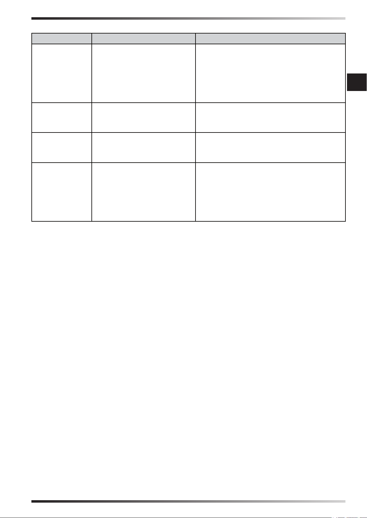
►►6. ANOMALIES DE FONCTIONNEMENT
ANOMALIE CAUSE SOLUTION
L’écran ne
fonctionne pas
Il n’y a pas de
ux d’air ou il
est très bas
Le dispositif ne
répond pas aux
commandes
Le dispositif
perd de l’eau
1. Absence d’alimentation
1a. Contrôler que le dispositif soit relié à
l’alimentation
1b. Contrôler que l’écran soit relié au
câble
1c. Contacter le centre d’assistance
2. Appareillage défectueux
1. Obstruction de prises
d’air
2. Appareillage défectueux
2. Contacter le centre d’assistance
1a. Ôter d’éventuels objets de prise d’air
1b. Contacter le centre d’assistance
2. Contacter le centre d’assistance
1. Appareillage défectueux 1. Contacter le centre d’assistance
1. Le tuyau hydrique fourni
1. Visser le raccord
est desserré
2. Le système de décharge
2. Contacter le centre d’assistance
est sale
3. Le réservoir perd
4. Le panneau dégoutte
3. Contacter le centre d’assistance
4. Contacter le centre d’assistance
fr
Figures and texts of this book are protected by COPYRIGHT.
Page 38
SUMÁRIO PARÁGRAFOS
1... INFORMAÇÕES SOBRE A SEGURANÇA
2... DESEMBALAGEM
3... MONTAGEM E INSTALAÇÃO
(SÓ PARA PESSOAL QUALIFICADO)
4... FUNCIONAMENTO
5... LIMPEZA E MANUTENÇÃO
6... ANOMALIAS DE FUNCIONAMENTO
pt
IMPORTANTE: LER E COMPREENDER ESTE MANUAL OPERATIVO ANTES DE
EFETUAR A MONTAGEM, A COLOCAÇÃO EM SERVIÇO OU A MANUTENÇÃO
DESTE RESFRIADOR. O USO ERRADO DO RESFRIADOR PODE CAUSAR
LESÕES GRAVES OU FATAIS. CONSERVE ESTE MANUAL PARA FUTURAS
CONSULTAS.
►►1. INFORMAÇÕES SOBRE A
SEGURANÇA
IMPORTANTE: Este aparelho não
é adequado para o uso de pessoas
(inclusive crianças) com capacidades
físicas, sensoriais e mentais
reduzidas, ou inexperientes, a menos
que sejam supervisionadas por uma
pessoa responsável pela segurança
destas mesmas pessoas. As crianças
devem ser vigiadas para que não
brinquem com o aparelho.
►1.1. Durante a instalação, a conexão
às redes elétrica e hídrica, o uso e
a manutenção do resfriador, seguir
todas as normas locais e a legislação
vigente.
►1.2. A instalação, a regulação e
a manutenção do resfriador são
operações que só devem ser
realizadas por pessoal qualicado.
►1.3. Usar este aparelho para resfriar,
humidicar, ventilar ou eliminar a
poeira.
►1.4. A m de evitar o risco de
incêndio ou de lesões graves, instalar
o resfriador a uma distância de
segurança de fontes de calor (lareiras,
fogo, etc.), de centelhas (soldadoras,
quadros elétricos, etc.) ou de fumos
de combustão (exaustores, condutas
de evacuação de fumos, etc.)
►1.5. A conexão elétrica imprópria ou a
instalação imprópria podem provocar
risco ou graves avarias.
►1.6. Antes de fazer qualquer operação,
vericar se o resfriador, o cabo de
alimentação, o painel de comandos,
etc. estão perfeitamente secos a m
de prevenir qualquer risco ou graves
avarias (nunca operar com as mãos
molhadas).
►1.7. Instalar apenas em ambiente
externo.
►1.8. O resfriador deve ser instalado
sobre uma estrutura estável e
nivelada de modo a evitar qualquer
risco (a estrutura e as buchas devem
ser adequados para suportar o peso
do aparelho).
►1.9. A distância mínima de segurança
aconselhada entre o resfriador e as
paredes ou outros objetos é de 0,5 m.
►1.10. Deve-se preparar uma saída
de 0,8 m
2
para cada 3.600 m3/h de ar
fornecido pelo resfriador (garantir
sempre uma troca de ar adequada
dentro do ambiente resfriado). Em
caso de ventilação forçada do ar,
a quantidade extraída deverá ser
inferior a 85% do ar introduzido.
A ventilação forçada pode ser
associada à ventilação natural.
Figures and texts of this book are protected by COPYRIGHT.
Page 39

►1.11. Alimentar o resfriador só a com
tensão e a frequência especicada
na placa de dados, utilizando cabos
de secção adequada (a tensão
de alimentação não deve ter uma
variação superior a ± 5% em relação
ao valor indicado na placa de dados).
►1.12. Assegurar-se de que o resfriador
seja corretamente ligado à terra.
►1.13. Assegurar-se de que no
momento da conexão elétrica sejam
respeitadas as conexões fase-neutro.
É aconselhável a utilização de um
interruptor diferencial de tipo 2P 10A.
►1.14. O resfriador pode suportar
uma pressão máxima de entrada
de água de 3 Bar. Se a pressão do
fornecimento hídrico for superior,
será necessário instalar um redutor
de pressão.
►1.15. Abastecer o reservatório do
resfriador somente com água limpa.
►1.16. É aconselhável usar uma
cobertura horizontal para proteger
contra os agentes atmosféricos a m
de preservar o resfriador ao longo do
tempo.
►1.17. É proibido fazer qualquer
modicação, adulteração, regulação
do resfriador e da rede elétrica ou
hídrica após a instalação se não for
executada por pessoal qualicado.
►1.18. Não obstruir, nem mesmo
parcialmente, as tomadas de ar do
resfriador, a m de prevenir qualquer
risco.
►1.19. A m de evitar graves avarias,
evitar que poeira, sujidades ou outros
materiais entrem em contacto com o
resfriador.
►1.20. É aconselhável utilizar o
resfriador com temperaturas do
ambiente compreendidas entre 18°C
e 45°C e com temperatura da água
inferior a 45°C.
►1.21. A m de evitar graves avarias,
quando as temperaturas atingirem
aproximadamente < 2°C, esvaziar
completamente o reservatório e os
tubos que fornecem água para o
resfriador.
►1.22. Desconectar a alimentação
elétrica ao manusear ou fazer a
manutenção no resfriador (utilizar
proteções pessoais a m de prevenir
qualquer risco).
►1.23. Se o cabo de alimentação estiver
danicado, deverá ser substituído
em um centro de assistência técnica,
para prevenir qualquer tipo de risco.
►1.24. Proteger o cabo de alimentação
de potenciais danos decorrentes do
movimento de veículos, transeuntes,
agentes atmosféricos e fontes de
calor.
►1.25. Em caso de maus
funcionamentos do resfriador,
desconectar a alimentação elétrica
e contactar o centro de assistência
técnica.
►1.26. Desconectar o resfriador
da alimentação quando não for
utilizado por um período de médio a
prolongado.
►1.27. Esvaziar frequentemente o
reservatório do resfriador a m de
evitar riscos de estagnação de água.
►►2. DESEMBALAGEM
(Fig. 1)
IMPORTANTE: É ABSOLUTAMENTE
PROIBIDO EMPILHAR DUAS OU MAIS
UNIDADES DE APARELHOS.
►2.1. Remover todos os materiais de
embalagem utilizados para embalar e
enviar o aparelho e eliminá-los segundo
as normas em vigor.
►2.2. Extrair todos os artigos da
embalagem.
►2.3. Controlar eventuais danos
sofridos durante o transporte. Se o
aparelho estiver danicado, informar
imediatamente o concessionário onde
foi adquirido.
pt
Figures and texts of this book are protected by COPYRIGHT.
Page 40

►►3. MONTAGEM E
INSTALAÇÃO (SÓ PARA PESSOAL
QUALIFICADO)
NOTA: PARA ACEDER ÀS PARTES
INTERNAS DO RESFRIADOR, REMOVER
OS PARAFUSOS E OS PAINÉIS
EVAPORADORES, POSICIONÁ-LOS
NAS LATERAIS DO APARELHO (Fig. 2).
pt
►3.1. MOVIMENTAÇÃO
Movimentar o resfriador com o máximo
cuidado, deslocando-o em posição
horizontal.
►3.2. PRÉ-INSTALAÇÃO E MÉTODO
DE INSTALAÇÃO
(Fig. 3)
Durante a instalação, a conexão às redes
elétrica e hídrica, o uso e a manutenção
do resfriador, seguir todas as normas
locais e a legislação vigente.
►3.2.1. O resfriador deve ser instalado
sobre uma estrutura estável e nivelada de
modo a evitar qualquer risco (a estrutura
e as buchas devem ser adequados para
suportar o peso do aparelho).
►3.2.2. Instalar o resfriador em áreas
bem ventiladas.
►3.2.3. O resfriador só pode ser instalado
em ambiente externo (no teto ou na
parede).
►3.2.4. Instalar o resfriador longe de
lareiras, fontes de calor e possíveis
centelhas a m de evitar graves danos.
►3.3. MÉTODO DE CANALIZAÇÃO
Conectando um tubo ao resfriador, é
possível transportar o ar que sai para
onde é necessário resfriar.
É importante que todo o tubo de
canalização seja projetado e estruturado
de modo correto.
►3.3.1. Utilizar tubos de secção adequada
(a velocidade média do ar dentro do tubo
é de 3-6 m/s).
►3.3.2. A canalização deve ser curta o
quanto possível.
►3.3.3. As tubagens devem ser instaladas
no máximo a 4 m de altura do chão.
►3.3.4. Evitar curvas em cotovelo do
tubo.
►3.3.5. O comprimento máximo do tubo
deve ser de 20 m.
►3.3.6. Devem ser instaladas no máximo
quatro reduções no tubo.
►3.3.7. As junções do tubo devem ser
exíveis.
►3.3.8. Evitar ramicar o uxo do ar em
vários tubos e tubos secundários.
NOTA: É ACONSELHÁVEL UTILIZAR
TUBOS DE CHAPA ZINCADA, PLÁSTICO
OU DE FIBRA DE VIDRO.
►3.4. LIGAÇÃO À REDE ELÉTRICA
IMPORTANTE: A REALIZAÇÃO DA
LINHA DE ALIMENTAÇÃO ELÉTRICA E
DA LIGAÇÃO DEVE SER FEITA POR UM
TÉCNICO HABILITADO, UTILIZANDO
DISPOSITIVOS E INSTRUMENTOS
ADEQUADOS, CONFORME A
REGULAMENTAÇÃO NACIONAL E DE
ACORDO COM AS NORMAS VIGENTES.
►3.4.1. Ao remover os parafusos do
resfriador, tem-se acesso ao interior do
aparelho (Fig. 2).
►3.4.2. Passar os cabos elétricos (cabo
de alimentação e cabo do painel de
comandos) através do orifício situado
perto do painel elétrico (Fig. 4).
►3.4.3. Conectar e alimentar o resfriador
só com a tensão e a frequência especicada
na placa dos dados e com parafusos
de secção adequada (respeitando as
polaridades fase-neutro).
►3.4.4. Para o correto funcionamento
é fundamental conectar corretamente a
ligação à terra ao resfriador.
►3.4.5. Conectar o painel de comandos
através do conector especíco (Fig. 5).
Figures and texts of this book are protected by COPYRIGHT.
Page 41

NOTA: É ACONSELHÁVEL A
UTILIZAÇÃO DE UM INTERRUPTOR
DIFERENCIAL DE TIPO 2P 10A.
►3.5. INSTALAÇÃO DA VÁLVULA DE
DESCARGA
(Fig. 6)
Na base do resfriador, para drenar a água
do reservatório, o resfriador é dotado de
uma válvula de descarga.
A válvula de descarga, no momento da
compra, situa-se junto ao material que
acompanha o equipamento.
Para instalar a válvula de descarga é
necessário:
►3.5.1. Remover a porca instalada na
base da válvula.
►3.5.2. Inserir a válvula no respetivo
alojamento (posicionado na base do
resfriador).
►3.5.3. Reaparafusar a porca na válvula.
►3.6. LIGAÇÃO À REDE HÍDRICA
(Fig. 7)
IMPORTANTE: ALIMENTAR O
RESFRIADOR SÓ COM ÁGUA LIMPA.
IMPORTANTE: O RESFRIADOR PODE
SUPORTAR UMA PRESSÃO MÁXIMA
DE ENTRADA DE ÁGUA DE 3 BAR.
AS TUBAGENS E AS CONEXÕES
UTILIZADAS PARA A ALIMENTAÇÃO
HÍDRICA DEVEM TER SECÇÃO E
ESTRUTURA ADEQUADAS (SE A
PRESSÃO DA REDE HÍDRICA FOR
ELEVADA, SERÁ ACONSELHÁVEL
USAR REDUTOR DE PRESSÃO E UMA
TUBAGEM COM MALHA METÁLICA).
►3.6.1. Conectar o resfriador à rede
hídrica através da conexão roscada.
►3.6.2. Vericar se não apresentam
fugas de água do circuito antes de colocar
em serviço.
►3.7. CONFIGURAÇÃO BÁSICA
(Fig. 8)
IMPORTANTE: A CONFIGURAÇÃO
BÁSICA DO RESFRIADOR DEVE
SER FEITA ATRAVÉS DO PAINEL DE
CONTROLO. A CONFIGURAÇÃO DEVE
SER FEITA COM O RESFRIADOR
DESLIGADO, MAS ALIMENTADO PELA
REDE ELÉTRICA.
pt
►DRAIN: (Manter pressionado durante
alguns segundos o botão DRAIN):
Entra-se no submenu que permite denir
a cada quantas horas o resfriador, de
modo automático, deve descarregar
a água do reservatório (congurado
com o valor “0”, o reservatório nunca é
descarregado de modo automático).
►VENTOINHA: (Manter pressionado
durante alguns segundos o botão
VENTOINHA): Acede-se ao submenu
que permite denir o sentido de rotação
da ventoinha [(0= horário, para introduzir
ar no ambiente) (1= anti-horário, para
subtrair ar do ambiente)].
►►4. FUNCIONAMENTO
ADVERTÊNCIA: Ler atentamente
as ”INFORMAÇÕES SOBRE A
SEGURANÇA” antes de ligar o
resfriador.
ADVERTÊNCIA: Utilizar somente
água limpa para evitar avarias ou
outras anomalias.
ADVERTÊNCIA: Verique a correta
instalação à terra do seu sistema
elétrico. A ligação à rede elétrica deve
ser feita de acordo com as normas
nacionais em vigor. Alimentar o
aparelho somente com a tensão e a
frequência especicadas na placa de
dados.
Figures and texts of this book are protected by COPYRIGHT.
Page 42

IMPORTANTE: O resfriador é dotado
de descarga de água posicionada
na base do aparelho. Conforme
a conguração, o resfriador vai
descarregar completamente a água
do reservatório a m de evitar
estagnação de água. De qualquer
modo, é aconselhável descarregar a
água do reservatório frequentemente.
Durante o inverno ou em caso de
pt
período prolongado de inatividade,
esvaziar completamente o circuito e
o reservatório de água.
NOTA: É aconselhável descarregar a
água do reservatório antes de cada
desligamento.
►4.1. PAINEL DE CONTROLO E
FUNÇÕES
(Fig. 9)
►ON/OFF: Permite ligar ou desligar o
resfriador.
►SETA ↑↓: Permite aumentar ou diminuir
a velocidade de ventilação.
►COOL: Permite ativar ou desativar a
modalidade de arrefecimento.
►VENTOINHA: Permite ativar a
modalidade apenas ventilação.
►SWING (Predisposição): É a
predisposição que permite ativar ou
desativar a oscilação automática das
aletas para direcionar o uxo de ar.
►DRAIN: Permite descarregar a água do
reservatório.
NOTA: Quando no ecrã do painel
de controlo aparece o ícone
“RESERVATÓRIO” (a piscar)
acompanhado por um sinal acústico,
signica que o reservatório está vazio
e deve ser enchido novamente para
reativar a função COOL.
►4.2. TELECOMANDO REMOTO E
FUNÇÕES
(Fig. 10)
►ON/OFF: Permite ligar ou desligar o
resfriador.
►SETA ↑↓: Permite aumentar ou diminuir
a velocidade de ventilação.
►COOL: Permite ativar ou desativar a
modalidade de arrefecimento.
►VENT: Permite ativar a modalidade
apenas ventilação.
►SWING (Predisposição): É a
predisposição que permite ativar ou
desativar a oscilação automática das
aletas para direcionar o uxo de ar.
►DRAIN: Permite descarregar a água do
reservatório.
►LIGHT: Permite acender a luz no ecrã.
►HOUR e MINUTE: Permite regular a
hora do telecomando.
►4.3. DESLIGAMENTO
►4.3.1. Descarregar a água do
reservatório com a função dedicada
DRAIN.
►4.3.2. Pressionar o botão ON/OFF
para desligar o resfriador (a ventilação
continua por alguns minutos para permitir
a secagem dos painéis evaporadores).
►4.3.3. Quando o resfriador não estiver
em uso, desconectar a alimentação
elétrica e a alimentação hídrica.
►►5. LIMPEZA E MANUTENÇÃO
ADVERTÊNCIA: ANTES DE EFETUAR
QUALQUER OPERAÇÃO DE
MANUTENÇÃO OU REPARAÇÃO,
DESCONECTAR A ALIMENTAÇÃO
ELÉTRICA E A ALIMENTAÇÃO
HÍDRICA.
Conforme o ambiente no qual o aparelho
é utilizado, o pó, a sujidade, etc. podem
inuenciar o desempenho do resfriador.
Por isso, é aconselhável limpar com um
pano macio (é proibido limpar com um jato
de água de alta pressão) a parte externa
do resfriador, removendo eventuais
obstruções das tomadas de ar.
Figures and texts of this book are protected by COPYRIGHT.
Page 43

►►6. ANOMALIAS DE FUNCIONAMENTO
ANOMALIA CAUSA SOLUÇÃO
O ecrã não
funciona
Não há uxo
de ar ou é
muito baixo
O dispositivo
não responde
aos comandos
O dispositivo
perde água
1. Falta de alimentação
2. Equipamento com
defeito
1. Obstrução das tomadas
de ar
2. Equipamento com
defeito
1. Equipamento com
defeito
1. O tubo de fornecimento
hídrico está frouxo
2. A descarga de água está
suja
3. O reservatório apresenta
fugas
4. O painel goteja
1a. Controlar se o dispositivo está
conectado à alimentação
1b. Controlar se o ecrã está conectado
ao cabo
1c. Contactar o centro de assistência
2. Contactar o centro de assistência
1a. Remover eventuais objetos da
tomada de ar
1b. Contactar o centro de assistência
2. Contactar o centro de assistência
1. Contactar o centro de assistência
1. Aparafusar a conexão
2. Contactar o centro de assistência
3. Contactar o centro de assistência
4. Contactar o centro de assistência
pt
Figures and texts of this book are protected by COPYRIGHT.
Page 44

SPIS TREŚCI PARAGRAFÓW
1... INFORMACJE DOTYCZĄCE BEZPIECZEŃSTWA
2... ROZPAKOWYWANIE
3... MONTAŻ I INSTALACJA
(TYLKO DLA WYKWALIFIKOWANEGO PERSONELU)
4... DZIAŁANIE
5... CZYSZCZENIE I KONSERWACJA
6... NIEPRAWIDŁOWOŚCI DZIAŁANIA
WAŻNE: PRZED PRZYSTĄPIENIEM DO MONTAŻU, URUCHOMIENIA LUB
KONSERWACJI NIENIEJSZEGO URZĄDZENIA NALEŻY UWAŻNIE PRZECZYTAĆ
I ZROZUMIEĆ PONIŻSZĄ INSTRUKCJĘ. NIEPRAWIDŁOWE UŻYCIE URZĄDZENIA
MOŻE BYĆ PRZYCZYNĄ POWAŻNYCH OBRAŻEŃ. NINIEJSZĄ INSTRUKCJĘ
NALEŻY ZACHOWAĆ NA PRZYSZŁOŚĆ.
►►1. INFORMACJE DOTYCZĄCE
pl
BEZPIECZEŃSTWA
WAŻNE: Niniejsze urządzenie
nie jest przystosowane do używania
przez osoby (łącznie z dziećmi)
o ograniczonych zdolnościach
zycznych, sensorycznych i
psychicznych lub przez osoby
niedoświadczone, chyba że pod
nadzorem osoby odpowiedzialnej
za ich bezpieczeństwo. Należy
kontrolować dzieci, aby mieć pewność,
że nie bawią się urządzeniem.
►1.1. Podczas instalacji, podłączania
elektrycznego, hydraulicznego, obsługi
i konserwacji urządzenia należy
przestrzegać wszystkich lokalnych
przepisów i obowiązujących norm.
►1.2. Instalacja, regulacja, konserwacja
urządzenia musi być wykonywana
wyłącznie przez wykwalikowany
personel.
►1.3. Niniejszego urządzenia należy
używać do chłodzenia, nawilżania,
wentylowania oraz usuwania kurzu
z powietrza ( poprzez obniżenie
temperatury ).
►1.4. By uniknąć ryzyka pożaru lub
poważnych obrażeń należy zainstalować
urządzenie w bezpiecznej odległości od
źródeł ciepła (kominy, płomień, itp.), od
iskier (spawarki, rozdzielnie elektryczne,
itp.) lub od dymów spalinowych (okapy,
kanały dymowe, itp.).
►1.5. Nieprawidłowe podłączenie
elektryczne lub niewłaściwa instalacja
może spowodować zagrożenie zdrowia
lub poważne uszkodzenia.
►1.6. Przed wykonaniem jakiejkolwiek
czynności, należy upewnić się,
że urządzenie, kabel zasilania,
panel sterowania, itp. są dokładnie
osuszone, aby zapobiec zagrożeniom
lub poważnym uszkodzeniom (nie
obsługiwać urządzenia mokrymi
dłońmi).
►1.7. Instalować wyłącznie na zewnątrz.
►1.8. Urządzenie musi być zainstalowane
na stabilnym i wypoziomowanym
podłożu (pion instalacyjny i kołki
muszą być odpowiednio dobrane do
podtrzymania ciężaru urządzenia).
►1.9. Minimalna, zalecana odległość
bezpieczeństwa między urządzeniem
a ścianami lub innymi przedmiotami
wynosi 0,5m.
►1.10. Należy przygotować otwór
wielkości 0,8 m2 na każde 3.600 m3/h
powietrza dostarczanego do urządzenia
(należy zawsze zagwarantować wymianę
powietrza wewnątrz chłodzonego
środowiska). W przypadku wymuszonej
wentylacji powietrza, ilość powietrza
wyciąganego musi być niższa niż 85%
Figures and texts of this book are protected by COPYRIGHT.
Page 45

powietrza wprowadzanego. Wymuszona
wentylacja może być połączona z
wentylacją naturalną.
►1.11. Urządzenie nalezy zasilać tylko
wartościami napięcia i częstotliwości
wskazanymi na tabliczce znamionowej,
używając kabli o odpowiednim przekroju
(napięcie zasilania nie może zmieniać
się o więcej niż ± 5% względem wartości
wskazanej na tabliczce znamionowej).
►1.12. Upewnić się, że urządzenie jest
odpowiednio podłączone do przewodu
ochronnego.
►1.13. Upewnić się, że w momencie
podłączenia elektrycznego
przestrzegane są połączenia fazaneutralny. Zaleca się używanie
wyłącznika różnicowo-nadprądowego
typu 2P 10A.
►1.14. Maksymalne ciśnienie wejścia
wody, które obsługuje urządzenie
wynosi 3 bary. Jeśli ciśnienie instalacji
wodnej jest wyższe, należy zainstalować
reduktor ciśnienia.
►1.15. Zbiornik napełniać tylko czystą
wodą.
►1.16. Zaleca się używanie specjalnego
pokrycia, chroniącego przed działaniem
czynników atmosferycznych, aby
zapewnić trwałość urządzenia
chłodzącego przez długi czas.
►1.17. Zabrania się jakiegokolwiek
modykowania, manipulowania,
regulowania urządzenia i sieci
elektrycznej lub wodnej po instalacji,
jeśli nie są one wykonywane przez
wykwalikowany personel.
►1.18. Nie zasłaniać, nawet częściowo,
wlotów powietrza.
►1.19. Aby uniknąć poważnych usterek,
unikać kontaktu kurzu, brudu i innych
materiałów z urządzeniem chłodzącym.
►1.20. Zaleca się używanie urządzenia
chłodzącego przy temperaturze
środowiska zawartej między 18°C i 45°C
i przy temperaturze wody niższej od
45°C.
►1.21. By uniknąć poważnych usterek,
kiedy temperatury obniżą się do około <
2°C, należy całkowicie opróżnić zbiornik
i przewody instalacji wodnej do której
podłączone jest urządzenie.
►1.22. Nie należy nigdy przemieszczać,
obsługiwać uzupełniać lub wykonywać
konserwacji podłączonego do zasilania
elektrycznego lub włączonego
urządzenia. (używać środków
ochrony indywidualnej, aby zapobiec
jakiemukolwiek zagrożeniu).
►1.23. W celu uniknięcia wszelkiego
ryzyka, uszkodzony kabel zasilający
musi być wymieniony przez
autoryzowany punkt serwisowy.
►1.24. Chronić kabel zasilania przed
potencjalnymi uszkodzeniami
związanymi z poruszaniem się pojazdów,
pieszych, działaniem czynników
atmosferycznych i źródeł ciepła.
►1.25. W przypadku stwierdzenia
nieprawidłowości działania urządzenia,
odłączyć zasilanie elektryczne i
skontaktować się z centrum pomocy
technicznej.
pl
►1.26. Odłączyć urządzenie od zasilania,
kiedy nie jest ono używane przez
dłuższy okres czasu.
►1.27. Często opróżniać zbiornik
urządzenia chłodzącego, tak aby
uniknąć stagnacji wody.
►►2. ROZPAKOWYWANIE
(Rys. 1)
WAŻNE: SUROWO ZABRANIA SIĘ
USTAWIANIA NA SOBIE URZĄDZEŃ.
►2.1. Zdjąć opakowanie użyte do
zapakowania i wysłania produktu i
zutylizować je zgodnie z obowiązującymi
normami.
►2.2. Wyjąć wszystkie elementy z
opakowania.
►2.3. Sprawdzić, czy występują ewentualne
uszkodzenia powstałe podczas transportu.
Jeśli urządzenie okaże się uszkodzone,
natychmiast poinformować sprzedawcę.
Figures and texts of this book are protected by COPYRIGHT.
Page 46

►►3. MONTAŻ I INSTALACJA
(TYLKO DLA YKWALIFIKOWANEGO
PERSONELU)
UWAGA: BY OTRZYMAĆ DOSTĘP DO
CZĘŚCI WEWNĘTRZNYCH URZĄDZENIA,
NALEŻY WYKRĘCIĆ ŚRUBY I ZDJĄĆ
PANELE EWAPORACYJNE ZNAJDUJĄCE
SIĘ PO BOKACH (Rys. 2).
►3.1. PRZEMIESZCZANIE
W celu zmiany miejsca należy ostrożnie
przestawić urządzenie, przemieszczając je w
pozycji poziomej.
►3.3.2. Przewód kanałowy musi być jak
najkrótszy.
►3.3.3. Przewody rurowe muszą być
zainstalowane na wysokości maksymalnej
4m nad ziemią.
►3.3.4. Unikać tworzenia ostrych zakrętów
na przewodzie.
►3.3.5. Maksymalna długość przewodu
musi wynosić 20m.
►3.3.6. Należy zainstalować maksymalnie
cztery redukcje wewnątrz przewodu.
►3.3.7. Złącza rury muszą być elastyczne.
►3.3.8. Unikać rozgałęziania przepływu
powietrza na większą ilość przewodów i
przewodów pochodnych.
►3.2. INSTALACJA WSTĘPNA I SPOSÓB
INSTALACJI
(Rys. 3)
Podczas instalacji, podłączania elektrycznego,
pl
hydraulicznego, obsługi i konserwacji
urządzenia, przestrzegać wszystkich
lokalnych przepisów i obowiązujących norm.
►3.2.1. Urządzenie chłodzące musi
być zainstalowane na stabilnym i
wypoziomowanym podłożu (pion instalacyjny
i kołki muszą być odpowiednie do
podtrzymania ciężaru urządzenia).
►3.2.2. Urządzenie należy instalować w
miejscach o dobrej wentylacji.
►3.2.3. Urządzenie może być zainstalowane
wyłącznie na zewnątrz (dach lub ściana).
►3.2.4. Urządzenie chłodzące należy
instalować z dala od kominów, źródeł ciepła
i możliwych iskier, aby uniknąć poważnych
szkód.
►3.3. SPOSÓB WYKONANIA KANAŁU
WENTYLACYJNEGO
Podłączając kanał wentylacyjny do
urządzenia, możłiwe jest przetransportowanie
schłodzonego powietrze do docelowo
schładzanego miejsca.
Ważne jest, aby cały kanał został
zaprojektowany i skonstruowany w sposób
poprawny.
►3.3.1. Używać przewodów o odpowiednim
przekroju (średnia prędkość powietrza
wewnątrz przewodu wynosi 3-6 m/s).
UWAGA: ZALECA SIĘ UŻYWANIE
KANAŁÓW Z BLACHY CYNKOWANEJ,
Z TWORZYWA SZTUCZNEGO LUB Z
WŁÓKNA SZKLANEGO.
►3.4. PODŁĄCZENIE DO SIECI
ELEKTRYCZNEJ
WAŻNE: WYKONANIE LINII ZASILANIA
ELEKTRYCZNEGO I PODŁĄCZENIE
MUSZĄ ZOSTAĆ WYKONANE PRZEZ
UPOWAŻNIONEGO TECHNIKA,
UŻYWAJĄCEGO ODPOWIEDNICH
NARZĘDZI I URZĄDZEŃ, ZGODNIE
Z PRZEPISAMI KRAJOWYMI I Z
OBOWIĄZUJĄCYMI NORMAMI.
►3.4.1. Wykręcając śruby mocujące panele
ewaporacyjne otrzymuje się dostęp do części
wewnętrznych urządzenia (Rys. 2).
►3.4.2. Przeciągnąć kable elektryczne
(kabel zasilania i kabel panelu sterowania)
przez otwór znajdujący się w pobliżu panelu
elektrycznego (Rys. 4).
►3.4.3. Podłączyć i włączyć zasilanie
urządzenia wyłącznie z wartościami napięcia
i częstotliwości wskazanymi na tabliczce
znamionowej i kablami o odpowiednim
przekroju (przestrzegając biegunów fazaneutralny).
►3.4.4. Upewnić się, że urządzenie jest
odpowiednio podłączone do przewodu
ochronnego.
►3.4.5. Podłączyć panel sterowania za
pomocą specjalnego łącznika (Rys. 5).
Figures and texts of this book are protected by COPYRIGHT.
Page 47

UWAGA: ZALECA SIĘ UŻYWANIE
WYŁĄCZNIKA RÓŻNICOWONADPRĄDOWEGO TYPU 2P 10A.
►3.5. INSTALACJA ZAWORU
UPUSTOWEGO
(Rys. 6)
Urządzenie chłodzące wyposażone jest w
zawór upustowy do spuszczania wody ze
zbiornika.
Zawór upustowy dostępny jest jako część
wyposażenia.
By zainstalować zawór spustowy, należy:
►3.5.1. Usunąć nakrętkę zainstalowaną na
podstawie zaworu.
►3.5.2. Wprowadzić zawór do stosownego
miejsca osadzenia (znajdującego się na
podstawie urządzenia chłodzącego).
►3.5.3. Ponownie dokręcić nakrętkę na
zaworze.
KONFIGURACJĘ NALEŻY WYKONAĆ
NA URZĄDZENIU CHŁODZĄCYM
ODŁĄCZONYM OD SIECI ELEKTRYCZNEJ.
►DRAIN: (Przytrzymać wciśnięty przez kilka
sekund przycisk DRAIN): Aktywacja menu,
które umożliwia ustawienie co interwałów
czasowych, po których urządzenie
chłodzące w trybie automatycznym musi
opróżnić wodę ze zbiornika (z wartością
„0” zbiornik nigdy nie jest opróżniony
automatycznie).
►WENTYLATOR: (Przytrzymać
wciśnięty przez kilka sekund przycisk
WENTYLATOR): Aktywacja menu, które
umożliwia ustawienie kierunku obracania
wentylatora [(0= zgodnie z ruchem
wskazówek zegara, aby doprowadzić
powietrze do chłodzonego pomieszczenia)
(1= przeciwnie do ruchu wskazówek
zegara, aby zamknąć dopływ powietrza do
pomieszczenia)].
pl
►3.6. PODŁĄCZENIE DO SIECI WODNEJ
(Rys. 7)
WAŻNE: DO URZĄDZENIA CHŁODZĄCEGO
DOPROWADZAĆ WYŁĄCZNIE CZYSTĄ
WODĘ.
WAŻNE: MAKSYMALNE CIŚNENIE
WEJŚCIA WODY, KTÓRE OBSŁUGUJE
URZĄDZENIE CHŁODZĄCE WYNOSI 3
BAR. PRZEWODY RUROWE I ZŁĄCZA
UŻYWANE DO DYSTRUBUCJI WODNEJ
MUSZĄ POSIADAĆ ODPOWIEDNI
PRZEKRÓJ I STRUKTURĘ (JEŚLI
CIŚNIENIE SIECI WODNEJ JEST WYSOKIE,
ZALECA SIĘ UŻYWANIE REDUKTORA
CIŚNIENIA I PRZEWODU RUROWEGO Z
METALOWYM OGNIWEM).
►3.6.1. Podłączyć urządzenie chłodzące
do sieci wodnej za pomocą gwintowanego
złącza.
►3.6.2. Przed włączeniem sprawdzić czy nie
są obecne wycieki wody z obwodu.
►►4. DZIAŁANIE
OSTRZEŻENIE: Uważnie przeczytać
„INFORMACJE DOTYCZĄCE
BEZPIECZEŃSTWA” przed
otrzymaniem dostępu do urządzenia
chłodzącego.
OSTRZEŻENIE: Używać jedynie
czystej wody, aby uniknąć usterek lub
innych nieprawidłowości.
OSTRZEŻENIE: Sprawdzić
poprawność uziemienia Państwa
instalacji elektrycznej. Podłączenie
do sieci elektrycznej musi zostać
wykonane zgodnie z obowiązującymi
normami krajowymi. Zasilać
urządzenie jedynie wartościami
napięcia i częstotliwości podanymi na
tabliczce znamionowej.
►3.7. KONFIGURACJA PODSTAWOWA
(Rys. 8)
WAŻNE: KONFIGURACJA PODSTAWOWA
URZĄDZENIA CHŁODZĄCEGO MUSI BYĆ
WYKONANA Z PANELU STEROWANIA.
Figures and texts of this book are protected by COPYRIGHT.
Page 48

WAŻNE: Urządzenie wyposażone jest
w zawór spustowy wody, znajdujący
się w podstawie urządzenia. W
zależności od ustawień, urządzenie
całkowicie opróżni wodę ze zbiornika.
Zaleca się częste spuszczanie wody ze
zbiornika w celu uniknięcia stagnacji
wody.
Podczas okresu zimowego lub w
przypadku nie korzystania z urządzenia,
należy całkowicie opróżnić instalację
wodną i zbiornik wody.
Podczas okresu zimowego lub
w przypadku długiego okresu
nieużywania, całkowicie opróżnić
obwód i zbiornik wody.
UWAGA: Zaleca się rozładowanie
wody ze zbiornika przed każdym
pl
wyłączeniem.
►4.1. PANEL STEROWANIA I FUNKCJE
(Rys. 9)
►ON/OFF: Umożliwia włączenie lub
wyłączenie urządzenia.
►STRZAŁKA ↑↓: Umożliwia zwiększenie lub
zmniejszenie prędkości wentylacji.
►COOL: Umożliwia włączenie lub wyłączenie
trybu chłodzenia.
►WENTYLATOR: Umożliwia aktywację tylko
trybu wentylacji.
►SWING: Umożliwia włączenie lub
wyłączenie silnika regulacji kierunku
nawiewu powietrza.
►DRAIN: Umożliwia opróżnienie wody ze
zbiornika.
UWAGA: Kiedy na wyświetlaczu
panelu sterowania pojawi się ikona
„ZBIORNIK” (migając), wraz z
brzęczykiem, oznacza to, że zbiornik
jest pusty i że należy go ponownie
uzupełnić, aby włączyć funkcję COOL.
►4.2. PILOT ZDALNEGO STEROWANIA I
FUNKCJE
(Rys. 10)
►ON/OFF: Umożliwia włączenie lub
wyłączenie urządzenia.
►STRZAŁKA ↑↓: Umożliwia zwiększenie lub
zmniejszenie prędkości wentylacji.
►COOL: Umożliwia włączenie lub wyłączenie
trybu chłodzenia.
►VENT: Umożliwia aktywację tylko trybu
wentylacji.
►SWING: Umożliwia włączenie lub
wyłączenie silnika regulacji kierunku
nawiewu powietrza.
►DRAIN: Umożliwia opróżnienie wody ze
zbiornika.
►LIGHT: Umożliwia włączenie podświetlenia
wyświetlacza.
►HOUR i MINUTE: Umożliwia ustawienie
czasu pracy urządzenia.
►4.3. WYŁĄCZANIE
►4.3.1. Rozładowanie wody ze zbiornika za
pomocą stosownej funkcji DRAIN.
►4.3.2. Nacisnąć na przycisk ON/OFF,
aby wyłączyć urządzenie chłodzące
(wentylacja pozostaje włączona przez kilka
minut, aby umożliwić wysuszenie panelom
ewaporacyjnym).
►4.3.3. Kiedy urządzenie nie jest używane,
odłączyć zasilanie elektryczne i instalację
hydrauliczną.
►►5. CZYSZCZENIE I
KONSERWACJA
OSTRZEŻENIE: PRZED WYKONANIEM
JAKIEJKOLWIEK KONSERWACJI
LUB NAPRAWY, NALEŻY ODŁĄCZYĆ
ZASILANIE ELEKTRYCZNE I
DYSTRYBUCJĘ WODY.
W zależności od środowiska, w którym
urządzenie będzie używane, pył i brud
mogą wpływać na wydajność urządzenia
chłodzącego. Zaleca się zatem oczyszczenie
za pomocą miękkiej ścierki (surowo zabrania
się czyszczenia za pomocą strumienia wody
pod wysokim ciśnieniem) części zewnętrznej
urządzenia chłodzącego, usuwając
ewentualne zablokowanie wlotów powietrza.
Figures and texts of this book are protected by COPYRIGHT.
Page 49
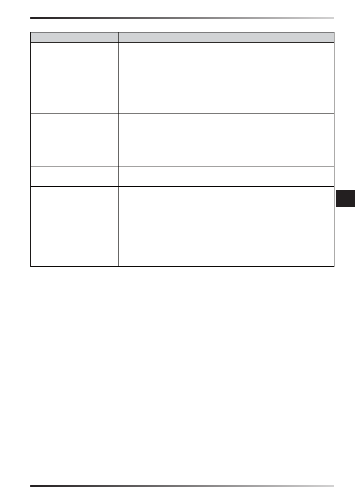
►►6. NIEPRAWIDŁOWOŚCI DZIAŁANIA
NIEPRAWIDŁOWOŚĆ PRZYCZYNA ROZWIĄZANIE
Wyświetlacz nie działa 1. Brak zasilania
2. Wadliwość
urządzenia
Brak przepływu powietrza
lub niski przepływ
1. Zablokowanie wlotów
powietrza
powietrza
2. Wadliwość
urządzenia
Urządzenie nie
odpowiada na polecenia
Wyciek wody z
urządzenia
1. Wadliwość
urządzenia
1. Rura dystrybucji
wodnej jest
poluzowana
2. Sprust wody jest
brudne
3. Wyciek wody ze
zbiornika
4. Wyciek wody z
panelu
1a. Sprawdzić czy urządzenie zostało
podłączone do zasilania
1b. Sprawdzić czy wyświetlacz jest
podłączony do kabla
1c. Skontaktować się z centrum
serwisowym
2. Skontaktować się z centrum
serwisowym
1a. Usunąć ewentualne przeszkody na
wlocie powietrza
1b. Skontaktować się z centrum
serwisowym
2. Skontaktować się z centrum
serwisowym
1. Skontaktować się z centrum
serwisowym
1. Dokręcić złącze
pl
2. Skontaktować się z centrum
serwisowym
3. Skontaktować się z centrum
serwisowym
4. Skontaktować się z centrum
serwisowym
Figures and texts of this book are protected by COPYRIGHT.
Page 50

PARAGRAF İÇERİĞİ
1... GÜVENLİK HAKKINDA BİLGİLER
2... AMBALAJ AÇMA
3... MONTAJ VE KURULUM
(SADECE KALİFİYE PERSONEL İÇİN)
4... İŞLEYİŞ
5... TEMİZLİK VE BAKIM
6... İŞLEYİŞ ANORMALLİĞİ
ÖNEMLİ: BU SOĞUTUCUNUN KURULUMUNU, İŞLEME ALINMASINI VEYA
BAKIMINI GERÇEKLEŞTİRMEDEN ÖNCE BU İŞLETİM KILAVUZUNU OKUYUN
VE ANLAYIN. SOĞUTUCUNUN HATALI KULLANIMI CİDDİ VEYA ÖLÜMCÜL
YARALANMALARA NEDEN OLABİLİR. BU KILAVUZU GELECEKTE REFERANS
AMACIYLA SAKLAYIN.
►►1. GÜVENLİK HAKKINDA
BİLGİLER
ÖNEMLİ: Bu, ziksel, duyusal
ve zihinsel engelleri olan kişiler
(çocuklar dahil) veya güvenlikleri için
sorumlu bir kişi tarafından denetim
altında olmadıkları sürece uzman
olmayan kişiler tarafından kullanıma
uygun değildir. Çocukların cihaz ile
tr
oynamadığından emin olmak için
çocuklar kontrol edilmelidir.
►1.1. Kurulum, elektrik bağlantısı, su
bağlantısı, soğutucunun kullanımı
ve bakım sırasında tüm yürürlükteki
düzenlemelere ve lokal kurallara
dikkat edin.
►1.2. Soğutucunun kurulumu,
ayarlanması ve bakımı sadece
kaliye personel tarafından
yapılmalıdır.
►1.3. Bu cihazı sadece soğutmak,
nemlendirmek, havalandırmak veya
tozu temizlemek için kullanın.
►1.4. Yangın veya ciddi yaralanma
riskini önlemek için soğutucuyu ısı
kaynaklarından (baca, alev, vb.),
kıvılcımlardan (kaynak makinesi,
elektrik panoları, vb.) veya yanma
dumanları (davlumbazlar, duman
bacaları, vb) güvenlik mesafesine
kurulmalıdır.
►1.5. Uygunsuz elektrik bağlantısı
veya uygunsuz kurulum riske veya
ciddi arızalara neden olabilir.
►1.6. Bu işlemi gerçekleştirmeden
önce, soğutucunun, besleme
kablosunun, kumanda panelinin,
vb..her türlü riski veya ciddi arızaları
önlemek için mükemmel şekilde
kuru olduğundan emin olun (asla
ıslak ellerle işlem yapmayın).
►1.7. Sadece dış alana kurun.
►1.8. Soğutucu, her türlü riski
önleyecek şekilde sabit veya
hizalanmış bir yapı üzerine
kurulmalıdır (yapı ve dübeller
teçhizatın ağırlığını desteklemeye
uygun şekilde olmalıdır).
►1.9. Soğutucu ve duvarlar veya
diğer cisimler arasında bulunması
gereken önerilen minimum güvenlik
mesafesi 0,5 m.
►1.10. Soğutucuyla verilen 0,8
2
m
bir çıkış 3.600 m3/h hava
için sağlanmalıdır (her zaman
soğutulan ortamın içinde
hava değişimini garanti edin).
Havanın zorla havalandırılması
durumunda, çıkartılan miktar girilen
Figures and texts of this book are protected by COPYRIGHT.
Page 51
havanın %85 altında olmalıdır.
Zorlanan havalandırma, doğal
havalandırmayla eşleştirilebilir.
►1.11. Soğutucuyu sadece veri
levhasında belirtilen gerilim
ve frekans ile uygun seksiyon
kablolarını kullanarak besleyin
(besleme gerilimi veri levhasında
belirtilen değere göre ± 5% büyük
olarak çeşitlilik göstermelidir.
►1.12. Soğutucunun uygun şekilde
yere bağlandığından emin olun.
►1.13. Elektrik bağlantısı anında faz-
nötr bağlantısına uyulduğundan
emin olun. 2P 10A türünde
diferansiyel bir şalter kullanımı
önerilir.
►1.14. Soğutucu 3 Bar su
girişi maksimum bir basıncı
destekleyebilir. Su tedarik
basıncının büyük olursa eğer, bir
basınç redüktörü kurmak gereklidir.
►1.15. Soğutucu deposunu sadece
temiz su ile doldurun.
►1.16. Zaman içinde soğutucuyu
korumak için atmosfer olaylarının
korumasında yatay örtünün
kullanımı tavsiye edilir.
►1.17. Kaliye personel tarafından
gerçekleştirilmiyorsa eğer,
kurulumdan sonra elektrik ve
su şebekesinin ve soğutucunun
her türlü değişimi, kurcalaması,
ayarlaması yasaktır.
►1.18. Her riski önleyecek şekilde
soğutucunun hava prizlerini kısmen
de olsa engellemeyin.
►1.19. Ciddi arızaları önlemek için,
tozun, kirin ve diğer malzemelerin
soğutucu ile temas etmesini önleyin.
►1.20. Soğutucu 18°C ve 45°C
arasında ortam sıcaklığı ve 45°C
altında su sıcaklığı ile kullanmak
tavsiye edilir.
►1.21. Ciddi arızaları önlemek için,
sıcaklıklar yaklaşık olarak < 2°C
indiği zaman, depoyu ve soğutucuya
su taşıyan boruları tamamen
boşaltın.
►1.22. Soğutucu kullanıldığında veya
bakım yapıldığında elektrik güç
beslemesini kesin (her riski önlemek
için kişisel korumalar kullanın).
►1.23. Besleme kablosu hasarlıysa,
her riski önleyecek şekilde
teknik servis merkezi tarafından
değiştirilmelidir.
►1.24. Araçların hareketinden,
atmosfer olaylarından ve ısı
kaynaklarından kaynaklanan
potansiyel besleme kablosunu
koruyun.
►1.25. Soğutucunun hatalı çalışması
durumunda, elektrik beslemesini
kesin ve teknik servis merkezi ile
iletişime geçin.
►1.26. Uzun süre boyunca
soğutucunun kullanılmaması
durumunda, besleme kaynaklarını
kesin.
►1.27. Suyun hareketsizliğini önlemek
için soğutucunun deposunu sıklıkla
boşaltın.
tr
►►2. AMBALAJ AÇMA
(Şek. 1)
ÖNEMLİ: CİHAZLARI İKİ VEYA DAHA
FAZLA ÜNİTEYE YÜKLENMESİ
KESİNLİKLE YASAKTIR.
►2.1. Cihazı paketlemek ve göndermek
için kullanılan tüm ambalajlama
malzemelerini çıkartın ve yürürlükteki
yönetmeliklere göre yok edin.
►2.2. Tüm parçaları ambalajdan çıkartın.
►2.3. Taşıma sırasında oluşabilecek
olası hasarları kontrol edin. Eğer cihaz
hasar görmüşse, cihazın satın alındığı
satıcıyı anında bilgilendirin.
Figures and texts of this book are protected by COPYRIGHT.
Page 52

►►3. MONTAJ VE KURULUM
(SADECE KALİFİYE PERSONEL
İÇİN)
NOT: SOĞUTUCUNUN İÇ
BÖLÜMLERİNE GİRMEK İÇİN,
VİDALARI VE BUHARLAŞTIRMALI
PANELLERİ ÇIKARTIN, TEÇHİZATIN
KENARLARINA YERLEŞTİRİN (Şek. 2).
►3.1. HAREKET ETTİRME
Yatay pozisyona getirerek çok dikkatli bir
şekilde soğutucuyu hareket ettirin.
►3.2. ÖN KURULUM VE KURULUM
YÖNTEMİ
(Şek. 3)
Kurulum, elektrik bağlantısı, su
bağlantısı, soğutucunun kullanımı
ve bakım sırasında tüm yürürlükteki
düzenlemelere ve lokal kurallara dikkat
edin.
►3.2.1. Soğutucu, her türlü riski önleyecek
şekilde sabit veya hizalanmış bir yapı
üzerine kurulmalıdır (yapı ve dübeller
teçhizatın ağırlığını desteklemeye uygun
tr
şekilde olmalıdır).
►3.2.2. Soğutucuyu iyi havalandırılan
alanlara kurun.
►3.2.3. Soğutucu sadece dışta kurulabilir
(çatı veya duvarda).
►3.2.4. Soğutucuyu, ciddi hasarları
önlemek için bacalardan, ısı
kaynaklarından ve olası kıvılcımlardan
uzağa kurun.
►3.3. KANAL YÖNTEMİ
Bir bacayı soğutucuya bağlayarak
soğutucunun gerekli olduğu yerde çıkışa
hava taşınabilir.
Tüm kanal borusunun doğru şekilde
tasarlanmış ve yapılandırılmış olması
önemlidir.
►3.3.1. Uygun kesitte borular kullanın
(borunun içindeki ortalama hava hızı 3-6
m/s’dir).
►3.3.2. Kanal mümkün olduğunda kısa
olmalıdır.
►3.3.3. Borular yerden maksimum 4
m’de kurulmalıdır.
►3.3.4. Borunun dirsekli kavislerinden
kaçının.
►3.3.5. Borunun maksimum uzunluğu
20 m olmalıdır.
►3.3.6. Borunun içine maksimum dört
azaltma kurulmalıdır.
►3.3.7. Borunun bağlantıları esnek
olmalıdır.
►3.3.8. Hava akışını bir çok boruda ve
botu altında ayrılmasını önleyin.
NOT: GALVANİZE SAC, PLASTİK
VEYA FİBER GLAS BORULARIN
KULLANILMAS ÖNERİLİR.
►3.4. ELEKTRİK ŞEBEKESİNE
BAĞLANTI
ÖNEMLİ: ELEKTRİK BESLEME
HATTININ VE BAĞLANTILARIN
GERÇEKLEŞTİRİLMESİ ULUSAL
DÜZENLEMELERE VE YÜRÜRLÜKTEKİ
KURALLARA UYGUN ŞEKİLDE UYGUN
CİHAZ VE ALETLER KULLANARAK
YETKİLİ BİR TEKNİSYEN TARAFINDAN
GERÇEKLEŞTİRİLMELİDİR.
►3.4.1. Soğutucunun yanındaki vidaları
çıkartınca teçhizatın içine giriş vardır
(Şek. 2).
►3.4.2. Elektrik panelinin yakınında
bulunan delik ile elektrik kablolarını
geçirin (besleme kablosu ve kumanda
paneli kablosu (Şek. 4).
►3.4.3. Sadece veri levhasında belirtilen
gerilim ve frekans ile ve uygun kesitte
kablolar ile soğutucuyu bağlayın ve
güç verin (faz-nötr kutupluluğuna dikkat
ederek).
Figures and texts of this book are protected by COPYRIGHT.
Page 53
►3.4.4. Doğru işleyiş için soğutucunun
topraklama bağlantısının doğru yapılması
önemlidir.
►3.4.5. Spesik konektör ile kumanda
panelini bağlayın (Şek. 5).
NOT: 2P 10A TÜRÜNDE DİFERANSİYEL
BİR ŞALTER KULLANIMI ÖNERİLİR.
►3.7. TEMEL KONFİGÜRASYONU
(Şek. 8)
ÖNEMLİ: SOĞUTUCUNUN TEMEL
KONFİGÜRASYONU KONTROL
PANELİ İLE YAPILMALIDIR.
KONFİGÜRASYON SOĞUTUCU
KAPALIYKEN YAPILMALIDIR,
AMA ELEKTRİK ŞEBEKESİNDNE
BESLENMELİDİR.
►3.5. TAHLİYE VANASI KURULUMU
(Şek. 6)
Soğutucunun temelinde, depodan suyu
tahliye etmek için soğutucu bir tahliye
vanasına sahiptir.
Satın alma anında tahliye vanası satış
tedariğinin içine yerleştirilmiştir.
Tahliye vanasını kurmak için aşağıdakiler
yapılmalıdır:
►3.5.1. Vananın altında takılan somunu
çıkartın.
►3.5.2. Vanayı uygun yuvasına takın
(soğutucunun altına yerleştirilir).
►3.5.3. Somunu vanayı yeniden
vidalayın.
►3.6. SU ŞEBEKESİNE BAĞLANTI
(Şek. 7)
ÖNEMLİ: SADECE TEMİZ SU İLE
SOĞUTUCUYA GÜÇ VERİN.
ÖNEMLİ: SOĞUTUCU 3 BAR SU
GİRİŞİ MAKSİMUM BİR BASINÇ
DESTEKLEYEBİLİR. SU BESLEMESİ
İÇİN KULLANILAN BORULAR VE
RAKORLAR UYGUN KESİTTE VE
YAPIDA OLMALIDIR (EĞER SU
ŞEBEKESİ BASINCI YÜKSEK İSE,
BASINÇ REDÜKTÖRÜ VE METAL
ÖRGÜLÜ BİR BORU KULLANIMI
TAVSİYE EDİLİR).
►DRAIN: (Bir kaç saniye DRAIN
düğmesine basılı tutun): Otomatikte
olan soğutucunun depodan her kaç
saatte bir suyu tahliye etmesi gerektiğini
ayarlamayı sağlayan alt menüye girilir
(“0” değeri ile depo asla otomatikte
tahliye edilmez).
►FAN: (Bir kaç saniye FAN düğmesine
basılı tutun): Havalandırmanın dönüş
yönünü ayarlamayı sağlayan alt
menüye girilir [(0= saat yönünde,
ortama su vermek için) (1= saat yönü
tersi, ortamdan havayı çıkartmak için)].
tr
►►4. İŞLEYİŞ
UYARI: Soğutucuyu çalıştırmadan
önce “GÜVENLİKLE İLGİLİ BİLGİLER”
bölümünü dikkatlice okuyun.
UYARI: Arızaları veya diğer
anormallikleri sadece temiz su
kullanın.
UYARI: Elektrik sisteminizin doğru
topraklamasını kontrol edin. Elektrik
şebekesine bağlantı yürürlükteki
ulusal düzenlemelere uygun
yapılmalıdır. Cihazı sadece veril
levhasında belirtilen gerilim ve
frekans ile besleyin.
►3.6.1. Dişli rakor ile soğutucuyu su
şebekesine bağlayın.
►3.6.2. İşleme alınmadan önce devrede
su kaybı olmadığını doğrulayın.
Figures and texts of this book are protected by COPYRIGHT.
Page 54
ÖNEMLİ: Soğutucu, cihazın temelinde
bulunan suyu tahliyesine sahiptir.
Ayarlamaya göre, soğutucu su
hareketsizliğini önlemek için depodan
suyu tamamen boşaltacaktır. Her
şekilde sıklıkla depodan suyu
boşaltmak tavsiye edilir.
Kış mevsiminde veya uzun süre
kullanılmadığında, devreyi ve su
deposunu tamamen boşaltın.
NOT: Her kapatmadan önce depodan
suyu boşaltmak tavsiye edilir.
►4.1. KONTROL PANELİ VE
FONKSİYONLAR
(Şek. 9)
►ON/OFF: Soğutucuyu çalıştırmayı ve
kapatmayı sağlar.
►OK ↑↓: Havalandırma hızını artırmayı
veya azaltmayı sağlar.
►COOL: Soğutma yöntemini
etkinleştirmeyi veya devre dışı
bırakmayı sağlar.
►FAN: Sadece havalandırma yöntemini
etkinleştirmeyi sağlar.
►SWING (Ayarlama): Hava akışını
tr
yönlendirmek için kanatların otomatik
salınımını etkinleştiren veya devre dışı
bırakmayı sağlayan ayarlamadır.
►DRAIN: Depodan suyu tahliye etmeyi
sağlar.
►OK ↑↓: Havalandırma hızını artırmayı
veya azaltmayı sağlar.
►COOL: Soğutma yöntemini
etkinleştirmeyi veya devre dışı
bırakmayı sağlar.
►HAVALANDIRMA: Sadece
havalandırma yöntemini etkinleştirmeyi
sağlar.
►SALINIM (Ayarlama): Hava akışını
yönlendirmek için kanatların otomatik
salınımını etkinleştiren veya devre dışı
bırakmayı sağlayan ayarlamadır.
►TAHLİYE: Depodan suyu tahliye
etmeyi sağlar.
►IŞIK: Ekrandaki ışığı açmayı sağlar.
►SAAT ve DAKİKA: Kumanda saatini
ayarlamayı sağlar.
►4.3. KAPATMA
►4.3.1. Uygun TAHLİYE fonksiyonu ile
depodan suyu boşaltın.
►4.3.2. Soğutucuyu kapatmak için ON/
OFF düğmesine basın (havalandırma
buharlaştırıcı panellerin kurumasını
sağlamak için bir kaç dakika devam
eder).
►4.3.3. Soğutucu kullanılmadığında
elektrik beslemesini ve su beslemesini
kesin.
NOT: Kontrol paneli ekranında
“DEPO” işareti belirdiğinde (yanıp
sönen) ve sesli bir bip sesi olduğunda,
bu deponun boş olduğu ve COOL
fonksiyonunu yeniden çalıştırmak
için yeniden doldurulması gerektiği
anlamına gelir.
►4.2. UZAKTAN KUMANDA VE
FONKSİYONLAR
(Şek. 10)
►ON/OFF: Soğutucuyu çalıştırmayı ve
kapatmayı sağlar.
Figures and texts of this book are protected by COPYRIGHT.
►►5. TEMİZLİK VE BAKIM
UYARI: HER TÜRLÜ BAKIM VEYA
ONARIMI GERÇEKLEŞTİRMEDEN
ÖNCE, ELEKTRİK BESLEMESİNİ VE
SU BESLEMESİNİ KESİN.
Cihazın kullanıldığı ortama göre, toz,
kir, vb. soğutucunun performansını
etkileyebilir. Hava girişinin olası
tıkanmalarını temizleyerek yumuşak
bir bez ile soğutucunun dış bölümünü
temizlemek tavsiye edilir (kesinlikle
yüksek basınçta su fışkırtması ile
temizlemeyin).
Page 55

►►6. İŞLEYİŞ ANORMALLİĞİ
ARIZA SEBEP ÇÖZÜM
Ekran
çalışmıyor
Hava akışı
yok veya çok
düşük
Cihaz
komutlara
cevap
vermiyor
Cihaz su
kaybediyor
1. Güç beslemesi yok
1a. Cihazın güç beslemesine bağlı
olduğunu kontrol edin
1b. Ekranın kabloya bağlı olduğunu
kontrol edin
1c. Teknik servis ile iletişime geçin
2. Teçhizat hatalı
1. Hava prizlerinin
tıkanması
2. Teknik servis ile iletişime geçin
1a. Hava prizinden olası cisimleri
çıkartın
1b. Teknik servis ile iletişime geçin
2. Teçhizat hatalı
2. Teknik servis ile iletişime geçin
1. Teçhizat hatalı 1. Teknik servis ile iletişime geçin
1. Su tedariği borusunu
1. Rakoru vidalayın
sıkıştırın
2. Su tahliye kirli
3. Depo sızdırıyor
4. Panelden damlıyor
2. Teknik servis ile iletişime geçin
3. Teknik servis ile iletişime geçin
4. Teknik servis ile iletişime geçin
tr
Figures and texts of this book are protected by COPYRIGHT.
Page 56
ИНДЕКС НА РАЗДЕЛИТЕ
1... ИНФОРМАЦИЯ ОТНОСНО БЕЗОПАСНОСТТА
2... РАЗОПАКОВАНЕ
3... СГЛОБЯВАНЕ И МОНТИРАНЕ
(САМО ЗА КВАЛИФИЦИРАН ПЕРСОНАЛ)
4... ЕКСПЛОАТАЦИЯ
5... ПОЧИСТВАНЕ И ПОДДРЪЖКА
6... ПРОБЛЕМИ С ЕКСПЛОАТАЦИЯТА
ВАЖНО: ПРОЧЕТЕТЕ И РАЗБЕРЕТЕ ТОВА РЪКОВОДСТВО ЗА
ЕКСПЛОАТАЦИЯ, ПРЕДИ ДА ИЗПЪЛНИТЕ СГЛОБЯВАНЕТО, ДА ПУСНЕТЕ В
ЕКСПЛОАТАЦИЯ ИЛИ ДА ИЗВЪРШВАТЕ ПОДДРЪЖКА ПО ТОЗИ ОХЛАДИТЕЛ.
ПОГРЕШНАТА УПОТРЕБА НА ОХЛАДИТЕЛЯ МОЖЕ ДА ПРИЧИНИ СЕРИОЗНИ
ИЛИ ФАТАЛНИ НАРАНЯВАНИЯ. СЪХРАНЯВАЙТЕ ТОВА РЪКОВОДСТВО ЗА
БЪДЕЩИ СПРАВКИ.
►►1. ИНФОРМАЦИЯ ОТНОСНО
БЕЗОПАСНОСТТА
ВАЖНО: Този уред не е подходящ
за използване от страна на лица
(включително деца) с ограничени
физически, сензорни и умствени
способности, както и от неопитни
ползватели, освен ако не са под
надзора на лице, отговорно за
безопасността им. Децата трябва
да бъдат контролирани, за да сте
сигурни, че не играят с уреда.
►1.1. По време на монтиране,
свързване към електрическата и към
водопроводната мрежа, експлоатация
и поддръжка на охладителя се
придържайте към всички местни
разпоредби и към действащата в
момента нормативна уредба.
►1.2. Монтажът, регулирането и
поддръжката на охладителя трябва да
се изпълняват само от квалифициран
el
персонал.
►1.3. Използвайте този уред
за охлаждане, овлажняване,
вентилиране или отстраняване на
прах.
►1.4. С цел избягване на риска от
пожар или от нанасяне на сериозни
наранявания, монтирайте охладителя
на безопасна дистанция от източници
на топлина (комини, огън и др.), искри
(заваръчно оборудване, електрически
табла и др.) или от дим, отделен
вследствие на горене (аспираторни
шапки, димоходи и др.).
►1.5. Неподходящото за условията
електрическо свързване или
недобрият монтаж може да породят
риск или да предизвикат сериозни
повреди.
►1.6. Преди да извършите каквато и да е
операция се уверете, че охладителят,
захранващият кабел, командният
панел и др. са абсолютно сухи, за да
предотвратите всякакви рискове или
сериозни повреди (никога не работете
с мокри ръце).
►1.7. Монтирайте само на открито.
►1.8. Охладителят трябва да се монтира
върху стабилна и нивелирана
конструкция, така че да се избегнат
всякакви рискове (конструкцията и
дюбелите трябва да бъдат подходящи,
за да издържат теглото на уреда).
►1.9. Препоръчителната минимална
безопасна дистанция между
охладителя и стените или други
предмети е 0,5 m.
►1.10. Трябва да се осигури изход от
0,8 m2 на всеки 3.600 m3/h въздух,
подаван към охладителя (винаги
трябва да бъде гарантиран обмен на
Figures and texts of this book are protected by COPYRIGHT.
Page 57
въздуха в рамките на охлажданото
помещение). При принудителна
вентилация на въздуха, извежданото
количество трябва да е под 85% от
въвеждания въздух. Принудителната
вентилация може да се комбинира с
естествена вентилация.
►1.11. Захранвайте охладителя само с
напрежението и честотата, посочени
върху идентификационната табелка,
като използвате кабели с подходящо
сечение (захранващото напрежение
не трябва да варира повече от ±
5% спрямо стойността, обявена на
табелката).
►1.12. Проверете дали охладителят
е свързан към масата съгласно
изискванията.
►1.13. Проверете дали в момента на
свързването към електрическата
мрежа са спазените връзката фаза-
-нула. Препоръчваме да използвате
диференциален прекъсвач тип 2P
10A.
►1.14. Охладителят може да издържа
на максимално входно налягане на
водата от 3 Bar. Ако налягането на
подаване на водата е по-високо, е
необходимо да монтирате редуктор
на налягането.
►1.15. Подавайте само чиста вода към
резервоара на охладителя.
►1.16. Препоръчваме да използвате
хоризонтално защитно покритие от
атмосферни агенти, за да предпазвате
охладителя във времето.
►1.17. Забранено е да извършвате
всякакви изменения, вмешателства,
да регулирате охладителя и
електрическата или водопроводната
мрежа след монтажа, ако тези операции
не се извършват от квалифициран
персонал.
►1.18. Не препречвайте, дори и
частично, входните отвори на
въздухопровода на охладителя, така
че да предотвратите опасността от
поява на какъвто и да е риск.
►1.19. За да избегнете нанасянето на
сериозни повреди, не позволявайте
прах, замърсявания или други
материали да влизат в контакт с
охладителя.
►1.20. Препоръчваме да използвате
охладителя при околни температури
между 18°C и 45°C и при температура
на водата под 45°C.
►1.21. За да избегнете сериозни повреди,
когато температурите спаднат до
около < 2°C, източете напълно
резервоара и тръбопроводите, които
доставят вода до охладителя.
►1.22. Разкачвайте електрическото
захранване, когато възнамерявате да
боравите или извършвате поддръжка
по охладителя (използвайте
лични предпазни средства, за да
предотвратите всякакви рискове).
►1.23. Ако захранващият кабел е
повреден, трябва да се смени от
сервизен център, така че да се
предотвратят всякакви рискове.
►1.24. Предпазвайте захранващия кабел
от потенциални щети, предизвиквани
от движението на превозни средства,
пешеходци, атмосферни агенти и
източници на топлина.
►1.25. При неизправност на охладителя
разкачете електрическото захранване
и се свържете със сервизен център.
►1.26. Разкачете охладителя от
захранването, когато уредът не се
използва за средно дълъг период от
време.
►1.27. Източвайте резервоара на
охладителя често, за да избегнете
застояване на водата.
►►2. РАЗОПАКОВАНЕ
(Фиг. 1)
ВАЖНО: АБСОЛЮТНО Е ЗАБРАНЕНО ДА
ПОСТАВЯТЕ НА КУП ЕДИН ИЛИ ПОВЕЧЕ
УРЕДИ ЕДИН ВЪРХУ ДРУГ.
►2.1. Отстранете всички опаковъчни
материали, използвани за пакетирането
и изпращането на уреда и ги изхвърлете
съгласно действащата нормативна
уредба.
►2.2. Извадете всички части от опаковката.
►2.3. Проверете за евентуални щети,
нанесени по време на транспортиране.
Ако уредът се окаже повреден,
информирайте незабавно дистрибутора,
от който сте го закупили.
el
Figures and texts of this book are protected by COPYRIGHT.
Page 58

►►3. СГЛОБЯВАНЕ И МОНТИРАНЕ
(САМО ЗА КВАЛИФИЦИРАН
ПЕРСОНАЛ)
ЗАБЕЛЕЖКА: ЗА ДА СТИГНЕТЕ ДО
ВЪТРЕШНИТЕ ЧАСТИ НА ОХЛАДИТЕЛЯ,
ОТСТРАНЕТЕ БОЛТОВЕТЕ И
ИЗПАРИТЕЛНИТЕ ПАНЕЛИ, ПОСТАВЕНИ
ВЪРХУ СТРАНИЦИТЕ НА УРЕДА (Фиг. 2).
►3.1. ПРЕМЕСТВАНЕ
Преместете охладителя максимално
внимателно, в хоризонтална позиция.
►3.2. ОПЕРАЦИИ, КОИТО ТРЯБВА ДА
СЕ ИЗВЪРШАТ ПРЕДИ МОНТАЖА, И
НАЧИН НА МОНТАЖ
(Фиг. 3)
По време на монтиране, свързване към
електрическата и към водопроводната
мрежа, експлоатация и поддръжка на
охладителя се придържайте към всички
местни разпоредби и към действащата в
момента нормативна уредба.
►3.2.1. Охладителят трябва да се монтира
върху стабилна и нивелирана конструкция,
така че да се избегнат всякакви рискове
(конструкцията и дюбелите трябва да
бъдат подходящи, за да издържат теглото
на уреда).
►3.2.2. Монтирайте охладителя в добре
проветриви зони.
►3.2.3. Охладителят може да се монтира
само навън (върху покрив или на стена).
►3.2.4. Монтирайте охладителя далече от
комини, източници на топлина и възможни
искри, за да предотвратите нанасянето на
сериозни щети.
►3.3. НАЧИН НА ОТВЕЖДАНЕ НА
ВЪЗДУХА
При свързване на тръба към охладителя
el
въздухът на изхода може да се пренесе
там, където е необходимо да се охлажда.
Важно е целият въздухопровод да е
проектиран и конструиран правилно.
►3.3.1. Използвайте въздухопроводи с
подходящо сечение (средната скорост на
въздуха във въздухопровода е 3-6 m/s).
►3.3.2. Въздухопроводът трябва да е
възможно най-къс.
►3.3.3. Тръбите трябва да се монтират на
максимум 4 м височина от земята.
►3.3.4. Избягвайте извивки тип коляно на
въздухопровода.
►3.3.5. Максималната дължина на
въздухопровода трябва да е 20 m.
►3.3.6. Във въздухопровода трябва да се
монтират максимум четири редукции.
►3.3.7. Тръбните съединения трябва да
бъдат от гъвкав тип.
►3.3.8. Избягвайте разклоняване
на въздушната струя в няколко
въздухопровода и разклонения.
ЗАБЕЛЕЖКА: ПРЕПОРЪЧВАМЕ ДА
ИЗПОЛЗВАТЕ ВЪЗДУХОПРОВОДИ ОТ
ПОЦИНКОВАНА ЛАМАРИНА, ПЛАСТМАСА
ИЛИ ФИБРОСТЪКЛО.
►3.4. СВЪРЗВАНЕ КЪМ
ЕЛЕКТРИЧЕСКАТА МРЕЖА
ВАЖНО: НАПРАВАТА НА
ЗАХРАНВАЩАТА ЕЛЕКТРИЧЕСКА
ЛИНИЯ И ПРИСЪЕДИНЯВАНЕТО КЪМ
НЕЯ ТРЯБВА ДА СЕ ИЗВЪРШВАТ ОТ
ПРАВОСПОСОБЕН ТЕХНИК, КОЙТО
СЛЕДВА ДА ИЗПОЛЗВА ПОДХОДЯЩИ
ИНСТРУМЕНТИ И СРЕДСТВА СЪГЛАСНО
НАЦИОНАЛНАТА НОРМАТИВНА УРЕДБА
И ДЕЙСТВАЩИТЕ СТАНДАРТИ.
►3.4.1. При отстраняване на болтовете
отстрани на охладителя, получавате
достъп до вътрешността на уреда (Фиг. 2).
►3.4.2. Прокарайте електрическите кабели
(захранващ кабел и кабел на командния
панел) през отвора, разположен близо до
електрическия панел (Фиг. 4).
►3.4.3. Свързвайте и захранвайте
охладителя само с напрежението
и честотата, посочени върху
идентификационната табелка и с кабели
с подходящо сечение (като спазвате
полюсите фаза-нула).
►3.4.4. За добрата работа на уреда е от
основно значение да свържете правилно
заземяването към охладителя.
►3.4.5. Свържете командния панел чрез
специалния конектор (Фиг. 5).
Figures and texts of this book are protected by COPYRIGHT.
Page 59

ЗАБЕЛЕЖКА: ПРЕПОРЪЧВАМЕ ДА
ИЗПОЛЗВАТЕ ДИФЕРЕНЦИАЛЕН
ПРЕКЪСВАЧ ТИП 2P 10A.
►3.5. МОНТАЖ НА ИЗТОЧВАЩ КЛАПАН
(Фиг. 6)
В основата си охладителят разполага с
източващ клапан за дрениране на водата
от резервоара.
При закупуване на уреда източващият
клапан е поставен в окомплектовката, с
която се продава уредът.
За да монтирате източващия клапан,
трябва:
►3.5.1. Да отстраните гайката в основата
на клапана.
►3.5.2. Да поставите клапана в съответното
легло (разположено в основата на
охладителя).
►3.5.3. Да завиете отново гайката върху
клапана.
►3.6. СВЪРЗВАНЕ КЪМ
ВОДОПРОВОДНАТА МРЕЖА
(Фиг. 7)
ВАЖНО: ЗАХРАНВАЙТЕ ОХЛАДИТЕЛЯ
САМО С ЧИСТА ВОДА.
ВАЖНО: ОХЛАДИТЕЛЯТ МОЖЕ ДА
ИЗДЪРЖА НА МАКСИМАЛНО ВХОДНО
НАЛЯГАНЕ НА ВОДАТА ОТ 3 BAR.
ТРЪБИТЕ И ВРЪЗКИТЕ, ИЗПОЛЗВАНИ
ЗА ПОДАВАНЕ НА ВОДА, ТРЯБВА ДА
БЪДАТ С ПОДХОДЯЩО СЕЧЕНИЕ И
КОНСТРУКЦИЯ (АКО НАЛЯГАНЕТО
ВЪВ ВОДОПРОВОДНАТА МРЕЖА
Е ПО-ВИСОКО, ПРЕПОРЪЧВАМЕ
ИЗПОЛЗВАНЕТО НА РЕДУКТОРА ЗА
НАЛЯГАНЕ И НА ТРЪБА С МЕТАЛНА
ОПЛЕТКА).
►3.6.1. Свържете охладителя към
водопроводната мрежа чрез резбованата
връзка.
►3.6.2. Преди пускането в експлоатация
проверете дали няма течове на вода по
веригата.
►3.7. БАЗОВО КОНФИГУРИРАНЕ
(Фиг. 8)
ВАЖНО: БАЗОВОТО КОНФИГУРИРАНЕ
НА ОХЛАДИТЕЛЯ ТРЯБВА ДА СЕ
НАПРАВИ ОТ КОНТРОЛНИЯ ПАНЕЛ.
КОНФИГУРИРАНЕТО ТРЯБВА ДА СЕ
ИЗВЪРШВА ПРИ ИЗКЛЮЧЕН ОХЛАДИТЕЛ,
НО ЗАХРАНВАН ОТ ЕЛЕКТРИЧЕСКАТА
МРЕЖА.
►DRAIN: (Задръжте натиснат за няколко
секунди бутон DRAIN): Влизате в
подменюто, което позволява да се
настрои на колко часа охладителят
автоматично трябва да отвежда
водата от резервоара (при стойност
„0“ резервоарът никога не се източва
автоматично).
►FAN (ВЕНТИЛАТОР): (Задръжте
натиснат за няколко секунди бутон FAN):
Влизате в подменюто, което позволява
да настроите посоката на въртене на
вентилатора [(0= по посока на движение
на часовниковата стрелка, за да въведете
въздух в помещението) (1= обратно на
движението на часовниковата стрелка, за
да извлечете въздух от помещението)].
►►4. ЕКСПЛОАТАЦИЯ
ПРЕДУПРЕЖДЕНИЕ: Преди да
включите охладителя, прочетете
внимателно „ИНФОРМАЦИЯ
ОТНОСНО БЕЗОПАСНОСТТА”.
ПРЕДУПРЕЖДЕНИЕ: Използвайте
само чиста вода, за да избегнете
опасността от повреди или други
нередности.
ПРЕДУПРЕЖДЕНИЕ: Проверете дали
Вашата електрическа инсталация
е заземена правилно. Свързването
към електрическата мрежа трябва
да се изпълни в съответствие с
действащата национална нормативна
уредба. Захранвайте уреда само с
напрежението и честотата, посочени
върху идентификационната табелка.
el
Figures and texts of this book are protected by COPYRIGHT.
Page 60

ВАЖНО: Водата се отвежда от
охладителя в основата на уреда.
В зависимост от настройването,
охладителят източва водата докрай
от резервоара, за да се избегне
застояване на вода. При всички
положения препоръчваме да
източвате водата от резервоара
често.
През зимния сезон или при дълъг
период на престой, източвайте
веригата и резервоара за водата
докрай.
ЗАБЕЛЕЖКА: Препоръчваме да
източвате водата от резервоара
преди всяко изключване.
►►4.1. КОНТРОЛЕН ПАНЕЛ И
ФУНКЦИИ:
(Фиг. 9)
►ON/OFF: Позволява да включвате или
изключвате охладителя.
►СТРЕЛКА ↑↓: Позволява да увеличавате
или намалявате скоростта на
вентилиране.
►COOL: Позволява да активирате или
деактивирате режим охлаждане.
►FAN (ВЕНТИЛАТОР): Позволява
активиране на режим само вентилация.
►SWING (Осигурена конфигурация
за свързване): Това е осигурената
конфигурация, която позволява
да активирате или деактивирате
автоматичното осцилиране на крилцата,
за да насочват въздушната струя.
►DRAIN: Позволява да източите водата от
резервоара.
ЗАБЕЛЕЖКА: Когато върху дисплея
на контролния панел се появи икона
„РЕЗЕРВОАР” (мигайки), придружена
от звуков сигнал „бип“, това означава,
че резервоарът е празен и трябва да
el
се напълни отново, за да се активира
повторно функция COOL.
►►4.2. ДИСТАНЦИОННО
УПРАВЛЕНИЕ И ФУНКЦИИ:
(Фиг. 10)
►ON/OFF: Позволява да включвате или
изключвате охладителя.
Figures and texts of this book are protected by COPYRIGHT.
►СТРЕЛКА ↑↓: Позволява да увеличавате
или намалявате скоростта на
вентилиране.
►COOL: Позволява да активирате или
деактивирате режим охлаждане.
►VENT: Позволява активиране на режим
само вентилация.
►SWING (Осигурена конфигурация
за свързване): Това е осигурената
конфигурация, която позволява
да активирате или деактивирате
автоматичното осцилиране на крилцата,
за да насочват въздушната струя.
►DRAIN: Позволява да източите водата от
резервоара.
►LIGHT: Позволява да включите
светлината на дисплея.
►HOUR и MINUTE: Позволява да
регулирате часовника на дистанционното
управление.
►►4.3. ИЗКЛЮЧВАНЕ:
►4.3.1. Източете водата от резервоара
със специалната функция DRAIN.
►4.3.2. Натиснете бутон ON/OFF, за да
изключите охладителя (непрекъснатата
вентилация продължава няколко минути,
за да позволи на изпарителните панели
да изсъхнат).
►4.3.3. Разкачете електрическото
захранване и подаването на вода, когато
охладителят не се използва.
►►5. ПОЧИСТВАНЕ И
ПОДДРЪЖКА
ПРЕДУПРЕЖДЕНИЕ: ПРЕДИ ДА
ИЗВЪРШИТЕ КАКВАТО И ДА Е
ОПЕРАЦИЯ ПО ПОДДРЪЖКА
ИЛИ ПОПРАВКА, РАЗКАЧЕТЕ
ЕЛЕКТРИЧЕСКОТО ЗАХРАНВАНЕ И
ПОДАВАНЕТО НА ВОДА.
В зависимост от помещението, в което се
използва уредът, прахът, замърсяванията
и др. може да повлияят на работните
характеристики на охладителя.
Препоръчваме да почиствате външната
страна на охладителя с мека кърпа (в
никакъв случай не почиствайте със струя
вода под високо налягане), отстранявайки
евентуални запушвания на входните
отвори на въздухопровода.
Page 61

►►6. ПРОБЛЕМИ С ЕКСПЛОАТАЦИЯТА
ПРОБЛЕМ ПРИЧИНА РЕШЕНИЕ
Дисплеят не
работи
1. Липса на захранване
1a. Проверете дали устройството е
свързано към захранването
1b. Проверете дали дисплеят е
свързан към кабела
1c. Свържете се със сервизния център
Няма въздушна
струя или има,
но е много
слаба
Устройството
2. Дефектно оборудване
1. Запушване на входните
отвори на въздухопровода
2. Дефектно оборудване
1. Дефектно оборудване 1. Свържете се със сервизния център
2. Свържете се със сервизния център
1a. Отстранете евентуални предмети
от входния отвор на въздухопровода
1b. Свържете се със сервизния
център
2. Свържете се със сервизния център
не отговаря на
командите
Има течове на
вода от уреда
1. Водоснабдителната тръба
е разхлабена
2. Сифонът за отвеждане на
1. Завийте връзката
2. Свържете се със сервизния център
водата е замърсен
3. Има течове от резервоара
4. Панелът капе
3. Свържете се със сервизния център
4. Свържете се със сервизния център
Figures and texts of this book are protected by COPYRIGHT.
el
Page 62

ΠΕΡΙΛΗΨΗ ΤΩΝ ΤΜΗΜΑΤΩΝ
1... ΠΛΗΡΟΦΟΡΙΕΣ ΓΙΑ ΤΗΝ ΑΣΦΑΛΕΙΑ
2... ΑΠΟΣΥΣΚΕΥΑΣΙΑ
3... ΣΥΝΑΡΜΟΛΟΓΗΣΗ ΚΑΙ ΕΓΚΑΤΑΣΤΑΣΗ
(ΜΟΝΟ ΓΙΑ ΕΞΕΙΔΙΚΕΥΜΕΝΟ ΠΡΟΣΩΠΙΚΟ)
4... ΛΕΙΤΟΥΡΓΙΑ
5... ΚΑΘΑΡΙΣΜΟΣ ΚΑΙ ΣΥΝΤΗΡΗΣΗ
6... ΑΝΩΜΑΛΙΕΣ ΛΕΙΤΟΥΡΓΙΑΣ
ΣΗΜΑΝΤΙΚΟ: ΔΙΑΒΑΣΤΕ ΚΑΙ ΚΑΤΑΝΟΗΣΤΕ ΤΟ ΠΑΡΟΝ ΕΓΧΕΙΡΙΔΙΟ ΛΕΙΤΟΥΡΓΙΑΣ
ΠΡΙΝ ΤΗ ΣΥΝΑΡΜΟΛΟΓΗΣΗ, ΤΗΝ ΑΝΑΘΕΣΗ Ή ΤΗ ΣΥΝΤΗΡΗΣΗ ΑΥΤΟΥ ΤΟΥ
ΨΥΧΡΑΝΤΗΡΑ. Η ΑΚΑΤΑΛΛΗΛΗ ΧΡΗΣΗ ΤΟΥ ΨΕΧΡΑΝΤΗΡΑ ΜΠΟΡΕΙ ΝΑ
ΠΡΟΚΑΛΕΣΕΙ ΣΟΒΑΡΟΥΣ ΤΡΑΥΜΑΤΙΣΜΟΥΣ Ή ΤΟ ΘΑΝΑΤΟ. ΦΥΛΑΞΤΕ ΤΟ
ΕΓΧΕΙΡΙΔΙΟ ΣΕ ΠΕΡΙΠΤΩΣΗ ΜΕΛΛΟΝΤΙΚΗΣ ΑΝΑΦΟΡΑΣ.
►►1. ΠΛΗΡΟΦΟΡΙΕΣ ΣΧΕΤΙΚΑ ΜΕ
ΤΗΝ ΑΣΦΑΛΕΙΑ
ΣΗΜΑΝΤΙΚΟ: Αυτός ο ψυχραντήρας
δεν είναι κατάλληλος για χρήση από
άτομα (συμπεριλαμβανομένων των
παιδιών) με μειωμένες σωματικές,
αισθητηριακές ή διανοητικές ικανότητες,
ή άπειρα, εκτός αν επιβλέπονται από ένα
πρόσωπο υπεύθυνο για την ασφάλειά
τους. Τα παιδιά θα πρέπει να ελέγχονται,
έτσι ώστε να εξασφαλίζεται ότι δεν
παίζουν με τη συσκευή.
►1.1. Κατά τη διάρκεια της
εγκατάστασης, η ηλεκτρική σύνδεση,
η σύνδεση νερού, η χρήση και η
συντήρηση του ψυχραντήρα, θα
πρέπει να συμμορφώνονται με όλες τις
τοπικές διατάξεις και τους ισχύοντες
κανονισμούς.
►1.2. Η εγκατάσταση, η ρύθμιση, η
συντήρηση του ψυχραντήρα θα πρέπει
να γίνεται μόνο από εξειδικευμένο
προσωπικό.
►1.3. Χρησιμοποιήστε αυτή τη μονάδα
για ψύξη, ύγρανση και εξαερισμό ή για
την αφαίρεση τη σκόνης.
►1.4. Για να αποφύγετε τον κίνδυνο
πυρκαγιάς ή σοβαρού τραυματισμού,
el
εγκαταστήστε τον ψυχραντήρα
σε ασφαλή απόσταση από πηγές
θερμότητας (τζάκι, φωτιά, κλπ),
σπινθηρισμός (συγκολλητές,
ηλεκτρικούς πίνακες, κ.λπ.) ή
καυσαέρια καύσης (κάπα, καμινάδες,
κλπ).
►1.5. Ακατάλληλη καλωδίωση ή
λανθασμένη τοποθέτηση μπορεί να
προκαλέσει κίνδυνο ή σοβαρές ζημιές.
►1.6. Πριν προβείτε σε οποιαδήποτε
λειτουργία, βεβαιωθείτε ότι το ψυγείο,
το καλώδιο ρεύματος, ο πίνακας
ελέγχου, κ.λ.π., είναι εντελώς στεγνά,
ώστε να αποτραπεί κάθε κίνδυνος ή
σοβαρές βλάβες (ποτέ μην επιχειρείτε
με βρεγμένα χέρια).
►1.7. Εγκαταστήστε μόνο στο εξωτερικό.
►1.8. Ο ψυχραντήρας πρέπει να
εγκατασταθεί σε μια σταθερή
και επίπεδη δομή, έτσι ώστε να
αποφευχθεί κάθε κίνδυνος (η δομή και
τα βύσματα πρέπει να είναι ικανά για να
υποστηρίζουν το βάρος της μονάδας).
►1.9. Η ελάχιστη απόσταση ασφαλείας,
που προτείνεται, μεταξύ του
ψυχραντήρα και των τοιχίων ή άλλων
αντικειμένων είναι 0,5 m.
►1.10. Θα πρέπει να διατίθεται μια
έξοδος 0,8 m
2
για κάθε 3.600 m3/h
χορηγούμενου αέρα στον ψυχραντήρα
(χορηγήστε πάντα ένα ανταλλακτικό
αέρα στο εσωτερικό του περιβάλλοντος
επέμβασης). Σε περίπτωση
αναγκαστικού αερισμού του αέρα, η
ποσότητα που εξάγεται πρέπει να είναι
μικρότερη από το 85% του εισηγμένου
αέρα. Ο αναγκαστικός αερισμός μπορεί
να συνδυαστεί με φυσικό εξαερισμό.
Figures and texts of this book are protected by COPYRIGHT.
Page 63

►1.11. Τροφοδοτήστε τον ψυχραντήρα
μόνο με την τάση και τη συχνότητα που
καθορίζεται στην πινακίδα δεδομένων,
χρησιμοποιώντας καλώδια κατάλληλης
διατομής (η τάση τροφοδοσίας δεν
πρέπει να διαφέρει περισσότερο από
± 5% από την τιμή που αναγράφεται
στην πινακίδα).
►1.12. Βεβαιωθείτε ότι ο ψυχραντήρας
είναι κατάλληλα γειωμένος.
►1.13. Βεβαιωθείτε ότι κατά την ηλεκτρική
σύνδεση, τηρήθηκε η σύνδεση φάσηουδέτερου. Σας συνιστούμε τη χρήση
ενός διαφορικού διακόπτη τύπου 2P
10A.
►1.14. Ο ψυχραντήρας μπορεί να
υποστηρίξει μέγιστη πίεση εισόδου
νερού 3 bar. Εάν η πίεση της παροχής
νερού πρέπει να είναι υψηλότερη,
μπορείτε να εγκαταστήσετε ένα
μειωτήρα πίεσης.
►1.15. Εφοδιάστε το ντεπόζιτο
ψυχραντήρα μόνο με καθαρό νερό.
►1.16. Συνιστούμε τη χρήση της
οριζόντιας κάλυψης για την προστασία
από ατμοσφαιρικούς παράγοντες,
προκειμένου να διατηρηθεί ο
ψυχραντήρας λειτουργικός με την
πάροδο του χρόνου.
►1.17. Απαγορεύεται οποιαδήποτε
τροποποίηση, αλλοίωση, ρύθμιση
του ψυχραντήρα και της παροχής
ηλεκτρικού ρεύματος ή νερού μετά την
εγκατάσταση, εάν δεν εκτελείται από
ειδικευμένο προσωπικό.
►1.18. Μην εμποδίζετε, έστω και μερικώς,
τους αεραγωγούς του ψυχραντήρας,
προκειμένου να αποφευχθεί κάθε
κίνδυνος.
►1.19. Για την αποφυγή σοβαρών ζημιών,
την πρόληψη σκόνης, ακαθαρσιών ή
άλλων υλικά που μπορεί να έρθουν σε
επαφή με το ψυγείο.
►1.20. Σας προτείνουμε να
χρησιμοποιείτε τον ψυχραντήρα σε
θερμοκρασίες περιβάλλοντος μεταξύ
18°C και 45°C και με θερμοκρασία
νερού κάτω από 45°C.
►1.21. Προκειμένου να αποφευχθούν
σοβαρές βλάβες, όταν οι θερμοκρασίες
πέσουν σε περίπου <2°C, εκκενώστε
εντελώς το ρεζερβουάρ και τις
σωλήνες που τροφοδοτούν με νερό
τον ψυχραντήρα.
►1.22. Αποσυνδέστε την παροχή
ηλεκτρικού ρεύματος κατά το χειρισμό
ή κάνετε συντήρηση στον ψυχραντήρα
(χρήση ατομικής προστασίας,
προκειμένου να αποφευχθεί κάθε
κίνδυνος).
►1.23. Αν το καλώδιο τροφοδοσίας
έχει υποστεί ζημιά θα πρέπει να
αντικαθίσταται από την υπηρεσία
τεχνικής υποστήριξης προκειμένου να
αποφευχθεί κάθε κίνδυνος.
►1.24. Προστατέψτε το καλώδιο
τροφοδοσίας από κάθε πιθανή ζημία
που προκαλείται από την κίνηση των
οχημάτων, πεζών, καιρικών συνθηκών
και τις πηγές θερμότητας.
►1.25. Σε περίπτωση δυσλειτουργίας,
αποσυνδέστε την παροχή ρεύματος και
επικοινωνήστε με τον αντιπρόσωπο
σέρβις.
►1.26. Αποσυνδέστε τον ψυχραντήρα,
όταν δεν χρησιμοποιείτε για μια
περίοδο μέση-παρατεταμένη.
►1.27. Εκκενώστε συχνά το ψυγείο
του ψυχραντήρα προκειμένου να
αποφευχθεί το φαινόμενο στάσιμου
νερού.
►►2. ΑΠΟΣΥΣΚΕΥΑΣΙΑ
(Εικ. 1)
ΣΗΜΑΝΤΙΚΟ: ΑΠΑΓΟΡΕΥΕΤΑΙ ΑΥΣΤΗΡΑ
Η ΣΤΟΙΒΑΞΗ ΔΥΟ Ή ΠΕΡΙΣΣΟΤΕΡΩΝ
ΜΟΝΑΔΩΝ.
►2.1. Αφαιρέστε όλα τα υλικά του
περιτυλίγματος που έχουν χρησιμοποιηθεί
για τη συσκευασία και την αποστολή της
συσκευής και απορρίψτε τα σύμφωνα με
τους ισχύοντες κανονισμούς.
►2.2. Αφαιρέστε όλα τα συστατικά μέρη
από το περιτύλιγμα.
►2.3. Ελέγξτε για τυχόν ζημιές κατά τη
διάρκεια της μεταφοράς. Αν η συσκευή
έχει υποστεί ζημιά, ειδοποιήστε αμέσως
τον προμηθευτή από όπου την αγοράσατε.
el
Figures and texts of this book are protected by COPYRIGHT.
Page 64
►►3. ΣΥΝΑΡΜΟΛΟΓΗΣΗ ΚΑΙ
ΕΓΚΑΤΑΣΤΑΣΗ (ΜΟΝΟ ΓΙΑ
ΕΞΕΙΔΙΚΕΥΜΕΝΟ ΠΡΟΣΩΠΙΚΟ)
ΣΗΜΕΙΩΣΗ: ΓΙΑ ΠΡΟΣΒΑΣΗ ΣΕ ΕΣΩΤΕΡΙΚΑ
ΜΕΡΗ ΤΟΥ ΨΥΧΡΑΝΤΗΡΑ, ΑΦΑΙΡΕΣΤΕ
ΤΙΣ ΒΙΔΕΣ ΚΑΙ ΤΑ ΕΞΑΤΜΙΣΤΙΚΑ ΠΑΝΕΛ
ΣΤΟ ΠΛΑΙ ΤΗΣ ΣΥΣΚΕΥΗΣ (Εικ. 2).
►3.1. ΜΕΤΑΚΙΝΗΣΗ
Μετακινήστε τον ψυχραντήρα με τη μέγιστη
προσοχή, μετακινώντας τον οριζόντια.
►3.2. ΠΡΟΕΓΚΑΤΑΣΤΑΣΗ ΚΑΙ
ΜΕΘΟΔΟΣ ΕΓΚΑΤΑΣΤΑΣΗΣ
(Εικ. 3)
Κατά τη διάρκεια της εγκατάστασης, η
ηλεκτρική σύνδεση, η σύνδεση νερού, η
χρήση και η συντήρηση του ψυχραντήρα,
θα πρέπει να συμμορφώνονται με όλες
τις τοπικές διατάξεις και τους ισχύοντες
κανονισμούς.
►3.2.1. Ο ψυχραντήρας πρέπει να
εγκατασταθεί σε μια σταθερή και επίπεδη
δομή, έτσι ώστε να αποφευχθεί κάθε
κίνδυνος (η δομή και τα βύσματα πρέπει να
είναι ικανά για να υποστηρίζουν το βάρος
της μονάδας).
►3.2.2. Τοποθετήστε τον ψυχραντήρα σε
καλά αεριζόμενους χώρους.
►3.2.3. Ο ψυχραντήρας μπορεί να
εγκατασταθεί μόνο σε εξωτερικούς χώρους
(οροφής ή τοίχου).
►3.2.4. Τοποθετήστε τον ψυχραντήρα
μακριά από τζάκια, πηγές θερμότητας
και τις πιθανές σπίθες, προκειμένου να
αποφευχθούν σοβαρές ζημιές.
►3.3. ΜΕΘΟΔΟΣ ΟΔΕΥΣΗΣ ΑΓΩΓΩΝ
Συνδέοντας έναν αγωγό στον ψυχραντήρα,
μπορείτε να μεταφέρετε τον αέρα στην έξοδο
όπου χρειάζεται ψύξη.
Είναι σημαντικό ότι το σύνολο του αγωγού
καναλιών να έχει σχεδιαστεί και δομηθεί με
el
σωστό τρόπο.
►3.3.1. Κάνετε χρήση αγωγών κατάλληλου
τμήματος (η μέση ταχύτητα του αέρα στο
εσωτερικό του αγωγού είναι 3-6 m/s).
►3.3.2. Η όδευση θα πρέπει να είναι όσο το
δυνατόν συντομότερη.
►3.3.3. Οι σωλήνες πρέπει να
εγκατασταθούν το ανώτερο σε ένα μέγιστο
ύψος 4 m πάνω από το έδαφος.
►3.3.4. Αποφύγετε απότομες στροφές του
αγωγού.
►3.3.5. Το μέγιστο μήκος του αγωγού
πρέπει να είναι 20 m.
►3.3.6. Πρέπει να εγκαταστήσετε μέχρι και
τέσσερις μειώσεις εντός του αγωγού.
►3.3.7. Οι αρθρώσεις του σωλήνα πρέπει
να είναι εύκαμπτες.
►3.3.8. Αποφύγετε τη διακλάδωσης της
ροής του αέρα σε περισσότερους αγωγούς
και υποαγωγούς.
ΣΗΜΕΙΩΣΗ: ΠΡΟΤΕΙΝΕΤΑΙ Η ΧΡΗΣΗ
ΑΓΩΓΩΝ ΑΠΟ ΕΠΙΨΕΥΔΑΡΓΥΡΩΜΕΝΗ,
Ή ΠΛΑΣΤΙΚΉ ΛΑΜΑΡΙΝΑ ‘Ή ΑΠΟ
ΥΑΛΟΝΗΜΑ.
►3.4. ΣΥΝΔΕΣΗ ΣΤΟ ΗΛΕΚΤΡΙΚΟ
ΔΙΚΤΥΟ
ΣΗΜΑΝΤΙΚΟ: Η ΚΑΤΑΣΚΕΥΗ ΤΗΣ
ΗΛΕΚΤΡΙΚΗΣ ΓΡΑΜΜΗΣ ΤΡΟΦΟΔΟΣΙΑΣ
ΚΑΙ ΤΗΣ ΣΥΝΔΕΣΗΣ ΘΑ ΠΡΕΠΕΙ
ΝΑ ΠΡΑΓΜΑΤΟΠΟΙΕΙΤΑΙ ΑΠΟ ΕΝΑ
ΕΞΕΙΔΙΚΕΥΜΕΝΟ ΤΕΧΝΙΚΟ, ΜΕ ΤΗΝ
ΧΡΗΣΗ ΕΡΓΑΛΕΙΩΝ ΚΑΙ ΣΥΣΚΕΥΩΝ
ΣΥΜΦΩΝΑ ΜΕ ΤΟΝ ΕΘΝΙΚΟ ΚΑΝΟΝΙΣΜΟ
ΚΑΙ ΤΟΥΣ ΚΑΝΟΝΙΣΜΟΥΣ ΣΕ ΙΣΧΥ.
►3.4.1. Αφαιρώντας τις βίδες από την
πλευρά του ψύκτη έχετε πρόσβαση στο
εσωτερικό της συσκευής (Εικ. 2).
►3.4.2. Τραβήξτε τα ηλεκτρικά καλώδια
(καλώδιο τροφοδοσίας και το καλώδιο του
πίνακα ελέγχου) μέσα από την οπή κοντά
στον ηλεκτρικό πίνακα (Εικ. 4).
►3.4.3. Συνδέστε και τροφοδοτήστε τον
ψυχραντήρα μόνο με τάση και συχνότητα που
καθορίζονται στην πινακίδα αναγνώρισης και
με καλώδια κατάλληλης διατομής (τηρώντας
την πολικότητα της φάσης-ουδέτερου).
►3.4.4. Για τη σωστή λειτουργία, είναι
σημαντικό να συνδεθεί σωστά η γείωση
στον ψυχραντήρα.
►3.4.5. Συνδέστε τον πίνακα ελέγχου, μέσω
του συγκεκριμένου συνδετήρα (Εικ. 5).
Figures and texts of this book are protected by COPYRIGHT.
Page 65
ΣΗΜΕΙΩΣΗ: ΣΑΣ ΣΥΝΙΣΤΟΥΜΕ ΤΗ ΧΡΗΣΗ
ΕΝΟΣ ΔΙΑΦΟΡΙΚΟΥ ΔΙΑΚΟΠΤΗ ΤΥΠΟΥ
2P 10A.
►3.5. ΕΓΚΑΤΑΣΤΑΣΗ ΒΑΛΒΙΔΑΣ
ΚΑΥΣΑΕΡΙΩΝ
(Εικ. 6)
Στη βάση του ψυχραντήρα, για την
αποστράγγιση του νερού, ο ψυχραντήρας
είναι εξοπλισμένος με μια βαλβίδα εκροής.
Η βαλβίδα αποστράγγισης κατά τον χρόνο
της αγοράς είναι τοποθετημένη εντός του κιτ
πωλήσεων.
Για να εγκαταστήσετε τη βαλβίδα εξαγωγής
πρέπει να:
►3.5.1. Αφαιρέστε το παξιμάδι που
εγκαθίσταται στη βάση της βαλβίδας.
►3.5.2. Να τοποθετήστε τη βαλβίδα στην
έδρα της (που βρίσκεται στη βάση του
ψυχραντήρα).
►3.5.3. Να ξαναβιδώστε το παξιμάδι στη
βαλβίδα.
►3.6. ΣΥΝΔΕΣΗ ΣΤΟ ΔΙΚΤΥΟ ΝΕΡΟΥ
(Εικ. 7)
ΣΗΜΑΝΤΙΚΟ: ΤΡΟΦΟΔΟΤΗΣΤΕ ΤΟΝ
ΨΥΧΡΑΝΤΗΡΑ ΜΟΝΟ ΜΕ ΚΑΘΑΡΟ
ΝΕΡΟ.
ΣΗΜΑΝΤΙΚΟ: Ο ΨΥΧΡΑΝΤΗΡΑΣ ΜΠΟΡΕΙ
ΝΑ ΥΠΟΣΤΗΡΙΞΕΙ ΜΕΓΙΣΤΗ ΠΙΕΣΗ
ΕΙΣΟΔΟΥ ΝΕΡΟΥ 3 BAR. ΟΙ ΣΩΛΗΝΩΣΕΙΣ
ΚΑΙ ΤΑ ΧΡΗΣΙΜΟΠΟΙΟΥΜΕΝΑ ΣΥΝΔΕΤΙΚΑ
ΓΙΑ ΤΗΝ ΤΡΟΦΟΔΟΣΙΑ ΝΕΡΟΥ, ΠΡΕΠΕΙ
ΝΑ ΕΙΝΑΙ ΚΑΤΑΛΛΗΛΑ ΣΕ ΔΟΜΗ ΚΑΙ
ΔΙΑΤΟΜΗ (ΑΝ Η ΠΙΕΣΗ ΤΟΥ ΔΙΚΤΥΟΥ
ΝΕΡΟΥ ΕΙΝΑΙ ΥΨΗΛΗ, ΠΡΟΤΕΙΝΕΤΑΙ Η
ΧΡΗΣΗ ΤΟΥ ΜΕΙΩΤΗΡΑ ΠΙΕΣΗΣ ΚΑΙ ΜΙΑΣ
ΣΩΛΗΝΩΣΕΩΣ ΜΕ ΜΕΤΑΛΛΙΚΟ ΠΛΕΓΜΑ).
►3.6.1. Συνδέστε το ψυχραντήρα στο δίκτυο
νερού μέσω του φιλέ συνδετικού.
►3.6.2. Βεβαιωθείτε ότι δεν παρουσιάζονται
διαρροές του κυκλώματος νερού πριν από
την ανάθεση.
►3.7. ΒΑΣΙΚΗ ΔΙΑΜΟΡΦΩΣΗ
(Εικ. 8)
ΣΗΜΑΝΤΙΚΟ: Η ΒΑΣΙΚΗ ΔΙΑΜΟΡΦΩΣΗ
ΤΟΥ ΨΥΧΡΑΝΤΗΡΑ ΠΡΑΓΜΑΤΟΠΟΙΕΙΤΑΙ
ΑΠΟ ΤΟ ΠΑΝΕΛ ΕΛΕΓΧΟΥ. Η
ΔΙΑΜΟΡΦΩΣΗ ΕΚΤΕΛΕΙΤΑΙ ΣΤΟΝ
ΨΥΧΡΑΝΤΗΡΑ, ΑΛΛΑ ΤΡΟΦΟΔΟΤΕΙΤΑΙ
ΑΠΟ ΤΟ ΗΛΕΚΤΡΙΚΟ ΔΙΚΤΥΟ.
►DRAIN: (Κρατήστε πατημένο για μερικά
δευτερόλεπτα, το κουμπί DRAIN):
Εισέρχεστε στο υπο-μενού που σας
επιτρέπει να ορίσετε τον αριθμό των ωρών
της αυτόματης εκκένωσης του νερού από
τη δεξαμενή (με την τιμή ‘’0’’ η δεξαμενή
δεν εκκενώνεται ποτέ).
►ΑΝΕΜΙΣΤΗΡΑΣ: (Κρατήστε πατημένο
για μερικά δευτερόλεπτα, το κουμπί
ΑΝΕΜΙΣΤΗΡΑΣ): Εισέρχεστε στο
υπομενού που σας επιτρέπει να
ρυθμίσετε την κατεύθυνση της
περιστροφής ανεμιστήρα [(0 = ώρες, για
να εισέλθετε στον ατμοσφαιρικό αέρα) (1
= αριστερόστροφα για να αφαιρέσετε τον
αέρα από το περιβάλλον)].
►►4. ΛΕΙΤΟΥΡΓΙΑ
ΠΡΟΕΙΔΟΠΟΙΗΣΗ: Διαβάστε προσεχτικά
τις “ΠΛΗΡΟΦΟΡΙΕΣ ΑΣΦΑΛΕΙΑΣ” πριν
θέσετε σε λειτουργία τον ψυχραντήρα.
ΠΡΟΕΙΔΟΠΟΙΗΣΗ: Χρησιμοποιήστε
μόνο καθαρό νερό, για την πρόληψη
δυσλειτουργιών ή άλλων ανωμαλιών.
ΠΡΟΕΙΔΟΠΟΙΗΣΗ: Ελέγξτε τη
σωστή γείωση της ηλεκτρικής σας
εγκατάστασής. Η σύνδεση με το ηλεκτρικό
δίκτυο πρέπει να πραγματοποιείται
σύμφωνα με τους εθνικούς κανονισμούς.
Τροφοδοτήστε τη συσκευή μόνο με την
τάση και τη συχνότητα που καθορίζεται
στην πινακίδα δεδομένων.
el
Figures and texts of this book are protected by COPYRIGHT.
Page 66
ΣΗΜΑΝΤΙΚΟ: Ο ψυχραντήρας είναι
εξοπλισμένος με έξοδο νερού, που
βρίσκεται στο κάτω μέρος. Ανάλογα με
τη ρύθμιση, ο ψυχραντήρα θα εκκενώσει
πλήρως το νερό από τη δεξαμενή, ώστε
να αποφευχθεί η στασιμότητα του νερού.
Ωστόσο, προτείνεται η εκκένωση του
νερού από τη δεξαμενή συχνότερα.
Το χειμώνα ή σε μια μακρά περίοδο
της μη χρήσης, εκκενώστε πλήρως το
κύκλωμα και την δεξαμενή νερού.
ΣΗΜΕΙΩΣΗ: Καλό θα είναι να στραγγίξει
το νερό από τη δεξαμενή πριν από κάθε
διακοπή λειτουργίας.
►4.1. ΠΑΝΕΛ ΕΛΕΓΧΟΥ ΚΑΙ
ΛΕΙΤΟΥΡΓΙΩΝ
(Εικ. 9)
►ON/OFF: Επιτρέπει την ενεργοποίηση ή
απενεργοποίηση του κλιματισμού ψύξης.
►ΒΕΛΟΣ ↑↓: Σας επιτρέπει να αυξήσετε ή
να μειώσετε την ταχύτητα του ανεμιστήρα.
►COOL: Σας επιτρέπει να ενεργοποιήσετε
ή να απενεργοποιήσετε τη λειτουργία
ψύξης.
►ΑΝΕΜΙΣΤΗΡΑΣ: Επιτρέπει την
ενεργοποίηση της λειτουργίας μόνο
ανεμιστήρα.
►SWING (Προεγκατάσταση): Είναι
η διάταξη που σας επιτρέπει να
ενεργοποιήσετε ή να απενεργοποιήσετε
την αυτόματη ταλάντωση των πτερυγίων
που κατευθύνουν τη ροή του αέρα.
►DRAIN: Σας επιτρέπει να στραγγίξει το
νερό από τη δεξαμενή.
ΣΗΜΕΙΩΣΗ: Όταν στην οθόνη του
πίνακα ελέγχου εμφανίζεται το εικονίδιο
“ΔΕΞΑΜΕΝΗ” (αναβοσβήνει), που
συνοδεύεται από ένα ηχητικό σήμα, αυτό
δείχνει ότι η δεξαμενή είναι άδεια και
πρέπει να συμπληρωθεί και πάλι για να
επανενεργοποιήσει τη λειτουργία COOL.
►4.2. ΑΠΟΜΑΚΡΥΣΜΕΝΟ
el
ΤΗΛΕΧΕΙΡΙΣΤΗΡΙΟ ΚΑΙ ΛΕΙΤΟΥΡΓΙΕΣ
(Εικ. 10)
►ON/OFF: Επιτρέπει την ενεργοποίηση ή
απενεργοποίηση του κλιματισμού ψύξης.
►ΒΕΛΟΣ ↑↓: Σας επιτρέπει να αυξήσετε ή
να μειώσετε την ταχύτητα του ανεμιστήρα.
►COOL: Σας επιτρέπει να ενεργοποιήσετε
ή να απενεργοποιήσετε τη λειτουργία
ψύξης.
►VENT: Επιτρέπει την ενεργοποίηση της
λειτουργίας μόνο ανεμιστήρα.
►SWING (Προεγκατάσταση): Είναι
η διάταξη που σας επιτρέπει να
ενεργοποιήσετε ή να απενεργοποιήσετε
την αυτόματη ταλάντωση των πτερυγίων
που κατευθύνουν τη ροή του αέρα.
►DRAIN: Σας επιτρέπει να στραγγίξει το
νερό από τη δεξαμενή.
►LIGHT: Σας επιτρέπει να ενεργοποιήσετε
το φως στην οθόνη.
►HOUR και MINUTE: Σας επιτρέπει να
ρυθμίσετε το ωράριο του τηλεχειριστηρίου.
►4.3. ΑΠΕΝΕΡΓΟΠΟΙΗΣΗ
►4.3.1. Αδειάστε το νερό από τη δεξαμενή
με την κατάλληλη λειτουργία DRAIN.
►4.3.2. Πατήστε το κουμπί ON/OFF για να
απενεργοποιήσετε το ψυγείο (συνεχής
αερισμός για λίγα λεπτά για να επιτρέψει
στα πάνελ αναθυμιάσεων να στεγνώσουν).
►4.3.3. Όταν ο ψυχραντήρας δεν
χρησιμοποιείται, αποσυνδέστε την
παροχή ρεύματος και την παροχή νερού.
►►5. ΚΑΘΑΡΙΣΜΟΣ ΚΑΙ
ΣΥΝΤΗΡΗΣΗ
ΠΡΟΕΙΔΟΠΟΙΗΣΗ: ΠΡΙΝ ΑΠΟ
ΟΠΟΙΑΔΗΠΟΤΕ ΣΥΝΤΗΡΗΣΗ Ή
ΕΠΙΣΚΕΥΗ ΑΠΟΣΥΝΔΕΣΤΕ ΤΗΝ ΠΑΡΟΧΗ
ΡΕΥΜΑΤΟΣ ΚΑΙ ΥΔΡΕΥΣΗΣ.
Ανάλογα με το περιβάλλον στο οποίο
χρησιμοποιείται η συσκευή, σκόνη, βρωμιά,
κλπ, μπορεί να επηρεάσει την απόδοση του
ψύκτη. Γι ‘αυτό συνιστούμε να καθαρίσετε
με ένα μαλακό πανί (μην καθαρίσετε με ένα
τζετ νερού υψηλής πίεσης) το εξωτερικό
του ψυχραντήρα με την αφαίρεση τυχόν
απόφραξη των εισαγωγών αέρα.
Figures and texts of this book are protected by COPYRIGHT.
Page 67

►►6. ΑΝΩΜΑΛΙΕΣ ΛΕΙΤΟΥΡΓΙΑΣ
ΑΝΩΜΑΛΙΑ ΑΙΤΙΑ ΛΥΣΗ
Η οθόνη δεν
λειτουργεί
Δεν υπάρχει
ροή αέρα ή
είναι πολύ
χαμηλή
Η συσκευή δεν
ανταποκρίνεται
στις εντολές
Η συσκευή
χάνει νερό
1. Έλλειψη τροφοδοσίας
1a. Ελέγξτε ότι η συσκευή είναι στην πρίζα
1b. Ελέγξτε ότι η οθόνη είναι συνδεδεμένη με
το καλώδιο
1c. Καλέστε το κέντρο τεχνικής υποστήριξης
2. Ελαττωματική μονάδα
1. Μπλόκο τους
αεραγωγούς
2. Καλέστε το κέντρο τεχνικής υποστήριξης
1a. Αφαιρέστε οποιαδήποτε αντικείμενα από
την είσοδο αέρα
1b. Καλέστε το κέντρο τεχνικής υποστήριξης
2. Ελαττωματική μονάδα
2. Καλέστε το κέντρο τεχνικής υποστήριξης
1. Ελαττωματική μονάδα 1. Καλέστε το κέντρο τεχνικής υποστήριξης
1. Ο σωλήνας
1. Βιδώστε το συνδετικό
τροφοδοσίας νερού είναι
χαλαρός
2. Ο εκκενωτής είναι
2. Καλέστε το κέντρο τεχνικής υποστήριξης
ακάθαρτος
3. Η δεξαμενή χάνει
4. Το πάνελ στάζει
3. Καλέστε το κέντρο τεχνικής υποστήριξης
4. Καλέστε το κέντρο τεχνικής υποστήριξης
Figures and texts of this book are protected by COPYRIGHT.
el
Page 68
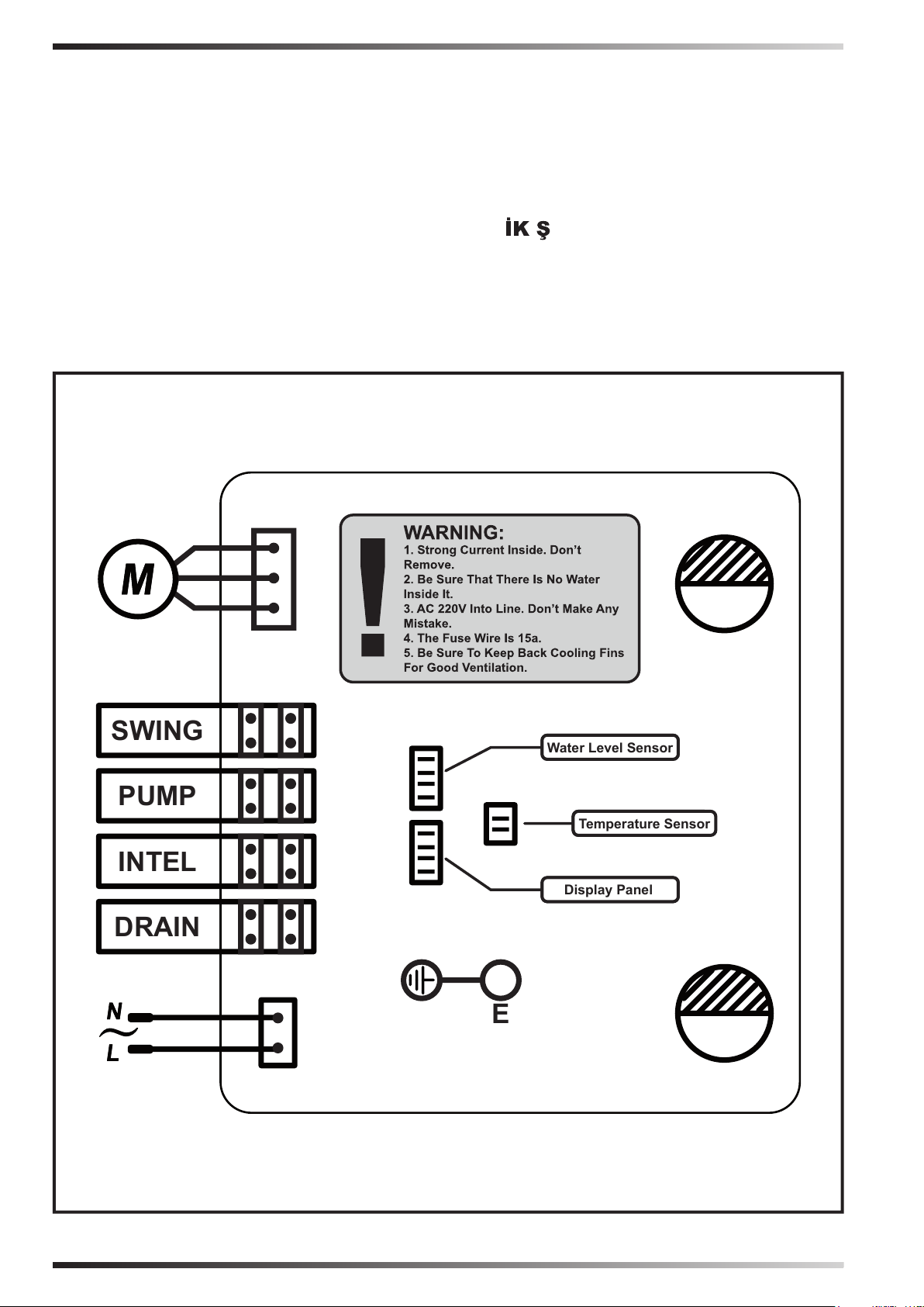
SWING
PUMP
INTEL
DRAIN
Water level sensor
Water Level Sensor
Water level sensorDisplay Panel
Water level sensorTemperature Sensor
E
WIRING DIAGRAMS - SCHEMI ELETTRICI - SCHALTPLÄNE - ES-
QUEMAS ELÉCTRICOS - SCHEMAS ELECTRIQUES - ELEKTRISCHE
SCHEMA’S - ESQUEMAS ELÉCTRICOS - ELEKTRISKE SKEMAER
- SÄHKÖKAAVIOT - KOPLINGSSKJEMA - ELEKTRISKA KOP-
PLINGSSCHEMAN - SCHEMATY ELEKTRYCZNE - ЭЛЕКТРИЧЕСКИЕ
СХЕМЫ - ELEKTRICKÁ SCHÉMATA - VILLANYBEKÖTÉSI RAJ-
ZOK - ELEKTRIČNE SHEME - ELEKTR EMALARI - ELEKTRIČNE
SHEME - ELEKTROS SCHEMOS - ELEKTRISKĀS SHĒMAS - ELE-
KTRISKEEMID - SCHEME ELECTRICE - ELEKTRICKÉ SCHÉMY -
ЕЛЕКТРИЧЕСКИ СХЕМИ - ЕЛЕКТРИЧНІ СХЕМИ - ELEKTRIČNE
ŠEME - ΗΛΕΚΤΡΙΚΑ ΣΧΕΔΙΑ - 线路图 - ЭЛЕКТРЛІ СҮЛБЕЛЕР
Figures and texts of this book are protected by COPYRIGHT.
Page 69
CE CONFORMITY CERTIFICATE - DICHIARAZIONE DI CONFORMITÀ CE - EG-KON-
FORMITÄTSERKLÄRUNG - DECLARACIÓN DE CONFORMIDAD CE - DECLARATION DE
CONFORMITE CE - EG-CONFORMITEITVERKLARING - DECLARAÇÃO DE CONFORMIDA-
DE CE - EU-OVERENSSTEMMELSESERKLÆRING - EY-VAATIMUSTENMUKAISUUSVA-
KUUTUS - CE-SAMSVARSERKLÆRING - EG-FÖRSÄKRAN OM ÖVERENSSTÄMMELSE
- DEKLARACJA ZGODNOŚCI WE - ДЕКЛАРАЦИЯ О СООТВЕТСТВИИ СЕ - PROHLÁŠENÍ
O SHODĚ CE - EK MEGFELELŐSÉGI NYILATKOZAT - IZJAVA O SKLADNOSTI IN
OZNAKA CE - CE UYGUNLUK BEYANI - IZJAVA CE O SUKLADNOSTI - ES ATITIKTIES
DEKLARACIJA - EK ATBILSTĪBAS - DEKLARĀCIJA - EÜ VASTAVUSDEKLARATSIOON -
DECLARAŢIE DE CONFORMITATE CE - PREHLÁSENIE O ZHODE CE - ДЕКЛАРАЦИЯ ЗА
СЪВМЕСТИМОСТ СЕ - ДЕКЛАРАЦІЯ ВІДПОВІДНОСТІ CE - IZJAVA CE O PRIKLADNOSTI
ΔΗΛΩΣΗ ΣΥΜΜΟΡΦΩΣΗΣ CE - CE 符合性声明
MCS ITALY S.p.A. Via Gardesana 11, -37010- Pastrengo (VR), ITALY
Product: - Prodotto: - Produkt: - Producto: - Produit: - Product: - Produto: - Produkt: - Tuote: - Produkt: - Produkt:
- Produkt: - Изделие: - Výrobek: - Termék: - Izdelek: - Ürün: - Proizvod: - Gaminys: - Ierīce: - Toode: - Produsul: -
Výrobok: - Продукт: - Виріб: - Proizvod: - Προϊόν: - 产品:
BCF 230RB - BCF 230AB
BCF 230AL - BCF 230AU
We declare that it is compliant with: - Si dichiara che è conforme a: - Es wird als konform mit den folgenden
Normen erklärt: - Se declara que está en conformidad con: - Nous déclarons sa conformité à: - Hierbij wordt
verklaard dat het product conform is met: - Declara-se que está em conformidade com: - Vi erklærer at produktet
er i overensstemmelse med: - Vakuutetaan olevan yhdenmukainen: - Man erklærer at apparatet er i overens-
stemmelse med: - Härmed intygas det att produkten är förenlig med följande: - Oświadcza się, że jest zgodny z: -
Заявляем о соответствии требованиям: - Prohlašuje se, že je v souladu s: - Kijelentjük, hogy a termék megfelel
az alábbiaknak: - Izpolnjuje zahteve: - Aşağıdaki standartlara uygun olduğunu beyan ederiz: - Izjavljuje se da je u
skladu s: - Pareiškiame, kad atitinka: - Tiek deklarēts, ka atbilst: - Käesolevaga deklareeritakse, et toode vastab:
- Declarăm că este conform următoarelor: - Prehlasuje sa, že je v súlade s: - Декларира се че отговаря на: Відповідає вимогам: - Izjavljuje se da je u skladu s: - Δηλώνουμε ότι είναι σύμφωνο με: - 兹证明符合:
2014/30/EU, 2014/35/EU, 2011/65/EU, 2006/42/EC
EN 55014-1, EN 55014-2, EN 61000-3-2, EN 61000-3-3,
EN 60335-1, EN 60335-2-80, EN 60335-2-98
Pastrengo, 16/01/2016
Figures and texts of this book are protected by COPYRIGHT.
Stefano Verani (CEO MCS Group)
Page 70

►en - DISPOSAL OF THE PRODUCT
-This product has been designed and manufactured with top-quality materials and components, which can be re-cycled and reused.
-When a crossed-wheely bin symbol is attached to the product, it means that the product is protected by the, 2002/96/EC European
Directive.
-Please obtain information regarding the local dierentiated collection system for electrical and electronic products.
-Respect local Standards in force and do not dispose of old products as normal domestic waste. Correct disposal of the product
helps to prevent possible negative consequences for health, the environment and mankind.
►it - SMALTIMENTO DEL PRODOTTO
-Questo prodotto è stato progettato e fabbricato con materiali e componenti di alta qualità, che possono essere riciclati e riutilizzati.
-Quando ad un prodotto è attaccato il simbolo del bidone con le ruote segnato da una croce, signica che il prodotto è tutelato
dalla Direttiva Europea 2002/96/CE.
-Si prega di informarsi in merito al sistema locale di raccolta dierenziata per i prodotti elettrici ed elettronici.
-Rispettare le norme locali in vigore e non smaltire i prodotti vecchi nei normali riuti domestici. Il corretto smaltimento del prodotto
aiuta ad evitare possibili conseguenze negative per la salute dell’ambiente e dell’uomo.
►de - ENTSORGUNG DES PRODUKTS
-Dieses Produkt wurde unter Verwendung von Qualitätsmaterialien und -bauteilen entwickelt und hergestellt, die recycelt und
wieder verwendet werden können.
-Ist ein Produkt gekennzeichnet durch die Mülltonne mit Rädern und einem Kreuz, wird hier angezeigt, dass dieses Produkt durch
die europäische Direktive 2002/96/EG überwacht ist.
-Es wird gebeten, sich über die vor Ort bestehende Mülltrennung bezüglich elektrischer und elektronischer Produkte zu informieren.
-Die vor Ort geltenden Vorschriften zur Müllentsorgung müssen eingehalten werden und alte Produkte dürfen nicht zusammen mit
dem Hausmüll entsorgt werden. Die ordnungsgemäße Entsorgung des Produkts hilft mögliche negative Folgen für Gesundheit
und Umwelt zu vermeiden.
►es - ELIMINACIÓN DEL PRODUCTO
-Este producto ha sido diseñado y fabricado con materiales y componentes de alta calidad que se pueden reciclar y reutilizar.
-Cuando en el producto se encuentra el símbolo del contenedor con las ruedas tachado con una cruz, signica que el producto
está tutelado por la Directiva europea 2002/96/CE.
-Se ruega informarse acerca del sistema local de recogida selectiva para los productos eléctricos y electrónicos.
-Respete las normas locales vigentes y no elimine los productos viejos junto con los residuos domésticos normales. La eliminación
correcta del producto ayuda a evitar posibles consecuencias negativas para la salud del ambiente y del hombre.
►fr - SE DÉBARRASSER DE VOTRE PRODUIT USAGÉ
-Ce produit a été conçu et fabriqué avec des matériaux et des composants de haute qualité, qui peuvent être recyclés et utilisés
de nouveau.
Lorsque le symbole d’une poubelle à roue barrée est appliqué à un produit, cela signie que le produit est couvert par la Directive
Européenne 2002/96/CE.
Veuillez vous informer du système local de séparation des déchets électriques et électroniques.
Veuillez agir selon les règles locale set ne pas jeter vos produits usagés avec les déchets domestiques usuels. Jeter correctement
votre produit usagé aidera à prévenir les conséquences négatives potentielles contre l’environnement et la santé humaine.
►nl - VERWIJDERING VAN HET PRODUCT
-Dit product werd ontworpen en gemaakt met hoogwaardige materialen en componenten, die gerecycleerd en herbruikt kunnen
worden.
-Wanneer op een product het symbool van de afvalbak op wielen met een kruis erdoor is aangebracht, betekent dit dat het product
valt onder de Europese Richtlijn 2002/96/EG.
-Gelieve inlichtingen in te winnen betreende het plaatselijke systeem voor gedierentieerde inzameling van elektrische en
elektronische toestellen.
-Respecteer de plaatselijke normen die van kracht zijn, en verwijder de oude toestellen niet als gewoon huishoudelijk afval.
Een correcte verwijdering van het product helpt om mogelijke negatieve gevolgen voor de gezondheid van mens en milieu te
voorkomen.
►pt - ELIMINAÇÃO DO PRODUTO
-Este produto foi projetado e fabricado com materiais e componentes de alta qualidade que podem ser reciclados e reutilizados.
-Quando for axado em um produto o símbolo do bidão com rodas marcado com uma cruz, signica que o produto é protegido
pela Diretiva Europeia 2002/96/CE.
-Solicitamos informar-se sobre o sistema local de recolha diferenciada para os produtos elétricos e eletrónicos.
-Respeitar as normas locais em vigor e não eliminar os produtos antigos como normais detritos domésticos. A correta eliminação
do produto ajuda a evitar possíveis consequências negativas para a saúde do ambiente e do homem.
Figures and texts of this book are protected by COPYRIGHT.
Page 71

►da - BORTSKAFFELSE
-Dette produkt er designet og fremstillet med materialer og dele af høj kvalitet, der kan genanvendes.
-Når et produkt er mærket med symbolet, der viser en aaldsspand på hjul med et kryds over, betyder det, at produktet er beskyttet
af EF-Direktiv 2002/96/EF.
-Der henstilles til, at man informerer sig angående det lokale aaldssorteringssystem for elektriske og elektroniske produkter.
-De gældende lokale regler skal overholdes, og de gamle produkter må ikke bortskaes sammen med husholdningsaaldet. Ved
at bortskae dette produkt korrekt, medvirker De til at forhindre eventuelle negative påvirkninger af miljøet og folkesundheden.
► - TUOTTEEN HÄVITTÄMINEN
-Tämä tuote on suunniteltu ja valmistettu korkealaatuisia materiaaleja ja osia käyttämällä, jotka voidaan kierrättää ja käyttää
uudelleen.
-Kun tuotteeseen on kiinnitetty viivattu roskasäiliön merkki, se tarkoittaa, että tuotetta suojaa Euroopan yhteisön direktiivi 2002/96/
EY.
-Hanki tietoja paikallisesta sähkö- ja elektroniikkaromujen erilliskeräyksestä.
-Noudata voimassa oleva määräyksiä äläkä hävitä vanhoja tuotteita kotitalousjätteiden mukana. Tuotteen oikea hävittäminen
auttaa suojelemaan luontoa ja välttää väärän romutuksen aiheuttamien terveysriskien syntymistä.
►no - AVFALLSHÅNDTERING
-Dette produktet er utformet og produsert med materialer og deler av høy kvalitet, og som kan gjenvinnes.
-Når det på et produkt nnes et symbol som forestiller en avfallsbeholder med et kryss over, betyr dette at produktet er underlagt
EU-direktiv 2002/96/CE.
-Vennligst informer dere angående de lokale reglene som gjelder kassering av elektrisk og elektronisk avfall.
-Ta hensyn til gjeldende regelverk og ikke kast gamle produkter sammen med husholdningsavfall. Riktig avfallshåndtering av
produktet bidrar til å unngå potensielle negative konsekvenser for miljøet og menneskenes helse.
►sv - PRODUKTENS BORTSKAFFANDE
-Den här produkten har projekterats och tillverkats med material och komponenter av hög kvalitet som kan återvinnas och
återanvändas.
-När ett klistermärke med en symbol med överkorsad soptunna med hjul sitter på produkten, betyder detta att produkten är
skyddad av Eu-direktiv 2002/96/EG.
-Vi ber er inhämta upplysningar vid er lokala återvinningsstation för elektriska och elektroniska produkter.
-Följ lokala gällande bestämmelser och skaa inte bort förbrukade produkter i det vanliga hushållsavfallet. Ett korrekt bortskaande
av produkten hjälper till att undvika möjliga negativa eekter på miljö- och männsikohälsa.
►pl - UTYLIZACJA PRODUKTU
-Niniejszy produkt został wyprodukowany z najwyższej jakości materiałów, które mogą być poddane recyklingowi i zostać ponownie
użyte.
-Symbol przekreślonego kosza na śmieci umieszczony na produktu oznacza, że ów produkt jest chroniony Dyrektywą Unii
Europejskiej 2002/96/WE.
-Należy zapoznać się z lokalnym systemem zbiórki produktów elektronicznych i elektrycznych.
-Stare produkty muszą być usuwane zgdonie z obowiązującymi normami. Odpowiednia utylizacja urządzeń elektrycznych i
elektronicznych zapobiega następstwom negatywnie wpływającym na zdrowie, środowisko i całą ludzkość.
►ru - УТИЛИЗАЦИЯ ПРОДУКТА
-Данный продукт был произведен из наивысшего качества материалов, которые могут быть подданы рециклингу и
повторно использованы.
-Символ зачеркнутой мусорной корзины, размещенный на продукте, обозначает, что этот продукт защищен Директивой
Европейского Союза 2002/96/CE.
-Следует ознакомиться с локальной системой сбора электронных и электрических продуктов.
-Старые продукты должны быть утилизированы в соответствии с действующими нормами. Соответствующая утилизация
электрических и электронных приборов предотвращает последствия, негативно влияющие на здоровье, окружающую
среду и все человечество.
►cs - LIKVIDACE VÝROBKU
-Tento výrobek byl navržen a vyroben z vysoce kvalitních materiálů a komponentů, které lze recyklovat a znovu použít.
-Je-li na výrobku symbol přeškrtnutého kontejneru, znamená to, že na výrobek se vztahuje Evropská Směrnice 2002/96/ES.
-Informujte se o místním systému pro oddělený sběr elektrických a elektronických výrobků.
-Dodržujte místní předpisy a nelikvidujte staré produkty spolu s běžným komunálním odpadem. Správná likvidace výrobku pomůže
předcházet možným negativním dopadům na životní prostředí a lidské zdraví.
Figures and texts of this book are protected by COPYRIGHT.
Page 72
►hu - HULLADÉKBA HELYEZÉS
-A termék kiváló minőségű újrahasznosítható és újból felhasználható alkotóelemek felhasználásával készült.
-Ha terméken elhelyezésre került az áthúzott hulladékgyűjtőt ábrázoló jel, az azt jelenti, hogy a termékre a 2002/96/EK irányelv
vonatkozik.
-Kérjük, tájékozódjon az elektromos és elektronikus hulladékok szelektív gyűjtéséről.
-Tartsa be a helyben hatályos előírásokat, és ne a terméket ne helyezze a háztartási hulladékgyűjőbe. A megfelelő hulladékgyűjtéssel
elkerülhető, hogy a hulladékok károsítsák a környezetet ill. az emberi egészséget.
►sl - ODLAGANJE IZDELKA
-Ta izdelek je bil zasnovan in izdelan iz materialov in komponent visoke kakovosti, ki jih je mogoče reciklirati in ponovno uporabiti.
-Ko je izdelek označen z znamenjem prekrižanega smetnjaka na kolesih, pomeni, da zanj veljajo določbe evropske Direktive
2002/96/ES.
-Pozanimajte se o načinu ločenega zbiranja električne in elektronske opreme, ki velja v vašem kraju.
-Upoštevajte veljavne predpise in odsluženih izdelkov ne odlagajte med gospodinjske odpadke. Pravilno odlaganje izdelka prispeva
k izogibanju morebitnim negativnim posledicam za zdravje okolja in ljudi.
►tr - ÜRÜNÜN İMHA EDİLMESİ
-Bu ürün, geri dönüştürülüp tekrar kullanılabilen, yüksek kaliteli malzeme ve bileşenler kullanılarak tasarlanıp üretilmiştir.
-Herhangi bir üründe, üzerinde çarpı işareti bulunan tekerlekli bidon bulunuyorsa bu, ürünün 2002/96/CE Avrupa Direkti tarafından
korunduğunu belirtir.
-Lütfen bulunduğunuz bölgedeki elektrikli ve elektronik aletler için olan çöp ayrıştırma sistemi ile ilgili bilgi edininiz.
-Konuyla ilgili yerel düzenlemelere uyunuz ve eski ürünleri normal evsel atıklarla beraber atmayınız. Ürünün doğru şekilde imha
edilmesi, çevre ve insan sağlığını tehdit edici olumsuz sonuçların önlenmesine yardımcı olur.
►hr - ODBACIVANJE PROIZVODA
-Ovaj je proizvod osmišljen i izrađen s visokokvalitetnim materijalima i komponentama koje se mogu reciklirati i ponovno iskoristiti.
-Kada se na proizvod stavi simbol prekrižene kante na kotačima, to znači da je on podvrgnut Europskoj Smjernici 2002/96/CE.
-Informirajte se u svezi s lokalnim načinom diferencijalnog sakupljanja električnih i elektronskih proizvoda.
-Poštujte lokalne propise na snazi i ne odbacujte stare proizvode zajedno sa običnim kućnim otpadom. Pravilnim odbacivanjem
proizvoda spriječit ćete moguće negativne posljedice za okoliš i za zdravlje ljudi.
►lt - GAMINIO SUNAIKINIMAS
-Šis gaminys buvo sukurtas ir pagamintas iš aukštos kokybės medžiagų bei dalių, kurios gali būti perdirbtos arba panaudotos dar
kartą.
-Kai gaminys yra pažymėtas perbraukto atliekų konteinerio su ratukais ženklu, tai reiškia, kad gaminys yra saugomas pagal ES
direktyvą 2002/96/EB.
-Prašome pasidomėti apie vietinę elektros ir elektronikos atliekų rūšiavimo sistemą.
-Laikykitės vietinių galiojančių taisyklių ir nemeskite senų gaminių su įprastomis buitinėmis atliekomis. Tinkamai sunaikinę gaminį
išvengsite galimų neigiamų pasekmių aplinkai ir žmonių sveikatai.
►lv - PRODUKTA IZNĪCINĀŠANA
-Šis produkts tika izveidots un ražots ar augstas kvalitātes materiāliem un sastāvdaļām, kas var būt savāktas un atkārtoti izmantotas.
-Kad pie produkta ir piestiprināts atkritumu tvertnes simbols ar riteņiem, kas ir pārsvītrots ar krustu, tas nozīmē, ka produktu aizstāv
Eiropas Direktīva 2002/96/EK.
-Lūdzam Jūs gūt informāciju par vietēju centru, kas savāc elektriskās un elektroniskā ierīces.
-Ievērot vietējās pastāvošās normas un neiznīcināt vecus produktus, kā parastus mājas atkritumus. Produkta pareizā iznīcināšana
palīdz izvairīties no iespējamām negatīvām sekām vides un cilvēku veselībai.
►et - TOOTE KASUTUSEST KÕRVALDAMINE
-See toode on projekteeritud ja toodetud kvaliteetsetest materjalidest ja osadest, mida võib uuesti ringlusse võtta ja korduskasutada.
-Kui tootel on märk, millel on ratastega prügikast, millele on rist peale tõmmatud, tähendab see, et toodet kaitseb Euroopa direktiiv
2002/96/EÜ.
-Palun tutvuge kohaliku elektri- ja elektroonikatoodete lahuskogumise süsteemiga.
-Täitke kehtivaid kohalikke õigusnorme ning ärge visake vana toodet olmejäätmete hulka. Toote õige kõrvaldamine aitab vältida
võimalikke negatiivseid tagajärgi keskkonna ja inimeste tervisele.
Figures and texts of this book are protected by COPYRIGHT.
Page 73
►ro - SCOATEREA DEFINITIVĂ DIN UZ A PRODUSULUI
-Acest produs a fost proiectat şi fabricat cu materiale şi componente de înaltă calitate care pot reciclate şi refolosite.
-Când pe produs este aplicat simbolul unei pubele cu roţi, marcată cu o cruce, înseamnă că produsul respectiv este conform
Directivei Europene 2002/96/CE.
-Vă rugăm să vă informaţi în ceea ce priveşte colectarea separată a produselor electrice şi electronice.
-Respectaţi normele locale în vigoare şi nu depozitaţi produsele vechi împreună cu deşeurile menajere. Eliminarea corectă a
produsului ajută la eliminarea consecinţelor negative pe care acesta le poate avea asupra mediului înconjurător şi a persoanelor.
►sk - LIKVIDÁCIA VÝROBKU
-Tento výrobok bol navrhnutý a vyrobený z vysoko kvalitných materiálov a komponentov, ktoré je možné recyklovať a znovu použiť.
-Ak je na výrobku symbol prečiarknutého kontajnera, znamená to, že na výrobok sa vzťahuje Európska Smernica 2002/96/ES.
-Informujte sa o miestnom systéme pre oddelený zber elektrických a elektronických výrobkov.
-Dodržujte miestne predpisy a nelikvidujte staré produkty spolu s bežným komunálnym odpadom. Správna likvidácia výrobku
pomôže predchádzať možným negatívnym dopadom na životné prostredie a ľudské zdravie.
►bg - ИЗХВЪРЛЯНЕ НА УРЕДА
-Това изделие е проектирано и произведено с материали и компоненти от високо качество, които могат да се рециклират
или използват повторно.
-Когато на някое изделие е поставен символ с бидон на колелца, маркиран с хикс, това означава, че изделието е защитено
съгласно Европейска Директива 2002/96/EO.
-Моля да се информирате относно местанат система за разделно изхвърляне на електрически и електронни изделия.
-Спазвайтдействащите местни нормативи и не изхвърляйте изделията, заедно с нормалните домакински отпадъци.
Правилното изхвърляне на изделията, помага за избягване на възможни отрицателно последици, за здравето на хората
и за опазване на околната среда.
►uk - УТИЛІЗАЦІЯ ВИРОБУ
-Цей виріб був спроектований і вироблений з використанням високоякісних матеріалів і комплектуючих, які можуть бути
повторно перероблені і використані.
-Якщо на виріб нанесено символ перекресленого бака з колесами для сміття, це означає, що виріб відповідає Директиві
Європейського Союзу 2002/96/CE.
-Просимо ознайомитися з інформацією щодо місцевої системи роздільного збору сміття для електричного і електронного
обладнання.
-Дотримуйтесь чинних місцевих правил і не викидайте старі вироби до звичайних побутових відходів. Правильна
утилізація виробу допомагає уникнути можливих негативних наслідків для довкілля і здоров’я людей.
►bs - ODLAGANJE PROIZVODA
-Ovaj je proizvod dizajniran i proizveden korištenjem materijala i komponenata visoke kvalitete koji se mogu reciklirati i ponovo
koristiti.
-Kada se na ovaj proizvod postavi simbol prekrižene kante /obilježene krstom na točkovima, to znači da je proizvod podložan
Evropskoj Direktivi 2002/96/CE.
-Molimo Vas da se informirate o lokalnom sistemu diferencijalnog sakupljanja električnih i elektronskih proizvoda.
-Poštujte lokalne propise na snazi i ne odbacujte stare proizvode u obični kućanski otpad. Pravilno odlaganje proizvoda pomaže i
onemogućuje negativne posljedice za zdravlje ljudi i okoliša
►el - ΔΙΆΘΕΣΗ ΤΟΥ ΠΡΟΪΌΝΤΟΣ
-Το προϊόν αυτό σχεδιάστηκε και κατασκευάστηκε με υλικά και εξαρτήματα υψηλής ποιότητας, τα οποία μπορούν να ανακυκλωθούν
και να ξαναχρησιμοποιηθούν.
-Όταν ένα προϊόν είναι συνδεδεμένο με το σύμβολο του διαγεγραμμένου τροχοφόρου σημειωμένο με ένα σταυρό, σημαίνει ότι το
προϊόν καλύπτεται από την Ευρωπαϊκή Οδηγία 2002/96/EΚ.
-Σας συνιστούμε να ενημερωθείτε σχετικά με το τοπικό σύστημα συλλογής για την ανακύκλωση ηλεκτρικών και ηλεκτρονικών
προϊόντων.
-Τηρήστε τους τοπικούς κανονισμούς που ισχύουν και μην απορρίπτετε τα παλαιά προϊόντα στα οικιακά απορρίμματα. Η σωστή
διάθεση του προϊόντος βοηθά στην αποφυγή πιθανών αρνητικών συνεπειών για την υγεία του περιβάλλοντος και του ανθρώπου.
►zh - 弃置旧的产品
-该产品是由高质量的原材料和零配件生产而成的 ,可以进行回收再利用
-当这个标识标签出现在产品上时,它表明这个产品符合 European Directive 2002/96/EC标准.
-请熟知产品实际使用地关于处理废弃的电子元器件的相关法律规定.
-请严格根据当地法规处理废弃的产品和包装,并确保不和生活垃圾混装. 正确的处理方式可以避免对环境和人体健康产生的潜在威
胁.
Figures and texts of this book are protected by COPYRIGHT.
Page 74

MCS Italy S.p.A.
Via Gardesana 11, -37010-
Pastrengo (VR), Italy
info@mcsitaly.it
MCS Italy S.p.A.
Виа Гардесана 11, 37010
Пастренго (Верона), Италия
info@mcsitaly.it
MCS Central Europe Sp. z o.o.
ul. Magazynowa 5A,
62-023 Gądki, Poland
oce@mcs-ce.pl
MCS Russia LLC
ul. Transportnaya - 22 ownership 2,
142802, STUPINO, Moscow region, Russia
info@mcsrussia.ru
MCS China LTD
Unit 2B, 512 Yunchuan Rd.,
Shanghai,
201906, China
oce@mcs-china.cn
EURITECSA
C/Calabozos, 6 Polígono Industrial,
28108 Alcobendas (Madrid)
Spain
euritecsa@euritecsa.es
MCS Central Europe Sp. z o.o.
ул. Магазинова, 5A,
62-023 Гадки, Польша
oce@mcs-ce.pl
ООО «ЭмСиЭс Россия»
Ул. Транспортная, владение 22/2,
142802, г.Ступино, Московская обл., РФ
info@mcsrussia.ru
MCS China LTD
Юньчуань роад, 512,
строение 2В, Шанхай,
201906, Китай
oce@mcs-china.cn
EURITECSA
Ц/Калабозос, 6 Полигоно Индустриал,
28108 Алкобендас (Мадрит)
Испания
euritecsa@euritecsa.es
Figures and texts of this book are protected by COPYRIGHT.
Cod. 4140.383 Edition 16 - Rev. 3
 Loading...