

Page 1

GB - PORTABLE FORCED AIR HEATERS
FR - APPAREILS DE CHAUFFAGE INDIVIDUELS À AIR FORCÉ
DE - TRAGBARE HOCHDRUCK EISSLUFTTURBINEN
NL - VERPLAATSBARE HETELUCHTKANONNEN
IT - GENERATORE D’ARIA CALDA A RISCALDAMENTO DIRETTO
ES - CALENTADORES PORTATILES DE AIRE FORZADO
SV - PORTABEL VÄRMEFLÄKT MED FORCERAT LUFTFLÖDE
FI - KANNETTAVA KUUMAILMAPUHALLIN
DK - VARMEKANONER
NO - TRANSPORTABLE VARMEAPPARATER MED VIFTE
PL - PRZENOŚNE OLEJOWE NAGRZEWNICE POWIETRZA
RU - ПEPEДBИЖHЫE BOЗДYXOHAГPEBATEЛИ
C CИCTEMOЙ HAДДYBA
HU - HORDOZHATÓ, GÉPI LÉGFŰTŐ BERENDEZÉS
CZ - PŘENOSNÉ OHŘÍVAČE S NUCENÝM OBĚHEM VZDUCHU
OWNER’S MANUAL - MANUEL D’ITILISATION - BEDIENUNGSANLEITUNG
- GEBRUIKERSHANDLEIDING - MANUALE D’ISTRUZIONE - MANUALE DEL
PROPIETARIO - ANVÄNDARMANUAL - KÄYTTÖOPAS - BRUGSANVISNING
- BRUKERHÅNDBOK - INSTRUKCJA OBSŁUGI - PYKOBOДCTBO ДЛЯ
ПOЛЬЗOBATEЛЯ - FELHASZNÁLÓI KÉZIKÖNYV - PŘÍRUČKA PRO UŽIVATELE
Heater sizes - Production de la chaleur - Heizgerät-Größen - Vermogen - Potenza termica -
Tamaños - Effekt storlekar - Lämmittimen lämpötehot - Størrelse - Størrelser - Nagrzewnice o
wydajności - Moшhocть haгpeвaтeлeй - Fűtőberendezések teljesítménye - Vákon ohřívačů:
10, 18,5, 20, 29 y 44 kW
(35.000, 64.000, 70.000, 100.000 and 150.000 Btu/Hr)
Models - Modèles - Modelle - Modellen - Modelli - Modelos - Modeller
- Mallit - Model - Modeller - Modele - Moдeли - Modellek - Modely:
B 35 CEL, B 65 CEL, B 70 CEL, B 100 CEL, B 150 CEL
4111.492
Edition 09 - Rev.03
Page 2

SPECIFICATIONS - SPÉCIFICATIONS - TECHNISCHE DATEN -
TECHNISCHE GEGEVENS - DATI TECNICI - ASPECIFICACIONES
- SPECIFIKATIONER - TEKNISET TIEDOT - SPECIFIKATIONER
- SPESIFIKASJONER - SPECYFIKACJE - TEXHИЧECKИE
XAPAKTEPИCTИKИ - MŰSZAKI ADATOK - TECHNICKÉ ÚDAJE
MODEL B 35 CEL B 65 CEL B 70 CEL B 100 CEL B 150 CEL
10 kW
35.000 Btu/h
18,5 kW
64.000 Btu/h
20 kW
70.000 Btu/h
29 kW
100.000 Btu/h
44 kW
150.000 Btu/h
MAX
280 m³/h 400 m³/h 400 m³/h 800 m³/h 900 m³/h
0,86 Kg/h 1,55 Kg/h 1,7 Kg/h 2,45 Kg/h 3,72 Kg/h
DIESEL
KEROSENE
15 Lt 19 Lt 19 Lt 44 Lt 44 Lt
220-240 V / 50 Hz
0,02 kW - 0,8 A
DIESEL
KEROSENE
220-240 V / 50 Hz
0,09 kW - 1 A
DIESEL
KEROSENE
220-240 V / 50 Hz
0,09 kW - 1 A
DIESEL
KEROSENE
220-240 V / 50 Hz
0,19 kW - 1,2 A
DIESEL
KEROSENE
220-240 V / 50 Hz
0,19 kW - 1,2 A
RPM
1425 2850 2850 2850 2850
.
Page 3
PORTABLE FORCED AIR HEATER
OWNER’S MANUAL
GB
Heater Sizes: 10, 18,5, 20, 29, 44 kW
Models: 35.000, 64.000, 70.000, 100.000, 150.000 Btu/Hr
IMPORTANT: Read and understand this manual before assembling, starting or servicing heater.
Improper use of heater can cause serious injury.Keep this manual for future reference.
SAFETY INFORMATION 2
PRODUCT IDENTIFICATION 3
UNPACKING 3
FUELS 3
ASSEMBLY 3
VENTILATION 4
THEORY OF OPERATION 4
OPERATION 4
STORING, TRANSPORTING OR SHIPPING 4
PREVENTATIVE MAINTENANCE SCHEDULE 5
TROUBLESHOOTING 5
SERVICE PROCEDURES 6
ACCESSORIES 12
WARRANTY INFORMATION 12
Page 4

2
GB
SAFETY INFORMATION
SAFETY INFORMATION
!
WARNINGS
IMPORTANT: Read this owner’s manual carefully and
completely before trying to assemble, operate, or service
this heater. Improper use of this heater can cause serious
injury or death from burns, re, explosion, electrical
shock, and carbon monoxide poisoning.
!
DANGER: Carbon monoxide poisoning may lead to
death!
Carbon Monoxide Poisoning: Early sign sof carbon monoxide
poisoning resemble the u, with headaches, dizziness, and/or
nausea. If you have these signs, the heater may not be working
properly. Get fresh air at once! Have heater serviced. Some
people are more affected by carbon monoxide than others.
These include pregnant women, persons with heart or lung disease or anemia,those under the in uence of alcohol, and those
at high altitudes.
Make certain you read and understand all warnings. Keep this
manual for reference. It is your guide to safe and proper operation of this heater.
● Use only kerosene or No. 1 fuel oil to avoid risk of re or ex-
plosion. Never use gasoline, naphtha, paint thinners, alcohol,
or other highly ammable fuels.
● Fueling
a) Personnel involved with fueling shall be quali ed and
thoroughly familiar with the manufacturer’s instructions and
applicable regulations regarding the safe fueling of heating
units.
b) Only the type of fuel speci ed on the heater’s data plate
shall be used.
c) All ame, including the pilot light, if any, shall be extinguis-
hed and the heater allowed to cool, prior to fueling.
d) During fueling, all fuel lines and fuelline connections shall
be inspected for leaks. Any leaks shall be repaired prior to
returning the heater to service.
e) At no time shall more than one day’s supply of heater fuel
be stored inside a building in the vicinity of the heater. Bulk
fuel storage shall be outside the structure.
f) All fuel storage shall be located a minimum of 762cm (25
feet) from heaters, torches, welding equipment, and similar
sources of ignition (exception: the fuel reservoir integral with
the heater unit).
g) Whenever possible, fuel storage shall be con ned to areas
where oor penetrations do not permit fuel to drip onto or be
ignited by a re at lower elevation.
h) Fuel storage shall be in accordance with the authority having jurisdiction.
● Never use heater where gasoline, paint thinner, or other highly
ammable vapors are present.
● Follow all local ordinances and codes when using heater.
● Heaters used in the vicinity of tarpaulins, canvas, or similar
enclosure materials shall be located a safe distance from
such materials. The recommended minimum safe distance is
304.8cm (10 feet). It is further recommended that these enclosure materials be of a re retardant nature. These enclosure
materials shall be securely fastened to prevent them from
igniting or from upsetting the heater due to wind action.
● Use only in well-vented areas. Before using heater, provide at
least a 2800 square cm (three-square-foot) opening of fresh,
outside air for each 29 kw (100,000 Btu/Hr) of rating.
● Use only in places free of ammable vapors or high dust
content.
● Use only the electrical voltage and frequency speci ed on
model plate.
● Use only a three-prong, grounded extension cord.
● Minimum heater clearances from combustibles:Outlet: 250 cm
(8 Ft.)Sides, Top, and Rear: 125 cm (4 Ft.)
● Locate heater on a stable and level surface if heater is hot or
running or a re may occur.
● When moving or storing heater, keep heater in a level position
or fuel spillage may occur.
● Keep children and animals away from heater.
● Unplug heater when not in use.
● When used with thermostat, heater may start anytime.
● Never use heater in living or sleeping areas.
● Never block air inlet (rear) or air outlet (front) of heater.
● Never move, handle, refuel, or service a hot, operating, or
plugged-in heater.
● Never attach duct work to front or rear of heater.
Page 5
PRODUCT IDENTIFICATION
UNPACKING
FUELS
ASSEMBLY
3
GB
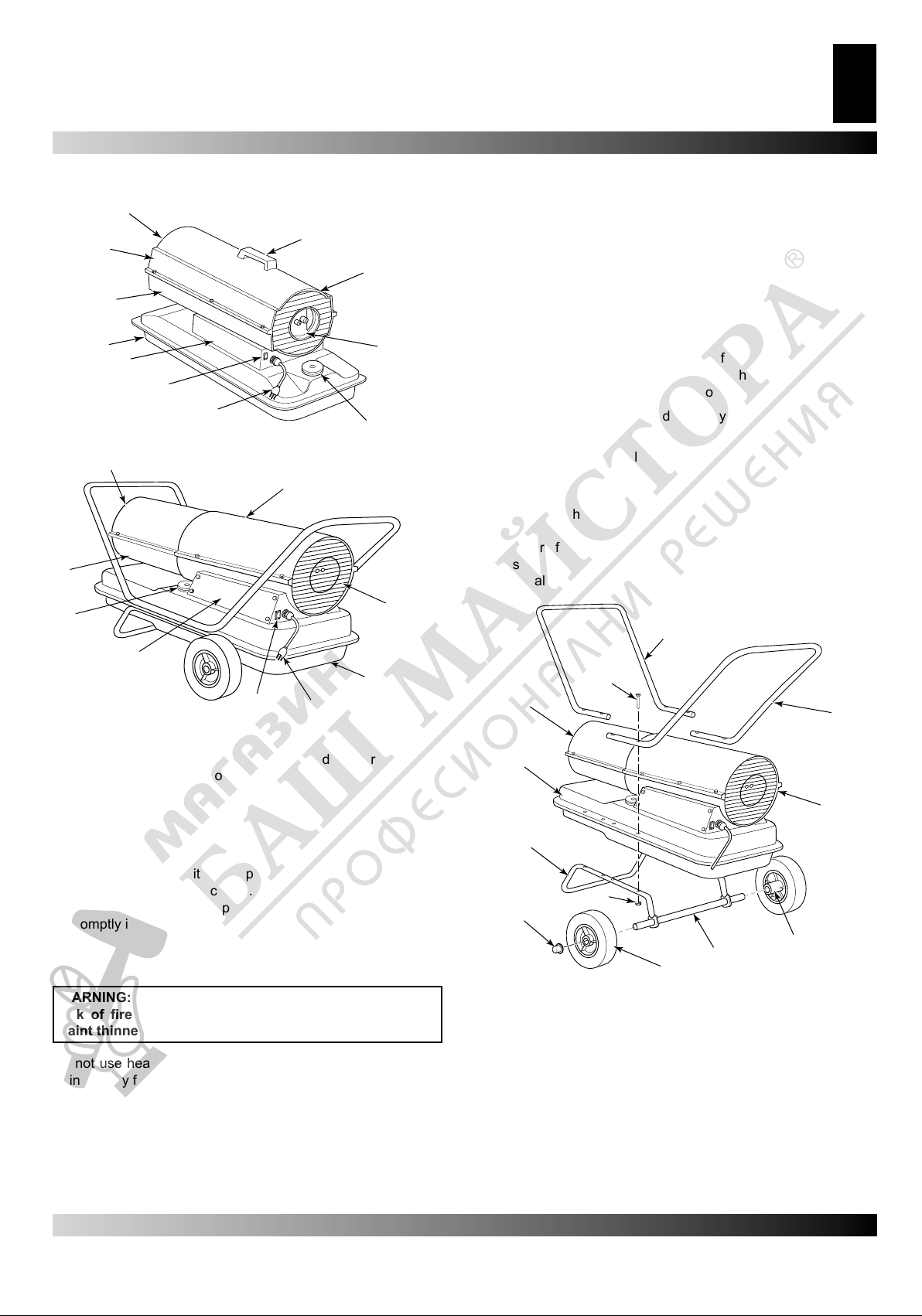
PRODUCT IDENTIFICATION
A.
B.
M.
C.
L.
I.
H.
G.
F.
Figure 1 – Model 35.000, 64.000 e 70.000 Btu/Hr
A.
M.
L.
E.
H.
G.
Figure 2 – Model 100.000 e 150.000 Btu/Hr
(see gure 1, e 2)
A. Hot Air Outlet, B. Handle, C. Fan Guard, D. Air Filter End
Cover, E. Fuel Cap, F. Power Cord, G. ON/OFF Switch with
Light, H. Side Cover, I. Fuel Tank, L. Lower Shell, M. Upper
Shell.
F.
D.
E.
C.
I.
ASSEMBLY
(for 100.000 and 150.000 Btu/Hr models only)
These models are furnished with wheels and handles. Wheels,
handles, and the mounting hardware are found in the shipping
carton.
Tools Needed
● Medium Phillips Screwdriver
● 3/8” Open or Adjustable Wrench
● Hammer
1.Slide axle through wheel support frame. Install wheels on
axle. IMPORTANT: When installing wheels, point extended
hub of wheels toward wheel support frame (see Figure 3).
2.Place cap nuts on axle ends. Gently tap with hammer to se-
cure.
3. Place heater on wheel support frame. Make sure air inlet end
(rear) of heater is over wheels. Line up holes on fuel tank
ange with holes on wheel support frame.
4. Place front handle and rear handle on top of fuel tank ange.
Insert screws through handles, fuel tank ange, and wheel
support frame. Attach nut nger tight after each screw is
inserted
5. After all screws are inserted, tighten nuts rmly.
C.
B.
A.
N.
D.
E.
UNPACKING
1. Remove all packing items applied to heater for shipment.
2. Remove all items from carton.
3. Check items for any shipping damage. If heater is damaged,
promptly inform dealer where you bought heater.
FUELS
WARNING: Use only kerosene or No. 1 fuel oil to avoid
risk of re or explosion. Never use gasoline, naphtha,
paint thinners, alcohol or other highly ammable fuels.
Do not use heavy fuels such as No. 2 fuel oil or No. 2 Diesel.
Using heavy fuels wil result in:
• clogged fuel lter and nozzle
• use of non-toxic anti-icer in fuel during very cold weather
IMPORTANT: Use a KEROSENE ONLY container. Be sure storage container is clean. Foreign matter such as rust, dirt, or wa-
ter will cause the ame-out control to shut down heater. Foreign
matter may also require you to clean fuel system often.
M.
I.
L.
G.
H.
Figure 3 – Wheel and Handle Assembly.
F.
A. Hot Air Outlet, B. Screw, C. Front Handle, D. Rear
Handle, E. Air Inlet, F. Extended Hub, G. Axle, H. Wheel,
I. Nut, L. Cap Nut, M. Wheel Support Frame, N. Fuel Tank
Flange.
Page 6

4
GB
VENTILATION
THEORY OF OPERATION
OPERATION
STORING,TRANSPORTING, OR SHIPPING
VENTILATION
WARNING: Follow the minimum fresh, outside air
ventilation requirements. If proper fresh, outside air
ventilation is not provided, carbon monoxide poisoning
can occur. Provide proper fresh, outside air ventilation
before running heater.
Provide a fresh air opening of at least 2800 square cm (three
square feet) for each 29kw (100,000 Btu/Hr) rating. Provide
extra fresh air if more heaters are being used..
Example: A 44kw (150,000 Btu/Hr) heater requires one of the
following:
• a two-car garage door [4.9 meter (16 feet) opening] raised 9
cm (3.5 inches).
• a single-car garage door [2.75 meter (9 feet) opening] raised
15.25 cm (6 inches).
• two, 76 cm (30 inch) windows raised 28 cm (11 inches).
THEORY OF OPERATION
The Fuel System: The air pump forces air through the air line.
The air is then pushed through the burner head nozzle. This air
causes fuel to lift from the tank. A ne mist of fuel is sprayed into
the combustion chamber.
The Air System: The motor turns the fan. The fan pushes air
into and around the combustion chamber. This air is heated and
provides a stream of clean, hot air.
The Ignition System: The ignition control assembly provides
power to the ignitor. This ignites the fuel/air mixture in the
combustion chamber.
The Flame-Out Control System: This system causes the
heater to shut down if the ame goes out.
B.
C.
D.
E.
F.
G.
OPERATION
WARNING: Review and understand the warnings in the
Safety Information section, page 2. They are needed to
safely operate this heater. Follow all local codes when
using this heater.
TO START HEATER
1. Follow all ventilation and safety information.
2. Fill fuel tank with kerosene or No. 1 fuel oil.
3. Attach fuel cap.
4.Plug power cord of heater into standard 220-240 volt/50 hertz,
grounded (earthed) outlet. Use an extension cord if needed.
Use only a three-prong, grounded (earthed) extension cord.
Extension cord wire size requirements:
Up to 30 meters (100 feet) long, use 1.0 mm2 (16 AWG)
conductor.
30 to 61 meters (101 to 200 feet) long, use1.5 mm2 (14 AWG)
conductor.
Push ON/OFF switch to ON (|) position and heater should start
in 5 seconds. If heater does not start, see Troubleshooting (page
7).
TO STOP HEATER
Push ON/OFF switch to OFF (O) position.
TO RESET HEATER
1. Push ON/OFF switch to OFF (O) position and wait 10 seconds
(2 minutes if heater has been running).
2.Repeat steps under To Start Heater.
A.
|
O
|
O
A.
P.
Figure 4 – Cross Section operational view.
(see gure 4)
A. Clean Heated Air Out, B. Combustion Chamber, C. Ignitor, D.
Fan, E. Motor, F. Air Pump, G. Air Intake Filter, H. Cool Air In,
I. Air Output Filter, L. Ignition Control Assembly, M. Air Line To
Burner, N. Fuel Filter, O. Nozzle, P. Fuel Tank, Q. Air For Fuel
System, R. Air For Combustion And Heating, S. Fuel.
O.
Q.
N.
M.
R.
L.
H.
I.
S.
Figure 5-6 – ON/OFF Switch, Models 10KW, 20 KW, 29 KW
and 44 KW.
(see gure 5 e 6)
A. ON/OFF Switch with Light.
STORING,TRANSPORTING, OR
SHIPPING
Note: If shipping, transport companies require fuel tanks to be
empty.
1. Drain fuel tank.
Note: Some models have drain plug on underside of fuel tank.
If so, remove drain plug to drain all fuel. If heater does not
have drain plug, drain fuel through fuel cap opening. Be sure
all fuel is removed.
2. Replace drain plug if provided.
Page 7

PREVENTATIVE MAINTENANCE SCHEDULE
TROUBLESHOOTING
5
GB
3. If any debris is noted in old fuel, add 1or 2 quarts of clean
kerosene to tank,stir, and drain again. This will prevent excess
debris from clogging lters during future use.
4. Replace fuel cap or drain plug. Properly dispose of old and
dirty fuel. Check with local automotive service stations that
recycle oil.
5. If storing, store heater in dry place. Make sure storage place
is free of dust and corrosive fumes.
IMPORTANT: Do not store kerosene over summer months for
use during next heating season. Using old fuel could damage
heater.
PREVENTATIVE MAINTENANCE SCHEDULE
WARNING: Never service heater while it is plugged in, operating, or hot. Severe
burns and electrical shock can occur.
Item How Often How To
Fuel tank Flush every 150-200 hours of operation or as
needed
Air output andlint lters Replace every 500 hours of operation or once a
year
Air intake lter Wash and dry with soap and water every 500
hours of operation or as needed
Fuel lter Clean twice a heating season or as needed See Fuel Filter, page 6
Ignitor No maintenance required
Fan blades Clean every season or as needed See Fan, page 11
Motor Not required/permanently lubricated
See Storing, Transporting,or Shipping
See Air Output, Air Intake, and Lint Filters, page
8
See Air Output, Air Intake, and Lint Filters, page
8
TROUBLESHOOTING
WARNING: Never service heater while it is plugged in, operating, or hot. Severe
burns and electrical shock can occur.
HEATER WITH FUSED OR NON-FUSED IGNITION CONTROL ASSEMBLY
ATTENTION: The ignition control has built-in protection against current overloads.
Use the light in the ON/OFF switch to troubleshoot the fault condition.
FAULT CONDITION POSSIBLE CAUSE REMEDY
Motor does not start ve seconds
after heater is plugged in (ON/OFF
switch light remains on)
Motor starts and runs but heater
does not ignite (ON/OFF switch
light remains on)
1. Bad electrical connection between motor
and ignition control assembly or ignition
control assembly and power cord
WARNING: High voltage!
2. Binding pump rotor
3. Defective ignition control assembly
4. Defective motor
1. No fuel in tank
2. Pump pressure incorrect
3. Dirty fuel lter
4. Obstruction in nozzle assembly
5. Water in fuel tank
WARNING: High voltage!
1. Check all electrical connections. See Wiring
Diagram, page 17
2. If fan does not turn freely, see Pump Rotor, page
10
3. Replace ignition control assembly
4. Replace motor
1. Fill tank with kerosene
2. See Pump Pressure Adjustment, page 8
3. See Fuel Filter, page 6
4. See Nozzle Assembly, page 8
5. Drain and ush fuel tank with clean kerosene.
See Storing, Transporting, or Shipping, page 4
6. Bad electrical connection between
ignitor and ignition control assembly
7. Defective ignitor
8. Defective ignition control assembly
6. Check electrical connections. See Wiring
Diagram, page 17
7. Replace ignitor, see page 7
8. Replace ignition control assembly, seepage 11
Page 8

TROUBLESHOOTING
6
SERVICE PROCEDURES
GB
TROUBLESHOOTING
Continued
FAULT CONDITION POSSIBLE CAUSE REMEDY
Heater ignites but ignition control
assembly shuts heater off after a
short period of time (ON/OFF switch
light remains on)
1.Pump pressure incorrect
2. Dirty air intake, air output, and/or lint
lter
3.Dirty fuel lter
4. Obstruction in nozzle assembly
5. Photocell assembly not properly installed
(not seeing the ame)
WARNING: High voltage!
6. Dirty photocell lens
7. Bad electrical connection between
photocell and ignition control assembly
8. Defective photocell
9. Defective ignition control assembly
1. See Pump Pressure Adjustment, page 8
2. See Air Output, Air Intake, and Lint Filters,
page 8
3. See Fuel Filter, page 6
4. See Nozzle Assembly, page 8
5. Make sure photocell boot is properly
seated in bracket
6. Clean photocell lens
7. Check electrical connections. See Wiring
Diagram, page 17
8. Replace photocell
9. Replace ignition control assembly
ON/OFF switch light does not come
on when switch is turned to the ON (|)
position and heater does not start
ON/OFF switch light comes on when
switch is turned to the ON (|) Position
but turns off after ve seconds
1. No power to heater
2. Bad electrical connections
3. Electrical short in ignitor
1. Electrical short in motor 1.Check motor wiring. If no problems are
SERVICE PROCEDURES
WARNING: Never service heater while it is plugged in,
operating, or hot. Severe burns and electrical shock can
occur.
UPPER SHELL REMOVAL
1. Remove screws and lock washers along each side of heater
using 5/16” nutdriver. These screws attach upper and lower
shells together.
2. Lift upper shell off.
3. Remove fan guard.
1. Verify that power cord is plugged into an
electrical outlet and that the circuit breaker
in the electral panel is reset
WARNING: High voltage!
2. Check electrical wiring and connections.
See Wiring Diagram, page 17
3.Check ignitor wiring. If no problems are
found, replace ignitor (see page 7)
found, replace motor
7.Replace side cover.
FUEL FILTER
(100.000 and 150.000 Btu/Hr Models)
1. Remove side cover screws using 5/16”nutdriver.
2. Remove side cover.
3. Pull upper fuel line off fuel lter neck.
4. Carefully pry bushing, lower fuel line, and fuel lter out of fuel
tank.
5. Wash fuel lter with clean fuel and replace in tank.
6. Attach upper fuel line to fuel lter neck.
7.Replace side cover.
FUEL FILTER
(35.000, 64.000 and 70.000 Btu/Hr Models)
1. Remove side cover screws using 5/16”nutdriver.
2. Remove side cover.
3. Pull rubber fuel line off fuel lter neck.
4. Carefully pry bushing and fuel lter out of fuel tank.
5.Wash fuel lter with clean fuel and replace in tank.
6.Attach rubber fuel line to fuel lter neck
Continued
Page 9

SERVICE PROCEDURES
7
GB
A.
B.
(see gure 7 e 8)
A. Upper shell, B. Fan guard.
Figure 7-8 – Upper Shell Removal.
A.
B.
C.
(see gure 9)
A. Fuel Filter, B. Side cover, C. Fuel line.
Figure 9 – Fuel Filter Removal, 35.000, 64.000 and
70.000 Btu/Hr.
A.
C.
B.
3. Remove 4 side cover screws with a 5/16” nut driver. Remove
side cover (see Figure 9 or 10).
4. Disconnect ignitor wires (yellow) from ignition control
assembly (see Figure 11). Pull the ignitor wires up through
the hole in the lower shell.
5. Disconnect fuel line hose and air linehose. Remove photocell
from photocell bracket (see Figure 11).
6. Remove combustion chamber. Stand combustion chamber
on end with nozzle adapter bracket on top (see Figure 12).
7. Remove ignitor screw with a 1/4” nut driver. Carefully remove
ignitor from nozzle adapter bracket.
CAUTION: Do not bend or strike ignitor element. Handle
with care.
A.
L.
I.
B.
C.
D.
(see gure 11)
A.Combustion Chamber
B.Nozzle Adapter Bracket
C.Ignitor
D.Ignitor Wires
E.Ignition Control
Assembly
F.Side Cover
G.Photocell Assembly
H.
G.
F.
E.
H.Photocell Bracket
I.Fuel Line Hose
L.Air Line Hose
Figure 11 – Disconnecting Ignitor Wire sfrom Ignition
Control Assembly.
8. Carefully remove replacement ignitor from styrofoam
packing.
9. Carefully guide ignitor into opening in nozzle adapter bracket.
Do not strike ignitor element. Attach ignitor to nozzle adapter
bracket with screw using a 1/4” nut driver (see Figure
12).Torque .90 to 1.69 N-m (8 to 15 in-lbs) Do not over
torque.
10.Replace combustion chamber.
A.
(see gure 12)
A.Ignitor Screw/Washer
Assembly
G.
F.
B.
C.
B.Ignitor
C.Nozzle Adapter Bracket
D.Nozzle Adapter Bracket
Opening
E.Combustion Chamber
F.Photocell Bracket
G.Ignitor Element
(see gure 10)
A. Fuel Filter, Bushing, and Lower Fuel Line, B.Upper fuel line,
C. Side cover.
Figure 10 – Fuel Filter Removal, 100.000 and 150.000 Btu/
Hr.
IGNITOR
1. Remove upper shell and fan guard (see gure 7-8).
2. Remove fan (see page 11).
E.
D.
Figure 12 – Ignitor Replacement
11.Route the ignitor wires back down through the hole in the
lower shell. Connect wires to the ignition control assembly.
12.Replace side cover (see Figure 9 or 10).
13.Connect and route fuel line hose and air line hose to burner
head. See Fuel and Air Line Replacement and Proper
Routing, page 11.
14.Replace photocell in photocell bracket. Route wires as
shown in either Figure 17, 18, or 19, page 11.
15.Replace fan (see page 13).
16.Replace fan guard and upper shell (see gure 7-8).
Page 10

8
GB
SERVICE PROCEDURES
SERVICE PROCEDURES
Continued
AIR OUTPUT, AIR INTAKE, AND LINT FILTERS
1. Remove upper shell (see page 6).
2. Remove lter end cover screws using 5/16” nut-driver.
3. Remove lter end cover.
4. Replace air output and lint lters.
5. Wash or replace air intake lter (see Preventative Maintenance
Schedule, page 5).
6. Replace lter end cover.
7. Replace fan guard and upper shell.
IMPORTANT: Do not oil lters.
PUMP PRESSURE ADJUSTMENT
1. Remove pressure gauge plug from lterend cover.
2. Install accessory pressure gauge (part number 4109.427).
3. Start heater (see Operation, page 4).Allow motor to reach full
speed.
4. Adjust pressure. Turn relief valve to right to increase
pressure. Turn relief valve to left to decrease pressure. See
speci cations below for correct pressure for each model.
5. Remove pressure gauge. Replace pressure gauge plug in
lter end cover.
A.
B.
C.
A.
C.
Figure 15 – Pressure Gauge Plug removal.
A. Pressure gauge
Plug
B. relief Valve
B.
C. Plastic cap
A. Pressure gauge
A.
Figure 16 – Adjusting pump pressure
Model Pump pressure (Bar/PSI)
10 kW 0,207 / 3
18,5 KW 0,344 / 5
20 kW 0,344 / 5
29 kW 0,344 / 5
44 kW 0,386 / 5,6
E.
D.
Figure 13 – Air output, air intake and lint lters, 35.000,
64.000 and 70.000 Btu/Hr.
A.
B.
C.
E.
D.
Figure 14 – Air output, air intake and lint lters, 100.000
and 150.000 Btu/Hr.
(see gure 13 e 14)
A.Air Intake Filter, B.Filter end cover, C.fan guard
D.Air output lter, E.Lint Filter.
NOZZLE ASSEMBLY
1. Remove upper shell (see page 7).
2. Remove fan (see page 11).
3. Remove fuel and air line hoses from nozzle assembly (see
Figure 17, 18 or 19).
4. Turn nozzle assembly 1/4 turn to left and pull toward motor to
remove (see Figure 20).
5. Place plastic hex-body into vise and lightly tighten.
6. Carefully remove nozzle from the nozzle adapter using 5/8”
socket wrench (see Figure 21).
7. Blow compressed air through face of nozzle. This will free any
dirt in nozzle area.
8. Inspect nozzle seal for damage.
9. Replace nozzle into nozzle adapter until nozzle seats. Tighten
1/3 turn more using 5/8” socket wrench 4.5 to 5.1 N-m (40 to
45 in-lbs). See Figure 21.
10.Attach nozzle assembly to burner strap.
11.Attach fuel and airline hoses to nozzle assembly. See Fuel
and Airline Replacement and Proper Routing see page 9.
12.Replace fan (see page 11).
13.Replace fan guard and upper shell (see page 7).
Continued
Page 11

SERVICE PROCEDURES
9
GB
A.
F.
E.
D.
Figure 17 – Removing air and fuel line hoses, 35.000,
64.000 and 70.000 Btu/Hr Models.
C.
A.
F.
E.
B.
A. Combustion Cham-
ber
B. Nozzle/Adapter Assembly
C. Fuel Line Hose
D. Air Line Hose
E. Photocell Bracket
F. Nozzle Adapter
Bracket
B.
A. Combustion Chamber
B. Nozzle/Adapter As-
sembly
C. Fuel Line Hose
D. Photocell Bracket
E. Air Line Hose
F. Nozzle Adapter Bracket
C.
D.
Figure 18 – Removing air and fuel line hoses, (100.000
Btu/Hr).
A.
F.
A. Combustion Chamber
B. Nozzle/Adapter Assembly
C. Fuel Line Hose
D. Air Line Hose
E. Photocell Bracket
F. Nozzle Adapter Bracket
E.
D.
B.
C.
A.
B.
F.
E.
A. Nozzle face
B. Nozzle seal
C. Fuel line tting
D. Air line tting
E. Nozzle adapter
F. Nozzle
C.
D.
Figure 21 – Nozzle and nozzle adapter.
FUEL AND AIR LINE REPLACEMENT AND
PROPER ROUTING
1. Remove upper shell (see page 7).
2. Remove side cover screws using 5/16” nut driver.
3. Remove side cover.
4. nspect fuel and air line hoses for cracks and/or holes. If fuel
line hose is damaged, disconnect from nozzle adapter (see
Figure 17, 18, or 19) and from fuel lter (see page 6). If air line
hose is damaged, disconnect from nozzle adapter (see Figure
17, 18, or 19) and from barb tting on pump end cover (see
Figure 22).
5.Install new air and/or fuel line. Attach one end of air line hose
to barb tting on pump end cover (see Figure 22) and the
other end to nozzle adapter (see Figure 17, 18, or 19). Attach
one end of fuel line hose to fuel lter (see page 6) and the
other end to nozzle adapter (see Figure 17, 18, or 19).
For 35.000, 64.000 and 70.000 Btu/Hr model heaters, route
air and fuel lines approximately as shown in Figure 17.
Note: Hoses are not to be touching photocell bracket.
For 100.000 Btu/Hr model heater, route air and fuel lines
approximately as shown in Figure 18.
Note: Hoses are not to be touching photocell bracket.
For 150.000 Btu/Hr model heater, route air and fuel lines
approximately as shown in Figure 19.
Note: Hoses are not to be touching photocell bracket.
6. Replace side cover.
7.Replace upper shell and fan guard (see page 7).
A.
A. Pump end cover
B. Barb tting
B.
C. Air hose
Figure 19 – Removing air and fuel line hoses (150.000 Btu/
Hr).
A.
A. Combustion Chamber
B. Nozzle/Adapter Assembly
B.
Figure 20 – Removing nozzle/adapter assembly
C.
Figure 22 – Air hose to barb itting
Continued
Page 12

10
GB
SERVICE PROCEDURES
SERVICE PROCEDURES
Continued
PUMP ROTOR
(Procedure if Rotor is Binding)
1. Remove upper shell (see page 7).
2. Remove lter end cover screws using5/16” nut-driver.
3. Remove lter end cover and air lters.
4.Remove pump plate screws using 5/16”nut-driver.
5. Remove pump plate.
6. Remove rotor, insert, and blades.
7. Check for debris in pump. If debris is found, blow out with
compressed air.
8.Install insert and rotor.
9. Check gap on rotor. Adjust to .076/.101 mm (.003”/.004”) if
needed (see Figure 25).
Note: Rotate rotor one full turn to ensure the gap is .076/.101
mm (.003”/.004”) at tightest position. Adjust if needed.
10.Install blades, pump plate, air lters and lter end cover.
11.Replace fan guard and upper shell.
12.Adjust pump pressure (see page 8).
Note: If rotor is still binding, proceed asfollows.
13.Perform steps 1 through 6 above.
14.Place ne grade sandpaper (600 grit) on at surface. Sand
rotor lightly in “ gure 8” motion four times (see Figure 26)
15.Reinstall insert and rotor.
16.Perform steps 10 through 12 above.
A.
B.
C.
D.
E.
H.
G.
F.
A.Blade, B.Pump plate, C.Air intake lter, D.Filter end cover,
E.Fan guard, F.Air output lter, G.Rotor, H.Insert.
Figure 24 – Rotor location, 100.000 and 150.000 Btu/Hr.
A.
C.
A. gap adjusting
screw
B. .076/.101 mm
(.003”/.004”) Gap
Measured With
B.
Feeler Gauge
C. Blade
A.
Figure 25 – Gap adjusting screw locations.
A.
B.
C.
D.
E.
H.
G.
F.
A.Blade, B.Pump plate, C.Air intake lter, D.Filter end cover,
E.Fan guard, F.Air output lter, G.Rotor, H.Insert.
Figure 23 – Rotor location, 35.000 btu/Hr, 64.000 btu/Hr and
70.000 Btu/Hr.
A.
Figure 26 – Sanding rotor.
A. sandpaper
Page 13

SERVICE PROCEDURES
11
GB
SERVICE PROCEDURES
Continued
FAN
IMPORTANT: Remove fan from motor shaft before removing
motor from heater. The weight of the motor resting on the fan
could damage the fan pitch.
1. Remove upper shell (see page 7).
2.Use 1/8” allen wrench to loosen setscrew which holds fan to
motor shaft.
3. Slip fan off motor shaft.
4. Clean fan using a soft cloth moistened with kerosene or
solvent.
5. Dry fan thoroughly.
6. Replace fan on motor shaft. Place fan hub ush with end of
motor shaft (see Figure 28).
7. Place setscrew on at of shaft. Tighten setscrew rmly 4.5 to
5.6 N-m (40 to 50 in-lbs).
8. Replace fan guard and upper shell.
A.
C.
A.
D.
A. Side cover
A.
Figure 29 – removing cover.
A.
B.
A. Side cover
B. Ignition Contro l As-
sembly
C. Printed Circuit
Board Supports (5)
C.
Figure 30 – Removing circuit board
Installing the New Assembly
CAUTION: Ignition control assembly contains
electrostatic components. Handle the assembly by the
edges of the printed circuit board. Do not touch any of
the quick connect terminals or electronic components.
B.
C.
B.
A.Fan, B.Motor shaft, C.Set screw, D. Flush.
Figure 27 – Fan, motor shaft
and setscrew location.
Figure 28 – Fan cross
section.
IGNITION CONTROL ASSEMBLY
WARNING: Unplug heater before servicing.
Remove Old Assembly
1.Using the 5/16” nut driver or socket wrench, remove the four
side cover screws (see Figure 29).
2. Disconnect the nine wires from the ignition control assembly.
3. Using needle nose pliers, squeeze the tab on the printed
circuit board support and lift up on the edge of the ignition
control assembly (see Figure 30). Repeat this for the other
four printed circuit board supports then remove the assembly.
1. Align the ve holes in the assembly with the ve printed circuit
board supports in the side cover.
2.Holding the assembly by the edges of the printed circuit
board, apply downward pressure until all ve tabs on the
printed circuit board supports springlock into place. Pull up on
assembly to verify this (see Figure 31).
3.Connect the nine wire leads to the ignition control assembly as
shown in the wiring diagram on page 17.
CAUTION: Double check connections. Connecting
ignition control assembly wrong could result in damage
to the ignition control assembly and/or other components
in the heater assembly.
4. Using the 5/16” nut driver or socket wrench reinstall side
cover to heater. Tighten screws until snug. Do not over torque!
A. Unacceptable
B. Acceptable
A.
B.
Figure 31 – Attaching Circuit Board toTabs.
Page 14

ACCESSORIES
12
WARRANTY INFORMATION
GB
ACCESSORIES
Purchase accessories from your local dealer.
AIR GAUGE KIT -
4109.427
For all models. Special tool
to check pump pressure.
IGNITION CONTROL ASSEMBLY/
PHOTOCELL TESTER - 4106.058
Special tool used to test the ignition control assembly and
photocell.
HEAVY DUTY WHEELS AND HANDLE KIT
- 4103.925
For heavy duty applications. Makes your heater even more
portable and convenient. For 35.000, 64.000 and 70.000 Btu/Hr
models.
WARRANTY INFORMATION
CERTIFICATE OF GENERAL EQUIPMENT - LIMITED ONE YEAR WARRANTY
DESA Italia warrants new Products sold by it to be free from defects in material
or workmanship for a period of one year after date of delivery to the rst user
and subject to the following conditions:
DESA Italia’s obligation and liability under this Warranty is expressly limited to
repairing or replacing at DESA Italia’s option, any parts which appear to DESA
Italia upon inspection to have been defective in material or workmanship when
shipped from the factory. Such parts shall be provided at no cost to the user,
at the business establishment of any factory authorized service center or the
factory during regular working hours. The Warranty shall not apply to component
parts or accessories of Products not manufactured by DESA Italia and which
carry the warranty of the manufacturer thereof, or to normal maintenance (such
as pressure adjustments) or to normal maintenance parts (such as lters and
spark plugs). Replacement or repair parts installed in the Product covered
by this Warranty are warranted only for the remainder of this Warranty as if
such parts were original components of said Product. DESA ITALIA MAKES
NOOTHER EXPRESS WARRANTY. TO THE EXTENT PERMITTED BY
LAW DESA ITALIA MAKES NO IMPLIED WARRANTY AND MAKES NO
WARRANTY OF MERCHANTABILY OR FITNESS FOR ANY PARTICULAR
WARRANTY SERVICE
Always specify model and serial numbers when communicatingwith the factory.
We reserve the right to amend these speci cations at any time without notice. The only Warranty
applicable is our standard written Warranty. We make no other Warranty, expressed or implied.
A Service Manual is available by writing to the Technical ServiceDepartment at:
PURPOSE. IN ANY EVENT IMPLIED WARRANTIES INCLUDING THOSE OF
MERCHANTABILITY AND FITNESS FOR A PARTICULAR PURPOSE ARE
LIMITED TO THE DURATION OF THIS EXPRESS WARRANTY.
Any transportation charges, costs of installation, duty, taxes or any other
charges whatsoever must be borne by the user. DESA Italia’s obligation under
this limited Warranty shall not include any liability for direct, indirect, incidental,
or consequential damage or delay. If requested by DESA Italia, Products or
parts for which a warranty claim is made are to be returned transportation
prepaid by user to the factory. Any improper use, including operation after
discovery of defective or worn parts, operation beyond capacity, substitution
of parts not approved by DESA Italia, or any alteration or repair by others in
such manner as in DESA Italia’s judgement affects the Product materially and
adversely, shall void this Warranty.
NO EMPLOYEE OR REPRESENTATIVE IS AUTHORIZED TO CHANGE
THIS WARRANTY IN ANY WAY OR GRANT ANY OTHER WARRANTY
UNLESS SUCH CHANGE IS MADE IN WRITING AND SIGNED BY AN
OFFICER OF DESA ITALIA AT ITS HOME OFFICE.
 Loading...