

Page 1
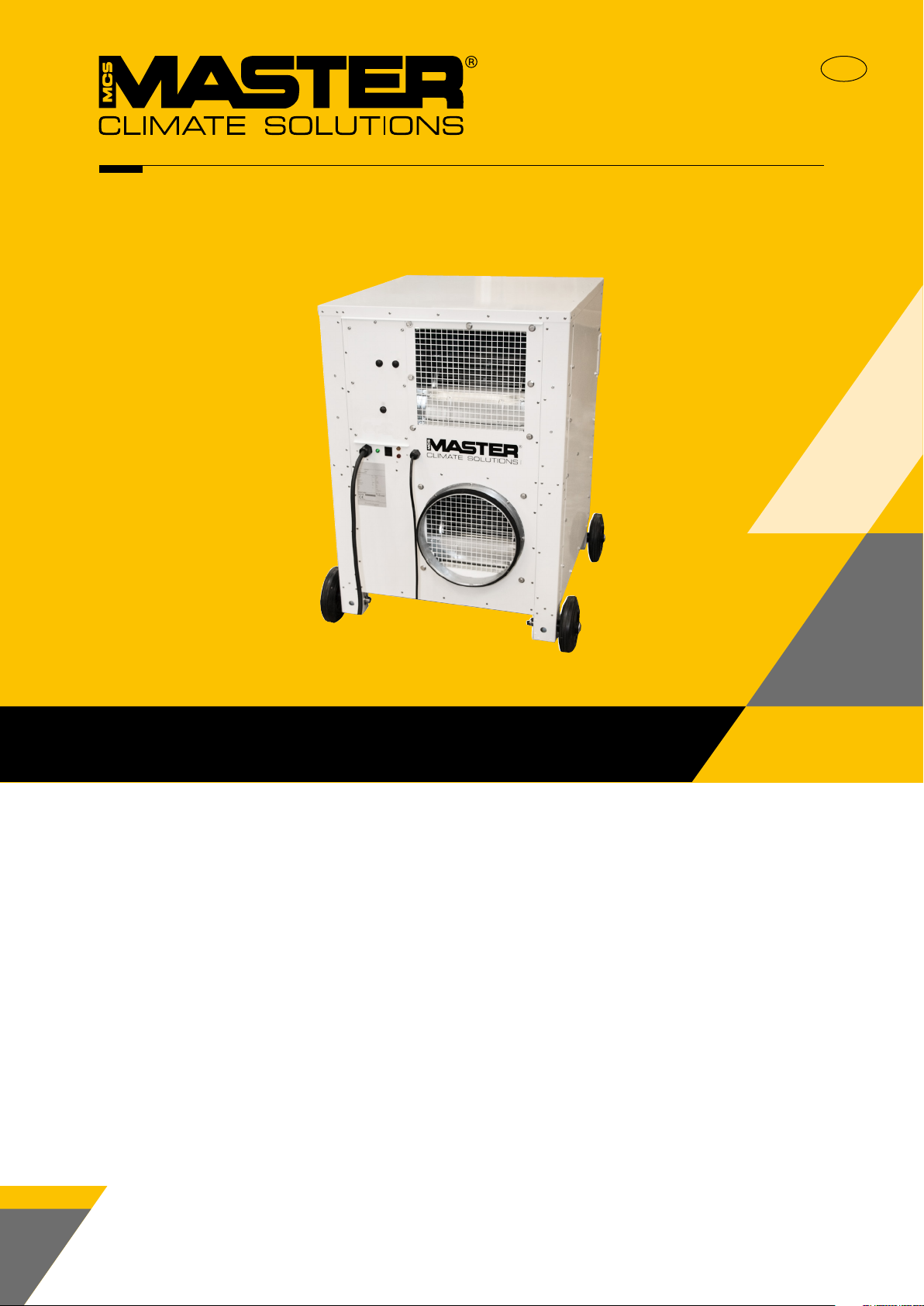
AC 24
Installation manual
Rev. 1.0
EN
Rev. 1.0
Page 2
Declaration of Conformity
Dantherm S.p.A
Marienlystvej 65
DK - 7800 Skive
Tel.: +45 96 14 37 00
Fax: +45 96 14 38 00
Declaration of following product:
Product name: AC 24
Product no.: 323043
EN
Dehumidication
The product is in conformity with the following directives:
2006/42/EC Machinery Directive
2014/35/EU Low Voltage Directive
2014/30/EU EMC Directive
2014/68/EU Pressure Equipment Directive
2011/65/EU RoHS Directive
1907/2006/EC REACH Regulation
- and is manufactured in conformity with the following harmonised standards:
DS/EN ISO 12100-1:2011 Safety of machinery - General principles for design
EN 60204-1 Safety of machinery - Electrical equipment of machines - Part 1
EN 60 335-1:2012 Household and similar electrical appliances - Safety - Part 1:
EN 60 335-2-40:2003 Household and similar electrical appliances - Safety - Part 2-40
DS/EN 61000-6-2:2005 Electromagnetic compatibility (EMC) - Part 6
DS/EN 61000-6-3:2007 Electromagnetic compatibility (EMC) - Part 6
Skive, 20/08-2018
Product manager
Lars Brodersen
VP Sales
Page 3
22.08.2018
Overview
Introduction This is the service manual for the Master AC-24 unit.
The below table of contents gives an overview of the main sections.
This manual is for the unit AC 24
Dantherm Number Code NSN
323043 AC-24-B-305-R9010 * 4120-22-631-1514
*) The code is specied on the data plate, which is placed on the control panel.
See the explanation of the syntax code on page 8
WARNING It is the responsibility of the operator to read and understand this service manual and other
information provided and to use the correct operating procedures.
Air conditioners should only be operated by qualied (trained) personnel and the repair of
!
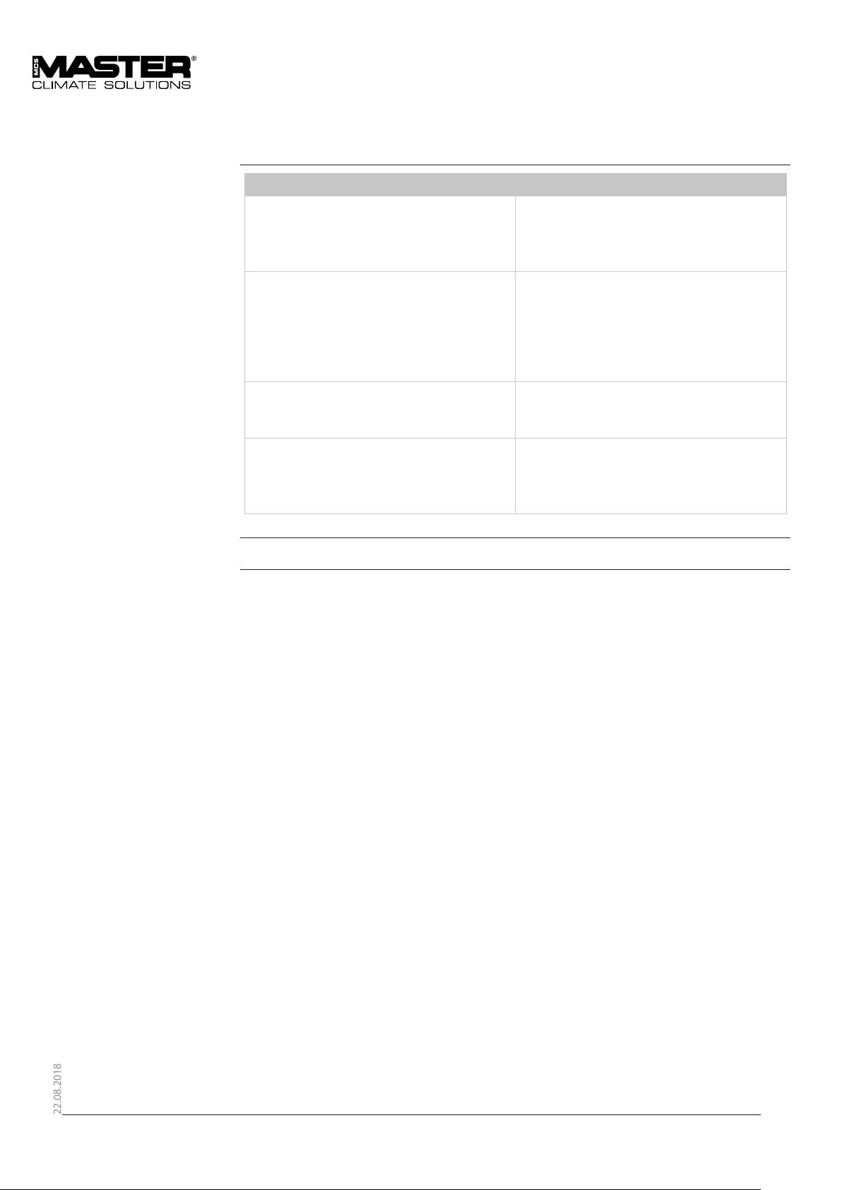
Table of main topics This service manual covers the following main topics:
the cooling circuit and electrical system is to be done only by skilled service people. Failure
to do so can result in personal injury or equipment damage.
Read the entire manual before the initial start-up of the air conditioner. It is important to
know the correct operating procedures for the air conditioner and all safety precautions to
prevent the possibility of property damage and/or personal injury.
Topic See page:
General information 4
Table of content 5
Product description 6
User’s guide 20
Service guide 29
Technical information 45
3
Page 4

22.08.2018
General information
Introduction This section gives the general information about this service manual and about the unit.
Target group • Users of the unit
• Technicians who install and maintain the unit
Part number Part number of this service manual is 097881
Copyright Copying of this service manual, or part of it, is forbidden without prior written permission from
Master.
Reservations Master reserves the right to make changes and improvements to the product and the service
manual at any time without prior notice or obligation.
Recycling The unit is designed to last for many years. When the time comes for the unit to be recycled, the
unit should be recycled according to national regulation to protect the environment.
Quality Management
System
Dantherm S.p.A has implemented a Quality Management System according to EN/ISO9001.
The system is supplemented with an Environmental Management System according to EN/
ISO14001. Both systems are approved by third party and certied, by Bureau Veritas Certication.
During 2005 & 2006 the Management Systems were supplemented with business routines
with regards to safety. These routines meet the requirements stated in the international
standard for Safety Management Systems OHSAS18001.
4
Page 5
22.08.2018
Table of contents
Table of content
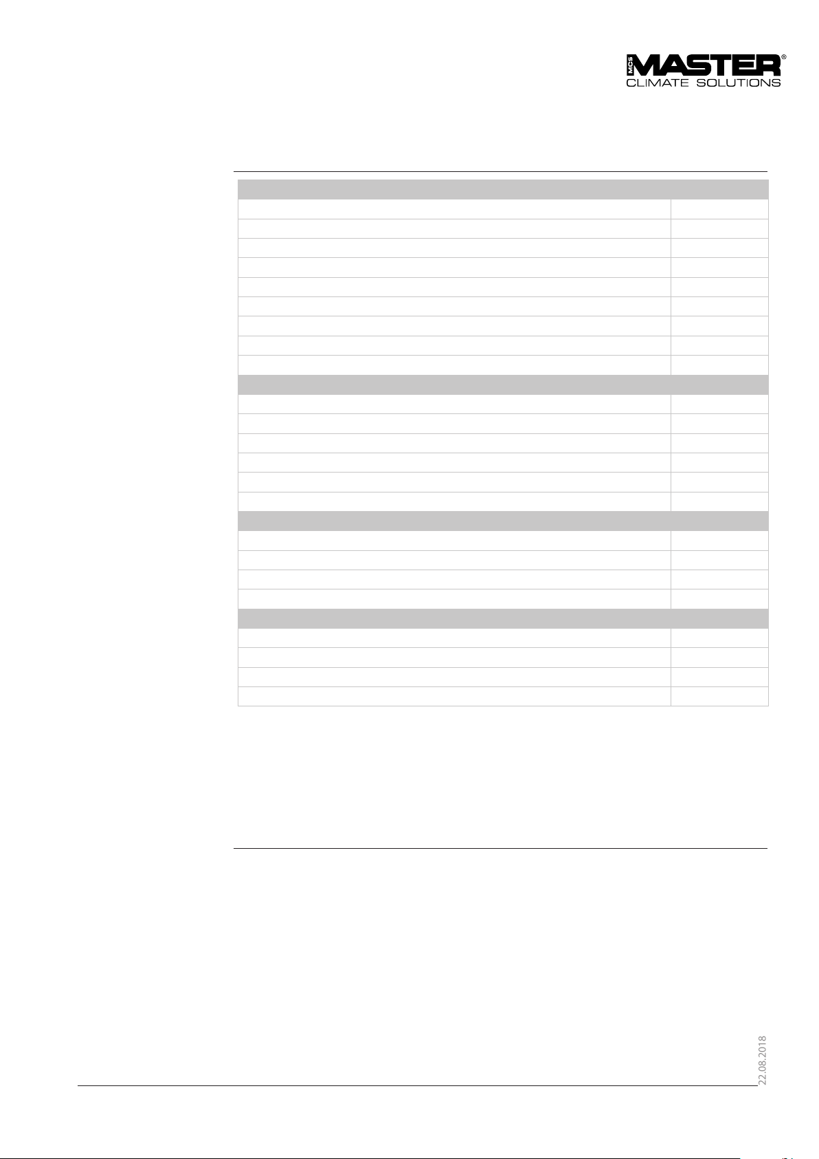
Product description See page
General description 8
Transport of the unit 8
Description of parts 8
Syntax 9
Description of the cooling system 10
Description of the control board 15
Description of room thermostat 17
Description of the high and low pressure switch function 18
Functional Description 19
User´s guide
Preparations 21
Setup 22
Recommended camp conguration 23
Transport of the unit 26
Starting up and shutting down the air conditioner 27
Reset of thermo relay and control circuit fuse 28
Service guide
Preventive maintenance 30
Spare parts 33
Fault nding guide 41
Service agreement 43
Technical information
Technical data 45
Dimensions 46
Wiring diagram, AC 24 47
Wiring diagram reference 49
5
Page 6
22.08.2018
Product description
Introduction This section will give you a description of the AC 24 and its functionality.
Content The section covers the following topics:
Topic See page
General description 8
Transport of the unit 8
Description of parts 8
Syntax 9
Description of the cooling system 10
Description of the control board 15
Description of room thermostat 17
Description of the high and low pressure switch function 18
Functional Description 19
6
Page 7

22.08.2018
General description
Introduction
General
Typical applications
Functionality
WARNING
This section describes the unit as a whole.
The following sections describe the dierent parts of the unit..
The AC 24 is a portable air conditioner that is made of high quality materials and the production process is
subject to constant quality checking. The instructions in this service manual have been prepared to ensure
that, when followed, this air condi-tioner will provide long and ecient service.
The AC 24 is designed primarily to supply cooled air to tents and other types of temporary portable
shelters.
The function of the unit is based on a cooling circuit and two powerful centrifugal fans. The lower section
contains the evaporator and the evaporator fan which draws warm ambient or recirculated air through the
cold evaporator coil and blows out the cooled air through the discharge.
The upper section of the unit houses the condenser fan and the condenser coil which returns the heat
taken from the cooled air to the surrounding atmosphere.
Do not cover, block or obstruct the air openings. This may cause malfunction!
Do not operate the product outside the specied temperature range.
See section “Technical data”.
7
Page 8
22.08.2018
General description, continued
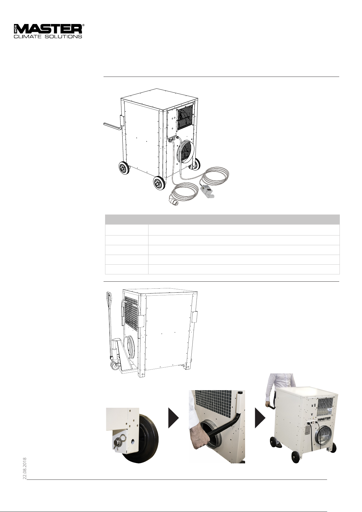
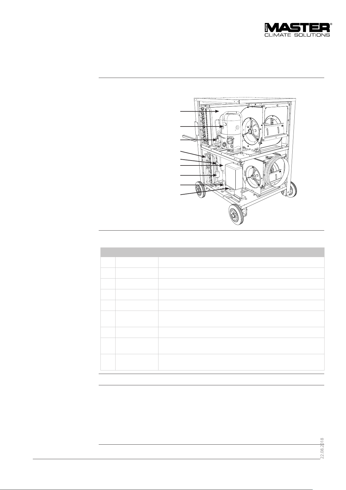
Illustration This illustration gives an overview of the unit.
Parts
Transport of the unit.
Item Description
1 Handlebars for transport ( Accessories)
2 Wheels for easy eld mobility of the unit (Accessories)
3 Control panel with function switch and lamps
4 Mains cable
5 Room thermostat
8
Page 9
22.08.2018
Syntax
Introduction
Example
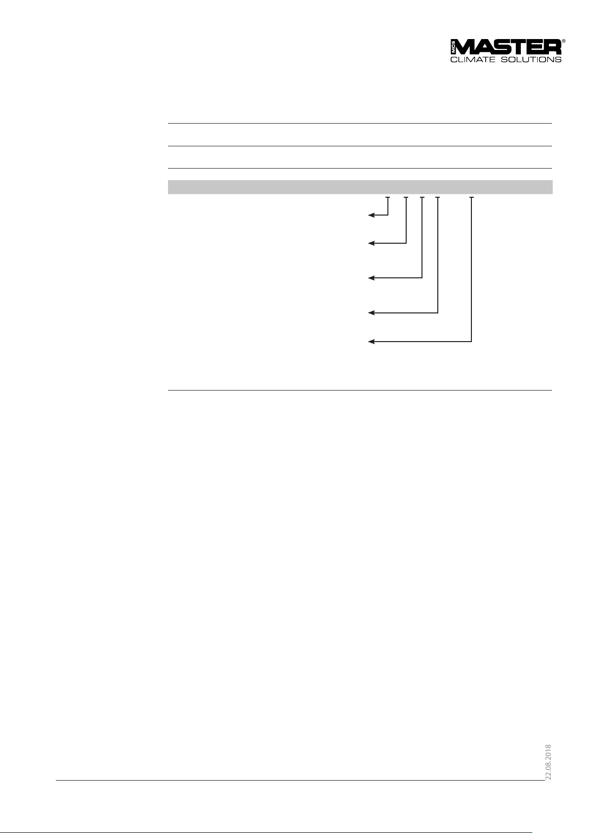
All products are named according to a syntax giving information about the specic unit conguration.
This example is not necessarily related to the specic unit this manual describes:
AC_24_B_305_R9010
AC Air conditioner
24 Nominal performance 24.000BTU/h
B 1ph; 230VAC; 50Hz
C 1ph; 230VAC; 60Hz
305 Duct connection size - mm
R RAL Color code
9
Page 10
22.08.2018
Description of parts
Introduction This section gives a description of the following parts of the AC 24:
• Cabinet • Fans
• Air lters • Mains cable
• Heating coil • Air openings
The following sections in this chapter give separate detailed descriptions of the cooling circuit,
the control board and operation.
For illustration of the single components – please see section “General description”
Cabinet The unit is made of strong construction in sheet metal plates which are galvanized to protect
against corrosion.
The outside paint nish is standard white, RAL 9010.
In the middle plate there is a drain outlet for condensate.
On each side of the unit a plate can be removed to make inspection and service possible.
Inside the unit there is a horizontal partition dividing it into an upper and a lower section.
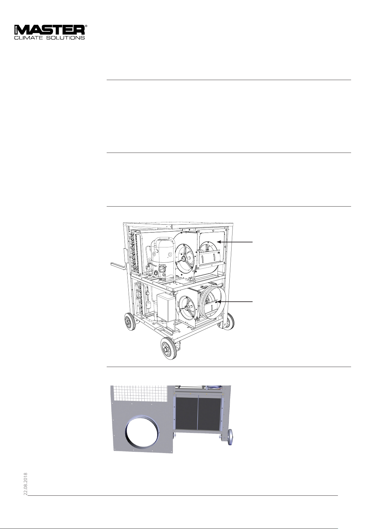
Fans In both upper and lower sections there is a centrifugal fan with a direct-coupled motor.
Condenser fan
Evaporator fan
Air lters The internal airow enters through a standard washable, easily removable air lter, PPI 15.
The lter is situated behind the return air inlet
The rods keeping the lter
in place are accessible
through the fan opening
without having to remove
the cover.
The airow will be inuenced by the resistance in lters, hoses and coils, which must be kept
clean to minimize the pressure drop.
10
Page 11

22.08.2018
Description of parts, continued
Mains cable The unit requires an external electric power source.
The mains cable is 10 m long and normally has a 16 A CEE connector at its end.
Air openings
Varm air outlet
Cold air intake
Cold air out
Hot Air intake
11
Page 12
22.08.2018
Description of parts, continued
Air openings, continued
WARNING Do not cover or obstruct air openings!
inlets/outlets Purpose
Supply air outlet,
1 × 315 mm
Return air inlet,
1 × 315 mm
Ambient air inlet Ambient air is ducted in through the
Exhaust air outlet Condenser exhaust air leaves the air
Air is supplied to the tent/shelter through
these openings.
Flexible air hose(s) will be connected here
Air is drawn into the unit through this/these
opening(s). With connected air hose(s) the
unit is supplied with recirculated return air
from the tent/shelter
Flexible air hose(s) will be connected here
condenser after entering the external
removable lter
conditioner
through these openings
12
Page 13
22.08.2018
Description of the cooling system
Illustration This drawing illustrates the dierent parts
of the cooling circuit and where
they are situated in the AC 24 unit:
Parts and their function This table gives an overview and short description of each part shown above and on
the next page:
Compressor Circulates the uid in the cooling system
Condenser Emits the heat generated in the tent/room to the outside air
Receiver Accumulates surplus coolant in connection with the cooling process
Dry lter Absorbs moisture and impurities in the cooling circuit
Sight glass Enables a visual check of the coolant
Expansion valve Supplies the correct quantity of coolant into the evaporator. It also
Evaporator Absorbs heat from the shelter by cooling down the circulated air
HP pressure
switch
LP Pressure
switch
Refrigerant The cooling circuit is hermetically sealed and lled with refrigerant (R134a).
Liquid ow
From the receiver liquid refrigerant will ow under high pressure through the liquid line
dryer and the sight glass to the thermostatic expansion valve which releases the pressure. Here
the refrigerant is led into the evaporator where it evaporates under low pressure and low
temperatures.
The evaporated refrigerant is drawn back to the hermetic compressor and compressed. From
the compressor the refrigerant vapour goes to the condenser, where it is cooled to below the
dew point and condensed to liquid refrigerant.
reduces the pressure
Ensures that the compressor does not operate at too high pressure
Ensures that the compressor does not operate at too low pressure
13
Page 14
22.08.2018
Description of the cooling system, continued
Description Both evaporator and condenser are heat exchangers with copper tubes and aluminium coated
ns. By the cooling of the evaporator air stream heat is adapted to the cooling circuit and
released in the condenser together with the electric energy consumption of the compressor.
At room temperatures below 20 °C, where cooling is not normally required, the humidity in
the airow will form ice on the evaporator. To prevent this, the LP pressure switch cuts out
at low pressure in the circuit. If the room temperature is too low, the LP activation will cause
the compressor to start and stop frequently. This may damage the compressor and must be
avoided at any time by not operating the product outside the specied temperature range. See
section “Technical data”, page 54. At high ambient temperatures (above 55 °C) the cooling of the
condenser airow will be too poor, and the high pressure results in cut out of the HP pressure
switch.
The yellow lamp on the front panel will illuminate if the HP/LP pressure switch cuts out. The HP/
LP pressure switch automatically resets after a few minutes and the lamp will switch o again. If
the lamp continues to illuminate, please refer to the “Fault nding guide”, page 50.
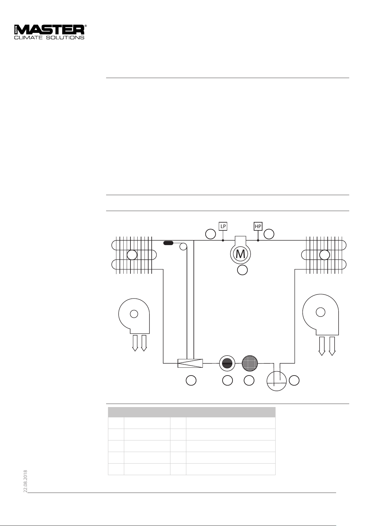
Schematic view This schematic drawing illustrates the dierent parts of the cooling circuit.
9 8
7
Compressor
Condenser
Receiver
Dry lter
Sight glass
Expansion valve
Evaporator
HP pressure switch
LP pressure switch
2
1
3456
14
Page 15
22.08.2018
Description of the control board
Introduction This section gives a description of the control board.
A description of how to start up, for example, is found in the relevant sections.
The control panel on the front contains the controls required for normal operation.
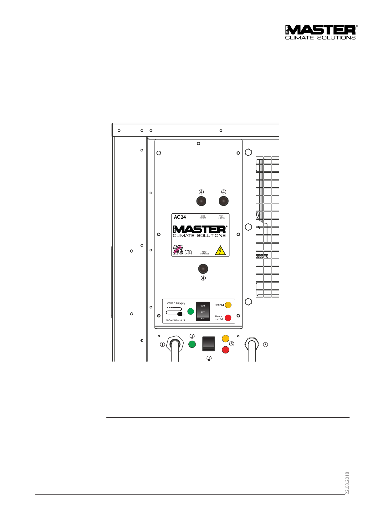
Illustration This drawing illustrates the control board of the AC 24:
15
Page 16
22.08.2018
Description of the control board, continued
Part/function This table gives an overview of each part of the control panel in g. 6:
No
Part Function
Electric
connection
Function
switch
Indicator
lamps
Mains cable with a 16 A CEE connector at the end
The function switch selects the operating mode and has three positions:
VENT, OFF and AUTO
On the operator panel there are three control lamps, indicating the
following:
Color Unit Description
Green Power Shows that power has been connected to the unit
Red Thermo
relay fail
Illuminates if the compressor, evaporator fan or
condenser fan thermo relay has cut o because of a
too high running current.
Please also refer to the “Fault nding guide”
Yellow HP/LP Illuminates when the built-in HP/LP pressure switch
cuts out and stops the com-pressor because of too
high pressure (HP) or low pressure (LP) in the cooling
circuit. The HP/LP pressure switch automatically
resets after a few minutes. Do not let the product
operate with HP/LP switching ON and OFF.
If the lamp continues to illuminate, please refer to
the “Fault nding guide”
Reset
button
•Compressor
•Evaporator fan
•Condenser fan
Thermostat
connection
If the failure indicator (Thermo relay ) illuminates, the thermo relay will
have to be reset on one of the reset buttons.
If it is not clear which one of the thermo relays has disconnected, push the
reset buttons one by one.
See also “Fault nding guide”
Cable for the remote thermostat
16
Page 17

22.08.2018
Description of room thermostat
Introduction This section gives a detailed description of the room thermostat.
Illustration This drawing illustrates the dierent
parts of the room thermostat:
Sensor
Parts and their function
Location The thermostat must be placed inside the tent.
No Part Function
Knob Setting of the temperature
Scale Shows the temperature setting
Scale Shows the dierential temperature setting
14 m cable -
See more about the placement in section “Set-up”
17
Page 18

22.08.2018
Description of the high and low pressure switch function
Introduction This topic describes the HP/LP function.
System protection The cooling system is protected by pressure switches. If the pressure falls outside of the
normal operating range, the air conditioner compressor is automatically switched o. This is to
prevent component damage. If the pressure is too high or too low, the unit is switched o. The
malfunction must normally be identied by a trained technician and corrected.
Reset The HP/LP pressure switch automatically resets after a few minutes.
If the lamp continues to illuminate, please refer to the “Fault nding guide”.
LP (low pressure) The cooling system is protected by a low-pressure switch (LP switch). The switch is set at 1 bar
and will automatically reset at 2.5 bar. The safety function cuts o the com-pressor.
The LP function will be activated if:
• The cooling system loses refrigerant
• The internal temperature is so low that the low pressure gets below set point (1 bar).
Do not operate the product with frequent operating LP function.
• The evaporator is blocked or does get not sucient air ow
HP (high pressure) The cooling system is protected by a high-pressure switch (HP switch). The switch is set at 25 bar
and will automatically reset at 18 bar. The safety function cuts o the compressor.
The HP function will be activated if:
• The outdoor temperature is too high
• The condenser is blocked or does not have sucient airow
18
Page 19

22.08.2018
Functional description
VENT
Ventilation-only operation
AUT. or AUTO
Room thermostat operation,
cooling/heating (if installed)
OFF or 0 OFF
With the function switch in this position the evaporator fan will operate continuously and the
cooling unit, heating coil (if installed) and condenser fan will be turned o.
This mode can be used to bring in fresh outdoor air or to recirculate the indoor air - even when
cooling or heating (if installed) is not needed.
With the function switch in this position, the unit will operate according to the room thermostat
settings.
On the AC 24 with heating coils the room thermostat has a ip switch with the following
positions:
• Cool
With the ip switch in the cool position, the unit will cool as long as the thermostat senses a
temperature higher than the set point. When the temperature reaches the set point it cuts o
the compressor and fans.
With the function switch in this position all functions will stop immediately and only the
illuminated green lamp will indicate that the power is still on if the main switch is on.
19
Page 20

22.08.2018
User’s guide
Introduction This section describes how to utilise the dierent functions.
WARNING Do not try to restart the compressor several times within a short period.
This will make the compressor overheat and may damage it. The internal compressor
thermostatic protection may also cut out.
Operating the product outside the temperature range specied in the technical data will
cause the cooling system to start frequently.
Do not operate the product at temperatures outside the specications.
Warning If forklift (MHE) is to be used it is imperative that the tine is fully engaged, thereby supporting
the entire unit. Rough and incorrect handling can cause damage and loss of function.
Contents This User`s guide contains the following topics:
Topic See page
Preparations 21
Setup 22
Recommended camp conguration 23
Transport of the unit 26
Starting up and shutting down the air conditioner 27
Reset of thermo relay and control circuit fuse 28
20
Page 21

22.08.2018
Preparations
Location Follow these conditions when siting the air conditioner:
Conditions
Place in the shade as close as possible to the tent/shelter that needs to be ventilated
Place the air supply ducts in both ends of the tent/shelter
Allow sucient space around the air conditioner for operating and servicing access
Avoid sharp bends or kinking when locating air supply ducts in order to avoid disrup-tion of
the airow (see “Recommended camp conguration”, page 23)
Keep any source of engine exhaust fumes (vehicles/generators etc.) away from air in-takes
Air distributing channels It is imperative that the cooled air is distributed equally inside the tent/shelter. For that purpose
the use of air distributing hoses are recommended (accessory).
Power The air conditioner requires 1 x 230 V AC/50 Hz.
The mains cable is 10 m long and has a 16 A CEE connector at the end.
Note The maximum combined length of exible air hoses should not exceed 9-10 m.
21
Page 22

22.08.2018
Setup
Procedure
Step Action
1 Find a suitable location for the air conditioner as described on previous page.
2 Supply ducts.
Connect the exible insulated air hoses to the evaporator discharge openings and
insert the opposite end of the hose to the tent. If there are any internal distribution
hoses in the tent, these can be connected too
3 Return ducts.
A return air hose may be connected from the shelter to the evaporator air inlet. As
long as the return air is colder than the ambient air this will save cooling capacity
4 Place the room thermostat inside the tent/shelter at the optimal location
• Avoid sunlight
• Avoid direct cold air from the air conditioner ducts
• 1.5 m above the oor
• Near the return air end of the tent/room
5
• Set the desired temperature
in the shelter by pressing the
buttons on the thermostat.
In cooling mode – do not
require less than 20ºC which
would make the unit operate
outside its´ specied limits.
6 Check that the function switch is set at “0” or „OFF“
7 Check that the power switch is OFF
8 Connect the CEE plug to the external power source and switch on
22
Page 23

22.08.2018
Recommended camp conguration
Introduction The conguration is an important factor for gaining the highest performance and reliability from
the air conditioner including lowest power consumption. A camp can be set up in various ways
and still work, but a few important hints will be given in this section.
This section describes the following:
• Ducting
• Solar heat
• Air distribution
• Sand storms
• Air re-circulating
Ducting The ducts will introduce a pressure loss every
time they are bent. Slight bends are not as
critical as tight bends > 45°.
The shorter the ducts the higher performance
frmo the air conditioner.
In some cases the tent does not allow for
ducting as per the air conditioner design. Be
aware that blocking one or two of the duct
holes on the air conditioner will reduce the
cooling performance signicantly.
Use as few ducts as possible. As a rule of
thumb expect that each 3 m insulated duct
changes the temperature inside the duct by
3-5 °C (6-10 °F).
Solar heat Solar heat gain to shelter surfaces and to duct-/air conditioner reduces the eciency of the
unit. If possible use a sun shield to cover the shelter, the air conditioner, and the associated air
ducting. Additional eciency is gained by using insulated panels/liners in the shelter.
• Doors and openings
• Heat sources
• Surroundings
• Drains
23
Page 24

22.08.2018
Recommended camp conguration, continued
Air distribution In cases where air distribution plenums are used for distributing the internal cooled air, it can be
an advantage if the plenum is located under the roof.
The cold air will slowly fall to ground and be sucked back into the air conditioner.
Sand storm In case of sand storms it is important that the air conditioner is shielded against the sand.
Do not shield to the extent where the air ow will become obstructed.
Air re-circulating In order to cool down the air most eciently, the air being introduced to the air conditioner
must be as cold as possible. If the room temperature is lower than the am-bient temperature
outside, it is most ecient to re-circulate the air from the room. To do so, connect insulated
ducts between the tent and the air conditioner internal air in-take.
If the tent temperature is higher than the ambient temperature, it can be an advantage to
operate without return ducts. Also be aware of the dust risk and generation of over pressure in
the tent.
24
Page 25

22.08.2018
Recommended camp conguration, continued
Doors and openings In order to achieve best performance it is imperative that doors and openings are kept closed.
Heat sources Heat producing sources will degrade the eciency of the air conditioner and thus non-
essential heat sources should be turned o whenever possible.
Surroundings Do not cover, block or obstruct the air path. Make sure that the air conditioner is clear of
obstruction on all sides allowing air to be drawn in and exhausted out freely.
25
Page 26

22.08.2018
Recommended camp conguration, continued
Drain Water draining from the evaporator will saturate the area around the drain outlet. Pay attention
to this potential problem and route away condensate if necessary. If possible raise the air
conditioner above ground level by use of a pallet or other suitable means.
WARNING
Do not park vehicles where exhaust gases can be drawn into the air intake of the AC-24
26
Page 27

22.08.2018
Starting up and shutting down the air conditioner
Start up After preparation and set-up the air conditioner is ready for operation.
Turn the function switch to the desired mode (see “Description of the control board”, page 14)
and the unit will operate according to the “Functional description”,
Fault If the unit does not operate it might have been switched o by a safety device:
• HP pressostat: High ambient temperature stopped condenser fan or reduced airow
over the condenser
• LP pressostat: Low return air temperature stopped evaporator fan or reduced airow
over the evaporator
• Evaporator or condenser thermo relay: Running current for fan motor too high
• Compressor thermo relay: running current for compressor too high
• ETA relay: running current for control current too high
Refer to the “Fault nding guide”, for possible solutions.
WARNING Do not attempt to repeatedly restart the compressor.
This will cause the compressor to overheat and may damage it.
The internal compressor thermostatic protection may also cut out.
Shutting down Follow this procedure to shut down the air conditioner from any mode of operation:
1. Turn the function switch to OFF/0
Result: All operations will stop immediately
2. Disconnect the connector from the power source if any servicing has to be performed.
If the air conditioner is not to be re-used for a long period, continue shutting down as
follows:
3. Disconnect the air ducts and stow them in their compression sacks.
27
Page 28

22.08.2018
Reset of thermo relay and control circuit fuse
Introduction The procedures below describe how to reset the thermo and replace the control circuit fuse.
Thermo relay If the running current for the compressor, condenser fan or evaporator fan exceeds the set value,
the thermo relay will switch o the compressor or fan and will have to be reset.
Reset Thermo relay Push the buttons one by one in no particular order to reset the thermo relay.
See buttons marked with arrows below.
Control circuit fuse If the running current for the control circuit is too high, the fuse will blow, and will have to be
replaced. See location below.
28
Page 29

22.08.2018
Service guide
Contents
Topic See page
Preventive maintenance 30
Spare parts 32
Fault nding guide 40
Service agreement 42
29
Page 30

22.08.2018
Preventive maintenance
Introduction In order to achieve the best possible operation and long lifetime of the air conditioner it has to
be maintained properly within dened guide lines.
This section contains the description of daily, monthly and annual maintenance.
Tools For service and maintenance no special tools are required.
A 10 mm spanner and a at headed screwdriver are sucient for most maintenance tasks.
CAUTION Before doing any maintenance, be sure that the air conditioner has been shut down and that
the power cable is disconnected from the unit.
See section “Starting up and shutting down the air conditioner”
Daily preventive
maintenance
Daily preventive
maintenance
Preventive maintenance to be carried out daily or every 8 hours of operation:
After shutdown each day or after every eight hours of operation perform the following
preventive maintenance procedures:
Preventive maintenance to be carried out daily or every 8 hours of operation:
After shutdown each day or after every eight hours of operation perform the following
preventive maintenance procedures:
Step Action
1 Inspect electrical cables for damage or loose connections
2 Inspect the air lter and remove any debris or foreign objects that may have
accumulated on lters.
3 Inspect air hoses for damage or sharp bends
30
Page 31

22.08.2018
Preventive maintenance, continued
Monthly preventive
maintenance
Step Action
1 Perform daily maintenance as described on previous page.
2 Remove the air lter which have to be vacuum cleaned or washed in lukewarm soapy
water.
The evaporator lter is easily removed. In order to remove the lter material, Remove
the three exible plastic rods holding the lter in place . Access the rods through
the duct hole. Make sure that the lter is dry before it is returned to service and are
subjected to dust.
Annual preventive
maintenance
3 Remove the two side cover plates and inspect the evaporator and condenser coils.
If they are dirty vacuum clean or wash with warm soapy water and a brush
4 Check that the condensate drain is not blocked
5 Inspect and clean the radial wheels in the two fans if necessary
Step Action
1 Perform daily and monthly maintenance as described
2 Have a refrigerant mechanic check the cooling circuit and all electrical functions
This control must follow the national rules for control of cooling equipment.
31
Page 32

22.08.2018
32
Page 33

22.08.2018
Spare parts
Introduction This section contains the general information needed when ordering spare parts.
For units in military services spares will normally be ordered through the military logistic
system.
When ordering When ordering, kindly inform us about:
• Dantherm S.p.A. spare parts number/text
• NATO stock number of parts
• Dantherm S.p.A. eld unit type
• Dantherm S.p.A. production and serial number from the data plate of the eld unit
(or approximate date of delivery).
Information If it is part of a group naturally forming a whole or part of a purchased, complete component,
ome items may not be available for individual delivery.
Dantherm S.p.A reserve the right to make this assessment.
Reservations Dantherm S.p.A. reserve the right to make any necessary changes of construc-tion and choices
of components without notice - but will, as far as possible, maintain a stock of the changed
parts.
Contents
Topic Page
Spare parts for cabinet 34
Spare parts for cooling system 36
Spare parts for controller 38
Accessories 40
33
Page 34

22.08.2018
Spare parts for cabinet
Illustration Available spare parts
1.6
1.9
1.7
1.3
1.8
1.5
1.4
1.1
1.2
1.3
34
Page 35

22.08.2018
Spare parts for cabinet
Cabinet
Cabinet Art.No. Name NSN
1.1 098820 Sideplate right/left 4130-22-632-1603
1.2 098822 Rear plate with hose connection 4130-22-632-1606
1.3 098823 Hose connection 5999-22-632-1609
1.4 098824 Filter mounting 5340-22-632-1612
1.5 081579 Filter 4130-22-632-1614
1.6 093803 Roomthermostat complete. 5930-22-632-1619
1.7 081582 Condenser fan 4140-22-632-1622
1.8 075499 Evaporator fan 4130-22-632-1626
1.9 098830 Front for controller 4130-22-632-1664
35
Page 36

22.08.2018
Spare parts for Cooling system
Illustration Available spare parts for cooling system
2.1
2.32.2 2.4
36
2.5
2.6 2.7 2.8 2.9
2.10
2.2 2.11
Page 37

22.08.2018
Spare parts for Cooling system
Cabinet
Cabinet Art.No. Name NSN
2.1 081580 Condenser coil 4130-22-632-1665
2.2 063125 Service valve 4820-22-632-1667
2.3 298976 Low Pressure switch (LP) 5930-22-632-1668
2.4 098840 Compressor cpl. 4130-22-632-1670
2.5 091283 Evaporator coil 4130-22-632-1672
2.6 081631 Thermostatic valve 4820-22-632-1677
2.7 063123 Sight glass 6680-22-632-1679
2.8 298974 Filter drier 4130-22-616-3541
2.9 063128 Reciver 4130-22-632-1682
2.10 098868 Capacitor for Compressor 5910-22-632-1683
2.11 086414 High Pressure switch (HP) 5930-22-632-1684
Note: All spare parts for cooling system includes lter drier.
37
Page 38

22.08.2018
Spare parts for Controller
Illustration Available spare parts for controller
3.1
3.2 3.3
3.5
3.4
3.10
3.6
3.7
3.8
3.9
3.12
3.11
38
Page 39

22.08.2018
Spare parts for Controller
Cabinet
Cabinet Art.No. Name NSN
3.1 081686 Transformer 6120-22-632-1689
3.2 098858 K1 - Contactor Cpl. 6110-22-632-1709
3.3 098859 K2 - Contactor Cpl. 6110-22-632-1710
3.4 098860 K3 - Contactor Cpl. 5945-22-632-1712
3.5 098861 Fuse Block 5920-22-632-1713
3.6 098862 Fuse 10 pcs. 5925-22-632-1714
3.7 098863 Terminal block cpl. 5940-22-632-1726
3.8 098864 Controller front 1670-22-632-1727
3.9 064274 Cable gland set 5975-22-620-1668
3.10 091287 Controller for Roomthermostat 4130-22-632-1696
3.11 091288 Sensor for Roomthermostat 6685-22-632-1698
3.12 098865 Power supply cable 6150-22-632-1699
39
Page 40

22.08.2018
Accessories
Accessories
Art. No. Description Illustration
096673 Wheel set and handles
097754 Hose Ø320mm L. 3000mm
097756 Air distribution hose
Ø320mm L. 5000mm
098108 Hose ties
3x
Nato Stock Number
4520-22-631-7709
2x
4x
4720-22-631-7710
4720-22-631-7163
5340-22-631-7711
093894 Handles
5340-22-631-7708
2x
40
Page 41

22.08.2018
Fault nding guide
Fault nding Malfunctions that might occur in the operation of the air conditioner are listed in the table
below. Reference to actions required to restore the air conditioner to normal op-erating
condition are also indicated.
If the air conditioner should malfunction, nd the problem in column 1. Columns 2 and 3
describe the possible causes and corrective actions. The list of problems, causes, and remedies
will only give an indication of where a possible problem can be and what actions are needed to
correct the problem.
Problem Cause Action
Air conditioner does not
operate
Green indicator lamp on
control panel is not ON
No power input Check that the power cable is
correctly connected to power
source and unit. Check that
power source is turned on and
providing 1 x 230 V AC
Controller fuse is blown. Replace fuse.
Location shown on page 27
Air conditioner (compressor)
does not operate.
Green and yellow HP/LP
indicator lamps are on, but
they switch o again after a
few minutes
Air conditioner (compressor)
does not operate.
Green and yellow HP/LP
indicator lamps are on, and
they do not switch o after a
few minutes
Compressor does not operate
Green and red THERMO RELAY
indicator lamps are on
High ambient temperature
resulting in HP pressure switch
cut-out
Reduced condenser airow
perhaps combined with
ambient temperature just
below 55 °C
Reduced evaporator airow
perhaps combined with low
ambient temperature resulting
in LP pressure switch cut-out
Faulty thermostatic valve A refrigeration engineer has to
Refrigerant leak on the cooling
circuit
Compressor thermo relay has
cut o
The HP pressure switch will
automatically reset when
the ambient temp. has fallen
below 55 °C.
Hereafter the unit will restart
Clean evaporator coil and
airow lter Check that the
grill at the air outlet are not
blocked
replace the valve.
A refrigerant engineer has to
check on the problem
Press the reset button for
compressor on the control
panel (see section “Reset of
thermo relay”, page 27)
41
Page 42

22.08.2018
Fault nding guide, continued
Fault nding, continued
Condenser or evaporator fan
does not operate.
Green and red thermo relay
indicator lamp are on
WARNING Do not try to restart the compressor several times within a short period. This will overheat
and may damage the compressor. The internal compressor thermostatic protection may also
cut out.
High ambient temperature If the surrounding temperature is higher than the max working temperature: 55 °C, the
condenser will not be cooled enough, resulting in too high pressure in the cooling circuit and
thereby operating the pressure switch (HP). Allow some time for cooling of the system.
Low ambient temperature If the air conditioner is operating below 20 °C the humidity in the airow can form ice in the
evaporator coil. As the ice is insulating, the pressure in the cooling circuit will decrease until the
pressure switch (LP) operates. In this case the mode selector should be turned to ventilationonly so that the evaporator coil can be defrosted by the airow.
Reduced airow A reduced airow can be caused by dirty lters or sharp kinks in the air hoses etc.
This can result in activation of the pressure switch (LP). Check the unit.
Problem Cause Action
Fan thermo relay has cut o Press the reset button for
the evaporator or condenser
fan on the control panel (see
section “Reset of thermo",
page 28)
42
Page 43

22.08.2018
Service agreement
Introduction The unit includes mechanical and electrical parts and the unit is often placed in a rough
environment where the components are exposed to dierent climate conditions. Therefore
the unit will need preventative maintenance on a regular basis.
The After Sales Support Department of Dantherm S.p.A. is ready to help you
in case of a problem.
To be able to oer quick and ecient help, please have the following information ready
when contacting Dantherm S.p.A. :
• Name • Phone no. • Site/location (unit)
• Company • Email • Serial no/order no.
• Country • Type (unit) • Description of the problem
Contact Dantherm S.p.A. and ask for the After Sales Support department and help
will be provided as soon as possible:
Phone: +45 96 14 37 00
Fax: +45 96 14 38 00
Email: service@dantherm.com
Preventive maintenance Dantherm S.p.A. oers to do the preventive maintenance on the units so that they at all times
will operate according to factory standards.
Corrective and
emergency repair
Setup Dantherm S.p.A. has established a network of service partners to do the preventative
Further information For further information about a service agreement in your country or region, please contact:
In case of malfunctions of the product Dantherm S.p.A. oers to do emergency repair on the
climate units. Agreements will be made with the customer on response time and price.
maintenance. The partner is trained and certied on the actual climate units. The partner will
also carry an adequate number of spare parts – so that any repairs can be made during the
same visit.
The agreement will be made with Dantherm S.p.A. – and the overall responsibility for the
agreement belongs to Dantherm S.p.A.
Claus Havboe Rasmussen
After Sales Manager
Dantherm S.p.A.
Phone: +45 9614 3725
Mobile: +45 6168 1233
Email: Claus.Rasmussen@dantherm.com
43
Page 44

22.08.2018
Technical information
Overview This section provides technical information about the AS 24 and covers the following topics:
Contents
Topic See page
Technical data 45
Dimensions 46
Wiring diagram, AC 24 47
Wiring diagram reference 49
44
Page 45

22.08.2018
Technical data
Introduction Technical data for the AC 24 units.
*Note: All data regarding heating is only relevant for models with heating coil installed.
Performance
characteristics
The air conditioner has a maximum cooling capacity of 6.0 kW.
When the relative humidity of the air inlet is high, the air can be cooled below its dew point and
thus condense some of the water vapour to free water. This requires a certain amount of latent
cooling but provides a dehumidication process, which is an important factor in comfortable air
supply conditions.
The operating range is between 20 and 55 °C approximately and is controlled by the HP/
LP-pressure switch. In relatively dry locations the air temperature drop will depend on inlet
conditions.
Data Data and dimensions on the cabinet are shown in the following table:
Specication Designation Value 6,0 kW
Dimensions Height × width × depth
- mm
Weight kg 162
Cabinet material 0.9 mm galvanized sheet
Packaging - Wooden pallet and
Voltage supply V/PH/Hz 230/1/50
Max current Amp 16A
Airow, evaporator,
Standard setup2)
Cooling capacity, max W 6.000
m/h 2,800
1110 x 754 x 920 mm
metal plates
cardboard
Refrigerant/Load Type/kg R134a/2,3
Max. refrigerant pressure Bar 25
Operation temp. range C° 20-55
Minimum room
temperature setting
GWP
(Global Warming potential)
IP 55
Locked rotor amperange
(LRA)
C° 20
1430
A 46
45
Page 46

22.08.2018
Dimensions
Dimensions
46
Page 47

22.08.2018
Wiring diagram
Wiring diagram
47
Page 48

22.08.2018
Wiring diagram, Continued
Wiring diagram, continued
48
Page 49

22.08.2018
References
References The following references refer to the wiring diagrams on the previous pages:
Reference Description Reference Description
A El. Heating coil K1 Contactor evaporator fan
B3 HP pressure switch K2 Contactor condenser fan
B4 LP pressure switch K3 Contactor compressor
B2 OT thermostat el. heating coil K4 Contactor heating coil
B1 Limit thermostat el. heating coil K5 Timer (After run) el. heating coil
C1 Evaporator fan motor condenser M1 Evaporator fan motor
C2 Condenser fan motor condenser M2 Condenser fan motor
F1 Evaporator fan motor thermo
relay
F2 Condenser fan motor thermo
relay
F3 Compressor thermo relay S1 Function switch
H1 Green lamp “M ains” T1 Transformer
H2 Red lamp “Thermo relay” XRT Thermostat plug
H3 Yellow lamp “HP/LP” XT Control current breaker
M3 Compressor
RT Room thermostat
Master can accept no responsibility for possible errors and changes.
49
Page 50

22.08.2018
50
Page 51

22.08.2018
51
Page 52

Dantherm S.p.A.
Via Gardesana 11
37010
Pastrengo, Italy
t. +39 045 6770533
info@mcsitaly.it
Dantherm Sp. z o.o.
ul. Magazynowa 5a
62-023 Gądki Poland
t. +48 61 65 44 000
office@mcs-ce.pl
Dantherm LLC
Transportnaya 22/2
142800, Stupino
Moscow, Russia
t. +7 (495) 642 444 8
info@mcsrus.ru
Dantherm SP S.A.
C/Calabozos,
6 (Poligono Industrial)
28108 Alcobendas
Madrid Spain
t. +34 91 661 45 00
euritecsa@euritecsa.es
MCS China
Unit 2B, No. 512 Yunchuan Road Baoshang,
Shanghai,
201906 China
t. +8621 61486668
office@mcs-china.cn
Dantherm Group S.p.A
Marienlystvej 65
7800 Skive
Denmark
t. +45 99 14 90 00
Dantherm AB
Fridhemsvagen 3
602 13 Norrkoping
Sweden
t. +46 (0)11 19 30 40
Lars Skou Nielsen
Dantherm S.p.A
Marienlystvej 65
7800 Skive
Denmark
t. +45 96 14 37 00
Dantherm GmbH
Oststrase 148
22844 Norderstedt
Germany
t. +49 40 526 8790
Dantherm Ltd.
Unit 2, Galliford Road
Maldon CM9 4XD
United Kingdom
Dantherm AG
Im Vorderasp 4
8154 Oberglatt ZH
Switzerland
t. +41 44 851 51 51
Dantherm AS
Lokkeasveien 26
3138 Skallestad
Norway
t. +47 33 35 16 00
Dantherm Dubai
Suite #1009
Prism Tower,
Business Bay Dubai
United Arab Emirates
t. +971 56 831 7466
Data, descriptions and pictures are for indication only and absolutely not binding.
e Company reserves the right to modify or improve them without prior notice.
Master is a part of
 Loading...