

Page 1

MULTI SPLIT TYPE ROOM AIR CONDITIONER
INSTALLATION INSTRUCTION SHEET
(PART NO. 9369651014)
IMPORTANT!
Please Read Before Starting
This air conditioning system meets strict safety and operating standards. As the installer or service person, it is an important part of your
job to install or service the system so it operates safely and efficiently.
For safe installation and trouble-free operation,
you must:
• Carefully read this instruction booklet before beginning.
• Follow each installation or repair step exactly as shown.
• Observe all local, state, and national electrical codes.
• Pay close attention to all danger, warning, and caution notices
given in this manual.
WARNING
CAUSION
• Hazel alerting symbols
If Necessary, Get Help
These instructions are all you need for most installation sites and maintenance conditions. If you require help for a special problem, contact
our sales/service outlet or your certified dealer for additional instructions.
This symbol refers to a hazard or unsafe practice which can result in severe
personal injury or death.
This symbol refers to a hazard or unsafe practice which can result in personal injury and the potential for product or property damage.
Electrical
Safety alert
ENGLISH
When Transporting
••••••••••••••••••••••••••••••••••••••••••••••••••••••••••••••••••••••••••••••••••••••••••••••••••••••••••••••••••••••••••••••
Be careful when picking up and moving the indoor and outdoor units.
Get a partner to help, and bend your knees when lifting to reduce
strain on your back. Sharp edges or thin aluminum fins on the air
conditioner can cut your fingers.
When Installing...
••••••••••••••••••••••••••••••••••••••••••••••••••••••••••••••••••••••••••••••••••••••••••••••••••••••••••••••••••••••••••••••
...In a Ceiling or Wall
Make sure the ceiling/wall is strong enough to hold the unit’s weight.
It may be necessary to construct a strong wood or metal frame to
provide added support.
...In a Room
Properly insulate any tubing run inside a room to prevent “sweating”
that can cause dripping and water damage to walls and floors.
...In Moist or Uneven Locations
Use a raised concrete pad or concrete blocks to provide a solid, level
foundation for the outdoor unit. This prevents water damage and abnormal vibration.
...In an Area with High Winds
Securely anchor the outdoor unit down with bolts and a metal frame.
Provide a suitable air baffle.
...In a Snowy Area (for Heat Pump-type Systems)
Install the outdoor unit on a raised platform that is higher than drifting snow. Provide snow vents.
When Connecting Refrigerant Tubing
••••••••••••••••••••••••••••••••••••••••••••••••••••••••••••••••••••••••••••••••••••••••••••••••••••••••••••••••••••••••••••••
• Keep all tubing runs as short as possible.
• Use the flare method for connecting tubing.
• Apply refrigerant lubricant to the matching surfaces of the flare
and union tubes before connecting them, then tighten the nut with
a torque wrench for a leak-free connection.
• Check carefully for leaks before starting the test run.
In Case of Improper Installation
The manufacturer shall in no way be responsible for improper installation or maintenance service, including failure to follow the instructions in this document.
SPECIAL PRECAUTIONS
When Wiring
••••••••••••••••••••••••••••••••••••••••••••••••••••••••••••••••••••••••••••••••••••••••••••••••••••••••••••••••••••••••••••••
ELECTRICAL SHOCK CAN CAUSE SEVERE PERSONAL INJURY
OR DEATH. ONLY A QUALIFIED, EXPERIENCED ELECTRICIAN
SHOULD ATTEMPT TO WIRE THIS SYSTEM.
• Do not supply power to the unit until all wiring and tubing are
completed or reconnected and checked.
• Highly dangerous electrical voltages are used in this system. Carefully refer to the wiring diagram and these instructions when wiring. Improper connections and inadequate grounding can cause
accidental injury or death.
• Ground the unit following local electrical codes.
• Connect all wiring tightly. Loose wiring may cause overheating at
connection points and a possible fire hazard.
NOTE:
Depending on the system type, liquid and gas lines may be either
narrow or wide. Therefore, to avoid confusion the refrigerant tubing
for your particular model is specified as either “small” or “large” rather
than as “liquid” or “gas”.
When Servicing
••••••••••••••••••••••••••••••••••••••••••••••••••••••••••••••••••••••••••••••••••••••••••••••••••••••••••••••••••••••••••••••
• Turn the power OFF at the main circuit breaker panel before opening the unit to check or repair electrical parts and wiring.
• Keep your fingers and clothing away from any moving parts.
• Clean up the site after you finish, remembering to check that no
metal scraps or bits of wiring have been left inside the unit being
serviced.
• After installation, explain correct operation to the customer, using the operating manual.
Page 2

GENERAL
This INSTALLATION INSTRUCTION SHEET briefly outlines where and
how to install the air conditioning system. Please read over the entire set of instructions for the indoor and outdoor units and make
sure all accessory parts listed are with the system before beginning.
1. TYPE OF COPPER PIPE AND INSULATION
MATERIAL
Copper tubing for connecting the outdoor unit to the indoor unit and
insulation material is available for purchase locally. When you purchase them, please specify the following.
(1) Deoxidized annealed copper pipe for refrigerant piping as:
Table 1
STANDARD ACCESSORIES
The following installation accessories are supplied. Use them as required.
INDOOR UNIT ACCESSORIES
UNIT A1, A2
Name and Shape
Wall hook bracket
Wall cap
Q’ty
1
1
UNIT B
Name and Shape
Wall hook bracket
—
Q’ty
For indoor unit
installation
1
For through
hole connection
pipe protection
USE
Small pipe Large pipe
Outer diameter Thickness Outer diameter Thickness
1/4” (6.35 mm) 1/32” (0.8 mm) 1/2”(12.7 mm) 1/32” (0.8 mm)
Cut each pipe to the appropriate length + 12” (30 cm) to 16” (40 cm)
to dampen vibration between units.
(2) Foamed polyethylene insulation for copper pipes as required
to precise length of piping. Wall thickness of the insulation
should not be less than 5/16” (8 mm).
(3) Use insulated copper wire for field wiring.
CAUTION
Check local electrical codes and regulations before
obtaining wire. Also, check any specified instructions or limitations.
2. ADDITIONAL MATERIALS REQUIRED FOR
INSTALLATION
(1) Refrigeration (armored) tape
(2) Insulated staples or clamps for connecting wire
(See your local electrical codes.)
(3) Putty
(4) Refrigeration lubricant
(5) Clamps or saddles to secure refrigerant piping
3. OPERATING RANGE
Table 2
Temperature INDOOR OUTDOOR
Maximum
Cooling
Minimum 65 °F (18 °C) DB 32 °F(0 °C) DB
90 °F (35 °C) DB
humidity about 80% or less
110 °F(43.3 °C) DB
Remote
control unit
Battery (penlight)
Remote control
unit holder
Cloth tape
Tapping screw (big)
(ø4 × 25)
Tapping screw (small)
(ø3 × 12)
Seal A
Remote
control unit
1
Battery (penlight)
2
Remote control
unit holder
1
1
8
2
1
—
Tapping screw (big)
(ø4 × 20)
Tapping screw (small)
(ø3 × 12)
—
OUTDOOR UNIT ACCESSORIES
Cable mark
A1-A
A1-A
A2-A
B-A
A1-B
A2-B
A2-A
B-A
Hexagon
wrench
Edge cover
Tapping screw
Binder
B-B
A1-B
A2-B
B-B
Stick on both ends of
connection cord (to
1
prevent incorrect wiring)
For air purge
1
For wiring conduit
installation hole edge
1
protection
For cabinet A and
•
2
cabinet D mounting (1)
• Spare (1)
For power cord binding
2
1
For remote
control unit
4
Use as remote
control unit
1
holder
For indoor unit
installation
For wall hook
bracket
12
installation
For remote
contorol unit
2
holder installation
For indoor unit
installation
Putty
For sealing
1
CUSTOMER GUIDANCE
Explain the following to the customer in accordance with the operating manual:
(1) Starting and stopping method, operation switching, temperature
adjustment, timer, air flow switching, and other remote control
unit operations.
(2) Air filter removal and cleaning, and how to use the air louvers.
(3) Give the operating manual and installation instruction sheet to
the customer.
Page 3
INDOOR UNIT INSTALLATION (UNIT A1 and A2)
INDOOR UNIT PIPING DIRECTION
The piping can be connected in the five directions indicated by 1, 2, 3,
4, and 5 in (Fig. 4). When the piping is connected in direction 2 or 5, cut
along the piping groove in the side of the front cover with a hacksaw. When
connecting the piping in direction 3, cut a notch in the thin wall at the
front bottom of the front cover.
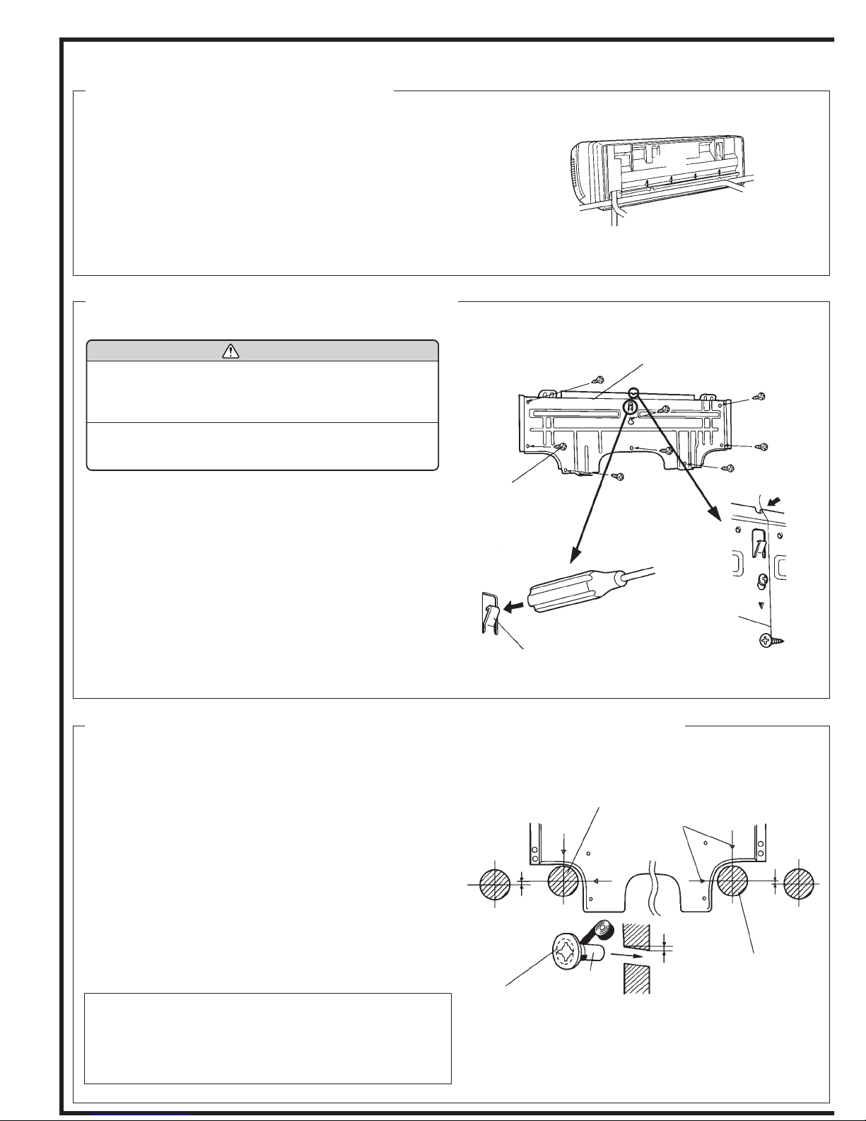
INSTALLING THE WALL HOOK BRACKET
CAUTION
1 Install the wall hook bracket so that it is correctly
positioned horizontally and vertically. If the wall
hook bracket is tilted, water will drip to the floor.
2 Install the wall hook bracket so that it is strong
enough to withstand the weigtht of an adult.
(1) Before fastening the wall hook bracket to the wall with the screws,
level it by tapping the hook at the center of bracket to the wall with
the handle of a screwdriver.
(2) Fasten the wall hook bracket to the wall with 6 or more screws through
the holes near the outer edge of the bracket.
(3) Check that there is no rattle at the wall hook bracket.
Fig. 4
2 Right outlet
Fig. 5
Tapping screw
(big)
Ta p
(Rear)
1 Rear outlet
3 Bottom outlet
Wall hook bracket
(Handle of screwdriver)
5 Left outlet
4 Left rear outlet
Center notch
Hook
Wall hook
bracket
String
Hook
CUTTING THE HOLE IN THE WALL FOR THE CONNECTING PIPING
(1) Cut a 3-2/16” (80 mm) diameter hole in the wall at the position shown
in (Fig. 6).
(2) When cutting the wall hole at the inside of the wall hook bracket, cut
the ø80 mm hole within the range of the left and right center marks.
When cutting the wall hole at the outside of the wall hook bracket,
cut the hole at least 3/8” (10 mm) below the center line.
(3) Cut the hole so that the outside end is lower 3/16” to 3/8” (5 to 10
mm) than the inside end.
(4) Always align the center of the wall hole. If misaligned, water leakage
will occur.
(5) Cut the wall pipe to match the wall thickness, stick it into the acces-
sory wall cap-B, fasten the cap with vinyl tape, and stick the pipe
through the hole. (The connection pipe is supplied in the installation
set.) (Fig. 6)
(6) For Left piping and right piping, cut the hole a little lower so that
drain water will flow freely. (Fig. 6)
NOTE:
• Always align the center of the wall hole. If misaligned, water leakage
will occur.
• If the wall hole pipe is not used, the cord interconnecting the indoor
and outdoor units may touch metal and cause electric leakage.
Fig. 6
3-2/16” (80 mm) dia. hole
Center mark
Lower
3/8”
(10 mm) or over
Fasten with
vinyl tape
(Wall pipe)
Wall cap-B
(Inside) Wall (Outside)
3/16” to 3/8”
(5 to 10 mm) low
3-2/16” (80 mm) dia.
hole (Rights side hole
only. 2-9/16” (65 mm)
diameter hole is also
possible.)
Counter weight
Lower
3/8”
(10 mm) or over
Page 4
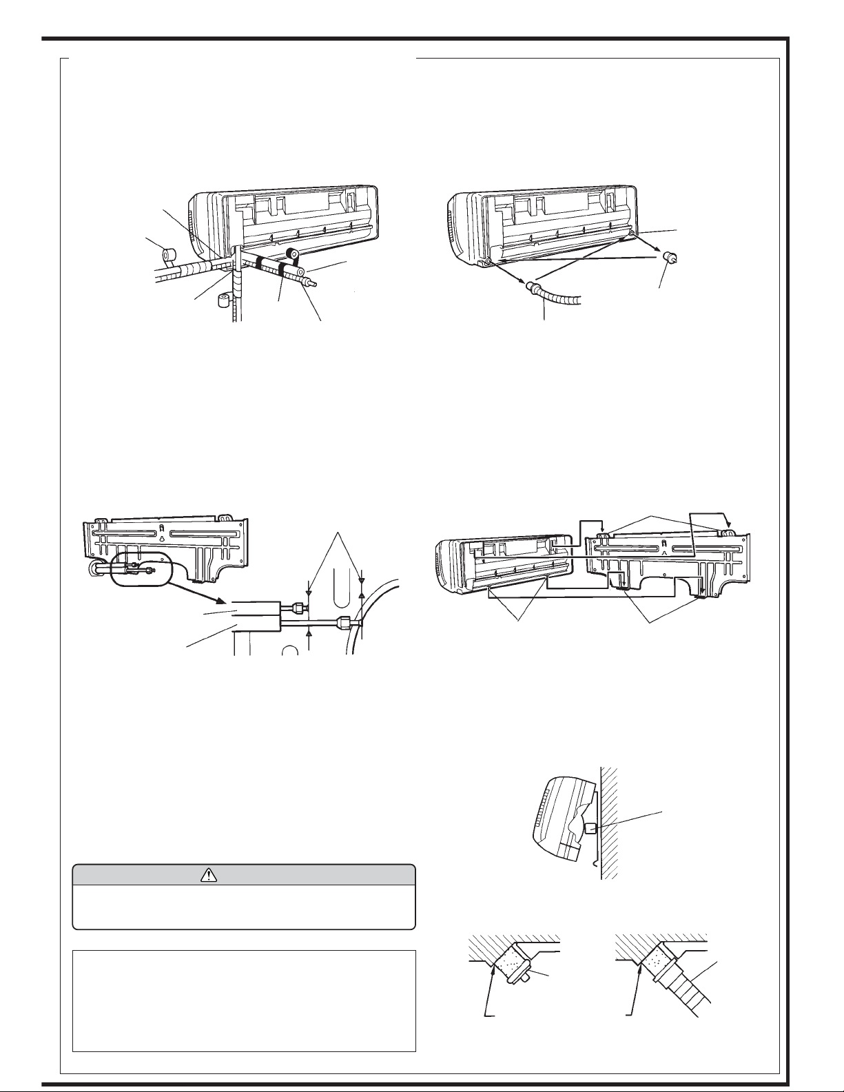
FORMING THE DRAIN HOSE AND PIPE
[Rear piping, Right piping, Bottom piping]
• Install the indoor unit piping in the direction of the wall hole and bind the drain hose and pipe together with vinyl tape. (Fig. 7)
• Install the piping so that the drain hose is at the bottom.
• Wrap the pipes of the indoor unit that are visible from the outside with decorative tape.
Fig. 7
Cut off the piping
outlet cutting
groove with a
hacksaw, etc.
Decorative tape
Pipe (top)
Right piping
Notch the thin part
of under cover A.
Bind with
vinyl tape
Bottom piping
Rear piping
Indoor unit drain
hose (bottom)
Indoor unit drain hose
Drain cap
Remove the drain cap by
pulling at the projection at the
end of the cap with pliers, etc.
[For Left rear piping, Left piping]
Interchanging the drain cap and the drain hose.
• For left piping and left rear piping, align the marks on the wall hook bracket and shape the connection pipe.
• After passing the indoor piping and drain hose through the wall hole, hang the indoor unit on the hooks at the top and bottom of the wall
hook bracket.
For left outlet
piping, cut off
the piping outlet
cutting groove
with a hacksaw.
Fig. 8
Align the marks.
Connection pipe
(1/4” (6.35 mm) dia.)
Connection pipe
(3/8” (9.52 mm) dia. or
1/2” (12.7 mm) dia.)
[Installing the indoor unit]
• Hang the indoor unit from the hooks at the top of the wall hook
bracket.
• Insert the spacer, etc. between the indoor unit and the wall hook
bracket and separate the bottom of the indoor unit from the wall.
CAUTION
After removing the drain hose, don’t forget to install
the drain cap.
Top hooks
Indoor unit
Bottom hooks(Fitting)
After hooking the indoor unit to the top hook, hook the fittings
of the indoor unit to the two bottom hooks while lowering the
unit and pushing it against the wall.
Fig. 9
Indoor unit
Wall hook bracket
Fig. 10
Wall hook
bracket
Spacer
NOTE:
• To prevent breaking of the pipe, avoid sharp bends. Bend the pipe
with a radius of curvature of 4” (100 mm) or more.
• If the pipe is bent repeatedly at the same place, it will break.
• Do not remove the flare nut from the indoor unit pipe until imme-
diately before connecting the connection pipe.
Drain cap
Insert the drain cap and drain
hose until it butts against the
drain port.
Indoor unit
drain hose
Page 5
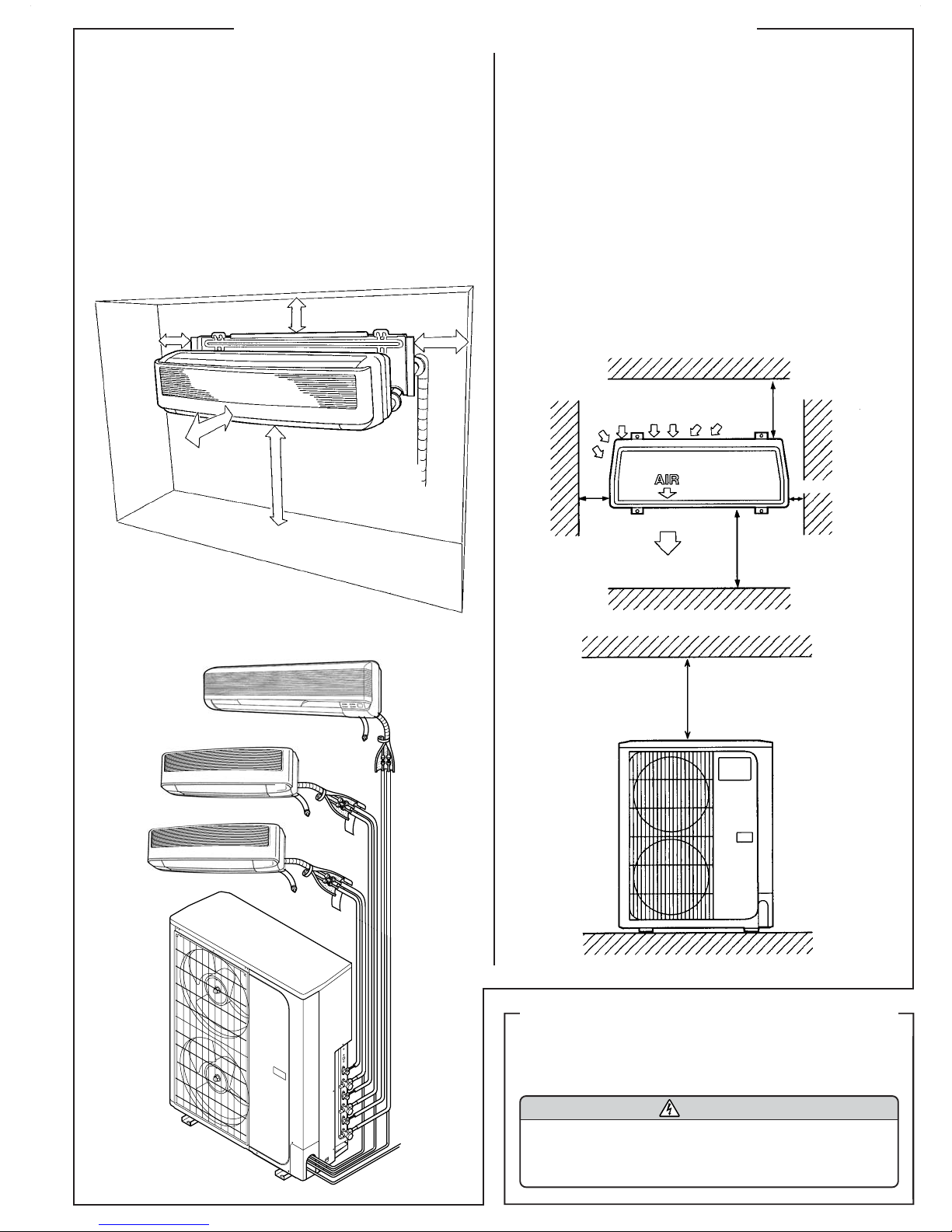
SELECTING THE MOUNTING POSITION
1. INDOOR UNIT
(1) Install the indoor unit level on a strong wall which is not subject
to vibration.
(2) The inlet and outlet ports should not be obstructed : the air should
be able to blow all over the room.
(3) Do not install the unit where it will be exposed to direct sun-
light.
(4) Install the unit where connection to the outdoor unit is easy.
(5) Install the unit where the drain pipe can be easily installed.
(6) Take servicing, etc. into consideration and leave the spaces
shown in (Fig. 1). Also install the unit where the filter can be
removed.
Fig. 1
Right side
5 cm
or over
Left side
5 cm
or over
150 cm
or over
6 cm or over
150 to 200 cm
2. OUTDOOR UNIT
(1) If possible, do not install the unit where it will exposed to direct
sunlight. (If necessary, install a blind that does not interfere with
the air flow.)
(2) Install the outdoor unit in a place where it will be free from be-
ing dirty or getting wet by rain as much as possible.
(3) Install the unit when connection to the indoor unit is easy.
(4) Do not place animals and plants in the path of the warm air.
(5) Take the air conditioner weight into account and select a place
where noise and vibration are small.
(6) Select a place so that the warm air and noise from the air condi-
tioner do not disturb neighbors.
(7) Provide the space shown in Fig. 2 so that the air flow is not
blocked. Also for efficient operation, leave open three of the four
directions front, rear, and both sides.
(8) Install the unit near the special branch circuit.
Fig. 2
30 cm
or over
1 cm or over
10 cm
or over
Fig. 3
UNIT B (Large)
UNIT A2 (Small)
UNIT A1 (Small)
60 cm
or over
60 cm or over
ELECTRICAL REQUIREMENT
Always make the air conditioner power supply a special branch circuit and provide a special switch and receptacle. Do not extend the
power cord.
CAUTION
MINIMUM CIRCUIT AMPACITY 25A
MAXIMUM OVERCURRENT PROTECTION 30A
(TIME DELAY FUSE OR HACR TYPE CIRCUIT BREAKER)
Page 6

INDOOR UNIT INSTALLATION (UNIT B)
INDOOR UNIT PIPING DIRECTION
The piping can be connected in the five directions indicated by 1, 2,
3, 4, and 5 in Fig. 11. When the piping is connected in direction 2
or 5, cut a notch along the piping groove in the side of the under
cover with a hacksaw. When connecting the piping in direction 3,
cut a notch in the thin wall at the front bottom of the under cover.
Fig. 11
(Rear)
5 Left
outlet
2 Right outlet
3 Bottom outlet
1 Rear outlet
4 Left rear
outlet
INSTALLING THE WALL HOOK BRACKET
Removing the wall hook bracket
Remove the wall hook bracket in the following order:
1 Remove one side of under cover B by pulling it forward
(arrow direction in Fig. 12).
2 Remove the other side of under cover B by pulling it for-
ward (arrow direction in Fig. 12).
3 Remove the tapping screw installed to under cover A. (Fig. 13)
4 While pulling the right side of under cover A forward (re-
leasing the inside stopper), slide under cover A to the left
and unhook the two inside hooks. (Fig. 13)
5 Next, remove under cover A by pulling the left side forward
(arrow direction in Fig. 13).
6 Remove the four tapping screws holding the wall hook
bracket. (Fig. 14)
Fig. 12
(1) Install the wall hook bracket so that it is correctly positioned hori-
zontally and vertically. If the wall hook bracket is tilted, water
will drip to the floor.
(2) As the weight of the indoor unit is 37 to 44 Ibs (17 to 20 kg), it
should be installed after properly examining the place where it
is intended to be installed. If the place is not strong enough, a
plank or girder should be used to make the place sufficiently
strong so that the wall can support the weight.
[Installation directly to a wall]
Before fastening the wall hook bracket to the wall with the screws,
level it by tapping the hook at the center of bracket to the wall with the
handle of a screwdriver.
• Fasten the wall hook bracket to the wall with 6 or more screws and
anchor bolts through the holes near the outer edge of the bracket.
• Do not install the wall hook bracket at only one place or at an angle.
For a concrete wall, embed anchor bolts 3/8” (10 mm dia.) into the
wall at the hook bracket holes 15/32” × 23/32” dia (12 × 18 mm dia.).
Allow the anchor bolts to stick out at least 23/32” (18 mm) from the
wall. (Fig. 15) Install the unit to the anchor bolts with nuts through
the wall hook bracket. Use 2 bolts for concrete wall and 4 bolts for
blister concrete wall.
• Finally tighten the bolts and wood screws after confirming, using
the level indicator, that the clamp is horizontal.
CAUTION
Install the wall hook bracket horizontally and perpendicularly. If the wall hook bracket is tilted, water will
drip to the floor.
Fig. 15
9-15/32” (241)
Piping
inlet
23-17/32”
(57)
2-1/4”
(598)
Wall hook bracket
24-1/2” (622) 24-23/32” (628)
”
(216)
(366)
18-15/32”
14-13/32
2-5/32”
(55)
84-ø1/4” (6) hole
for tapping screw
18-23/32” (466) 18-19/32” (472)
(133)
(219)
5-1/4”
8-19/32”
20-ø15/32”×23/32”
(12×18) hole for bolt
9-5/8”
(244)
Bolt
(373)
14-11/16”
2-5/32”
(55)
(604)
23-25/32”
(57)
2-1/4”
Piping inlet
31/32” (24)
1-13/32” (36)
3” (76)
5-5/32”
(131)
7-5/16” (186)
9-1/2”
(241)
12-13/32”
(315)
12-19/32” (320)
1
Under cover B
Fig. 13
5
Hook
Under cover A
Fig. 14
Wall hook bracket
Stopper
4
Tapping screw
6
2
3
Tapping screw
Fig. 16
23/32” (18 mm) max.
Wall hook bracket
Tapping
screw (big)
Tapped
(Handle of screwdriver)
Hook
Wall
Anchor bolt
Center notch
Hook
Wall hook
bracket
String
Counter
weight
Page 7

CUTTING THE HOLE IN THE WALL
FOR THE CONNECTING PIPING
WARNING
If the wall pipe is not used, the cord interconnecting
the indoor and outdoor units may touch metal and
cause electric leakage.
(1) Cut a 3-15/16” (100 mm) diameter hole in the wall at the position
shown in Fig. 17.
(2) When cutting the wall hole at the inside of the installation frame,
cut the hole to a point of intersection of center marks.
When cutting the wall hole at the outside of the installation frame,
cut the hole at least 3/8” (10 mm) below this center point.
(3) Cut the hole so that the outside end is lower 3/16” to 3/8” (5 to 10
mm) than the inside end.
(4) Always align the center of the wall hole. If misaligned, water
leakage will occur.
(5) Cut the wall pipe to match the wall thickness, stick it into the
wall cap, fasten the cap with vinyl tape, and stick the pipe through
the hole. (The connection pipe is supplied in the installation set.)
(Fig. 17)
Fig. 17
Center mark
Fig. 18
Cut off the piping
outlet cutting
groove with a
hacksaw, etc.
Decorative
tape
Pipe (top)
Right
piping
Notch the thin
part of under
cover A.
• Perform “ELECTRICAL WIRING” before performing this piping.
• Wrap the pipes of the indoor unit that are visible from the outside
with decorative tape.
• After passing the indoor piping and drain hose through the wall
hole, hang the indoor unit on the hooks at the top of the wall hook
bracket.
Bottom piping
Bind with vinyl tape
Rear piping
Indoor unit drain hose (bottom)
Fig. 19
Top hooks
Lower
3/8” (10 mm)
or over
(6) For 5 left piping and 2 right piping, cut the hole a little lower so
that drain water will flow freely (Fig. 17).
Wall cap
Fasten with
vinyl tape
(Wall pipe)
(Inside) Wall (Outside)
3-15/16”
(100 mm) dia. hole
3/16” to 3/8”
(5 to 10 mm) less
Lower
3/8” (10 mm)
or over
FORMING THE DRAIN HOSE AND PIPE
CAUTION
1 Do not remove the flare nut from the indoor unit
pipe until immediately before connecting the connection pipe.
2 To prevent breaking of the pipe, avoid sharp
bends. Bend the pipe with a radius of curvature
of 4˝ (100 mm) or more.
Indoor unit
Wall hook
bracket
[For 4 Left rear piping, 5 Left piping]
• Left piping and left rear piping can be easily installed by removing
the pipe bracket.
Removing the pipe bracket
Remove the three tapping screws holding the pipe bracket as
shown below.
Fig. 20
3 If the pipe is bent repeatedly at the same place, it
will break.
[1 Rear piping, 2 Right piping, 3 Bottom piping]
• Install the indoor unit piping in the direction of the wall hole and
bind the drain hose and pipe together with vinyl tape. (Fig. 18)
• Install the piping so that the drain hose is at the bottom.
Page 8

OUTDOOR UNIT INSTALLATION
• For left piping and left rear piping, preset the end of the pipe to the
dimensions shown in Fig. 21 from the mark on the wall hook bracket
and form the connection pipe.
• Bend the connection piping at a bend radius of at least 4“ (100
mm) and position it no more than 2“ (50 mm) from the wall.
Fig. 21
Bend (R100) with
a pipe bender
• When extending the drain hose at the indoor unit, install the
accessory drain insulation.
Connection pipe
1/4” (6.35 mm dia.)
14-31/32
About 17-5/16
Connection pipe
1/2” (12.7 mm dia.)
About
” (380 mm)
” (440 mm)
Fig. 22
Drain insulation
Indoor unit drain hose
Drain hose
• Place the indoor unit drain hose behind the piping.
Vinyl tape
WARNING
1 Install the unit where it will not be tilted by more
than 5°.
2 When installing the outdoor unit where it may
exposed to strong wind, fasten it securely.
• Set the unit on a strong stand, such as one made of concrete
blocks to minimize shock and vibration.
• Do not set the unit directly on the ground because it will cause
trouble.
OUTDOOR UNIT PROCESSING
When the outdoor unit will be exposed to strong wind, fasten it
with bolts at the places indicated by the arrows (Fig. 25).
Fig. 25
Bottom
15-3/4” (400 mm)
25-19/32” (650 mm)
4-ø12 hole (Anchor bolt M10)
[Installing the indoor unit]
• Piping work can be made easier by laying out, shaping, and temporarily fastening the connection pipe, drain hose, and connection cord as shown in Fig. 23 beforehand.
Fig. 23 (Left piping)
Indoor unit
Drain hose
Connection cord
Pipe
Connect the piping
INSTALLING THE INDOOR UNIT
After connecting the piping, fasten the bottom of the indoor unit and
the wall hook bracket with the tapping screws.
Fig.24
Indoor unit
Wall hook bracket
Pipe bracket
Tapping screw
Page 9

CONNECTING THE PIPING
CAUTION
The maximum lengths of product are shown in Table
1. If the units are further apart than this, correct operation can not be guaranteed.
1. LIMITATION OF REFRIGERANT PIPING
LENGTH
Table 3
Total max length (A1+A2)
Total max length (B)
Max length for each indoor unit
(A1 or A2 or B)
Max height difference (H)
Fig. 26
OUTDOOR UNIT
98 ft (30 m)
49 ft (15 m)
49 ft (15 m)
26 ft (8 m)
INDOOR UNIT
4. CONNECTION
(1) Install the outdoor unit wall cap (supplied with the optional instal-
lation set or procured at the site) to the wall hole pipe.
(2) Connect the outdoor unit and indoor unit piping.
(3) After matching the center of the flare surface and tightening the
nut hand tight, tighten the nut to the specified tightening torque
with a torque wrench. (Tighten the flare nut of the outdoor unit 3-
way valve after air purging.)
Fig. 29
Torque wrench
Indoor unit pipe
Flare nut
6.35 mm (1/4”) dia.
12.7 mm (1/2”) dia.
Tighten with two wrenches.
Wrench (fixed)
Flare nut
Connection pipe
Table 4 Flare Nut Tightening Torque
Tightening torque
15.7 to 17.6 N • m
(160 to 180 kgf • cm)
49.0 to 53.9 N • m
(500 to 550 kgf • cm)
Tightening torque standard
(using a 20 cm wrench)
Wirst strength
Arm strength
To prevent Gas
leakage, coat the
flare surface with
refrigerator oil.
2. FLARING
(1) Cut the connection pipe to the necessary length with a pipe cutter.
(2) Hold the pipe downward so that cuttings will not enter the pipe
and remove the burrs.
(3) Insert the flare nut onto the pipe and flare the pipe with a flaring
tool.
Fig. 27
Check if [L] is flared uniformly and is not cracked or
scratched.
L dimension Thin pipe (6.35 mm dia.) 1.4 to 1.7 mm
Thick pipe (12.7mm dia.) 1.9 to 2.2 mm
L
3. BENDING PIPES
The pipes are shaped by your hands. Be careful not to collapse them.
Fig. 28
Do not remove the cap from the connection pipe before connecting
the pipe.
Fig. 30
OUTDOOR UNIT
Connection pipe
Flare nut
Do not bend the pipes in an angle more than 90°.
When pipes are repeatedly bent or stretched, the material will
harden, making it difficult to bend or stretch them any more. Do
not bend or stretch the pipes more than three times.
Torque wrench
Page 10

ELECTRICAL WIRING
HOW TO CONNECT WIRING TO THE TERMINALS
A. For solid core wiring (or F-cable)
(1) Cut the wire end with a wire cutter or wire-cutting pliers, then strip
the insulation to about 15/16” (25 mm) of expose the solid wire.
(2) Using a screwdriver, remove the terminal screw(s) on the terminal
board.
(3) Using pliers, bend the solid wire to form a loop suitable for the
terminal screw.
(4) Shape the loop wire properly, place it on the terminal board and
tighten securely with the terminal screw using a screwdriver.
B. For strand wiring
(1) Cut the wire end with a wire cutter or wire-cutting pliers, then strip
the insulation to about 3/8” (10 mm) to expose the strand wiring.
(2) Using a screwdriver, remove the terminal screw(s) on the terminal
board.
(3) Using a round terminal fastener or pliers, securely clamp a round
terminal to each stripped wire end.
(4) Position the round terminal wire, and replace and tighten the ter-
minal screw using a screwdriver.
Fig. 32
Solid wire
Strandwire
Loop
Round
terminal
Fig. 33
TERMINAL
TERMINAL
TERMINAL
WIRING SYSTEM DIAGRAM
INDOOR UNIT
INDOOR UNIT A1
1
2
3
G
1
2
3
G
1
2
3
G
DISCONNECT SWITCH
(FIELD SUPPLY)
INDOOR UNIT A2
DISCONNECT SWITCH
(FIELD SUPPLY)
INDOOR UNIT B
DISCONNECT SWITCH
(FIELD SUPPLY)
14AWG
(Inter-unit)
Power lines
230/208 V
230/208 V
230/208 V
Grounding
line
230/208 V
230/208 V
230/208 V
Grounding
line
230/208 V
230/208 V
230/208 V
Grounding
line
OUTDOOR UNIT
TERMINAL
1
2
3
G
4
5
6
G
7
FUSE
8
9
G
0
A
N
G
Power supply line
Single-phase, 230/208 V,10AWG
Insulation
Strip 15/16” (25 mm)
Wire
Screw with
special washer
Round
terminal
terminal
board
Strip 3/8” (10 mm)
Screw with
special washer
Round
terminal
Wire
WARNING
1 Before starting work, check that power is not be-
ing supplied to indoor units and the outdoor unit.
2 Match the terminal block numbers and connection
cord colors with those of the indoor unit side. Erroneous wiring may cause burning of the electric
parts.
3 Connect the connection cords firmly to the termi-
nal block. Imperfect installation may cause a fire.
4 Always fasten the outside covering of the connec-
tion cord with cord clamps. (If the insulator is
clamped, electric leakage may occur.)
5 Always connect the ground wire.
Page 11

OUTDOOR UNIT SIDE
(1) Remove the outdoor unit cabinet A and cabinet D.
Fig. 34
* After removing the screws, remove
cabinet A by pushing it down
(4) Temporarily mount the conduit tubes on the conduit plate.
(5) Properly connect both the power supply and inter-unit wire har-
ness to the corresponding terminals on the terminal board.
Refer to the wiring system diagram in Fig. 33.
(6) Ground the unit in accordance with local codes.
(7) Be sure to size each wire allowing several inches longer than the
required length for wiring.
(8) Use lock nuts to secure the conduit tubes.
Cabinet A
mounting direction
Cabinet A
mounting direction
Cabinet D
* Use the accessory screws at these points only
(2) Open the connection knockout holes of the desired direction with
nippers, etc. After opening the knockout holes, install the accessory edge cover to protect the opened places.
Fig. 35
Knockout hole
Cabinet D
Power supply line
Fig. 36
Lock Nut
Conduit plate
/
/
/
/
Inter-Unit
Edge cover
Pipe mounting hole
line
(3) Connect the piping and power supply cord from the mounting
holes.
Inter-Unit line
Power supply line
Page 12

INDOOR UNIT SIDE
UNIT A1 and A2
(1) Remove the intake grill (Fig. 50).
(2) Remove the front panel (Fig. 51 and 52).
(3) Remove the screw 1 , and remove Cover-C.
(4) Remove the screw 2 , and remove Cover-D.
(5) Remove the screw 3 , and remove the Conduit holder.
(6) Fasten the Inter-unit wire harness to the Conduit holder using the
Lock nut.
(7) Install the Conduit holder to its original state with the screw 3.
Fig. 37
Cover-D
Cover-C
Screw
Screw
(8) Install Cover-D to its original state with the screw 2.
(9) Install Cover-C to its original state with the screw 1.
Fig. 38
Inter-unit wire harness
UNIT B
(1) Remove the intake grill (Fig. 54).
(2) Remove the front panel (Fig. 55 and 56).
(3) Remove the control box cover (Fig. 39).
Removing the control box cover
Fig. 39
(4) Process the end of the connection cords to the dimension shown
in Fig. 40 and bend the end of each wire as shown.
(5) Connect the end of the connection cord fully into the terminal
board and fasten with the screw.
Fig. 40
Terminal board
Screw
Cover-C
Lock nut
Conduit
holder
Inter-unit wire harness
Screw
Cover-D
REMOTE CONTROL UNIT CODE SWITCHING
(UNIT B model only)
Fig. 41
JM1
JM2
JM3
AUTORESTART
REMOCON 2
REMOCON 1
Indoor unit
Printed circuit board
Remote control unit
ABCD
Remote control unit
signal selector switch
ABCD
Match the remote control unit signal selector switch selection and
printed circuit board setting according to Table 5.
If these are not matched, the remote control unit cannot be
operated for the air conditioner.
ACL
After setting the remote control unit signal selector switch, press the
ACL button.
Earth screw
Lock nut
Plug
Connection cord
(Inter-Unit line)
Jumper wire
JM 2 JM 3
Connect Connect
Connect Disconnect
Disconnect Connect
Disconnect Disconnect
123456
Table 5
25 mm
20 mm
Remote control unit
signal selector switch
A (Primary setting)
B
C
D
Page 13

VACUUM PROCESS POWER
CAUTION
1 When moving and installing the room air condi-
tioner, do not mix gas other than the specified
refrigerant (R22) inside the refrigerant cycle.
2 Charging of additional refrigerant (R22) accord-
ing to the piping length is unnecessary.
3 After connecting the piping, check the joints for
gas leakage with gas leak detector.
(1) Remove the cap, and connect the gauge manifold and the vacuum
pump to the charging port by the service hoses.
(2) Vacuum the indoor unit and the connecting pipes until the pres-
sure in them lowers to below 1.5 mmHg.
(3) Disconnect the service hoses and fit the cap the charging port
(Tightening torque : 8.8 to 11.8 N • m (90 to 120 kgf • cm)).
(4) Remove the blank caps, and fully open the spindles of the 2-way
and 3-way valves with a hexagon wrench (torque: 4.9 to 6.9 N •
m (50 to 70 kgf • cm)).
(5) Tighten the blank caps of the 2-way valve and 3-way valve to the
specified torque:
2-way valves torque: 19.6 to 24.5 N • m (200 to 250 kgf • cm)
3-way valves torque: 31.4 to 37.2 N • m (320 to 380 kgf • cm)
Fig. 31
Connecting pipe
WARNING
1 The rated voltage of this product is 230-208 V A.C.
60 Hz.
2 Before turning on the verify that the voltage is
within the 187 V to 253 V range.
3 Always use a special branch circuit and install a
special receptacle to supply power to the room
air conditioner.
4 Use a circuit breaker and receptacle matched to
the capacity of the room air conditioner.
When connecting the power supply to the outdoor unit, always install a circuit breaker between
the outdoor unit and the power supply. Use the
circuit breaker has an isolation distance of at least
3 mm between the contacts of each pole.
5 Perform wiring work in accordance with stand-
ards so that the room air conditioner can be operated safely and positively.
6 Install a leakage circuit breaker in accordance with
the related laws and regulations and electric company standards.
OUTDOOR UNIT
Service hose with
valve core
Gauge manifold
2-way valve
3-way valve
Service hose
Charging port
Cap
OUTDOOR UNIT
3-way valve
Blank cap
CAUTION
1 The power source capacity must be the sum of
the room air conditioner current and the current
of other electrical appliances. When the current
contracted capacity is insufficient, change the
contracted capacity.
2 When the voltage is low and the air conditioner
is difficult to start, contact the power company
the voltage raised.
Connection pipe
Vacuum pump
Page 14

FINISHING
(1) Heat insulate the connections between pipes.
• For rear, right, and bottom piping, butt the connection piping insulation material against the indoor unit piping and fasten it with seal
A (UNIT B only) and vinyl tape so there is no gap.
• For left and left bottom piping wrap the piping with cloth tape within
the range that encompasses the piping housing section at the rear
of the indoor unit.
(2) Push the bottom of the indoor unit against the wall and hook the
two pawls at the bottom of the indoor unit to the mounting plate
hooks. At this time, check the following:
• Are the top and bottom hooks seated positively? Check by moving
the indoor unit forward, backward, left and right.
• Is the indoor unit installed level and perpendicular?
• For left rear piping, is the drain hose at the bottom of the wall hole
pipe?
(3) Temporarily fasten the connection cable along the connection pip-
ing with vinyl tape and wrap decorative tape around the part that is
visible from the body. For right, bottom, and left piping, securely
wrap the part coming from the body with decorative tape so that
the piping does not swell. (Overlap wrapping of outdoor parts about
1/3 of the width of the tape from the bottom of the piping so that
water will not enter.)
(4) Fasten the connection pipe to the outside wall with a saddle, etc.
(5) Fill the gap between the outside wall pipe hole and the pipe with
sealer so that rain water and wind cannot blow in.
(6) Fasten the drain hose to the outside wall, etc.
UNIT B
Installing the under covers
(1) Installing under cover A (Fig. 42)
1 Hook the two pipe bracket hooks to the two holes in the back
of under cover A.
2 While pulling the left side of under cover A forward about 1
cm (at this time, hold hook 1 so that it does not come
unhooked), slide under cover A to the right and hook the hook.
3 Push the left side of under cover A in the arrow direction and
attach the two side hooks to the base.
4 Install under cover A to the pipe bracket with the tapping screw.
Fig. 42
Base
Side
hook
(2) Installing under cover B (Fig. 43)
5 Push the left side of under cover B in the arrow direction and
attach the two hooks to under cover A.
6 Push the right side of under cover B in the arrow direction and
attach the two side hooks to the base.
Pipe bracket
3
Under cover A
Hook
4
Tapping
2
1
Hole
Stopper
screw
Fig. 44
Connection pipe (heat insulation)
Butt connection pipe (heat insulation) against the
indoor unit pipe (heat insulation) and wrap with
seal A so that there is no gap.
Fig. 45
Pipe
Drain hose
Fig. 46
Connection cord
Pipe
Fig. 47
For connection from the left rear
Connection pipe
Drain hose
Fig. 48
Check the following:
GOOD
Drain hose
Saddle
Fig. 49
Indoor unit pipe (heat insulation)
Vinyl tape
Seal A
Wrap with cloth tape
Cloth tape
Left piping
Drain hose
Wall pipe
Connection cord
(View from indoors)
BAD BAD BAD
Lifted up
Wave
End in water
Fig. 43
Under cover A
5
Under cover B
Base
6
Side hook
Pipe
(Saddle)
Wall
(Outside wall cap)
(Sealer putty)
(Outdoors)
Page 15

FRONT PANEL REMOVAL
CAUTION
Install the front panel and intake grille securely. If installation is imperfect, the front panel or intake grille
may fall off and cause injury.
UNIT A1 and A2
1. INTAKE GRILLE REMOVAL
(1) Place your fingers at both lower ends of the grille panel, and lift
forward; if the grille seems to catch partway through its movement,
continue lifting upward to remove.
(2) Pull past the intermediate catch and open the intake grille wide so
that it becomes horizontal.
Fig. 50
2. UNLOCK THE INTAKE GRILLE
Hold the intake grille with one hand and pull the knobs on the right and
the left all the way to unlock the intake grille.
Fig. 51
Intake grille
Mounting shaft
UNIT B
1. INTAKE GRILLE REMOVAL
(1) Open the intake grille.
(2) Open the intake grille and lift the intake grille upward until the hook
at the top of the intake grille is unhooked.
Fig. 54
(Hook)
Intake
grille
Lift
Open
Lift
Open
Lift
2. FRONT PANEL REMOVAL
(1) Remove the four tapping screws.
(2) Remove the front panel by lifting the bottom of the front panel
upward.
Fig. 55
(Hook)
Front
panel
Knob
Raise the horizontal intake grille to remove it.
(1) Remove the two screws.
(2) Unhook the tab at the center of the front panel.
(3) Remove the front panel by lifting it in the arrow direction.
Fig. 52
Tab
3. FRONT PANEL INSTALLATION
(1) Engage the body tabs by pressing on the top of the unit at the three
points indicated by the arrows until the tabs make a sound.
(2) Engage the tab at the center of the front panel and fasten the front
panel with the two screws.
Fig. 53
Tapping screw
3. FRONT PANEL INSTALLATION
(1) Hook the top hole of the front panel to the hook of the base.
(2) Fasten the front panel with the screw.
Fig. 56
(Top hook)
Front panel
(Top hole)
Be sure that the top hole of the front panel is attached securely to
the hook of the base.
Tab
Page 16

TEST RUNNING REMOTE CONTROL UNIT HOLDER
• Perform test operation and check items 1 and 2 below.
• For the operation method, refer to the operating manual.
• The outdoor unit may not run, depending on the room tempera-
ture. In this case, press the TEST RUN button of the remote control
unit while the room air conditioner is running.
Fig. 57
UNIT A1, A2 UNIT B
Remote control
unit (rear)
TEST RUN button
TIME ADJUST
button
START
STOP
ABCD
Operation can be checked by the lighting and flashing of the display
section OPERATION and TIMER lamps.
Perform judgment in accordance with the following.
• Test run
When the air conditioner is run by pressing the remote control
unit test run button, the OPERATION and TIMER lights flash
slowly at the same time.
• Error
The OPERATION and TIMER lights operate as follows (Table 6)
according to the error contents.
Table 6
Error display Error contents
OPERATION
light
TIMER
light
OPERATION
light
TIMER
light
0.5 sec
ON
OFF
0.1 sec
ON
OFF
0.1 sec
0.5 sec
ON
OFF
0.1 sec
ON
OFF
0.1 sec
5 sec
5 sec
0.5 sec
Two quick
flashes
repeated
0.1 sec ON/OFF
repeated
0.5 sec
Three quick
flashes
repeated
0.1 sec ON/OFF
repeated
Room temperature
thermistor abnormal
temperature
detected
Piping thermistor
abnormal
temperature
detected
INSTALLATION
CAUTION
1 Check that the indoor unit correctly receives the
signal from the remote control unit, then install
the remote control unit holder.
2 Select the remote control unit holder selection
site by paying careful attention to the following:
Avoid places in direct sunlight.
Select a place that will not be affected by the heat from
a stove, etc.
Install the remote control unit holder to a wall or pillar with the tapping screws.
Fig. 58
UNIT A1, A2
Remote control unit
holder fixing
Remote control
unit holder
Tapping
screw
(small)
Fig. 59
UNIT B
For use as Hand Control
Insert Slide up
Screws
1 Mount the Holder. 2 Set the Remote
Control Unit.
For use as Wall Attachment
Insert
1 Push
Remote
control unit
Remote control
1 Set
unit mounting
3 To remove the Remote
Control Unit
CHECK ITEMS
(1) INDOOR UNIT
(1) Is operation of each button on the remote control unit normal?
(2) Does each light function normally?
(3) Do air flow direction louvers operate normally?
(4) Is the drain normal?
(5) Is there any abnormal noise and vibration during operation?
(2) OUTDOOR UNIT
(1) Is there any abnormal noise and vibration during operation?
(2) Will noise, wind, or drain water from the unit disturb the
neighbors?
(3) Is there any gas leakage?
• Do not operate the air conditioner in the test run mode for a long
time.
• For the operation method, refer to the operating manual and perform operation check.
Screws
1 Mount the Holder. 2 Set the Remote
Control Unit.
Screw
Slide
3 Attach the unit to the
holder as shown.
PART. NO 9369651014
 Loading...