Mastech MS6530T Operation Manual

Page 1
MS6530T
Infrared Thermometer
Operations Manual
Page 2
CONTENTS CONTENTS
1.Safety information ..........................1
2.Warning ..........................................1
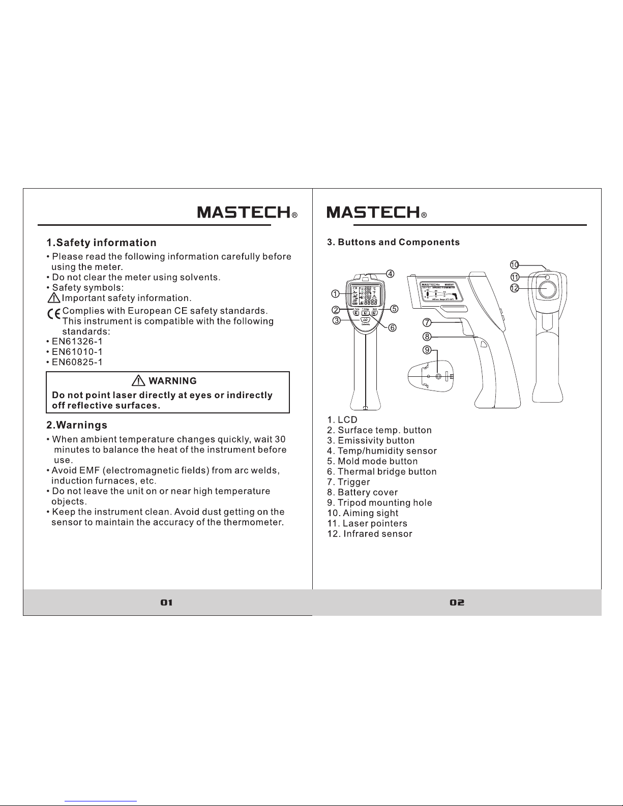
3. Buttons and Components..... ............2
5. IRT Technology...............................4
6. Operating Instructions ...................4
6.1 Preparation...............................................4
6.2 Turning On The Instrument........................4
6.3 Selecting Emissivity...................................4
6.4 Selecting Temperature Units......................5
6.5 Surface Temperature Measurements .........5
6.6 Thermal Bridge Mode ................................5
6.7 Mold Warning Mode.......................................6
7. Error Messages ...............................8
7.1 Temperatur e Sensor
Not Acclimated...................................... 8
7.2 Ambient Temperature Outside
Operating Range.........................................8
7.3 Surface Temperature outside
Measureable Range ....................................9
7.4 Internal Erro r........................................10
8. Distance to Spot Ratio (D:S)...........10
9. Emissivity......................................11
10. Thermal Bridg..............................12
11. Changing the battery....................12
12. Specifications..............................13
Page 3
Page 4
Page 5
Page 6
07 08
7. Error Messages
7.1 Temp erature Sensor Not Acclimated
1.The instrume nt has be en exposed to severe temperature va riati ons and needs time to accli matiz e to the current env ironm ent.
2.The instrume nt will s how the above symbols.
3.Keep the instr ument i n the current environme nt for approx. 10-30 mi nutes s o it has enough time to adapt to the environme nt.
7.2 Ambient Temper ature O utside Operating Rang e
3.The display wi ll show the current surface temp eratu re of the object with in the me asurement spot, ambie nt temperature, r elati ve humidity and dew point temperature. Af ter rel easing the trigger the di splay will hold the curr ent mea surement.
4.The LED above th e display will indicate the poss ible presence of mold .
• Green: High temp eratu re differenc e. No ris k of mold detected.
• Yellow: Med ium tem perature differen ce.Possible mold risk presen t.Che ck again at a later time to ver ify.
• Red: Low tempera ture di fference.H igh Hig h risk of mold detected. The display will flash t he appr opriate measurement th at may be t he cause.
• After approx. 25s f rom rel easing the trigger, the instrument wil l autom atically turn itself off. Note: Reduce the h umidity or increase the ambien t temperature if h igh ris k of mold is detected.The instrument can not det ect mold spores.The ins trume nt only give s an indi cation that mold formation is po ssibl e at the given locat ion.
Page 7
09 10
7.4 Internal Err or
1.The instrume nt has en countered an internal e rror.
2.The instrume nt will s how the above symbols.
3.To reset remove the batter y, wait a few seconds, the n re-insert batt ery. Note: If problem p ersis ts, the instrument may ne ed to be taken in for serv ice.
8. Distance to Spot Ratio (D:S)
The thermomete r has a vis ual angle and visual spot size; the follow ing drawing illustrates this :
Object
focus tube
sensor
1.The ambient te mpera ture is either too high or to o low for operation.
2.The instrume nt will s how the above symbols.
3.Taking measurement in th e curre nt environment is not possible.
7.3 Surface Temperature outside Measureable Ra nge
1.The surface te mpera ture of the object within t he measurement sp ot is eit her too high or too low for measurement.
2.The instrume nt will s how the above symbols.
3.Temperature of this obje ct cann ot be measured.
Page 8
11 12
A thermal bridge is a ny object that allows the transf er of heat or energy fr om one si de to another.Because th e surface temper ature o f an object at a thermal brid ge is lower than the res t of the ro om, the risk of mold increas es sign ificantly at these locations .
10. Thermal Bridge
11. Changing the battery
When the battery s ymbol a ppears on the display, it indicates that t he batt ery needs to be changed. Pr ess the casing at the OP EN symb ols on both sides of the battery cover an d pull it away from the meter to open the cover. See the dr awing at the right:
Make sure that the t arget i s larger than the unit’s visual spot size; the sma ller th e target, the closer the thermometer sh ould be t o it. The ratio be tween d istance and spot size is
12:1; the follow ing dra wing illustrates this:
To prevent the senso r from pi cking up IR radiation fro m additio nal sou rces, make sure the thermomete r is closer to the targ et obje ct than the D:S ratio.
9. Emissivity
Page 9
14
00-05-3545
Loading...