

Page 1
MS6511
SERIES
Digital Thermometer
POWER
HOLD
ENTER
SETUP
MAX
MIN
AVG
TC TYPE
C°/F°K
MS6511
THERMOMETER
OFFSET SETUP
READ REC HOLD
K
°F
°C
K
°F
°C
T1 T2
:
min: sec
CAL
TYPE KJTERSN
INTERVAL hour:min
T1-T2
T1 T2
USB
MAX AVG MENMIN
mV
Page 2

1. Safety Information................................1
CONTENTS CONTENTS
3.1 Component...................................................4
3.2 Display..........................................................5
3.3 Keys Description...........................................6
4.1 SETUP Option ........................................9
4.2 SETUP Option Setting............................10
2. Product Overview..................................3
3 Recognize Meter................................. 4
. ..
4. Setting Meter.........................................9
5. Using Meter..........................................13
5.1 Connecting thermocouple..................13
5.2 Displaying Temperature.....................13
5.3 Data Hold..........................................13
5.4 Viewing MAX,
MIN and AVG Readings....................13
5.5 Use Offset value To Adjust
Temperature probe error...................14
5.6 User Self-Calibration..........................14
6. Data Storage...................................16
6.1 Data ......................................16Storage
6.2 Data Reading.....................................16
6.3 Clearing Stored Data..........................17
7. Data Transmission.......................17
8. Meter Maintenance.......................17
8.1 Replace Battery..................................17
8.2 Clean.................................................17
9. Technique Data.............................18
Page 3
01 02
1.Safety Information
In ord er t o properly use the th er mometer, please
read t hi s user's manual car ef ully before using ,
espe ci ally the “Safety In fo rmation” sectio n. I t is
reco mm ended that you keep t hi s manual properly,
eith er w ith the meter or in a pla ce w here you can
refe r to a t any time.
Warning
Warning indicates a si tuation or action w hi ch may
caus e da nger to the user. To avoid electri cal shock
or per so nal injury, please follow th ese procedures:
• Befo re u sing the thermome te r, check the case for
dama ge a nd missing parts, e sp ecially the
insu la tion around joint s. I f the thermometer
appe ar s to be damaged, do not u se .
• Firs t, d isconnect therm oc ouple and thermom et er
befo re o pening the meter ca se .
• When t he b attery indicato r “ ”a ppears, the
batt er y should be replace d im mediately.
• If the t he rmometer doesn' t wo rk normally, do not
cont in ue to use it. Protect iv e equipment may be
dama ge d. If there is doubt, t he m eter should be
sent t o a de signated repair s it e.
• Do not u se t he thermometer in e xp losive gas,
vapo r or d usty environmen ts .
• Do not a pp ly voltage exceed in g the rated voltage
mark ed o n the thermometer ( 30 V) between
ther mo couples or betwee n th ermocouple and
grou nd .
• When t he re is possible pote nt ial difference
betw ee n thermocouples , in sulated thermoc ou ple
shou ld b e used.
• Repa ir s to the thermomete r sh ould be made using
spec if ied replacement p ar ts.
• When t he t hermometer case i s op ened, do not use.
Caution
Situ at ions or actions whi ch m ay cause damage to
the me te r or equipment in tes ti ng are listed below.
To avoid d am age to the meter or equ ip ment,
plea se u se it carefully.
• Sele ct a ppropriate ther mo couple, functio n gr ade
and me as uring range when us in g the thermometer.
• When d ua l-line measurem en t is used, ensure tha t
ther e is n o potential difference be tween two lines.
• Do not a tt empt to charge the ba tt eries.
• When i ns talling batteri es , note the “+” and “-”
pola ri ties of batteries .
Page 4
T2 ++T1
USB
4
3
2
1
POWER
HOLD
ENTER
SETUP
MAX
MIN
AVG
TC TYPE
C°/F°K
MS6511
THERMOMETER
6
5
- -
OFFSET SETUP
READ REC HOLD
K
°F
°C
K
°F
°C
T1 T2
:
min:se c
CAL
TYPE KJTERSN
INTERVAL hour:min
T1-T2
T1 T2
USB
MAX AVG MENMIN
mV
03 04
2. Product Overview
3. Meter Description
This d ig ital thermomete r us es a thermocouple w it h
micr op rocessor as the tem pe rature sensor. It ha s
the fo ll owing features:
• Suit ab le for various ther mo couples, such as K, J ,
T, E, R , S, N (MS6511 and MS6512 are only
suit ab le for J, K, T, E)
• It can s ho w results with °C, °F a nd K ( Kelvin)
• Maxi mu m, minimum and aver ag e value
meas ur ement
• Data h ol d
• Ther mo couple deviatio n co mpensation
• Rela ti ve time display
• Auto ma tic power-off (automati c power-off time
can be s et b y users)
• Self -c alibration (ple as e read “User
Self -c alibration” sec ti on carefully befo re u sing
this f un ction)
• Auto ma tically and manua ll y save data (MS6513
and MS 65 14 only)
• USB po rt ( MS6513 and MS6514 o nl y)
• Dual -l ine input (T1, T2) (MS6512 an d MS6514 only)
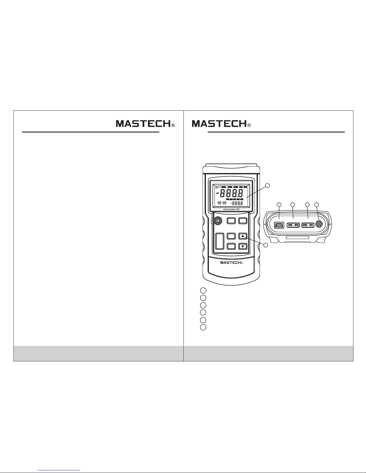
3.1 Components
USB po rt ( MS6513 and MS6514 o nl y)
Ther mo couple T1 input
Ther mo couple T2 input (MS6512 and M S6514 only)
Meas ur e under normal temp er ature
Disp la y
Key
4
3
2
1
5
6
Page 5

05 06
3.2 Display
Auto ma tic power-off indicator
Low ba tt ery indicator. Bat te ry should be
repl ac ed.
Ther mo couple measurem en ts include a
devi at ion value
Stat us s etup indicator wi th f lashing display
Indi ca tor to display save d da ta
Indi ca tor to save data auto ma tically with
flas hi ng display
Data h ol d state
Main d is play unit
Main d is play
Auxi li ary display unit
Auxi li ary display
USB po rt
Time display
Indi ca te time display min : se c
Indi ca te calibrating st at e
Indi ca te auto-save time s et ting
Indi ca te time display hou r: m in
Indi ca te thermocouple t yp e
3.3 Keys Description
POWER
HOLD
ENTER
SETUP
MAX
MIN
AVG
TC TYPE
C°/F°K
POWER
HOLD
ENTER
SETUP
MAX
MIN
AVG
T1/T2/T1-T2
C°/F°K
MS65 11 Key MS65 12 K ey
1
2
3
4
5
6
7
8
13
19
20
18
17
16
15
14
12
Indi ca tor to save data
11
9
10
MAX, M IN , AVG
12
11
10
9
8
765
4321
20
19
18
17
16 15
14
13
OFFS ET SETUP
READ REC H OLD
K
°F
°C
K
°F
°C
T1 T2
:
min :sec
CAL
TYPE KJTERSN
INTERVAL hour:min
T1-T2
T1 T2
USB
MAX AVG M ENMIN
mV
Page 6

07 08
Powe r on o r off th er mometer
Ther mo couple type selec ti on
(MS6 511, MS65 13 )
POWE R
TC TYPE
Select to display T1, T2 and T1-T2
(temperature difference
measurement) on main or auxiliary
screen alternately (MS6512, MS6514)
T1/T2/
T1-T2
Unit selection: Celsius (°C),
Fahrenheit (°F), Kelvin (K)
˚C/˚F/K
MAX/MIN
/AVG
View maximum, minimum and
average value. Long press to close
Data hold
HOLD
To confirm, see user setting for details
To set, see user setting for details
Long press to open USB, long press
again to turn off USB
PCLink
SETUP
ENTER
(MS6513 and MS6514 only)
To change setting options or add
functions, see specific operation
for details
To change setting options or reduce
functions, see specific operation for
details
Read saved data (only for MS6513
and MS6514)
Save current data (only for MS6513
and MS6514)
MEM
READ
POWER
PClink
MEM
READ
HOLD
ENTER
SETUP
MAX
MIN
AVG
T1/T2/T1-T2
C°/F°K
MS65 14 K ey
POWER
PClink
MEM
READ
HOLD
ENTER
SETUP
MAX
MIN
AVG
TC TYPE
C°/F°K
MS65 13 K ey
Page 7

09 10
4. Setting Meter
4.1 SETUP Option
Pres s th e SETUP ke y to enter setup mode . “ ”
symb ol w ill flash on the scre en , Press it again to
swit ch s etting states seq ue ntally. Save all previous
sett in gs before exiting . If t he meter is turned off in
the pr oc ess of setting, set ti ng changes will not b e
save d. C hanged settings w il l take effect
imme di ately after exiti ng s etup mode.
Loop s eq uence: data stora ge i nterval setting
(INT ERVAL) - thermoco uple type setting ( TY PE)
- OFFS ET (T1) se tt ing - OFFSET (T2) setting auto ma tic power-off time settin g - system time
sett in g (S-T) - power frequ en cy setting (LinE) norm al t emperature comp en sation (NTC) swit ch
sett in g - auto-calibrat io n switch setting (C AL ) data c le aning (CLr) - save se tt ing and return to
norm al m easurement stat e (i f self-calibrat io n is
set to O N, r eturn to the calibr at ion state, then tur n
the me te r off an d re start to return to no rm al
meas ur ement state).
Note: on ly MS6512 and MS651 4 ha ve OFFSET
(T2) o pt ion.
Only M S6 513 and MS6514 have d at a storage
inte rv al setting (INTERVAL) and data cle an ing
(CLr ) op tions.
4.2 SETUP Option Setting
1. Dat a st orage interval se tt ing (INTERVAL ):
Pres s th e SETUP to e nter the data stora ge
inte rv al setting mode. “ ” will f lash on the
scre en . Use ▼ to change autom at ic data
stor ag e time interval. Ho ld ▼ t o quickly
incr ea se or decrease sett in g time. Maximum
inte rv al time is 59:59, min im um interval time
is 00: 00 ( 00:00 enables aut om atic data storage
func ti on; it only can be stor ed m anually).
2. Thermocou ple type setting (TYP E)
Ente r th ermocouple type s et ting mode. Use
to set the rmocouple types : K, J , T, E (for MS 65 13
and MS 65 14, R, S, N can be set, too . Fo r MS6511
and MS 65 13, thermocoupl e ty pes can be
swit ch ed directly with “T C TYPE” ke y)
3. OFF SE T (T1) s et ting
User s ca n adjust the thermo me ter displayed
valu e to c ompensate for a cer ta in kind of
ther mo couple error. See “A dj ust the temperatu re
sens or e rror with deviati on v alue” section.
Allow ab le adjustment ran ge i s ±6°C.
After e nt ering OFFSET (T1) setting s ta te, the
offset value s et ting can be changed w ith .
Note: Wh en this offset value is n o longer
requir ed, please restore th is offset value to 0.0.
Changi ng the thermocouple t ype will
automa tically restore off set value to 0.0.
SETUP
SETUP
Page 8

11 12
4. OFF SE T(T2) setting
User s ca n adjust the thermo me ter show value to
comp en sate for a certain ki nd o f thermocouple
erro r. Se e “Adjust the tempe ra ture sensor error
with d ev iation value” sec ti on. Allowable
adju st ment range is ±6°C.
After e nt ering OFFSET (T2) setting s ta te, the
offset value s et ting can be changed w ith ▼ .
Note: Wh en this offset value is n o longer
requir ed any more, please res tore this offset
value to 0 .0. Changing the ther mocouple type
will aut omatically restor e offset value to 0.0.
5. Auto ma tic power-off time settin g (P)
Ente r th e automatic power -o ff tim e se tting mode.
“P-” w il l show on the screen. S et a utomatic
powe r- off ti me ( 5 to 60 minutes) with ▼ . H old
▼ to qui ck ly increase or decr ea se. Set the
slee p ti me less than 5 minute s to s how “OFF”,
turn s off the au to matic power-off functio n.
When a ut omatic power-off functi on is active,
“ ” will sho w on the screen; othe rw ise, it
won' t di splay.
Autom at ic power-off time is counte d from last
key op er ation.
When t he t hermometer is in au to matica data
reco rd ing and PC communic at ion state, it won't
ente r au tomatic power-o ff state
6. Sys te m time setting (S-T )
System t ime is the time from po we ring on. It will
auto ma tically be cleare d af ter power failure .
Ente r th e system time setti ng . “S-T” will show
on the s cr een. The s ystem time can be set w it h
▼ .
Pres s EN TER key to select tim e fo rmat, including
“hou r: min” or “min:sec” . Ho ld ▼ to quickly
incr ea se or decrease. If th is s etting is not chang ed ,
the sy st em time is the curren t th ermometer
runn in g time.
7. Pow er f requency settin g (L inE)
To ge t th e best measuremen t re sults, please set
the ther mometer's power f re quency to local usa ge
Enter th e power frequency s et ting. “LinE” will
show on th e screen. Select an d se t interference
freque ncy to 50Hz or 60Hz wit h ▼ .
8. Nor ma l temperature com pe nsation (NTC)
switch s etting Enter the no rm al temperature
compen sation (NTC) swit ch s etting mode. “NTC ”
will s ho w on the screen. By def au lt, it is in ON
state up on booting. ON/OF F ca n be set for
normal t emperature comp en sation with ▼ .
The thermome te r will automatica ll y restore to
ON state a fter reboot.
9. Auto -c alibration swit ch s etting (CAL)
Enter th e ON/OFF setting of aut o-calibration
(CAL) mo de. “CAL” will show o n th e screen. By
defaul t, it is in OFF state upon bo oting. ON/OFF
can be set f or calibration fu nc tion with ▼ . By
settin g this item to ON, users ca n enter the
calibr ation mode. See “Us er S elf-Calibrati on ”
for deta ils.
Note: Us e this function with ca ution!
10. Da ta c learing (CLr)
Enter th e data clearing (CL r) m ode. “CLr” will
show on th e screen, then pres s “E NTER” to
clear al l recorded data. At th e sa me time, “CLr”
will fla sh on the screen. It wi ll s top flashing
immedi ately after data is c le ared.
Page 9

13 14
5. Using The Meter
5.1 Connecting Thermocouple
1. Ins er t the thermocoupl e to i nput jack
2. Pre ss t he power key to turn on t he
ther mo meter power
3. Set t he t hermocouple typ e to b e consistent
with t he i nserted thermoc ou ple type
Note: If t he thermocouple is no t connected to
the sele cted input end or the the rmocouple is
“open” , or when it exceeds meas uring range,
“OL” wil l show on the thermomet er.
5.2 Displaying Temperature
1. Pre ss ° C/°F/K key to selec t ap propriate
temp er ature unit
2. Put t he t hermocouple to th e te sting position
3. Mea su rement results wi ll d isplay on the scree n
5.3 Data Hold
1. Pre ss H OLD to keep reading o n th e screen.
“ ” will s ho w on the screen
2. Pre ss H OLD key again to clos e “H OLD” function
and re st ore measurement s ta te.
5.4 Viewing MAX, MIN and AVG Readings
1. Pre ss M AX/MIN/AVG key to view MAX, MI N
and AVG readings .
2. Hol d MA X/MIN/AVG key to exit MAX/MI N/ AVG
view m od e
5.5 Use offset Value To Adjust
Temperature Probe Error
Use OF FS ET (T1 ) an d OFFSET (T2) in the SETUP
opti on t o adjust the thermo me ter readings to
comp en sate for a certain ki nd o f thermocouple er ro r.
1. Put t he t hermocouple in a kn ow n and stable
temp er ature environme nt ( such as in ice bath or
dry we ll c alibrator)
2. Sta bi lize the temperat ur e reading
3. Und er t he SETUP option, adjust OFF SE T va lu e
unti l th e temperature rea di ng on the auxiliary
disp la y is consistent wit h th e calibrated
temp er ature (see “SETUP Option Se tt ing”).
5.6 User Self-Calibration
Afte r us ers enter calibra ti on mode, the meter ca n
be cal ib rated. Calibrat io n points and calibr ation
meth od s are shown here:
1. Cal ib ration point:
a) Nor ma l Temper at ure 25°C
b) T1 in pu t channel, 0μV and 40 .0 00mV
c) T2 in pu t channel, 0μV and 40 .0 00mV (only for
MS6512 a nd MS6514)
2. Cal ib ration methods:
a) Put the t hermometer into a t he rmotank with
the temp erature of 25°C for 3 to 5 mi nutes.
b) Pow er o n the thermometer t o st abilize the
thermo meter.
c) Set sel f-calibration ( CA L) to ON state in the
“SETUP ” setting option, a nd e xit setting state .
It will re turn to the calibra ti on state.
d) Adju st t he screen tempera tu re with ▼ keys
until th e temperature is co ns istent with the
thermo tank.
HOLD
Page 10

16
e) Pre ss “ ENTER” key to save th e cu rrent
cali br ation value.
f) Pre ss “ T1/T2/T1-T2” ke y (o r “TC TY PE ” key) to
swit ch t o T1 mea su rement channel.
g) Inp ut 0 μV in T1 m ea surement channe l
h) Afte r st abilizing, pres s “E NTER” key to save the
curr en t calibration val ue .
i) Inp ut 4 0.000mV in T1 measurement c hannel
j) Afte r st abilizing, pres s “E NTER” key to save the
curr en t calibration val ue .
k) Pre ss “ T1/T2/T1-T2” ke y to s witch to T2
meas ur ement channel.
l) Inp ut 0 μV in T2 m ea surement channe l
m) Afte r st abilizing, pres s “E NTER” key to save
the cu rr ent calibration v al ue.
n) Inp ut 4 0.000mV in T2 measurement c hannel
o) Afte r st abilizing, pres s “E NTER” key to save the
curr en t calibration val ue .
p) Pow er o ff and r es tart to complete ca libration.
Note: Ma ke sure your standard s ource is
accura te, then make calibra tion. The user is
respon sible for using an accu rate calibration
source . If the meter is inaccur ate due using an
inaccu rate calibration so urce, the user bears
the liab ility.
15
6. Data Storage
6.1Data Storage
Data i s st ored with two metho ds : manual storage
and au to matic storage
1. Man ua l storage is in the nor ma l measurement
mode , an d data storage inte rv al (INTERVAL) i s
set to “00 :00”. Press the “ME M” k ey to store an
item o f da ta. Th e st orage location is t he s mallest
numb er i n the unused storag e sp ace. When
stor ag e space is full of data , “F ULL” character
will d is play for two second s.
2. Auto ma tic storage is in the n or mal measurement
mode , an d data storage inte rv al (INTERVAL) i s
not se t to “ 00:00”. Press the “ ME M” key to start
stor in g data. Th e storage locatio n is the smallest
numb er i n the unused storag e sp ace. At t he
same t im e, “ ” symbol will flas h on t he screen.
Pres s th e “MEM” key again to st op s toring data.
Each d at a storage time inte rv al is the time set in
the da ta s torage interval s et ting (INTERVAL).
The minimum ti me i nterval which can b e set is 1
seco nd , the maximum time in te rval is 59 minutes
and 59 s ec onds. When storag e sp ace is full of
data , “F ULL” character wi ll d isplay for two
seco nd s, and stop storing d at a.
6.2 Data Reading
In the n or mal measurement m od e, press the “READ”
key to e nt er data reading mod e. At t he same time,
“ ” symb ol w ill flash on the scre en . Press ▼ to
read t he n ext data forward or b ac kward. Hold ▼ ▲
to qui ck ly move forward or ba ck ward in the stored
data . At th e same time, “ ” and numb er will shown
on the a ux iliary display. If there is no a vailable
stor ag e space, “NULL” cha ra cter will display f or
two se co nds.
REC
MEM
READ
Page 11

1817
7. Data Transmission
6.3 Clearing Stored Data
Ente r th e “Data Clearing (C Lr )” item in the SETUP
opti on . “CLr” will show on th e sc reen. Phen press
“ENT ER ” to clear all record ed d ata. At t he s ame
time , “C Lr” will flash on the s cr een. It will stop
flas hi ng immediately af te r clearing data.
Conn ec t the thermometer t o PC w ith data line.
Hold “ PC Link” key. “ ” symbol will show on t he
scre en . At this time, the USB po rt o f the
ther mo meter is opened. Se e da ta transmission
prot oc ol for details.
Note: After connecti ng the USB, the thermom eter
will be po wered by USB power supp ly and the
thermo meter's power key is in valid. After
discon necting, the USB key wi ll become valid.
8. Meter Maintenance
8.1 Replace Battery
When t he b attery indicato r “ ” ap pears on the
ther mo meter, the battery s ho uld be replaced
imme di ately. The proc edure is:
1. Turn o ff the the rm ometer power
2. Rel ea se the battery cove r sc rew to remove the
batt er y cover
3. Rep la ce with 9V battery
4. Put t he b attery cover back a nd t ighten screw.
8.2 Clean
When t he t hermometer surf ac e is dirty and cleani ng
is req ui red, use a soft cloth o r sp onge to wipe gently
with a l it tle clear water, soa p wa ter or commercial
dete rg ent. To avoid dama ge, don't immerse the
ther mo meter in water.
9.Technical Data
The in di cator is accurate w it hin the temperatu re
rang e fr om 18°C to 28°C, when r el ative humidity is
not mo re t han 80%. Warra nty period is one yea r
(not i nc luding thermoco up le error).
Func ti on
MS6511 MS6512
MS6513
MS6514
Thermocouple
type
K, J, T, E
K, J, T, E, R, S, N
Measurement
channel
T1
T1/T2
T1
T1/T2
K: -200.0°C to +1372°C
-328.0°F to +2501°F
J: -210.0°C to +1200°C
-346.0°F to +2192°F
T: -250.0°C to +400°C
-418.0°F to +752°F
E: -150.0°C to +1000°C
-238.0°F to +1832°F
R: 0°C to +1767°C
32°F to +3212°F
S: 0°C to +1767°C
32°F to +3212°F
N: -200.0°C to +1300°C
-328.0°F to +2372°F
Measurement
range
Display
resolution
0.1°C/ °F / K<1000° (1°C/ °F / K for
R-type and S-type)
1°C/ °F / K >1000°
±[0.5% +0.5°C]
K,J,T,E:±(0.2%+0.5°C)
R,S:±(0.2%+1°C)
N:±(0.2%+0.5°C)
Precision T1/
T2/T1-T2
USB
Page 12

HYS007044
19
<-10°C: within +0.5°C; <-200°C:
within +1°C
T-type < -200°C for reference only
Relative time Time
0~999, 1000 groups in total
Temperature
scale
Data record
ITS-90
NIST-175
Applicable
standard
Recording interval setting*,
thermocouple type setting,
thermocouple offset setting, automatic
power-off time setting, system time
setting, power frequency setting,
temperature compensation switch
setting, self-calibration switch setting,
data clearing*
Setting
functions
9V Battery
Power supply
*MS6513, MS6514
 Loading...