

Page 1

MS6231
DIGITAL
ENGINE ANALYZER
OPERATOR ’ S MANUAL
SAFETY INFORMATION
WARNING
To
ensure safe operation, and in order to exploit to the full the functionality of the meter, please follow
the directions in this section carefully.
This multimeter has been designed according to IEC-1010 concerning electronic measuring instruments
with an overvoltage category CAT ( ( ( 600V and pollution 2.
Follow all safety and operating instructions to ensure that the meter is used safely and is kept in good
operating condition.
With proper use and care, the digital meter will give you years of satisfactory service.
1.1 PRELIMINARY
1.1.1 When using the meter, the user must observe all normal safety rules concerning:
( Protection against the dangers of electrical current.
( Protection of the meter against misuse.
1.1.2 When the meter is delivered, check that it has not been damaged in transit.
1.1.3 When poor condition under harsh preservation or shipping conditions caused, inspect and confirm
this meter without delay.
1.1.4
Test
leads must be in good condition. Before using verify that the insulation on test leads is not
damaged and/or the leads wire is not exposed.
1.1.5 Full compliance with safety standards can be guaranteed only if used with test leads supplied. If
necessary, they must be replaced with the same model or
same electric ratings.
1.2 DURING USE
1.2.1 Before using, you must select the right input jack, function and range.
1.2.2 Never exceed the protection limit values indicated in specifications for each range of measurement.
1.2.3 When the meter is linked to a measurement circuit, do not touch unused terminals.
1.2.4 At the manual range, when the value scale to be measured is unknown beforehand, set the range
selector at the highest position.
1.2.5 Do not measure voltage if the voltage on the terminals exceeds 600V above earth ground.
1.2.6 Always be careful when working with voltages above 60V DC or 30V AC rms, keep fingers behind
the probe barriers while measuring.
1.2.7 Never connect the meter leads across a voltage source while the transform switch is in the current,
resistance, temperature, diode or continuity mode. Doing so can damage the meter.
Page 2

1.2.8 Before rotating the transform switch to change functions and ranges, disconnect test leads from the
circuit under test.
1.2.9 Never perform resistance, temperature, diode and continuity measurements on live circuits.
1.2.10 Never use the meter under the condition of the explosive air, steam or dirt.
1.2.11 If any faults or abnormalities are observed, the meter can not be used any more and it has to be
checked out.
1.2.12 Never use the meter unless the rear case is in place and fastened fully.
1.2.13 Please do not store or use meter in areas exposed to direct sunlight, high temperature, humidity or
condensation.
1.3 SYMBOLS
Important safety information, refer to the operating manual.
Double insulation ( Protection class ( ( ) .
CAT III Overvoltage (Installation) category III, Pollution Degree 2 per IEC1010-1 refers to the level of
Impulse Withstand Voltage protection provided.
Conforms to european union directive
Earth ground
AC Alternating current
DC Direct current
Diode
Continuity buzzer
AC or DC (alternating current or direct current)
Engine dwell
RPM Round per minute
× 10 Reading multiplies 10
Measurement with clamp (optional), widening the field of applications of the meter
℃ Centigrade
℉ Fahrenheit
MAX-H The maximum value is being held.
DAT A-H This indicates that the display data is being held.
AUTO Auto range
The battery is not sufficient for proper operation.
1.4 MAINTENANCE
1.4.1 Please do not attempt to adjust or repair the meter by removing the rear
case while voltage is being applied.Atechnician who fully understands danger involved should only carry
out such actions.
1.4.2 Before opening the battery cover or case of the meter, always disconnect test leads from all tested
circuits.
1.4.3
To
avoid the wrong reading causing electricity attack, when the meter displays “ ” , you must
change the battery.
1.4.4 Do not use abrasives or solvents on the meter, use a damp cloth and mild detergent only.
1.4.5 Always set the power switch to the OFF position when the meter is not in use.
1.4.6 If the meter is to be stored for a long period of time, the batteries should be removed to prevent
damage to the unit.
2. DESCRIPTION
Page 3

- This meter is a portable professional measuring instrument with handsome LCD and back light easily
reading.
- Single operation of a transform switch makes measurement convenient. Overload protection and low
battery indication are provided, this meter is ideal for use in the fields, workshop, school, hobby and
home applications.
- This meter has function of auto range and manual range.
- This meter has function of auto warning.
- This meter has function of auto power off.
- This meter is with the functions of data hold and maximum value hold.
- When using, it can show ranges engineering unit enunciators measuring results.
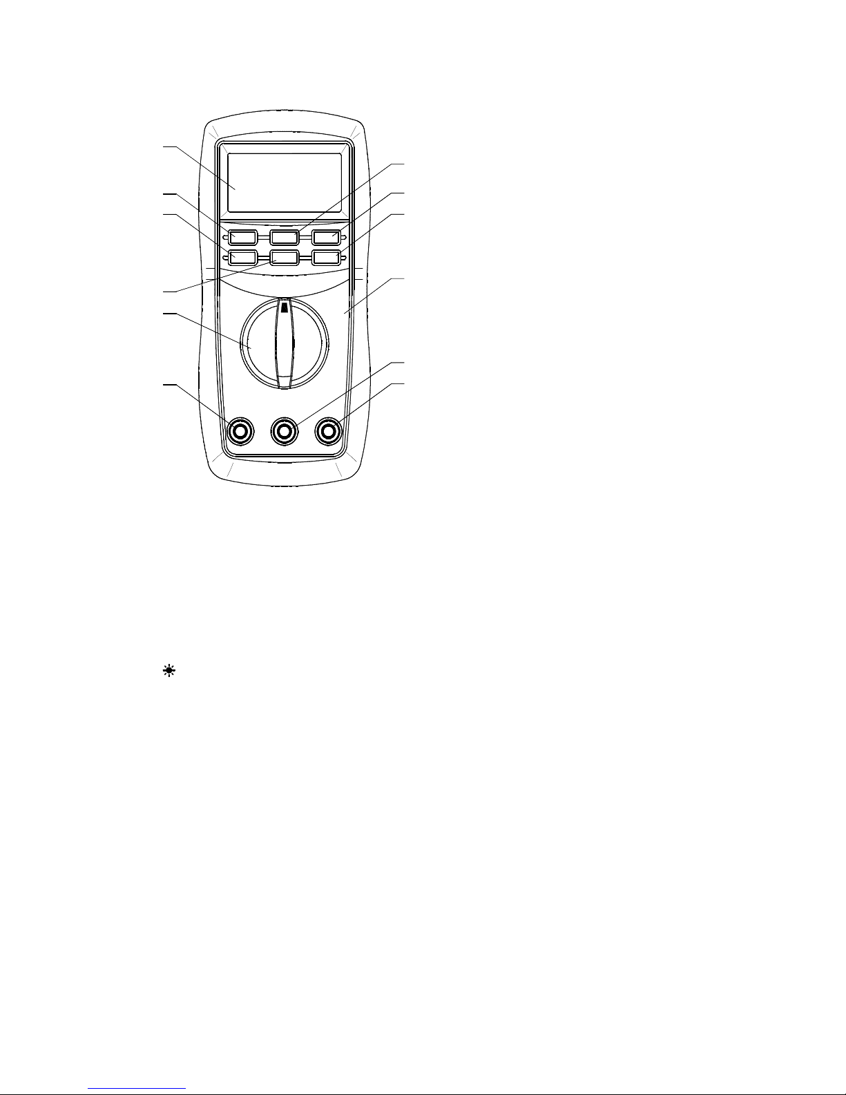
2.1 NAMES OF COMPONENTS
⑴ LCD Display
⑵ ON/OFF Button
⑶ RANGE Button
⑷ FUNC. Button
⑸ Transform Switch
⑹ 10A Jack
⑺ INPUT Jack
⑻ COM Jack
⑼ Panel
⑽ Button
⑾ DAT A-H Button
⑿ MAX.H Button
2.2 SWITCH, BUTTONS AND INPUT JACK ELUCIDATION
( ON/OFF Button
This Button is used to the switch of power.
Page 4
(1)
(2)
(3)
(4)
(5)
(6)
(10)
(11)
(9)
(7)
(8)
(12)
( RANGE Button
This button is used to transform Auto range or manual range.
( FUNC. Button
This button is used to transform function.
( DAT A-H Button
This Button is used to the switch of data hold.
( MAX.H Button
This Button is used to the switch of maximum value hold.
( Button
This button is used to the switch of back light.
( Transform Switch
This switch is used to select functions and desired ranges.
( 10A Jack
Input terminal for current 0 ~ 10A.
INPUT Jack Input terminals except A.
COM Jack
Common terminal for measurement.
Page 5

3. SPECIFICATIONS
Accuracy is specified for a period of year after calibration and at 18 ℃ to 28 ℃ ( 64 ( F to 82 ( F ) with relative
humidity to 75%.
3.1 GENERAL SPECIFICATIONS
3.1.1 Auto ranges and manual range.
3.1.2 Overrange protection for all ranges.
3.1.3 Max. Voltage Between T erminals And Earth Ground: 600V DC or AC
3.1.4 Operating Altitude: 2000 meters (7000 ft.) maximum
3.1.5 Display: 16mm LCD
3.1.6 Max. Show V alue: 1999 (3 1/2)
3.1.7 Polarity Indication: ‘ - ’ indicates negative polarity.
3.1.8 Overrange Indication: Display ‘ OL
’
3.1.9 Sampling Time: approx. 0.4 second
3.1.10 Unit showing: showing of function and electrical capacity.
3.1.11 Low Battery Indication: ‘
’
displayed
3.1.12 Auto power off time: 15 min.
3.1.13 Power Supply: 1.5V × 3 AAA battery.
3.1.14 Operating Temperature: 0 ℃ to 40 ℃ ( 32 ( F to 104 ( F )
3.1.15 Storage T emperature: -10 ℃ to 50 ℃ ( 10 ( F to 122 ( F )
3.1.16 Dimension: 158 × 74 × 32 mm
3.1.17 Weight: approx. 250g ( including battery )
3.2 ELECTRICAL SPECIFICATIONS
Circumstance Temperature: 23 ( 5 ℃ Relative Humidity: < 75%
3.2.1 DC Voltage
Range Resolution Accuracy
200mV 0.1mV
2V 0.001V
20V 0.01V
( ( 0.7% of rdg + 2 digits )
200V 0.1V
600V 1V
- Input Impedance: 10M (
- Overload Protection:
200mV range: 250V DC or AC rms, 2V-600V ranges: 600V DC or AC rms.
- Max. Input Voltage: 600V DC
Page 6

3.2.2 AC V oltage
Range Resolution Accuracy
200m
V
0.1mV
2V 0.001V
( ( 0.8% of rdg + 3 digits )
20V 0.01V
200V 0.1V
600V 1V ( ( 1.0% of rdg + 3 digits )
- Input Impedance: 10M (
- Overload Protection:
200mV range: 250V DC or AC rms, 2V-600V ranges: 600V DC or AC rms.
- Frequency Range: 40 to 400Hz
- Response: Average, calibrated in rms of sine wave.
- Max. Input Voltage: 600V rms AC
3.2.3 DC Current
Range Resolution Accuracy
2.000
A
0.001A
( ( 2.0% of rdg + 10
digits )
10.00
A
0.01A
- Overload Protection: unfused.
- Max. Input Current:: 10A
- voltage drop : 2A range: 20mV ,
10A range: 200mV
3.2.4 AC Current
Range Resolutio
n
Accuracy
2.000
A
0.001A ( ( 3.0% of rdg + 10 digits )
10.00
A
0.01A
- Overload Protection: unfused.
- Max. Input Current:: 10A
- Frequency Range: 40 to 400Hz
- Response: Average, calibrated in rms of sine wave.
- voltage drop : 2A range: 20mV ,
10A range: 200mV
3.2.5 DC Current ( with clamp, optional )
Range Resolut
ion
Accuracy
mete
r 200A
0.1mV
/0.1A
( ( 1.2 % of rdg + 3
digits )
(DC)
Cla
0
to 200A
0.1A
/0.1mV
Typical ( ( 2.0 % )
Page 7
mp
mete
r 2000A
1mV/1
A
( ( 1.2 % of rdg + 3
digits )
(DC)
Cla
mp
0
to
2000A
1A
/1mV
Typical ( ( 2.0 % )
- Overload Protection: 250V DC or 250V rms AC.
- Max. Input Voltage: 200mV
3.2.6 AC Current ( with clamp, optional )
Range Resolut
ion
Accuracy
mete
r 200A
0.1mV
/0.1A
( ( 1.5 % of rdg + 5
digits )
(DC)
Cla
mp
0
to 200A
0.1A
/0.1mV
Typical ( ( 3.0 % )
mete
r 2000A
1mV/1
A
( ( 1.5 % of rdg + 5
digits )
(DC)
Cla
mp
0
to
2000A
1A
/1mV
Typical ( ( 3.0 % )
- Overload Protection: 250V DC or 250V rms AC.
- Max. Input Voltage: 200mV
- Frequency Range: 40 to 400Hz
- Response: Average, calibrated in rms of sine wave.
3.2.7 Resistance
Range Resolutio
n
Accuracy
200 ( 0.1 ( ( ( 1.0% of rdg + 3 digits )
2k ( 0.001k ( ( ( 1.0% of rdg + 1 digit )
20k ( 0.01k ( ( ( 1.0% of rdg + 1 digit )
200k ( 0.1k (
( ( 1.0% of rdg + 1 digit )
2M ( 0.001M (
( ( 1.0% of rdg + 1 digit )
20M ( 0.01M ( ( ( 1.0% of rdg + 5 digits )
- Open Circuit Voltage: 0.25V
- Overload Protection: 250V DC or 250V rms AC
3.2.8 Continuity
Range Function
Built-in buzzer will sound, if
resistance is lower than 50 ( .
- Open circuit voltage: approx. 0.5V
- Overload Protection: 250V DC or 250V rms AC
Page 8

3.2.9 Temperature
Range -20 ℃ to 1000 ℃
Resolution1 ℃
-20 ℃ to 0 ℃ ( ( 5% of rdg +
4digits )
Accurac
y
0 ℃ to 400 ℃ ( ( 1% of rdg +
3digits )
400 ℃ to
1000 ℃
( ( 2% of rdg +
3digits )
Range -0 ℉ to 1800 ℉
Resolution1 ℉
-0 ℉ ~50 ℉ ( ( 5% of rdg +
4digits )
Accurac
y
50 ℉ ~750 ℉ ( ( 1% of rdg +
3digits )
750 ℉ ~1800
℉
( ( 2% of rdg +
3digits )
- Overload Protection: 250V DC or rms AC
3.2.10 Engine Dwell
Range Resolution Accuracy
4CYL 0.1 º ( ( 3 º )
6CYL 0.1 º ( ( 3 º )
8CYL 0.1 º
( ( 3 º )
- Overload Protection: 250V DC or rms AC
3.2.11 Engine Rev
Range Resolutio
n
Accuracy
4CYL 10RPM
6CYL 10RPM ( ( 3.0% of rdg + 3 digits )
8CYL 10RPM
- Overload Protection: 250V DC or rms AC
3.2.12 Diode
Rang
e
Resolutio
n
Function
1mV Display :read approximate
forward voltage of diode.
- Forward DC Current: approx. 1mA
- Reversed DC Voltage: approx.1.5V
- Overload Protection: 250V DC or rms AC
4. OPERATING INSTRUCTION
4.1 POWER-UP
Press the “ ON/OFF ” button to turn the meter ON or OFF.
Page 9

4.2
DATA
HOLD
If you need data hold when measuring, you can put on “ DAT A-H ” button, it will hold the reading; if you put
the button again, data hold is not continue.
4.3 MAXIMUM VALUE HOLD
If you need data hold when measuring, you can put on “ MAX.H ” button, it will hold the maximum value; if
you put the button again, maximum value hold is not continue.
4.4 FUNCTION TRANSFORM
Put down the "FUNC." when measuring the current and voltage. Meter will be transformed between DC
and AC range. Put "FUNC." when measuring the temperature, meter will transform between ℃ and ℉
range. Put "FUNC." when measuring the diode and continuity, meter will transform among them.
4.5 RANGE TRANSFORM
The auto range is used when measuring the current, voltage and resistance. Put down the "RANGE" if
the manual range is needed. Each time you put down, range will go upward; the minimum range is
transformed if "RANGE" is put down at the maximum range. If the "RANGE" is put down more than two
seconds, auto range is used again.
4.6 BACK LIGHT
If the light is dark to make the reading difficult when measuring, you can press “ ” button to turn on the
back light, which will last for 15 seconds. Continuous pressing the button for two seconds will turn off the
back light.
NOTE:
( LED is the main source of back light. Its working current is large, although the meter has the timer
equipment (time is 15 seconds and it will off automatically after 15 seconds); often use back light will
shorten the battery life, you ’ d better not to use the back light so frequently if it ’ s not necessary.
( When the battery voltage is less than 3.8V, it will show “ ” . But if you use back light at the same time,
maybe “ ” will come up even if the battery voltage is more than 3.8V , because the working
current is higher and the voltage will decline. (When “ “ shows, the accuracy of the measurement can
not be assured.) You need not replace the battery. When you use normally (back light is not using),
“ ” will not show up. You need replace it till “ ” show again.
4.7 AUTO WARNING
If the input voltage is larger than 2V at the range and if the input current is larger than 10A, buzzer
will have a long sound
4.8 AUTO POWER OFF
( If there ’ s no any operation within fifteen minutes after power is on, meter will auto power off with five
short sounds and a long sound in a minute.
( After auto power off, if stir the transform switch or put down any button of “ FUNC. ” ,
“ DATA-H ” , ” MAX.H ” , ” RANGE ” , meter will recover the working condition. ( If presses the “ FUNC ” when
power is on, auto power off disable.
4.9 PREPARATION FOR MEASUREMENT
4.3.1 Put on the “ ON/OFF ” button. If the battery voltage is less than 3.8V, display will show “ ” , the
battery should be changed at this time.
4.3.2 The “ ” besides the input jack shows that the input voltage or current should be less than
specification on the sticker of the meter to protect the inner circuit from damaging.
4.3.3 Select a function and a range for the item to be measured through rotating the transform switch
Page 10

accordingly. When the value scale to be measured is unknown beforehand, set the range selector at the
highest position.
4.3.4 When connection, first connect to the public testing line, then to the electriferous testing line. When
you ’ ll remove it, you should remove the elecriferous one.
4.10 MEASURING DC VOLTAGE
WARNING
You can ’ t input the voltage which more than
600V DC, it ’ s possible to show higher voltage,
but it ’ s may destroy the inner circuit.
Pay attention not to get an electric shock when
measuring high voltage.
4.10.1 Connect the black test lead to the COM jack and the red test lead to the INPUT jack.
4.10.2 Set the transform switch at the V range position.
4.10.3 Put down the "FUNC." to enter the DC measurement. Auto range or manual range can be
transformed by
putting the “ RANGE ” .
4.10.4 Connect test leads across the source or load under measurement.
4.10.5 You can get a reading from LCD display. The polarity of the red test lead connection will be
indicated.
NOTE:
( At the little voltage range, the meter will show unsteady reading when test leads haven ’ t reach the circuit,
it ’ s normal because the meter is very sensitivity. When test leads touch the circuit, you can get the true
reading.
( At the manual range mode, when only the figure ‘ OL’is displayed, it indicates overrange situation and
Page 11

the higher range has to be selected.
( At the manual range mode, when the value scale to be measured is unknown beforehand, set the range
selector at the highest position. Application 1: Use 2V range to test the end state of the divider.
Take the high voltage line away from the cover of the divider, then connect with the iron.
The red test lead is connected with the low voltage connection pole of the divider, or with the end “ - ” of the
ignition winding; the black test leads is connected with the iron or the negative pole of the storage cell.
Open the ignition switch for a little while, the meter will indicate the value lower than
1V.
Directly measure the voltage of the end ’ s both sides, it indicates the end is good if the value is less than
0.2V.
Application 2: Use 2V range to check the leakage of the storage cell.
The black test lead is connected with the iron or the pole “ - ” , the red one is connected with all ends of the
storage cell.If some value is indicated on the meter, the leakage is existed. The storage cell should be
cleaned or replaced.
Application 3: Use 20V range to check the load capability of the storage cell.
The black test lead is connected with the iron or the negative pole of the storage cell; the red one with the
positive pole of the cell.
Open the switch of the front light, of the flashing, of the ignition and of the radio respectively.
The above process should be finished in 2 minutes.
D. Check the value less than 11.7V or not, if it is, then the storage cell should be recharged or replaced.
Application 4: Use 20V range to check the capability of the storage cell.
Take the high voltage line away from the cover of the divider and connect to the iron.
The black test lead is connected with the iron or the negative pole of the storage cell, and the red one
with its positive pole.
Start the engine and 15 seconds later check if the indicating value is more than 9.1V; if it is not correct,
the engine should be checked or the storage cell should be recharged or replaced.
Application 5: Check the cable of the power supply.
While the engine is started, measure the voltage of the both sides of the cable.
4.11 MEASURING AC VOLT AGE
WARNING
You can ’ t input the voltage which more than
600V rms AC, it ’ s possible to show higher
voltage, but it ’ s may destroy the inner circuit.
Pay attention not to get an electric shock when
measuring voltage.
4.11.1 Connect the black test lead to the COM jack and the red test lead to the INPUT jack.
4.11.2 Set the transform switch at the V range position.
4.11.3 Put down the "FUNC." to enter the AC measurement. Auto range or manual range can be
transformed by putting the “ RANGE ” .
4.11.4 Connect test leads across the source or load under measurement.
4.11.5 You can get reading from LCD.
Page 12

NOTE:
( At the little voltage range, the meter will show unsteady reading when test leads haven ’ t reach the circuit,
it ’ s normal because the meter is very sensitivity. When test leads touch the circuit, you can get the true
reading.
( At the manual range mode, when only the figure ‘ OL’is displayed, it indicates overrange situation and
the higher range has to be selected.
( At the manual range mode, when the value scale to be measured is unknown beforehand, set the range
selector at the highest position.
4.12 MEASURING DC CURRENT
WARNING
Shut down the power of the tested circuit, then
connect the meter with the circuit for
measurement.
Page 13

4.12.1 Connect the black test lead to the COM jack and the red test lead to the 10A jack.
4.12.2 Set the transform switch at theArange position.
4.12.3 Put down the "FUNC." to enter the DC measurement. Auto range or manual range can be
transformed by putting the “ RANGE ” .
4.12.4 Connect test leads in series with the load under measurement.
4.12.5 You can get reading from LCD. The polarity of red test lead will be indicated.
NOTE:
( When only the figure ‘ OL’is displayed, it indicates overrange situation and the higher range has to be
selected.
( When the value scale to be measured is unknown beforehand, set the range selector at the highest
position. ( “ ” means the socket of 10A jack maximum current is 10A, no fuse protection.
4.13 DC CURRENT MEASURING
(WITH CLAMP, OPTIONAL)
4.13.1 Connect the black output lead of clamp to the COM jack and the red one to the INPUT jack of the
meter.
4.13.2 Set the transform switch at the ” ” range position.
4.13.3 Put down the "FUNC." to enter the DC measurement. Auto range or manual range can be
transformed by putting the “ RANGE ” .
4.13.4 Clamp the circuit under measured.
4.13.5 You can get reading from LCD. The polarity of red output lead will be indicated.
NOTE:
( At the manual range mode, when only the figure ‘ OL’is displayed, it indicates overrange situation and
the higher range has to be selected.
Page 14

( At the manual range mode, when the value scale to be measured is unknown beforehand, set the range
selector at the highest position.
( Select the DC clamp to measure the DC current.
( Matching problem about the meter and the sensitivity of the clamp:
a. The sensitivity of 200A range is 200mV , that of 2000A is 2V; the sensitivity of the matching clamp is
0.1A/0.1mV. The present indicated value is same to the measured value.
b. If the sensitivity of the selected clamp is low (0.1A/0.01mV), the indicated value will be 10 times lower
than the measured value. For example, the measured current is 100A, then the indicated value will be
10.0A.
c. If the sensitivity of the selected clamp is high (0.1A/1mV), the indicated value will be 10 times higher
than the measured value. For example, the measured current is 100A, then the indicated value will be
1000A.
4.14 MEASURING AC CURRENT
WARNING
Shut down the power of the tested circuit, then
connect the meter with the circuit for
measurement.
4.14.1 Connect the black test lead to the COM jack and the red test lead to the 10A jack.
4.14.2 Set the transform switch at theArange position.
4.14.3 Put down the "FUNC." to enter the AC measurement. Auto range or manual range can be
transformed by putting the “ RANGE ” .
4.14.4 Connect test leads in series with the load under measurement.
4.14.5 You can get reading from LCD.
NOTE:
( When only the figure ‘ OL’is displayed, it indicates overrange situation and the
Page 15

higher range has to be selected.
( When the value scale to be measured is unknown beforehand, set the range selector at the highest
position. ( “ ” means the socket of 10A jack maximum current is 10A, no fuse protection.
4.15 AC CURRENT MEASURING (WITH CLAMP , OPTIONAL)
4.15.1 Connect the black output lead of clamp to the COM jack and the red one to the INPUT jack of the
meter.
4.15.2 Set the transform switch at the “ ” range position.
4.15.3 Put down the "FUNC." to enter the AC measurement. Auto range or manual range can be
transformed by putting the “ RANGE ” .
4.15.4 Clamp the circuit under measured.
4.15.5 You can get reading from LCD.
NOTE:
( At the manual range mode, when only the figure ‘ OL’is displayed, it indicates overrange situation and
Page 16

the higher range has to be selected.
( At the manual range mode, when the value scale to be measured is unknown beforehand, set the range
selector at the highest position.
( Select the AC clamp to measure the AC current.
( Matching problem about the meter and the sensitivity of the clamp:
a. The sensitivity of 200A range is 200mV , that of 2000A is 2V; the sensitivity of the matching clamp is
0.1A/0.1mV. The present indicated value is same to the measured value.
b. If the sensitivity of the selected clamp is low (0.1A/0.01mV), the indicate value will be 10 times lower
than the measured value. For example, the measured current is 100A, then the indicated value will be
10.0A.
c. If the sensitivity of the selected clamp is high (0.1A/1mV), the indicated value will be 10 times higher
than the measured value. For example, the measured current is 100A, then the indicated value will be
1000A.
4.16 MEASURING RESISTANCE
WARNING
When measuring in-circuit resistance, be sure
the circuit under test has all power removed and
that all capacitors have been discharged fully.
4.16.1 Connect the black test lead to the COM jack and the red test lead to the INPUT jack.
4.16.2 Set the transform switch at the ( range position. Auto range or manual range can be transformed
by putting the “ RANGE ” .
4.16.3 Connect test leads across the resistance under measurement.
4.16.4 You can get reading from LCD.
NOTE:
( At the manual range mode, when only the figure ‘ OL’is displayed, it indicates overrange situation and
the higher range has to be selected.
( For measuring resistance above 1M ( , the meter may take a few seconds to get stable reading.
( When the input is not connected, i.e. at open circuit, the figure ‘ 1’will be displayed for the overrange
condition.
Page 17

4.17 MEASURING TEMPERATURE ( ℃ )
WARNING
To
avoid electrical shock, do not connect the
thermocouples with the electriferous circuit.
4.17.1 Set the transform switch at the TEMP range position.
4.17.2 Put down the "FUNC." to enter the ℃ measurement.
4.17.3 The LCD display will show the current environment temperature.
4.17.4 When measuring the temperature with thermocouple, ‘ K’type probe for this meter can be used.
Insert the black plug to the COM jack and the red one to the INPUT jack, touch the end of the
temperature sensor to the area or surface of the object for measurement.
4.17.5 You can get reading from LCD.
NOTE:
( With better hermetization, the meter ’ s temperature measured circuit and environment need a little
longer time to reach heat balance, and then accurate reading can be gotten.
4.18 MEASURING TEMPERATURE ( ℉ )
WARNING
To
avoid electrical shock, do not connect the
thermocouples with the electriferous circuit.
4.18.1 Set the transform switch at the TEMP range position.
4.18.2 Put down the "FUNC." to enter the ℉ measurement.
4.18.3 The LCD display will show the current environment temperature.
4.18.4 When measuring the temperature with thermocouple, ‘ K’type probe for
Page 18

this meter can be used. Insert the black plug to the COM jack and the red one to the INPUT jack, touch
the end of the temperature sensor to the area or surface of the object for measurement.
4.18.5 You can get reading from LCD.
NOTE:
( With better hermetization, the meter ’ s temperature measured circuit and environment need a little
longer time to reach heat balance, and then accurate reading can be gotten.
4.19 MEASURING ENGINE DWELL
4.19.1 Connect the black test lead to the COM jack and the red test lead to the INPUT jack.
4.19.2 Set the transform switch at the desired DWELL range position according to the measured cylinder
of the engine.
Page 19

4.19.3 Connect the black test lead to the iron or the negative pole of the storage cell, and the red one to
the low voltage connection pole of the divider or the negative pole of the ignition winding for
measurement.
4.19.4 You can get reading from LCD after the engine is started.
4.20 MEASURING REV
4.20.1 Connect the black test lead to the COM jack and the red test lead to the INPUT jack.
4.20.2 Set the transform switch at the desired TACH range position according to the measured cylinder of
the engine.
4.20.3 Connect the black test lead to the iron or the negative pole of the storage cell, and the red one to
the low voltage connection pole of the divider or the negative pole of the ignition winding for
measurement.
4.20.4 You can get reading from LCD after the engine is started.
4.21 TESTING DIODE
4.21.1 Connect the black test lead to the COM jack and the red test lead to the INPUT jack. (The polarity
of red lead is “ + ” )
4.21.2 Set the transform switch at the range position.
4.21.3 put down the "FUNC." transformed at test.
4.21.4 Connect the red lead to the anode, the black lead to the cathode of the diode under testing.
4.21.5 You can get reading from LCD.
NOTE:
( The meter will show the approximate forward voltage drop of the diode.
( If the lead connection is reversed, only
Page 20

figure ‘ OL ’ will be displayed.
( When the input is not connected, i.e. at open circuit, the figure ‘ OL’will be displayed.
4.22 CONTINUITY TEST
WARNING
When testing the circuit continuity, be sure that
the power of the circuit has been shut down and
all capacitors have been discharged fully.
4.22.1 Connect the black test lead to the COM jack and the red test lead to the INPUT jack.
4.22.2 Set the transform switch at the range position.
4.22.3 put down the "FUNC." transformed at continuity test.
4.22.4 Connect test leads across two points
Page 21

of the circuit under testing.
4.22.5 If continuity exists ( i.e., resistance less than about 50 ( ) , built-in buzzer will sound.
NOTE:
( If the input open circuit (or the circuit resistance measured is higher than 200 ( ), then the figure ’ 0L’will
be displayed.
5. MAINTENANCE
WARNING
Before attempting open the battery cover or case of
the meter, be sure that test leads have been
disconnected from measurement circuit to avoid
electric shock hazard.
5.1 BATTERY REPLACEMENT
WARNING
Before attempting open the battery cover of the
meter, be sure that test leads have been
disconnected from measurement circuit to avoid
electric shock hazard.
5.1.1 If the sign ‘ ’ appears on the LCD display, it indicates that the battery should be replaced.
5.1.2 Loosen the screw fixing the battery cover and remove it.
5.1.3 Replace the exhausted battery with a new one.
5.1.4 Put the battery cover as its origin.
5.2 TEST LEADS REPLACEMENT
WARNING
Full in compliance with safety standards can be
guaranteed only if used with test leads supplied. If
necessary, they must be replaced with the same
model or same electric ratings. Electric ratings of
the test leads: 1000V 10A.
You must be replaced the test leads if the lead is exposed.
6. ACCESSORIES
⑴
Test
Leads: Electric Ratings
1000V 10A
one piece
⑵ Battery: 1.5V, AAA three pieces
⑶ Operating Manual one piece
⑷ Thermocouple (K type) one piece
 Loading...