

Page 1
Ω
TEST
mA
VA
ms
Hz%
VA
ms
%
AC
L - N
L - E
N - E
Peak
Z - L
Z - N
Z - E
ASCC
12 A 15 A 20 A
HOLD
N
E
L
V Vd Z
RCD
GFCI
MS5908
Circuit Analyzer
Operation Manual
Page 2

01 02
General Instructions
This ci rcuit ana lyzer is a sp ecial tes t device
desig ned for AC low -voltag e distrib ution lin e quick
fault l ocation . With simp le operat ion, accu rate
measu rement an d other fea tures, it c an detect
multi ple probl ems on a line , such as cau sing to
elect ric shock , electri cal fire, a bnormal o peratio n
of equi pment, et c.
Functions:
• TRMS me asuring AC v oltage
Artif icial loa d 12A, 15A, 2 0A measuri ng line dro p
Measu ring phas e voltage , neutral l ine (zero l ine)
volta ge to earth , peak volt age, freq uency
Measu ring phas e (live lin e), neutr al line (ze ro line),
earth l ine condu ctor impe dance
Ident ifying 3- wire sock et connec tion mode ( zero
for lef t and live fo r right, ha ving eart h line or not )
Test the re liabili ty of resid ual curre nt device ( RCD)
and res ponse act ion time
Test the re liabili ty of GFCI ac tion and re sponse
actio n time
Backl ight func tion and da ta hold fun ction
•
•
•
•
•
•
•
Warning
Do not us e this inst rument wi thout rea ding,
under standin g and follo wing the in structi ons
in this m anual. Re ad and foll ow them car efully,
as well a s all warni ngs and ins tructio ns marked
on the in strumen t!
To prev ent damag es to the ins trument , it should
not be us ed for meas uring the o utput of UP S
equip ment, nor f or measur ing adjus table lig ht
and squ are wave ge nerator !
For mea suremen t accuren cy during r epeated
usage , allow at le ast 30 seco nds betwe en two
conse cutive me asureme nts to faci litate
equip ment cool ing when me asuring v oltage
drop an d cable imp edance.
To ensu re accura te measur ement dat a, please
check w hether th ere is impo rtant loa d or heavy
load in t he line bef ore testi ng. Turn of f the heavy
load, i f necessa ry, then re test.
Page 3
03 04
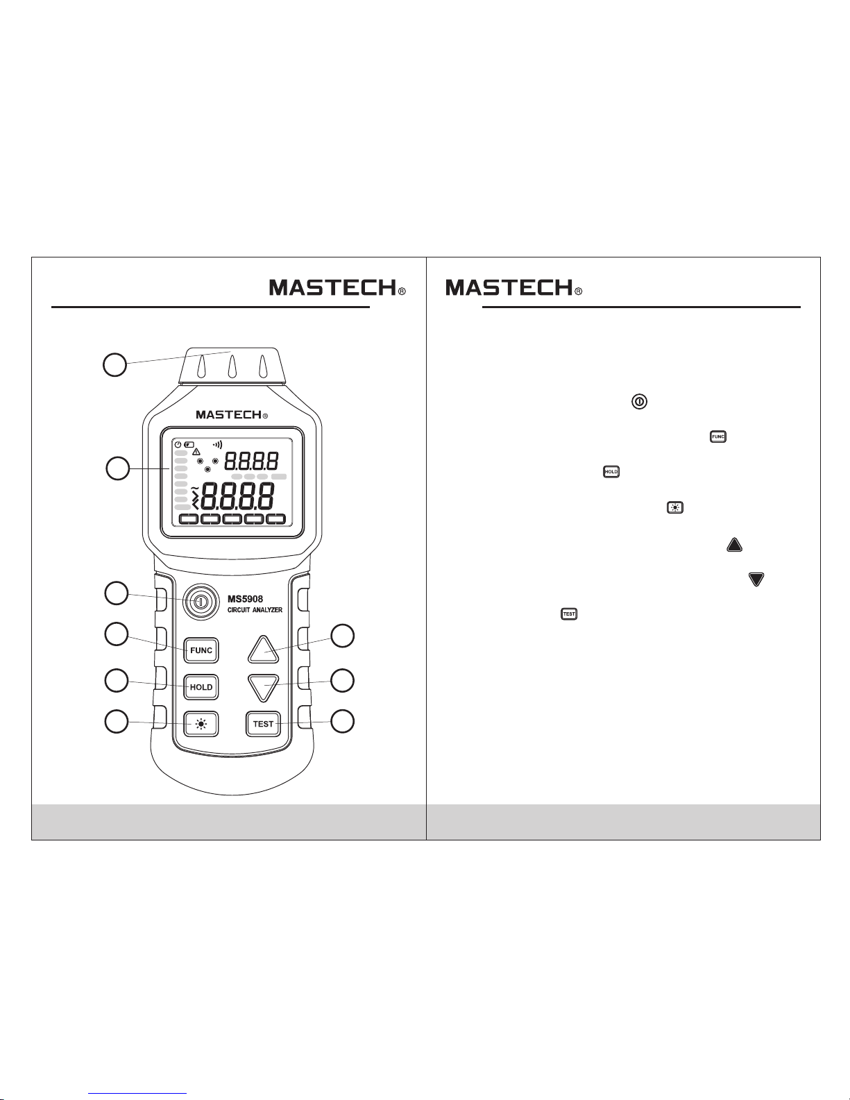
1. Input for testing
2. Display
3. Power switch key “ ”
4. Main test item selection key “ ”
5. Data hold key “ ”
6. Backlight function key “ ”
7. Sub test item up selection key “ ”
8. Sub test item down selection key “ ”
9. Test key “ ”
Ω
TEST
mA
VA
ms
Hz%
VA
ms
%
AC
L - N
L - E
N - E
Peak
Z - L
Z - N
Z - E
ASCC
12 A 15 A 20 A
HOLD
N
E
L
V Vd Z
RCD
GFCI
1
2
3
4
5
6
7
8
9
FRO N T PANE L
Page 4
05 06
L - N N - E
Peak
Volta ge (V ): eal ti me displa y of cable co nnectio n
statu s and displ ay the volt age drop of c urrent lo ad
and mea suremen t results o f phase vol tage drop
TRMS. This test i tem inclu des 3 subme nus, name ly
load wi th 12A, 15A an d 20A. Pres s Up “ ”or Down
“ ” selec tion key on t he sub test i tem to ente r the
relev ant test it em.
One ana log load ca n be added to l ive line (p hase
line) a nd zero lin e (neutra l line) for t he analys er
to meas ure the vol tage drop , and then ca lculate t he
volta ge drop of 12 A, 15A and 20A lo ad separa tely.
Under t he approp riate tes t functio n, press th e test
key “ ” to te st.
d
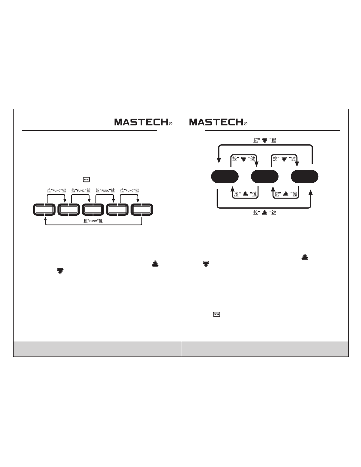
Menu Operation
The mai n test item s of the anal yser are lo cated on
the bot tom of disp lay, incl uding fiv e test item s,
namel y: voltag e (V), volt age drop (V d),
imped ance (Z), R CD and GFCI . Press the m ain test
item se lection k ey “ ” to selec t relevan t test item .
V Vd Z
RCD
GFCI
Volta ge (V): rea l time disp lay of TRMS of pha se
volta ge, wirin g status an d frequen cy. This test it em
inclu des 3 subme nus, name ly phase vo ltage (L_ N)
TRMS, v oltage to e arth of neu tral line ( zero line )
(N_E) TRMS, pea k voltage ( Peak). Pr ess Up “ ”
or Down “ ” selecti on key on the s ub test ite m to
enter t he releva nt test ite m.
Page 5
07 0 8
Z - L Z - N Z - E
ASCC
RCD: re al time dis play of lin e connect ion statu s,
and dis play curr ent RCD tri gger curr ent and tri p
time. The analy ser simul ates curr ent great er than
30mA bet ween live l ine and ear th line to te st the
perfo rmance of r esidual c urrent de vice. Pre ss the
test ke y “ ”to test.
GFCI: r eal time di splay of li ne connec tion stat us,
and dis play curr ent GFCI tr igger cur rent and tr ip
time. " GFCI" (Gr ound Faul t Circuit I nterrup ter) is
a fault l eakage pr otector t o earth. The tester
simul ates curr ent great er than 5mA be tween liv e
line an d earth lin e to test the p erforma nce of GFCI .
Press t he test key “ ” t o test.
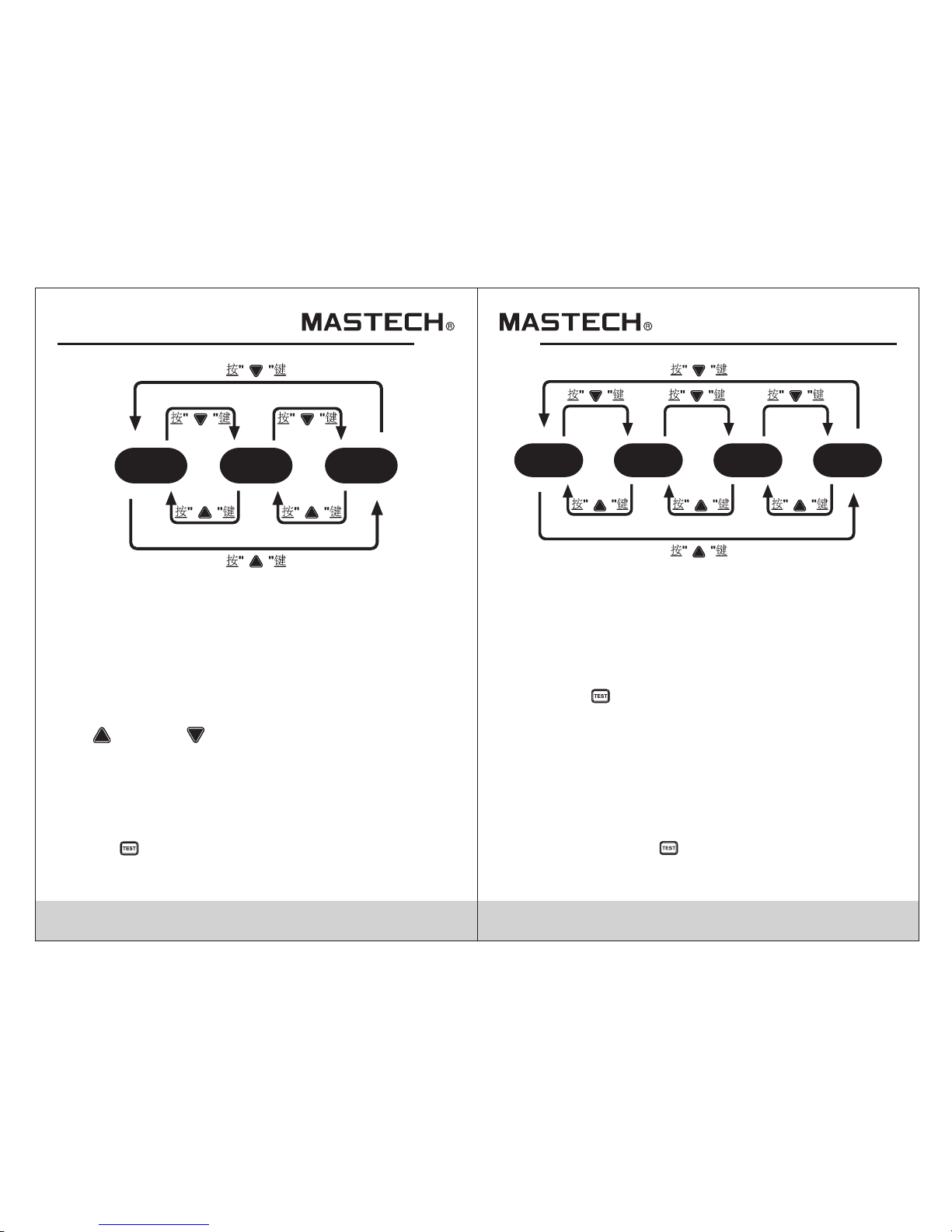
12 A 15 A 20 A
Imped ance (Z): r eal time di splay of li ne connec tion
statu s and frequ ency, and d isplay of t he impeda nce
test re sults. This test it em includ es 4 submen us,
namel y phase lin e (live lin e), condu ctor impe dance
(Z_L) , neutral l ine (zero l ine) cond uctor imp edance
(Z_N) , erath lin e conduct or impeda nce (Z_E) ,
avail able shor t-circu it curren t (ASCC). P ress Up
“ ”or Dow n “ ” selecti on key on the s ub test
item to e nter the re levant te st item.
The Ava ilable Sh ort-Cir cuit Curr ent (ASCC ) feature
can mea sure the cu rrent pas sing thro ugh break er
when th e lines are c omplete ly short- circuit ed.
Under t he approp riate tes t functio n, press th e test
key “ ” to te st.
Page 6

09 10
Other Operations:
Backl ight oper ation: in p owered st atus, pre ss “ ”
key to li ght up the ba cklight . If there is n o other key
opera tion for 30 s econds, t he backli ght will
autom aticall y turn off . You can also tu rn off the
backl ight by pre ssing the “ ” k ey.
Auto po wer off: p ress the “ ”k ey to power o n the
analy ser, the “ ” sym bol will sh ow on the dis play,
which m eans that t he auto pow er off is en abled.
If the “ ” ke y is held whi le pressi ng “ ” key to
power o n the analy ser, the “ ” sym bol will no t
show on t he displa y, which me ans that th e auto
power o ff is auto matical ly cancel led. When a uto
power o ff funct ion is enab led, if the re is no othe r
key ope ration fo r 30 minute s, the anal yser will
autom aticall y turn off .
Data ho ld functi on: press t he “ ” key to ena ble
data ho ld functi on, "HOLD " symbol wi ll show on th e
displ ay; when th e data hold f unction i s enabled ,
press t he “ ” key to dis able the da ta hold fun ction.
This fu nction is a vailabl e only for vo ltage (V)
measu rement it em, not ava ilable fo r other
measu rement it ems.
Warning
Testi ng earth li ne conduc tor imped ance, RCD
and GFC I will trig ger leaka ge protec tion devi ce
(RCD or G FCI) over t he circui t!
Sugge stion: ch eck wheth er there is i mportan t
load ov er the circ uit, then t urn off the l oad,
if nece ssary, an d retest to a void test ing error.
Page 7

11 12
Wir i ng te s t
N
E
L
The wi ring test r esult wil l be shown im mediate ly
after t he analyz er is plugg ed to the soc ket under
test. The analy zer can ide ntify the f ollowin g wiring
condi tions and d isplay th e test resu lt on the scr een.
Wirin g
condi tion
Norma l
No grou nd
wire is f ound
The liv e/zero
line is
conne cted
inver sely.
Other
condi tions
Scree n display
L E N
Capti on
Off
On
Flashing
Where a ny wiring a bnormal ity is foun d, the
analy zer can onl y complet e partial m easurem ent.
Where t here is no ea rth line, t he analyz er can only
measu re the phas e voltage a nd voltag e drop.
Notes: The analyzer can't detect
1. Circ uit volta ge, i.e. th e voltage b etween tw o live
lines ;
2. Comb ined faul t;
3. Reve rse conne ction of ea rth line an d neutral l ine.
Voltage measurement
The no rmal meas ured valu e of phase vo ltage is
120V± 10%, 60Hz . The peak v oltage of s ine-wav e
alter nating cu rrent is 1. 414 times t o the effe ctive
value o f phase vol tage. Th e voltage t o earth of
neutr al line sha ll be less th an 2V. In the sing le-phas e
circu it, if the “v oltage to e arth of zer o line” is hi gh,
it indi cates tha t the leaka ge curren t in zero lin e or
earth l ine is high . In the thre e-phase c ircuit wi th
neutr al line, a hi gh “volta ge to earth o f zero line ”
indic ates that t he three- phase loa d is imbala nced
or the ne utral lin e is affec ted by harm onic
inter ference . Excessi ve voltag e (voltag e to earth
of zero l ine) will r esult in ru nning dev iation or
inter ruption .
Warning
The max imum meas urement v oltage sh all not
excee d 265V!
Page 8

13 14
Fault l ocaliza tion and tr ouble sho oting for v oltage
probl ems
Measurement
Item
Normal
measurement
result
Fault
measurement
result
Possible
cause
Trouble
shooting
Phase voltage
108-132V
(120V)
198-242V
(220V)
The voltage
is
too high
or
too low.
The circuit is
overloaded.
Redistribute
the circuit load.
High
impedance
points are
found in
switchboard
or circuit.
Locate the
high impedance
and repair
or replace
relevant parts.
The supply
voltage
is
too high
or
too low.
Consult the
power supply
department
Voltage to
earth
of zero line
<2V >2V
Leakage
current
Find the
current source:
Is there any
multipoint
ground?
Does the
equipment
or
device
leak current?
Three-phase
imbalance
Check and
redistribute
the load
>2V<2V
Voltage to
earth
of zero line
Harmonic
interference
Increase neutral
line conductor,
install electrical
filter or use
other methods
to reduce the
harmonic
interference
The supply
voltage
is
too high
or
too low
Consult the
power supply
department
The electron
device in
the circuit
results in the
electric wave
distortion
Revaluate
and
relocate
(if necessary)
the electronic
device
in the circuit
The voltage
is
too high
or
too low.
153-185V
(120V)
280-342V
(220V)
Peak voltage
The supply
frequency
is
too high
or
too low.
Consult
the electricity
department
The frequency
is
too high
or
too low.
60Hz
(50Hz)
Frequency
Page 9

15 16
Voltage drop (V ) measurement
Dummy l oad shall b e used in the c ircuit to
measu re the load p hase volt age and the n calcula te
the vol tage drop . The volt age drop an d load phas e
volta ge will be di splayed w hen the loa d reaches
12A, 15 A and 20A.
In term s of qualif ied circu it, when me asureme nt
is made i n the most re mote sock et from the
switc hboard, t he voltag e drop shal l be less tha n 5%.
Durin g the measu rement of t he remain ing socke ts
of the sa me area, th e farthes t socket fr om the
switc hboard sh all be meas ured firs t and then ot her
measu rements s hall be mad e from the di stant to
the nea r. The read ing of the vo ltage dro p shall be
shown o n the downw ard trend .
If the vo ltage dro p exceeds 5 % and no obvi ous
drop of r eading is f ound duri ng the meas urement
made ne ar the swit chboard , it indica tes that th e
first c onnecti on point go es wrong. I n this case ,
perfo rm a visual i nspecti on of the wir e connect ion
among t he first co nnectio n point, eq uipment a nd
switc hboard an d the conne ction of br eaker
(air- break swi tch). Usu ally, a hig h impedan ce point
gener ates heat . To locate th is proble m, infrar ed
radia tion ther mometer c an be used. I n additio n, we
can dir ectly mea sure the vo ltage on bo th sides of
the bre aker (air -break sw itch) to lo cate the po int of
failu re.
d
If the vo ltage dro p exceeds 5 %, and duri ng the
measu rement ma de near the s witchbo ard, the
readi ng drops co nstantl y and no obvi ous chang e
is foun d between t he two sock ets, it ind icates th at
the lea d wire diam eter is too s mall comp ared with
the tra nsmissi on distan ce, the tra nsmissi on
dista nce is too lo ng or the cir cuit is ove rloaded .
Under s uch circu mstance s, check th e cable to se e
if the le ad wire dia meter com plies wit h the requi red
stand ard, and me asure the l ead wire cu rrent to se e
if it is ov erloade d.
If the vo ltage dro p exceeds 5 % and there i s an
obvio us change o f voltage d rop readi ng betwee n
the two s ockets, i t indicat es that a hig h impedan ce
point e xists bet ween the tw o sockets . Usually,
probl ems are fou nd at the con tact, suc h as poor
conne ction, lo ose conne ctor, or soc ket probl em.
Page 10

17 1 8
Fault localization and trouble shooting for voltage drop
Measurement
Item
Normal
measurement
result
Fault
measurement
result
Possible
cause
Trouble
shooting
Voltage drop
The
voltage drop
is
too high.
Redistribute
the circuit load
The circuit is
overloaded.
Rearrange
the wire in
compliance
with the
relevant
standard.
High
impedance
point exists
between the
circuit and
switchboard.
Repair or
replace the
parts
generating
high
impedance
<5%
Compared
with power
transmission
length,
the wire
is small.
Cable impedance (Z) measurement
If the vo ltage dro p exceeds 5 %, analys is on the
imped ance of liv e line and ze ro line sha ll be made.
If one da tum is obvi ously lar ger than th e other, it
indic ates that t he high imp edance co nductor g oes
wrong . Under the se circum stances , check all t he
condu ctor conn ection be hind the sw itchboa rd. If
imped ances are a ll high, th is indica tes that th e lead
wire di ameter is t oo small fo r the power t ransmis sion
lengt h or the qual ity of equi pment, pa rts or
conne ctor is poo r.
Usual ly, the ear th line imp edance is l ess than 1Ω
to prov ide a free di scharge r oute for fa ilure cur rent.
Accor ding to IEE E, the eart h line impe dance sha ll
be less t han 0.25Ω t o ensure th e earthin g conduct or
to disc harge the f ailure cu rrent whi ch threat ens all
the equ ipment. The surge s uppress ion syste m shall
be grou nded reli ably to pro tect the eq uipment w hen
this sy stem suffers tran sient ove rvoltag e.
ASCC is th e data calc ulated ba sed on this f ormula:
phase v oltage/ line impe dance (Li ve line + zer o line):
ASCC= Ph ase volta ge/
(Live l ine imped ance + Zero l ine imped ance)
Notes:
1. As the te st of earth l ine imped ance will t rigger
the res idual cur rent devi ce due to tes t princip le,
simil ar device s hall be rem oved from t he circui t
befor e testing .
2. Chec k the circu it to see if th ere is heav y load
over th e circuit b efore tes ting and, i f necessa ry,
turn off the load t o avoid wro ng test res ult.
3. Eart h connect ion is requ ired when t he cable
imped ance is tes ted in the 2- wire syst em
(with out earth l ine).
Page 11

19 2 0
Fault localization and trouble shooting
Measurement
Item
Normal
measurement
result
Fault
measurement
result
Possible
cause
Trouble
shooting
Conductor
impedance
for
live line
and
zero line
The
impedance
is
too high
Redistribute
the
circuit load.
The circuit
is overloaded.
Check the
wire diameter
and
rearrange
the wire
accordingly.
High
impedance
point exists in
the circuit
or
switchboard.
Locate the
high
impedance
and repair
or replace
the parts
The wire
diameter is
too small
for the power
transmission
length.
Check
the wire
diameter and
rearrange
the wire
accordingly.
Locate
the high
impedance
and repair
or replace
the parts
The wire
diameter is
too small
for the power
transmission
length.
High
impedance
point exists
in the circuit
or
switchboard.
The
impedance
is
too high
Conductor
impedance
for
earth line
For
personnel
safety
<1Ω
For
equipment
safety
<0.25Ω
No. 14 line
(2.0mm )
<0.15Ω/m
No. 12 line
(3.3mm )
<0.1Ω/m
No. 10 line
(5.2mm )
<0.03Ω/m
Residual current device (RCD) test
Durin g the RCD tes t, the anal yzer will g enerate a
low cur rent betw een live li ne and eart h line by
means o f a fixed res istance , which wil l affect t he
curre nt balanc e between l ive line an d zero line .
Accor ding to UL, t his curre nt trigge r shall be le ss
than 30 mA. The RC D shall res ponse to th e current
imbal ance by cut ting off t he power. The ana lyzer
will di splay the v alue of the c urrent tr iggered ( mA)
and res ponse tim e (ms).
The wor d “TEST” wi ll be displ ayed when t he button
“ ” is pres sed, whic h means the t est is in the
proce ss. RCD sha ll be trigg ered with in the spec ified
index t o cut off th e power of th e circuit u nder test .
If the RC D fails to be t riggere d, the anal yzer will
stop te sting aut omatica lly after 6 .5 second s.
Analy sis on RCD sh all be made a ccordin g to the
test re sult to see i f it goes wro ng, is inst alled
prope rly or prot ects the ci rcuit effective ly.
Notes:
1. Chec k the circu it to see if th ere is heav y load over
the cir cuit befo re testin g and, if nec essary, turn
off th e load to avo id wrong te st result .
2. Eart h connect ion is requ ired when t he RCD is
teste d in the 2-wi re system ( without e arth line ). .
2
2
2
Page 12

21 2 2
Fault localization and trouble shooting
Measurement
Item
Normal
measurement
result
Fault
measurement
result
Possible
cause
Trouble
shooting
Check the
circuit and
install
the RCD
according
to the
manufacture
requirement
and
relevant
standard
The RCD
is
installed
improperly
Fail to be
triggered
within
the
specified time
RCD
is triggered
within the
specified
time
RCD test
RCD goes
wrong
Repair or
replace RCD
Fail to
be triggered
(Invalid test)
Triggering time formula specified by UL: T = (20/I)
1.43
T: Triggering time (Unit: second)
I: Triggering current (Unit: mA)
GFCI test
During the GFCI test, the analyzer will generate a low
current between live line and earth line by means of a
fixed resistance, which will affect the current balance
between live line and zero line. The GFCI shall response
to the current imbalance by cutting off the power. The
analyzer will display the value of the current triggered
(mA) and response time (ms).
The word “TEST” will be displayed when the “ ” key
is pressed, which means the test is in the process.
GFCI shall be triggered within the specified index to cut
off the power of the circuit under test. If the GFCI fails to
be triggered, the analyzer will stop testing automatically
after 6.5 seconds. Analysis on GFCI shall be made
according to the test result to see if it goes wrong, is
installed properly or protects the circuit effectively.
Notes:
1. Chec k the circu it to see if th ere is heav y load
over th e circuit b efore tes ting, if ne cessary, turn
off th e load to avo id wrong te st result .
2. Eart h connect ion is requ ired when t he GFCI is
teste d in the 2-wi re system ( without e arth line ).
Page 13

23 24
Fault localization and trouble shooting
Measurement
Item
Normal
measurement
result
Fault
measurement
result
Possible
cause
Trouble
shooting
Check the
circuit and
Install the
GFCI
according
to the
manufacture
requirement
and r
elevant
standard
The GFCI
is
installed
improperly
Fail to be
triggered
within
the
specified time
GFCI
is
triggered
within
the
specified
time
GFCI test
GFCI goes
wrong
Repair or
replace GFCI
Fail to
be triggered
(Invalid test)
General technical index
Displ ay: LCD
Overl oad: “OL” o r “>”
Low bat tery volt age: “ ”
Time for au to power- off: Pow er off whe n the keys
aren' t pressed f or 30 minut es.
Humid ity: <80% R elative h umidity ( 0°C~50° C)
Stora ge temper ature: 0° C~50°C <8 0%
Relative h umidity
Physi cal dimen sion: 193 mm (L)×78 mm(W)×3 8mm(D)
Power s ource: Si x AAA batteri es
Weig ht: 295g (i ncludin g batteri es)
Accuracy index
Accuracy: ±(% reading + words), one-year guarantee.
Reference conditions:
Ambient temperature: 18°C-28°C
Relative humidity: no more than 80%
AC conversion is measured with true RMS
Measurement item Range Resolution Accuracy
Phase voltage 85.0-265.0V Resolution ±(1.0%+ 0.2V)
Peak voltage
Frequency
Voltage drop
Load voltage
Voltage to earth
of zero line
Impedance for
live line, zero line
and earth line
RCD triggering time
RCD
triggering current
GFCI triggering time
GFCI
triggering current
121.0-374.0V
45.0~65.0Hz
0.1%~99.9%
10.0~265.0V
0.0~10.0V
0.00~3.00Ω
1ms~6.500s
30mA~37mA
1ms~6.500s
6mA~9mA
>3.00Ω
0.1V
0.1V
0.1Hz
0.1%
0.1V
0.01Ω
1ms
0.1mA
1ms
0.1mA
±(1.0%+ 0.2V)
±(1.0%+ 0.2Hz)
±(2.5%+ 0.2%)
±(2.5%+ 0.2V)
±(2.5%+ 0.2V)
±(2.5%+ 0.02Ω)
No ensure the accuracy
±(1.0%+ 2ms)
±(1.0%+ 0.2mA)
±(1.0%+ 2ms)
±(1.0%+ 0.2mA)
Page 14

25
HYS006690
1) The analyzer is powered by six AAA batteries.
2) Cut off the power and pull out the test line.
3) Unscrew the battery compartment and open the cover.
4) Replace the batteries.
5) Ensure the batteries are installed properly
(Do not mismatch polarity)
6) Put back the cover and tighten the screws.
Maintenance
Batte ry instal lation an d replace ment:
Clean ing:
Use soft cloth and neutral cleanser to clean the housing.
Use of abrasive or organic solvent is not allowed.
 Loading...