

Page 1
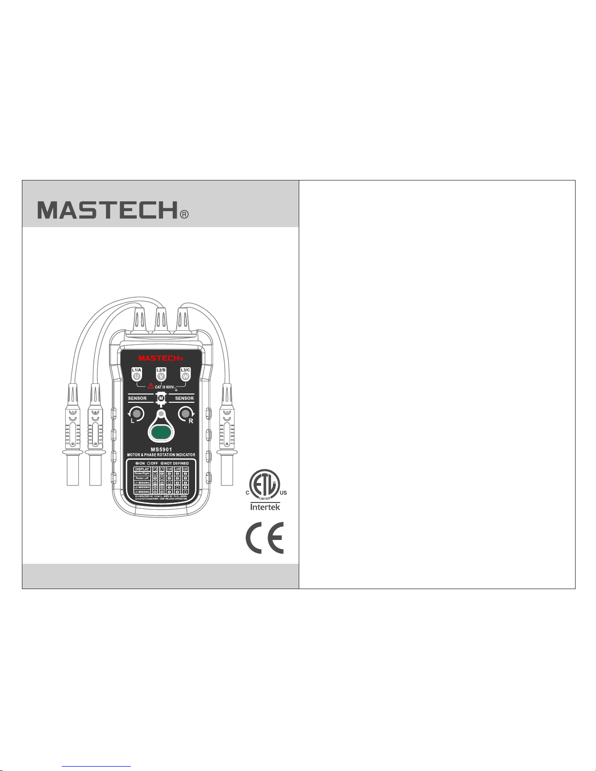
MS5901
Three Phase Rotation Indicator
Users Manual
ON
1KV/ 10A CAT III
1KV/ 10A CAT III
1KV/ 10A CAT III
Page 2

Introdution....................................................1
CONTENTS CONTENTS
1. Symbols.................................................4
List of Figures
Accessories..................................................1
Safety Information........................................2
Symbols.......................................................4
Elements Of The Apparatus...........................5
Using the Motor &
Phase Rotation Indicator...........................6
Determine Rotary Field Dir ect ion ... ... ... ......6
Non-Contact Rotary Field Indication...........8
Determine The Motor Connection.............10
Magnetic Field Detection.........................11
Maintaining The Apparatus..... ... ... ... ... ... ..11
Cleaning................................................12
Replacing And Disposin g
Of The Batteries.....................................12
Specifications..................... ... ... ... ... ... ... .14
2. Reliable Motor
Test Requirements................................10
1. Motor And Phase
Rotation Indicator....................................4
2. Phase Indication Table............................7
3. Motor Rotation........................................9
4. Battery Replacement ............................13
List of Tables
Page 3
01 02
Introduction
Moto r and Pha se Rota tion In dicat or is a han dheld ,
batt ery-o perat ed inst rumen t desig ned to de tect
the ro tary fi eld of th ree-p hase sy stems a nd
dete rmine m otor- rotat ion dir ectio n.
Prot ectio n provi ded by th e instr ument w ill be
impa ired if u sed in a ma nner no t speci fied by t he
manu factu rer.
Motor and Pha se Rota tion In dicat or ship s with th e
following i tems:
• 3 test p robes
• 3 alligator c lips
• 9 V batt ery
• Users Manua l
If an it em is dam aged or m issin g, cont act the p lace
of purchase i mmedi ately.
Accessories
Safety Information
• Read the foll owing s afety i nform ation c arefu lly
befo re usin g or serv icing t he inst rumen t.
• Adhere to loc al and na tiona l safet y codes .
• Individua l prote ctive e quipm ent mus t be used t o
prev ent sho ck and in jury
• Use of instru ment in a m anner n ot spec ified b y
the ma nufac turer m ay impa ir safe ty
feat ures/ prote ction p rovid ed by the e quipm ent.
• Avoid working a lone.
• Insp ect the t est lea ds for da maged i nsula tion or
expo sed met al. Che ck test l ead con tinui ty.
Dama ge lead s must be r eplac ed. Do no t use the
apparatus i f it look s damag ed.
identifie s condi tions a nd acti ons tha t may
damage the ap parat us.
CAUTION
identifie s condi tions a nd acti ons tha t pose
hazard(s) t o the use r.
WARNING
Safety Info rmati on To avoid possible
electric sh ock or fi re, do th e follo wing:
Read First
Page 4

03 04
Symbols
• Be car eful wh en work ing abo ve 30 V ac rm s, 42 V
ac pea k and 60 V dc . Such vo ltage s pose a sh ock
haza rd.
• When u sing th e probe s, keep f inger s away fr om
prob e conta cts. Ke ep fing ers beh ind the f inger
guar ds on the p robes .
• Measureme nts can b e adver sely affe cted by
impe dance s of addi tiona l opera ting ci rcuit s
conn ected i n paral lel or by t ransi ent cur rents .
• Verify opera tion on a k nown so urce pr ior to
meas uring h azard ous vol tages ( volta ges abo ve
30 V ac rm s, 42 V ac pe ak and 60 V d c).
• Do not use the ap parat us with a ny of the p arts
remo ved.
• Do not use the ap parat us arou nd expl osive g as,
vapo r, or dust .
• Disconnec t the tes t leads f rom pow er sour ces and
the ap parat us befo re chan ging th e batte ry.
• Do not use the ap parat us in a wet e nviro nment .
The followi ng symb ols app ear on th e Motor a nd
Phase Rotat ion Ind icato r or in thi s manua l.
Table 1. Sy mbols
Caution, ri sk of dan ger
Earth(gro und) TE RM IN AL
European un ion dir ectiv es
Equipment p rotec ted
throughou t by DOUB LE
INSULATION or
REINFORCE D INSUL ATI ON
Alternati ng curr ent
Direct curr ent
CONFORMS TO UL STD
61010-1,6 1010- 2-030 ,
CERTIFIED TO C SA STD
C22.2 No.61 010-1 ,
61010-2-0 30
Page 5

1KV/1 0A CAT III
1KV/1 0A CAT III
1KV/1 0A CAT III
Page 6

07 08
WARNI NG
if the n eutra l condu ctor, N, i s conne cted instead
of L1, L 2, or L3. R efer to F igure 2 ( also sh own on
the fa ce of the a ppara tus) fo r more in forma tion.
Figu re 2. Pha se Indi catio n Tab le (shown on the
face of the app aratu s)
Non-Contact Rotary Field Indication
For non-con tact ro tary fi eld ind icati on:
1. Disconne ct all te st prob es or all igato r clips f rom the
appa ratus .
2. Pos ition t he Indi cator o n the mot or so tha t it is
para llel to t he leng th of the m otor sh aft. The
Indi cator s hould b e one inc h or clos er to the m otor.
See Fi gure 3.
The rotary in dicat or ligh ts
Note
The Indi cator w ill not o perat e with en gines
controlle d by freq uency c onver ters. The b ottom of
the apparat us shou ld be ori ented t oward s the dri ve
shaft. See th e Orien tatio n Symbo l on the ap paratus.
Figu re 3. Mot or Rota tion
See Table 2 for the min imum mo tor dia meter a nd
number of pol e pair to o btain a r eliab le test r esult .
3. Pre ss the ON /OFF bu tton. The g reen ON i ndica tor
show s that th e instr ument i s ready f or test ing.
Eith er the Cl ockwi se or Cou nter Cl ockwi se Rota ry
indi cator i llumi nates s howin g the typ e of rota ry
fiel d direc tion pr esent .
Page 7

09 10
Table 2. Reliable Motor Test Requirements
Determine the Motor Connection
1. Connect th e allig ator cl ips to th e other e nd of
the te st lead s.
2. Connect th e allig ator cl ips to th e motor
conn ectio ns, L1 to U , L2 to V, L3 t o W.
3. Press the ON /OFF bu tton. The g reen ON i ndica tor
show s that th e instr ument i s ready f or test ing.
4. Turn the moto r shaft h alf a rev oluti on towa rds
the ri ght.
Note
The bottom of t he appa ratus s hould b e orien ted
towards the d rive sh aft . See t he Orie ntati on
Symbol on the a ppara tus.
Either the Cl ockwi se or Cou nter Cl ockwi se Rota ry
indicator i llumi nates s howin g the typ e of rota ry
field direc tion pr esent .
Page 8

11 12
Magnetic Field Detection
To detect a magne tic fie ld, pla ce the ap parat us to
a solenoid va lve. A magnetic field is present if
either the Cl ockwi se or the C ounte r Clock wise
Rotary indi cator i llumi nate.
Maintaining The Apparatus
This sectio n provi des bas ic main tenan ce
informati on.
To avoid da magin g the app aratu s:
• Do not a ttemp t to repa ir or ser vice th e
appa ratus u nless q ualif ied to do s o.
• Make sure tha t the rel evant c alibr ation ,
performan ce test , and ser vice in forma tion
is bei ng used .
Caution
Cleaning
Periodica lly wip e the cas e with a da mp clot h and
mild deterg ent. Cl ean onl y with so ap and wa ter and
remove any re sidue a fterw ards.
Caution
To avoid da magin g the app aratu s:
• Do not u se abra sives o r solve nts. Abrasi ves
or sol vents w ill dam age the a ppara tus case.
• Prior to clea ning, r emove t est lea ds from t he
appa ratus .
Replacing And Disposing Of The Batteries
Warning
To avoid el ectri c shock , disco nnect t he test
leads from th e sourc e befor e openi ng the
apparatus f or batt ery rep lacem ent.
Note
The apparat us cont ains al kalin e batte ries. D o not
dispose of th ese bat terie s with ot her sol id wast e.
Used batter ies sho uld be di spose d of by a qua lifie d
recycler or h azard ous mat erial s handl er.
Page 9

13 14
The apparat us uses a 9 V b atter y (supp lied) .
To replace the ba ttery, fol low the se step s and ref er
to Figure 4:
1. Disconne ct test l eads fr om any po wer sou rce.
2. Place the ap parat us face d own on a no nabra sive
surf ace and l oosen t he batt ery-d oor scr ew with
a scre wdriv er.
3. Lift the bat tery ac cess li d away fr om the ap paratus.
4. Replace th e batte ry as sho wn in Fig ure 4.
Obse rve the b atter y polar ity sho wn in the b attery
comp artme nt.
5. Secure the b atter y acces s lid bac k in posi tion
with t he scre w.
6. Place the ap parat us back i n the hol ster.
Figu re 4. Bat tery Re place ment
Environme ntal
Operating Temp eratu re
0 °C to +4 0 °C
Operating Altit ude
2000 m
Poll ution D egree
2
Mechanica l
Specifica tions
131 x 72 x 30 mm
(5.2 x 2.8 x 1.2 in )
Weight
approx 252 g (0 .6 lbs)
Humidity
15 % to 80 %
Safety Spec ifica tions
Electrica l Safet y
Meets DIN VDE 0 411
IEC 61010 DIN
VDE 0413-7
EN 61557-7
IEC 61557-7
Maximum Ope ratin g
Voltage ( Ume)
400 V AC for
all ranges
Protectio n Level
CAT III 600 V
Page 10

15
00-05-4099
Electrica l Speci ficat ions
Battery
6F22/9V
Current Con sumpt ion
max 20 mA
Battery Lif e
minimum 1 yea r for
average use
Determine R otary F ield Di recti on
Nominal Voltag e
Rotary Dire ction
1 to 400 V AC
Nominal Voltag e
Phase Indic ation
120 to 400 V AC
Frequency R ange (f n)
2 to 400 Hz
Test Curr ents
(In pe r phase )
less than 3.5 m A
Non-Conta ct Rota ry Fiel d Indic ation
Frequency R ange (f n) 2 to 400 Hz
Determine t he Moto r Conne ction
Nominal Test Voltag e
(Ume)
1 to 400 V AC
Nominal Test Cur rents
(In pe r phase )
less than 3.5 m A
Frequency R ange (f n) 2 to 400 Hz
DONGGUAN HUAYI MASTECH COMPANY LIMITED
Yuliangwei Industrial Area,Qingxi
Dongguan,Guangdong,China
http://www.p-mastech.com
 Loading...