

Page 1

MS2301
USERS MANUAL
EARTH RESISTANCE CLAMP
Page 2

CONTENTS CONTENTS
WARNING
MAINTENANCE
INTRODUCTION
FRATURES
SUMMARY OF FUNCTION
LAYOUT
LCD DISPLAY
OPERATION
ON/OFF OPERATION
EARTH RESISTANCE
MEASUREMENT
CURRENT MEASUREMENT
HOLD BUTTON
ALARM OPERATION
MEMORY FUNCTION
SPECIAL FUNCTION
SPECIFICATION
FEATURES
ACCESSORY
CHANGING THE BATTERIES
CHARGE THE BATTERIES
APPLICATION FIELD
.....................................................1
............................................1
...........................................2
...................................................2
............................3
........................................................3
...............................................4
...............................6
......................................7
.......................10
...........................................11
...................................11
..................................12
...................................13
..........................................15
..................................................15
...............................................16
......................16
..........................17
..................................18
Page 3
Page 4
1
03 04
Summary of function
FUNCTION
BUTTON
A MEASUREMENT/
A LARM VALUE INCREASE/
RECORD NUMBER SELECT
ON/OFF/EXIT SET MODE
Ω MEASUREMENT/
A LARM VALUE MINISH /
RECORD NUMBER SELECT
HOLD DISPLAY
SELECTA LARM MODE
SELECT /SET MEMORY MODE
SWITCH BUZZER ON/OFF
SET A LARM VALUE
AUTO POWER OFF FUNCTION SET
READ SAVED MEASUREMENT VALUE
RESET MEMORY T O ZERO HOLD+MEM
HOLD
A L
MEM
▲A
▼
Ω
+MEM
+HOLD
Ω
A L
LCD Display
(Not e: when s witch o n, the clamp perfo rms a rap id
auto -test o f the whole display. All t he symb ol on the
LCD ar e displ ay for th is short time.)
6
7
8
9
L
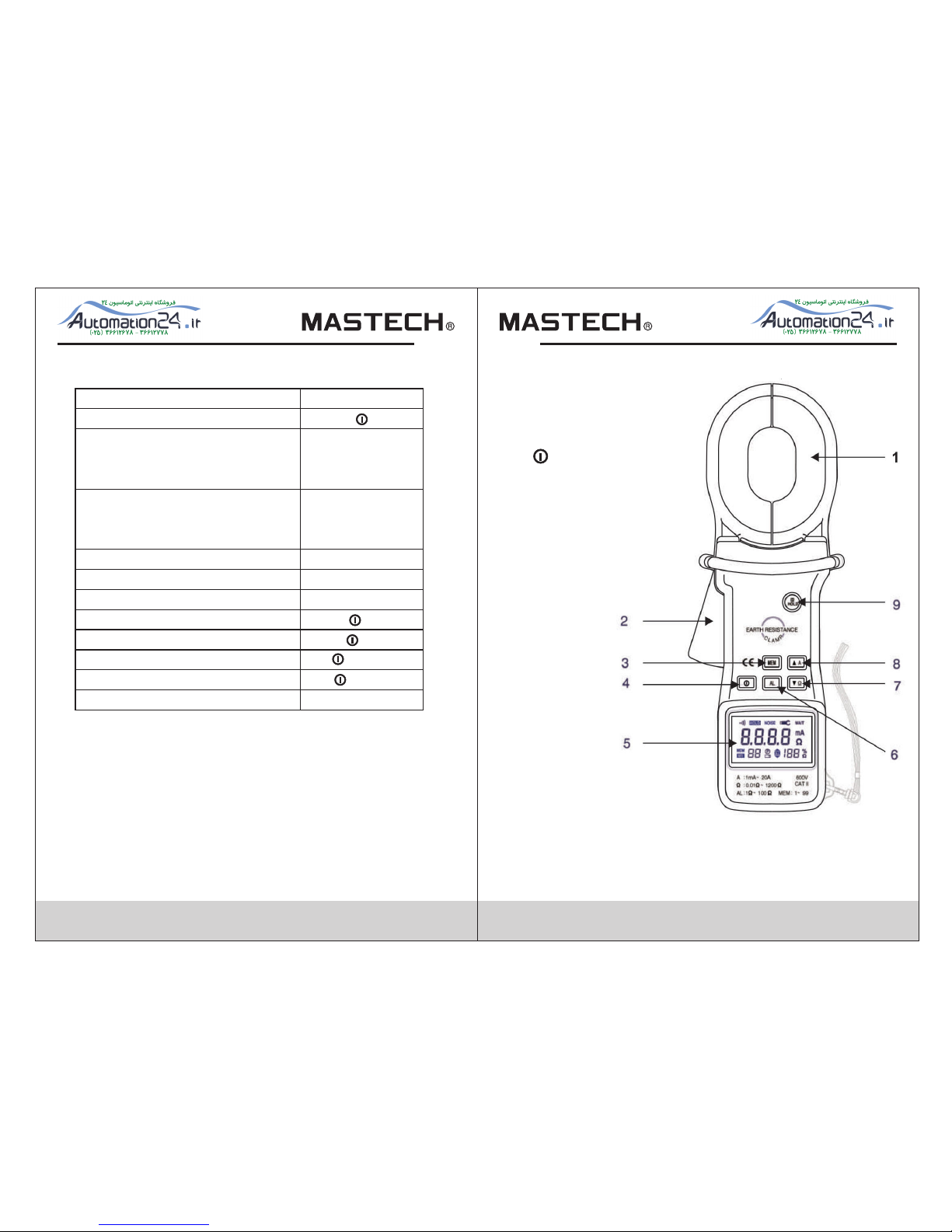
ayout
1
. C
lam
p j
a
w
2. Tri
gg
e
r
3
. ME M B
utto
n
4. B
utto
n
(
ON/O
FF BUTTON
)
5
. LCD Di
s
p
l
a
y
6
. AL B
utto
n
7. ▼Ω B
utto
n
8
. ▲A B
utto
n
9
. HOLD B
utto
n
Page 5
05 06
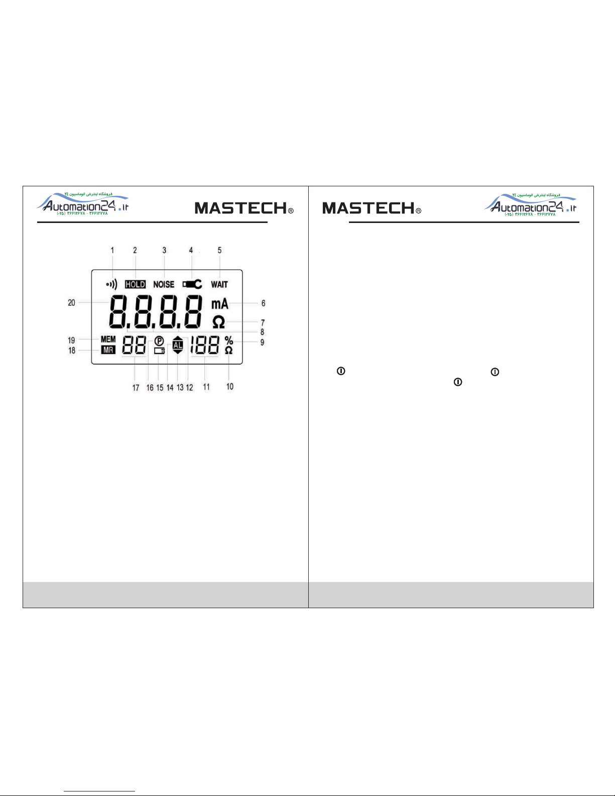
1. Buz zer ON sy mbol
2. HOL D symbo l : hold the last measureme nt
3. Int erfer ence Symbol : showing tha t the cur rent in
the lo op is dis turbed such that the resi stanc e
meas ureme nt value is not be guarante ed.
4. Cla mp symb ol : show ing that the clamp i s close d
inco rrect ly, can not measure.
5. Wait symb ol : show ing that the instr ument i s
auto -cali brating
6. Cur rent me asure ment unit
7. Res istan ce meas urement unit
8. Dec imal po ints
9. Per cent si gn of the batteries actua l servi ce life
10. Ala rm thre shold v alue of resistan ce unit
11. Digita l displ ay of the battery ac tual se rvice l ife or
Alarm t hresh old value
12. H igh Alar m symbo l
13. Lo w Alarm sy mbol
14. Ala rm mode s ymbol
15. L ow volt age ind ication symbol
16. Au to Powe r Off symbol
17. R ecord n umber s ymbol
18. R ead mem ory mod e symbol
19. s ave in me mory mode symbol
20. 4 d igit LC D digit al display
Operation
1. ON/OFF Operation
butt on swit ches ON/OFF. Press button s o the
clam pswitc h on, Pre ss the button for 2 se conds ,
the in strum ent swi tch off.
As soo n as it swi tch on, the earth resista nce cla mp
begi ns to aut o-cal ibrate to obtain b atter r esolution.
When i t is cali brati ng, the instrume nt will c ount from
CAL 9 to CAL 0. The u ser mus t wait for the clamp
comp leted c alibr ation. Do not open t he clam p or hook
the cl amp jaw a round t he conductor or th e objec t be
meas ured in c ase of th e calibration. Af ter the c alibration
comp leted , the ins trument return s the mea surement
mode w hen las t switc h off. If the ins trume nt is in
resi stanc e measu rement mode when s witch o ff , the
LCD wi ll disp lay the p rimary resista nce mea sured value.
Page 6

• Buzzer ON
• Aloop earth resistance of 36.2Ω
• The batteries service life is 87%
07 08
2.Earth resistance measurement
1. After switching on, the instrument is automatism in
measurement current mode, you can press the▼Ω
button to configure for resistance measurement mode.
2. Hook the clamp jaw around earth leads or electrode
to be tested.
3. If symbol “ - - - ” and symbol are shown on the
display, it indicates that the clamp is closed incompletely.
You must press the trigger of the instrument several
times to close the clamp jaw correctly. After the
symbol disappears from the display, then it is in the
normal measurement mode.
4. Read the measurement value on the display.
5. When the display appears the “NOISE” symbol, it
indicates that there is an interference current in the
loop, the resistance measurement is not assured.
6. Schematic of measurement
• Buzzer ON
• A loop earth resistance of 68.7Ω
• The earth resistance value is above the high
alarm threshold 50Ω, a beep is emitted
• Buzzer ON
• A loop earth resistance of 0.5Ω
• The earth resistance value is less than the low
alarm threshold value 8Ω, a beep is emitted
Page 7

09 10
• Buzzer ON
• Read the 22th recorded measurement, the loop
earth resistance of 176.4Ω
• The low alarm threshold of earth resistance set at 15Ω
• Buzzer ON
• A interfered current is in the loop resistance, the
current measured resistance is 55.2Ω, the value
is not guaranteed
• The batteries service life is 86%
• Buzzer ON
• A loop earth resistance of 93.7Ω
• The batteries service life is 18% and less than 20%.The
display appears the low voltage indication
• Auto Power Off function is valid
• 55 recorded values in the memory
• Buzzer ON
• A loop earth resistance of 19.6Ω
• The earth resistance value is less than the high
alarm threshold value 30Ω, no beep is emitted
• 6 recorded values in the memory
Page 8

11 12
• The clamp jaw is closed incorrectly, ”---” is displayed
• The batteries service life is 90%
3. Current measurement
1. Press the A button on the instrument.
2. The display shows the current unit “A” or “mA”, the
instrument is in
current measurement mode. You can measure current
of the conductor.
3. Read the measurement value on the display.
4. If the display shows symbol “OL” , it indicates the
measured value exceeds the measurement range.
4. Hold button
Press the HOLD button to lock display of the current measure
state and last measurement on measurement mode.
5. Alarm operation
1. On resistance measurement, press the AL button, “AL”
symbol and the value of the alarm threshold are displayed.
2. According to the measurement demand, you can press
“AL” button time after time to select one of three alarm
modes:
---- LOW ALARM MODE: when signals
measurement below the alarm threshold, a continuous
beep at low frequency.
The symbol is displayed.
---- HIGH ALARM MODE: when signals measurement
belowthe alarm threshold, a continuous beep at high
frequency.The symbol is displayed.
---- NO ALARM MODE: signals measurement is not
confined in alarm threshold .
3. Set the alarm threshold
The earth resistance clamp set initial Alarm threshold value
is high alarm threshold of 20Ω. In resistance measurement
mode, press the +Al to set in Alarm threshold value
setting mode, then “AL” symbol and the Alarm threshold
value are displayed; press A or Ω button,you can
increase or decrease the Alarm threshold value, the Alarm
threshold is from 1 to 100Ωinclusive. After switching off the
threshold value is not changed. Setting Alarm threshold
value completed, you can press AL button to select one of
the three Alarm mode: HIGHT ALARM MODE, LOW
ALARM MODE, NO ALARM MODE, when the selection is
completed, you can press the button to exit Alarm
threshold value setting mode.
Page 9

13 14
6. Memory function
1. Clear memory
Press the HOLD+MEM for 3 seconds, then the “CLR”
symbol is shown on the display. At a beep, the memory
is cleared. The instrument return to measurement mode
automatically.
2. Save measured value
When press the MEM button,the ”MEM” symbol is
displayed; press this button for 2 seconds to save the
current measured value in memory.The number of record
goes up by 1 automatically and is shown on the display,
when the number of the record is 99, if MEM button is
pressed again at this time, a beep is emitted and the
instrument prohibits saving the measurement value.
When the batteries service life is less than 20%, a beep
warns that the saving measured value is prohibited.
3. Read the saving measurements
Press the +MEM for 1 second, then the instrument is
in the read memory mode, the “MR” and “HOLD” symbo
are displayed, the number of the record and the measured
value are shown at one time. To display previous record
or subsequent record in the memory press A button
or Ω button. You can press the button to exit read the
record mode to return resistance measurement mode.
7. Special function
1. Press +Ω button, the buzzer symbol disappears
from the display, the buzzer be switched off and beep
function of pressing button or Alarm function is invalid;
press the +Ω to switch on the buzzer again.
2. ON/OFF Auto Power Off function
Press +HOLD button, the LCD display “P” symbol,
the Auto Power Off function switch on. After no operation
for 5 minutes, the instrument switch off automatically.
Press +HOLD again, then the “P” symbol disappears
from the display, the Auto Power Off function switch off.
To switch off the instrument press the button for 2 seconds.
3. Symbol
When the battery service life is less than 20%,the symbol
is continual displayed, the clamp can not save the measured
value in memory in this case. When the batteries service life
is less than 15%, prompt beeps is continual emitted. After
10 beeps is emitted, the instrument switch off automatically.
4. NOISE Symbol
“NOISE” appears on the display indicate that an interference
current of testing earth resistance is too high, the resistance
measurement is not accurate.
5. Symbol
This symbol indicates that the clamp is close incorrectly
and can not make a measurement.
6. WAIT Symbol
This symbol is shown on the display when the instrument
switch on and begin to auto-calibrate., it is from CAL 9 to
CAL 1 to calibration count.
7. OL Symbol
Measured resistance value exceeds 1200Ωor measured
current value exceeds 20A, this symbol is shown on the
display.
Page 10

Page 11

17 18
1. Switch off
2. Unscrew the screw on the battery cover
3. Remove the cover
4. Take the battery box out of the instrument
5. Replace new batteries of the same type
7. Reinstall the battery box
8. Replace the battery cover
9. Reinstall the screw
Charge the batteries
Refer to the operation manual on the battery charger.
Application field
EARTH RESISTANCE CLAMP is designed for testing earth
resistance of any loop system, for example no only earth
resistance of electric power transportation conductors and
communication circuitry, but also earth resistance of electric
equipment and lightning arrester can be tested. When there
is a interference current in the grounding loop, the accuracy
of resistance measurement is affected, the interference
current can be tested by the earth resistance clamp.
Principle of mearsurement
Rx : earth resistance value to be tested
R1R2…Rn: multiple parallel earth resistance
Rearth: normally be regard as 0Ω
Rguard wire : normally be regard as 0Ω
RLoop=Rx+Rearth+(R1// R2//…Rn)+Rguard wire
When R1//R2//…Rn<<Rx, then RLoop=Rx
Page 12

19 20
1. Test ing e art h resistance of electric power
1.) Testing Earth Resistance Of Distribution
Circuitry
Usually most electrodes of neutral wire are connected
in parallel for three-phase, four-wire system. The
resistance is very low, so you only hook the clamp
around earth conductor to be measured to test the
distribution circuitry.Other earth electrodes become
supplementary electrode naturally.
2.) Testing Transmit Electricity Circuitry (Iron Tower)
Transmit electricity circuitry works by iron tower.The
earth system of iron tower connect with lightning rod
of iron tower, so iron tower that needn't tested becomes
very well supplementary electrode. This is a great
progress that is breakthrough from traditional tester
which throwed into supplementary electrode on the
road.
2. Electric power maintain of the factory
Usually the factory is divide into several different earth
network fields, so you can test earth resistance in this way:
3. Testing earth resistance of telecommunication
insulates the cables
To testing the shield lay which avoid circuit be interfered,
the earth resistance clamp can measure earth resistance
by directly and simply.
Page 13

21
4. Application of faraday-cage protect system
Using FARADAY-CAGE to avoid instruments and
equipment be static interfered, so it is very important
that we can control earth resistance. If the user want
to test earth resistance value of each electrode, it is
no necessary set supplementary electrode and the
user can test referring the follow diagram. If the user
want to test integrate earth resistance of all
FARADAY-CAGE, you can make measurements by low
value earth electrode being supplementary electrode.
5. Testing earth resistance of oil trough
The oil trough often has over two earth electrode .
Note: When the oil trough has itself earth conductor, it
very becomes short circuit, the user can make
measurement by other oil trough being supplementary
electrode.
6. Testing earth resistance of lightning rod
When lightning rod only use one earth conductor and earth
electrode, you can apply other earth object being
supplementary electrode to form a loop.
When lightning rod has over two earth conductors, you can
make measurement as follow diagram. The resistive value
measured in this way is a sum for local earth in series and
resistance of earth conductors.(when resistance of earth
conductors is very low, it can be ignored.)
22
Page 14

23
7. Application of gas station
For gas station it is necessary that testing earth
resistance to prevent static electricity. Apply earth
electrode of oil trough to be supplementary electrode
to test earth resistance of gas station. That the tested
result is maybe sum for earth resistance of gas station
and earth resistance of oil trough in series is noticeable.
HYS006719
 Loading...