

Page 1
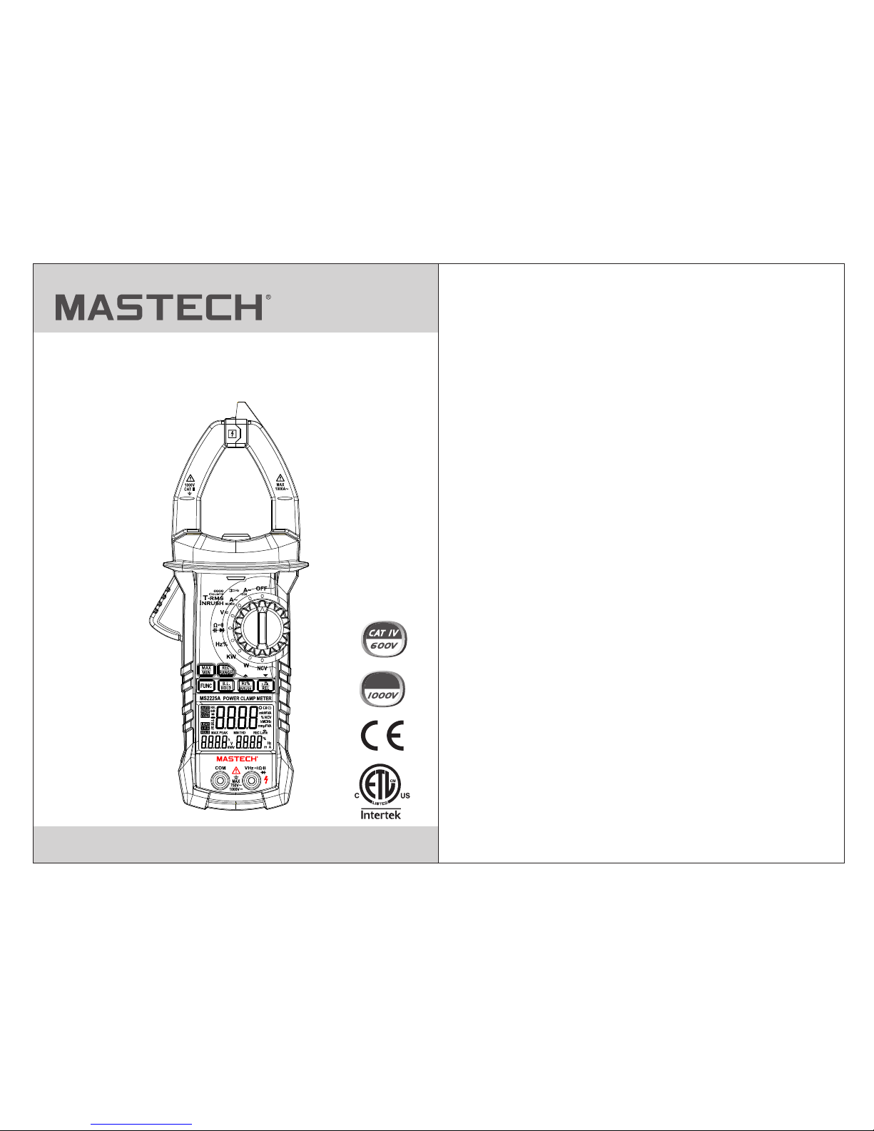
Digital Clamp Power Meter
Operation Manual
MS2225A
CAT III
Page 2

CONTENTS CONTENTS
1. Safety information ..............................................01
1.1 Preparation ...............................................01
1.2 Use ...........................................................02
1.3 Mark ..........................................................03
1.4 Maintenance .............................................04
2. Description .........................................................04
2.1 Name of parts ...........................................06
2.2 Descriptions of switch, button and input jack
..................................................................07
2.3 LCD display ..............................................09
3. Specification .......................................................11
3.1 General .....................................................11
3.2 Technical specifications ............................12
3.2.1 Alternating current .........................12
3.2.2 Inrush current ................................12
3.2.3 DC voltage ....................................13
3.2.4 AC voltage .....................................13
3.2.5 Frequency .....................................14
3.2.6 Duty ratio .......................................15
3.2.7. Resistance ...................................16
3.2.8 Circuit continuity test .....................16
3.2.9. Capacitance .................................16
3.2.10 Diode test ....................................17
3.2.11 Single-phase active power ..........17
3.2.12 Single-phase apparent power .....18
3.2.13 Single-phase reactive power .......18
3.2.14 Power factor ................................19
3.2.15 Harmonics measurement ............19
4 Operation Guide .................................................19
4.1 Reading holding ........................................19
4.2 Manual range ............................................20
4.3 Switchover of frequency and duty ratio .....20
4.4 Selection of maximum/minimum value
measurement ...........................................21
4.5 Function switching ....................................21
4.6 Measurement of relative value .................22
4.7 LINK measurement ...................................22
4.8 REC function ............................................23
4.9 ▼function ..................................................23
4.10 ▲function ................................................24
4.11 INRUSH measurement ...........................24
4.12 Back-light and clamp lighting .................24
4.13 Automatic shutdown ...............................25
Page 3
01
4.14. Measurement preparation ......................25
4.15 AC current measurement ........................26
4.16. Voltage measurement ............................28
4.17 Measuring frequency and duty ratio ........30
4.18 Resistance measurement .......................34
4.19 Diode test ................................................36
4.20 Circuit continuity test ...............................38
4.21 Capacitance measurement .....................40
4.22 Measurement of inrush current ...............42
4.23 NCV measurement ................................. 44
4.24 Active power measurement .....................46
4.25 Apparent power measurement ................48
4.26 Power factor measurement .....................50
4.27 Phase angle measurement .....................52
4.28 Harmonics measurement (voltage signal)
..............................................................53
4.29 Harmonics measurement (current signal)
...............................................................56
5 Maintenance .......................................................58
5.1 Battery replacement ..................................58
5.2 Replacing Test Leads.............................. 58
6 Attachments ........................................................59
CONTENTS
1. Safety information
Please pay special attention when using this meter,
improper use may result in electric shock or damage to the
meter. Please follow the common safety rules, and fully
comply with the safety precautions specified in the user
manual.
To make full use of the meter, and ensure safe operation,
please read carefully and follow the application methods in
this specification.
WARNING
This meter conforms to IEC 61010 Safety Requirements of
Electronic Measuring Instrument. It causes secondary pollution,
and the over-voltage standard is CAT IV 600 V and
CAT III 1000V. Please abide by the safe operation guidance to
ensure the safety use of the meter. Appropriate use and
protection of the meter will bring you satisfactory service
1.1 Preparation
1.1.1 The users must comply with the following safety
regulations when using the meter:
- General electric shock protection
- Prevent the misuse of the meter
1.1.2 After receiving the meter, check whether it is damaged in
the transportation.
1.1.3 Check and verify whether the meter is damaged after
being stored and shipped in poor condition.
1.1.4 The probe must be in good condition. Check whether the
insulation of the probe is broken and the metal wire of the
conductor is exposed before using.
Page 4
1.1.5 The probe provided with the meter can ensure the safe
use, and it must be replaced with the same probe or the
probe of the same grade, if necessary.
1.2 Use
1.2.1 You must use the meter according to requirements of
correct functions and measuring range.
1.2.2 Do not exceed the indicated value of protection scope of
each measuring range during the measurement.
1.2.3 Do not touch the top of the probe when the meter is
connected for measuring the circuit.
1.2.4 During the measurement, if the measured voltage is
higher than 60V DC or 30 V AC (effective value), you
should keep your fingers behind the probe protector all
the time.
1.2.5 Do not measure the voltage when the AC voltage
between the measuring terminal and the ground is
greater than 750 V.
1.2.6 Select the highest range of the manual range if you don't
know the measured value in advance.
1.2.7 Remove the probe from the measured circuit before
rotating the change-over switch to change the measuring
function.
1.2.8 Do not perform the live line measurement for the
resistance, capacitance, diodes and circuit continuity.
1.2.9 Do not connect the meter to the voltage source during
the current, resistance, capacitance, diodes and circuit
continuity test.
1.2.10 Do not measure the capacitance before the capacitor is
fully discharged.
1.2.11 Do not use this meter near the explosive gas, steam or
dust.
1.2.12 In case of any abnormality or fault, please stop using
the meter.
1.2.13 Do not use this meter, unless the bottom case and the
battery cover are fully fastened in situ.
1.2.14 Do not store or use this meter in direct sunlight, high
temperature, or high humidity.
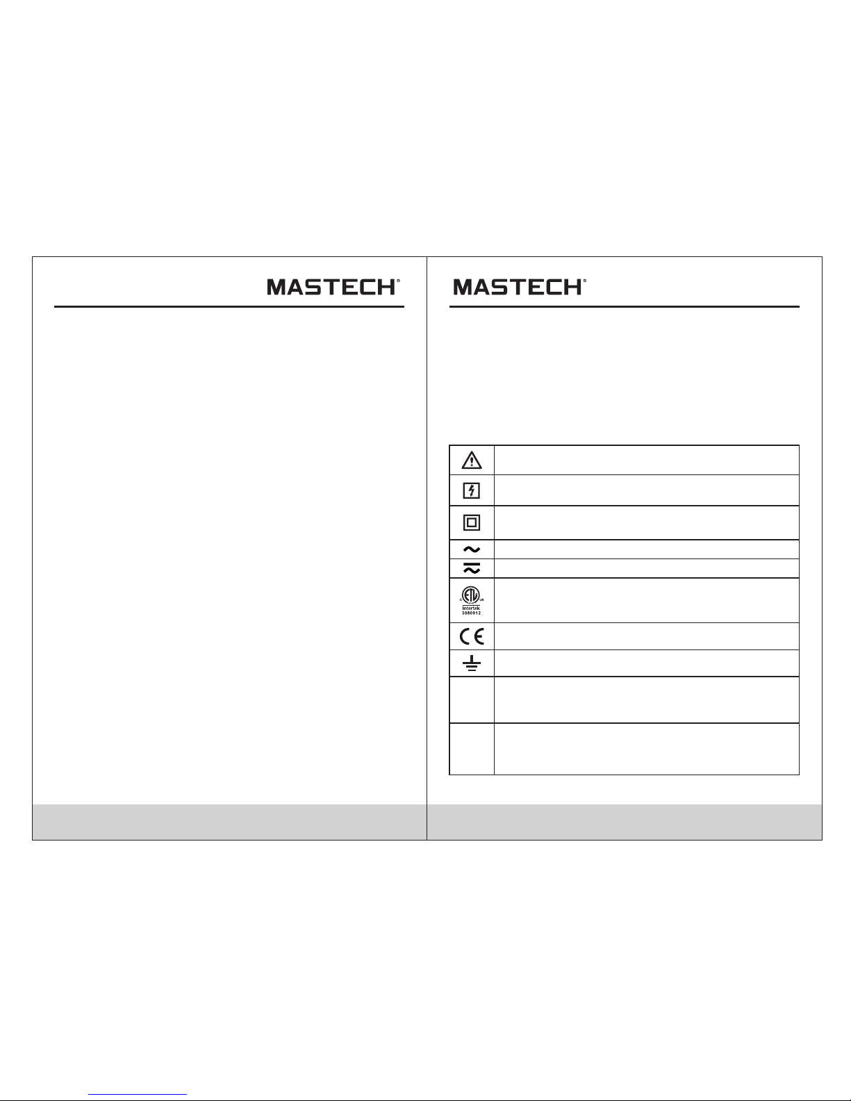
1.3 Mark
Note-Important safety information, refer to the
instruction manual.
Application around and removal from UNINSULATED
HAZARDOUS LIVE conductors is permitted.
Complies with European (EU) safety standards
Conforms to UL STD. 61010-1, 61010-2-032,
61010-2-033; Certified to CSA STD C22.2 NO.
61010-1, 61010-2-032,61010-2-033
Earth (ground) TERM INAL
CAT III
It i s applica ble to test a nd measur ing circuits
co nnected to the distributi on part of the
bu ilding's low-v oltage MA INS insta llation .
Equipment protected throughout by double
insulation or reinforced insulation.
Alternating current
Both direct a nd al terna ting cu rrent
MEASUREMENT CATEGORY IV is applicable to
test and measuring circuits connected at the source
of the building’s low-voltage MAINS installation.
CAT IV
02 03
Page 5
04 05
1.4 Maintenance
1.4.1 Do not try to open the bottom case of the meter for
adjustment or repair. These operations can only be
performed by the technicians who understand the meter
and the shock hazard adequately.
1.4.2 Please remove the probe from the measured circuit
before opening the bottom case or the battery cover of
the meter.
1.4.3 In order to avoid the electric shock caused by the
incorrect reading, when the meter displays ""
replace the battery immediately.
1.4.4 Use wet cloth and mild detergent to clean the meter, and
do not use the abrasive or solvent.
1.4.5 Turn off the power of meter when you don't use it, rotate
the range switch to the OFF gear.
1.4.6 Take off the battery to prevent the damage to the meter,
if you do not use it for a long time.
2. Description
-MS2225A single-phase clamp-type harmonic power meter is
hand-type intelligent power measuring meter, which combines
the digital multimeter and power measurement with Bluetooth
function. The range switch with one-handed performance is
convenient for the measurement, and this meter can perform
the functions of overload protection and low battery indicator.
- The meter can be used for the measurement of the
alternating current, alternating voltage, direct voltage,
frequency, duty ratio, resistance and capacitance and circuit
continuity, diode test, non-contact voltage detection, as well as
the measurement of the active power, reactive power,
apparent power, power factor, harmonics measurement and
phase angle measurement.
- The meter supports the auto range and manual range.
- The meter supports reading holding.
- The meter supports maximum measurement.
- The meter supports minimum measurement.
- The meter supports relative measurement.
- The meter supports Bluetooth.
- The meter supports data storage.
- The meter supports back-light and clamp lamp.
- The meter supports automatic shutdown.
- The meter supports low voltage indicator.
Page 6
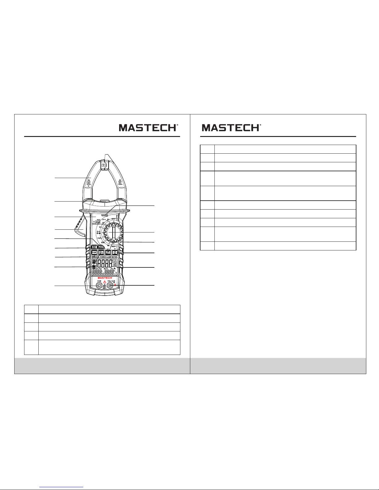
2.1 Name of parts
(1)
Current clamp: for current measurement.
(2)
Clamp lamp
(3)
Faceplate
(4)
Trigger
(5)
Button for data storage and switch of auto and
manual range
(6)
Button for maximum/minimum selection
(7)
Button for function switch
(8) Button for reading holding/back-light
(9)
Button for frequency and duty ratio measurement,
inrush current and up
(10)
Button for Bluetooth function, relative
measurement and down
(11) Change-over switch
(12) NC V indic ator li ght
(13)
LCD display
(14)
Input jack of resistance, capacitance, voltage,
frequency, di ode and c ontin uity.
(15)
Jack of common terminal
12
11
1
2
3
4
5
6
7
8
14
9
10
13
15
2.2 Descriptions of switch, button and
input jack
FUNC button: for switching the measurement function.
B.L/HOLD button: the readings will be held by the short press,
and the back-light will be turned on by long press. The backlight and clamp lamp will be turned on at the same time by
pressing the B.L/HOLD button in the current gear and in the
power gear on the current interface.
REC/RANGE button: short press for switching between auto
and manual range mode, and long press for data storage.
LINK/REL/▼ button
1) Long press for validating Bluetooth in all gears.
2) Short-press in the harmonic measurement interface at KW
and W gears to scroll down, and to switch between the 1st
06 07
Page 7
08 09
harmonic and 20th harmonic. At the KW and W gears, shortpress the function key in the maximum/minimum value
measurement interface to scroll down, and switch and display
the maximum/minimum value.
3) Short press on alternating current, AC/DC voltage and
capacitance for relative value measurement mode.
Hz%/INRUSH/▲button
1) Short press on alternating current, alternating voltage and
HZ% gear for the switch among alternating current or
alternating voltage, frequency and duty ratio.
2) Short-press on the harmonic measurement interface at KW
and W gears to scroll up, and switch between the 1st harmonic
and 20th harmonic. At the KW and W gears, short-press the
function key in the maximum/minimum value measurement
interface to scroll up, and switch and display the
maximum/minimum value.
3) Long press on the alternating current gear for switching to
the measurement mode of inrush current.
MAX/MIN button: for the switch between the
maximum/minimum measurement.
OFF gear: for power off.
INPUT jack: input terminal of voltage, resistance, frequency,
duty ratio, capacitance, diode and circuit continuity.
COM jack: common terminal of voltage, resistance, frequency,
duty ratio, capacitance, diode and circuit continuity.
Change-over switch: for selection of functions and ranges.
2.3 LCD display
Alternating current/Direct current
Diode and continuity
Auto range mode
Status of maximum measurement
Status of minimum measurement
Status of relative measurement
Status of automatic shutdown
LOW BATT ERY
Status of reading holding
HOLD
HZ
Frequency measurement
Percentage (duty ratio)
Millivolt, volt (voltage)
Ampere (electric current)
Nano farad, microfarad and millifarad
Ohm, kilo-ohm and megohm (resistance)
Hertz, kilohertz and megahertz (frequency)
Page 8
Non-contact voltage detection
Watt and kilowatt (active power)
Unit of apparent power
Reactive power
Phase angle
Peak value measurement
Total harmonic distortion
Total harmonic distortion F (relative to
fundamental wave)
Total harmonic distortion r (relative to
actual effec tive va lue)
Power factor
Phase
Status of inrush current measurement
Data recorder
Bluetooth function
Leading phase angle
Lagging phase angle
Hour (time unit)
Negative sign
W,KW
VA, KVA
Var, KVAr
O
PEAK
THD
H01F
H01r
COSФ
Phase
INR
REC
LEAD
LAG
h
3. Specification
Recalibrate the meter under the conditions of 18°C~28°C
and the relative humidity less than 75%, with the
calibration cycle of 1 year.
3.1 General
Auto range and manual range.
Full-scale overload protection.
Maximum allowable voltage between measured end
and the ground: 1000 V DC or 750 V AC .
Worki ng heig ht: les s than 2, 000 m.
Displayer: LCD.
Maximum displayed value: 5999 dgt.
Polar indication: self-indicating, "-" means negativ e
polarity.
Over-range display: '0L' or '-0L'.
Sampling time: around 3 times/s.
Unit display: display the functions and the unit of
electric quantity.
Time of automatic shutdown: 30 minutes.
Power supply: DC power supply 9 V.
Type of battery: NEDA 1604 or 6F22.
Under-voltage indication of battery: LCD display
symbol.
1
2
3
4
5
6
7
8
9
10
11
12
13
14
15
Temperature coeffic ient: l ess tha n 0.1×d egree o f
accuracy/°C.
10 11
Page 9
16
Worki ng temp eratu re: 18° C~28° C.
Storage temperature: -10°C~50°C.
17
1819Dimension: 238×92×50 mm.
Weigh t: arou nd 420 g (i nclud ing bat tery) .
3.2 Technical specifications
Environmental temperature: 23±5°C relative
humidity: ≤ 75%
3.2.1 Alternating current
Range
Resolution
Accuracy
±(2.0% rdg+ 8 dgt)
60A 0.01A
600A 0.1A
1000A
1A
- Maximum input current: 1000A AC
- Frequency range: 40~400 Hz
3.2.2 Inrush cu rrent
Range
Resolution
Accuracy
<60 A (fo r refer ence on ly)
±(5% rdg+ 60 dgt)
60A 0.01A
600A 0.1A
1000A
1A
Integral time: 100 ms; measurement range: 20~1000 A;
frequency range: 40~400 Hz
3.2.3 DC voltag e
Range
Resolution
Accuracy
±(0.5% rdg+ 5 dgt)
-Input impedance: 10M
-Maximum input voltage: 750 V AC (effecti ve valu e) or
1000 V DC.
6V
60V
600V
1000V
0.001V
0.01V
0.1V
1V
±(0.8% rdg+ 4 dgt)
3.2.4 AC voltage
Range
Resolution
Accuracy
±(0.6% rdg+ 4 dgt)
- Input impedance: 10M
- Maximum input voltage: 750 V AC (effecti ve valu e) or
1000 V DC.
- Frequency range: 40~400 Hz.
±(0.8% rdg+ 4 dgt)
6V
60V
600V
750V
0.001V
0.01V
0.1V
1V
Note:
Under the small voltage range, there might be reading o n
the meter before the probe is connected to the measured
circuit.
The above phenomenon is normal because the meter has
high sensitivity and it has no influence on the actual
measurement result.
12 13
Page 10
3.2.5 Frequency
3.2.5.1 Frequ ency measurement with clam p
(at A g ear):
Range
Resolution
Accuracy
±(1.5% rdg+ 5 dgt)
99.99Hz
999.9Hz
0.01Hz
0.1Hz
- Measurement range: 10 Hz~1 kHz
- Range of input signal: ≥ 20A AC (t he inpu t curre nt is
increased with the measured frequency)
- Maximal input current: AC 1 000 A (e ffective value)
3.2.5.2 At V gear:
Range
Resolution
Accuracy
±(1.5% rdg+ 5 dgt)
99.99Hz
999.9Hz
9.999kHz
0.01Hz
0.1Hz
0.001kHz
- Measurement range: 10 Hz~10kHz
- Range of input voltage: ≥ 1 V AC (eff ectiv e value ) (the
input voltage is increased with the measured frequency)
- Input impedance: 10MΩ
- Maximum input voltage: 750 V AC (effecti ve valu e)
3.2.5.3 At HZ/DUTY gear:
Range
Resolution
Accuracy
±(0.3% rdg+ 5 dgt)
9.999Hz
99.99Hz
999.9Hz
9.999kHz
99.99KHZ
999.9KHZ
9.999MHZ
±(0.3% rdg+ 5 dgt)
0.001Hz
0.01Hz
0.1Hz
0.001kHz
0.01kHZ
0.1KHZ
0.001MHZ
- Overload protection: 1000 V DC or 750 V AC (effecti ve
value)
- Range of input voltage: ≥ 2 V (the input voltage is
increased with the increase of the measured frequency)
3.2.6 Duty ratio
Range
Resolution
Accuracy
±(3.0% + 3 )
0.1 - 99.9%
0.1%
- Frequency response: 10 ~ 1 kHz.
- Range of input current: ≥ 20 A A C (effective value)
-Maximal input current: AC 1000 A
3.2.6.1 At A gear (from the clamp):
3.2.6.2 At V gear:
- Frequency response: 10 ~ 10kHz.
- Range of input voltage: 1 V AC.
- Input impedance: 10MΩ
- Maximum input voltage: 750 V AC (effecti ve valu e)
- Frequency response: 10 ~ 10MHz.
- Range of input voltage: ≥ 2V AC ( effective value) (the
input voltage is increased with the measured frequency)
- Maximum input voltage: 250V AC (effe ctive v alue)
3.2.6.3 At HZ/DUTY gear:
14 15
Page 11

16 17
3.2.7. Resistance
Range
Resolution
Accuracy
±(0.8% rdg+ 3 dgt)
600Ω
6kΩ
60kΩ
600kΩ
6MΩ
60MΩ
0.1Ω
0.001kΩ
0.01kΩ
0.1kΩ
0.001MΩ
0.1MΩ
±(2% rdg+ 5 dgt)
- Open-circuit voltage: around 0.78 V
- Overload protection: 1000 V DC or AC ( effective value)
3.2.8 Circuit continuity test
Range
Resolution
Function
600Ω 0.1Ω
If the resistance of measured
circuit is less than 50Ω, the
buzzer inside the meter will
send a sound.
- Open-circuit voltage: around 1.48V
- Overload protection: 1000 V DC or 750 V AC (effecti ve
value)
3.2.9. Capacitance
Range
Resolution
Accuracy
±(3.0% rdg+ 5 dgt)
9.999nF
99.99nF
999.9nF
9.999µF
99.99µF
0.001nF
0.01nF
0.1nF
0.001µF
0.01µF
±(3.0% rdg+ 5 dgt)
999.9µF
9.999mF
99.99mF
0.1µF
0.001mF
0.01mF
- Overload protection: 1000 V DC or 750 V AC (effecti ve
value)
3.2.10 Diode test
Range
Resolution
Function
3V 0.001V
Display the approximate
value of diode forward
voltage
- DC forward current is around 1 mA
- DC reverse voltage is around 3.2 V
- Overload protection: 1000 V DC or 750 V AC (effecti ve
value)
3.2.11 Single-phase active power
Range
Resolution
Accuracy
±(3.0% rdg+ 5 dgt)
3W
100W
4000W
10kW
100kW
750kW
0.01W
0.1W
1W
0.01kW
0.1kW
1kW
Page 12

18 19
Minimum input current: 1 mA, and minimum input
voltage: 1 V.
3.2.12 Single-phase apparent power
Range
Resolution
Accuracy
±(3.0% rdg+ 5 dgt)
0.01VA
0.1VA
1VA
0.01kVA
0.1kVA
1kVA
3VA
100VA
4000VA
10kVA
100kVA
750kVA
Minimum input current: 1 mA, and minimum input
voltage: 1 V.
3.2.13 Single-phase reactive power
Range
Resolution
Accuracy
±(3.0% rdg+ 5 dgt)
Minimum input current: 1 mA, and minimum input
voltage: 1 V.
3W
100W
4000W
10kW
100kW
750kW
0.01W
0.1W
1W
0.01kW
0.1kW
1kW
3.2.14 Power factor
Range
Resolution
Accuracy
0.3 ~ 1 capacitive
0.3 ~ 1 inductive
0.001
0.001
±(3.0% rdg+ 5 dgt)
Minimum input current: 1 mA, and minimum input
voltage: 1 V.
3.2.15 Harmonics measurement
Range
1
2-6
7-8
9-10
11-15
16-20
±(3.0% rdg+ 10 dgt)
±(3.5% rdg+ +10 dgt)
±(4.5% rdg+ 10 dgt)
±(5.0% rdg+ 10 dgt)
±(7.0% rdg+ 10 dgt)
±(10.0% rdg+ 10 dgt)
Accuracy of harmonic electrical level
Minimum input current: 1 mA, and minimum input
voltage: 1 V.
4. Operation Guide
4.1 Reading holding
1) During the measurement, if the reading shall be held ,
short-press the "HOLD/B.L" key to lock the display
value of the display, an d short -pres s the "HO LD/B. L"
key to unlock the kept reading.
Page 13

4.2 Manual range
The RANGE key is used for setting the auto/manual range,
and this key can be activated through triggering. Its
startup default state is auto range. Press the key once to
switch to the manual range. In the manual range mode,
move the meter to the next higher gear after pressing the
key once, and after moving to the highest gear, press the
key continuously to move the meter to the lowest gear.
Perform the cyclic operations in sequence. If press the
key for more than 2 s, the meter will be switched to the
state of auto range.
Note:
During the measurement of diode, continuity test,
capacitance, and frequency KW, W and NCV gear, the
manual range is unavailable.
4.3 Switchover of frequency and duty ratio
1) When the meter is at AC c urren t gear, sh ort-p ress th e
"Hz/%/INRUSH/▲" key, the me ter can b e in Hz
measurement state to measure the frequency of
measured AC v oltag e and cur rent si gnals . Then,
short-press the "Hz/%/INRUSH/▲" key again, the meter
will be in DUTY me asure ment st ate to me asure t he duty
ratio of measured voltage and current signals. If the
meter is in HZ/% gear, short-press "Hz/%/INRUSH/▲"
key to switch the meter to the HZ and DUTY st ates
circularly.
2) If the meter is in AC current and AC/DC voltage gear,
short-press the "Hz/%/INRUSH/▲" key, th e meter w ill
be in the voltage and current measurement state.
4.4 Selection of maximum/minimum value
measurement
1) Press the "MAX/MIN" key in the kW and W gear, the
interface will simultaneously display the maximum and
minimum values obtained after the test for a period of
time, and then press the ▲or ▼key on this interface to
enter the interface displaying the time of record. After
that, the specific time period of these maximum and
minimum values will be displayed.
2) When the meter is at AC c urren t gear, AC/ DC volt age
gear and resistance gear, press the "MAX/MIN" to enter
the MAX mode and measure the maximum value all the
time; press "MAX/MIN" key once again to enter the state
for measuring the minimum value; and then press the
"MAX/MIN" key for the third time to exit the
measurement mode of maximum and minimum value.
Note:
1) The me ter is in m anual r ange mo de unde r the
measurement states of max/min value.
4.5 Function switching
1) Long-press the FUNC key in the power measurement
interface to enter the power, voltage and current
measurement interface.
2) Short-press the FUNC key in the power measurement
interface to enter the active power, apparent power,
reactive power, power factor and phase angle
measurement interface.
3) When the meter is at power gear, short-press the FUNC
key in the voltage measurement interface to enter the
voltage effe ctive v alue, h armon ic, har monic d istor tion
rate TH D-R and h armon ic dist ortio n rate THD-F
measurement interface.
20 21
Page 14

22 23
4) When the meter is at power gear, short-press the FUNC
key in the current measurement interface to enter the
current effe ctive v alue, h armon ic, har monic d istor tion
rate TH D-R and h armon ic dist ortio n rate THD-F
measurement interface.
5) When the meter is at DC/AC gear, short-press the FUNC
key to switch between the DC voltage measurement and
AC voltage measurement interface.
6) When the meter is at resistance/diode/buzzer/
capacitance gear, short-press the FUNC key to switch
among resistance, diode, buzzer and capacitance
measurement.
4.6 Measurement of relative value
1) Short-press the LINK/REL/▼ key at AC current, AC /DC
voltage and capacitance gears to enter the relative
value measurement mode and store the current
displaying value in memory as the reference value. For
the sequent measurement, the displayed value is the
diffe rence v alue be tween t he inpu t value a nd refe rence
value, i.e. REL▲ (current reading) = input value reference value.
2) This function of relative value measurement only can b e
available in the manual measurement mode.
4.7 LINK measurement
At any gear (excluding OFF gear), long-press LINK/REL/▼
to turn on the Bluetooth of meter. Then op en the
corresponding AP P (iOS or Android) of the meter through
mobile phone or other equipment and search the signal t o
link them. Af ter the l inkin g, the APP will display the
content displayed on meter in real time. Long-press the
LINK/REL/▼ key once again, the Bluetooth of meter will
be turned off an d the met er will b e disco nnect ed from t he
APP.
4.8 REC function
The meter performs the functions of data recording and
Bluetooth data reading.
1) Data recording: the meter can save 1000 pieces of
data records. Long-press REC/RANG key to enable
the meter to record data. The RE C indic ator on L CD
will be on, and the meter will store the current
measurement data at the rate of 3 times/s. Long-press
REC key again to exit the data recording function. Th e
meter also can exit the data recording function when
the 1000 pieces of data are recorded or a key operation
or gear switching operation is performed.
2) Data reading: the meter cannot support the direct
reading of stored data, and it only support the reading of
the stored data with the Bluetooth function through a
specific AP P on the mobile phone.
4.9 ▼function
Short-press LINK/REL/▼ in the harmonic measurement
interface at KW and W gears to scroll down, and to switch
between the 1st harmonic and 20th harmonic. At the KW
and W gears, short-press the function key in the
maximum/minimum value measurement interface to
scroll down, and switch and display the
maximum/minimum value.
Page 15

4.10 ▲function
Short-press in the harmonic measurement interface at
KW and W gears to scroll up, and to switch between the
1st harmonic and 20th harmonic. At t he KW and W g ears,
short-press the function key in the maximum/minimum
value measurement interface to scroll up, and switch and
display the maximum/minimum value.
4.11 INRUSH measurement
Long-press "Hz/%/INRUSH/▲" for more than 2 s at AC
current gear to enterthe inrush measurement state.
4.12 Back-light and clamp lighting
1) During measurement, if the ambient light is too dim to
read, press the "B.L/HOLD" for more than 2 s to turn on
the back-light, and the back-light will be off 20 s lat er.
2) In this period, press the "B.L/HOLD" key for 2 s to turn
off the b ack-l ight.
3) Turn on the back-light of the meter at the current gear,
and the clamp lamp will be on at the same time.
The lum inous o bject o f the bac k-lig ht is LED w ith hig h
working current.
Although this meter is set with timing circuit (with time
of 30 s), the service life of battery will be shortened
with frequent use of back-light.
There fore, y ou shal l minim ize the u se of bac k-lig ht as
far as possible under the unnecessary conditions.
Note:
When the battery voltage ≤ 7.2 V, the display will displa y
the symbol of " "(under-voltage). However,
if the back-light is used, when the battery voltage ≥ 7.2 V,
the battery voltage is reduced due to high working current,
the display may display the symbol " "(when the
symbol of " " is displayed, the measurement accuracy
cannot be guaranteed). Under such circumstance, the
battery will not be replaced until the symbol " " is
displayed without back-light.
4.13 Automatic shutdown
1) After startup, in case of no operation within 30 minutes,
the meter will enter the dormant state and shut down
automatically for saving electric energy. There will be
voice prompt (a prolonged blast) from the buzzer 1
minute before shutdown, and then the meter will shut
down automatically.
2) After shutdown, press FUNC key and the meter will
resume operation.
3) If the "B.L/HOLD" key is pressed during startup, the
function of automatic shutdown will cancel automatical ly.
4.14. Measurement preparation
1) Turn the change-over switch to power on the meter. If
the battery is in under-voltage state (the voltage ≤ 7.2 V),
the display will display the symbol " ", and then the
battery shall be replaced.
2) " " means that the input voltage or current shall not
be greater than the indicated value in order to prevent
the internal circuit from damage.
3) Turn the change-over switch to the required
measurement function and range.
4) For wiring, connect the public testing line at first and
then connect the energized testing line. For
disconnecting,remove the energized testing line at firs t.
24 25
Page 16

26 27
4.15 AC current measurement
WARNING
Electric shock.
Remove the probe from the meter before measuring
with the current clamp.
1) Turn the change-over switch to AC current gear. At this
time, the meter is in AC c urren t measu remen t state , and
then the suitable range shall be selected.
2) Hold the trigger, and open the clamp to clamp one
conductor of measured circuits.
3) Read the current value from LCD display.
Note:
1) If two or more circuits of the measured circuits are
clamped, the measurement result will be not correct.
2) In order to acquire the accurate reading, the measured
conductor shall be in the center of clamp as far as
possible.
3) " " means that the maximum AC input current is
1000 A.
4) When the reading is greater than 600.1 A at 60 A/600 A ,
there will be the alarm sound "beep" from the meter.
When the reading is greater than 620 A rm s, the ACA wi ll
display overload.
5) When the reading is greater than 1001 A a t 1,000 A,
there will be the alarm sound "beep" from the meter.
When the reading is greater than 1,100 A rms, the AC A
will display overload.
Figur e 1 Sch ema tic Diagram for Curr ent M eas urement at AC Gear
Page 17

this case, the meter is in the DC voltage measurement
state. If the AC voltage shall be measured, press the
FUNC key and the meter will enter the AC v oltag e
measurement state.
3) Connect the probe to both ends of voltage source or
load to conduct measurement.
4) Read the voltage value from LCD.
Note:
1) The au to rang e will be u navai lable u nder th e relat ive
measurement mode.
2) " " means that the maximum input voltage is 750 V
AC or 1000 V DC.
3) Ther e will be t he alar m sound " beep" f rom the m eter,
when the measured reading of the meter is greater than
600 V rms ACV.
When the reading is greater than 750 V rms ACV, the
meter will display overload.
4) Ther e will be t he alar m sound " beep" f rom the m eter,
when the measured reading of the meter is greater than
1000 V rms DCV.
When the reading is greater than 1100V r ms, the D CV
will display overload.
4.16. Voltage measurement
WARNING
Electric shock.
Pay special attention to high voltage measurement to
avoid electric shock.
Do not input the voltage with the effec tive va lue
greater than AC 750.
1) Plug the black probe into COM jack, plug the red probe
into INPUT jac k, and se lect th e suita bleran ge.
2) Turn the change-over switch to AC/DC voltage gear. In
Figur e 2: Sc hem atic Diagram for AC Vo lta ge Me asurement at
AC/DC Volta ge Ge ar
28 29
Page 18

30 31
4.17 Measuring frequency and duty ratio
1) Frequency me asurement with clamp (at
current gear) :
WARNING
Electric shock.
Remove the probe from the meter before measuring
with the current clamp.
(1) Turn the change-over switch to AC c urren t gear.
(2) Hold the trigger, and open the clamp to clamp one
conductor of measured circuits.
(3) Press the "Hz/%INRUSH/▲"button shortly to switch
into the status of frequency measurement.
(4) Read the frequency value from LCD display.
(5) Press "Hz/%INRUSH/▲"again to enter the status of
duty ratio measurement.
Note:
(1) If two or more circuits of the measured circuits are
clamped, the measurement result will be not correct.
(2)The measurement range of frequency is 10 Hz ~ 1 kHz.
If the measured frequency is less than 10 Hz, the
frequency greater than 10 kHz might be measured, but
the accuracy of measurement cannot be guaranteed.
(3) The m easur ement r ange of d uty rat io is 10 ~ 95 %.
(4) The m aximu m input c urren t of " " is 100 0A AC
(effe ctive v alue) .
2) At voltage gear:
WARNING
Electric shock.
Pay special attention to high voltage measurement to
avoid electric shock.
Do not input the voltage with effecti ve valu e great er
than AC 750.
(1) Insert the black probe into COM jack, and insert the red
probe into INPUT jack .
(2) Turn the change-over switch to AC /DC vol tage ge ar,
press FUNC to enter the status of AC voltage
measurement.
(3) Press the "Hz/%INRUSH/▲"button to switch into the
frequency measurement state.
(4) Connect the probe to both ends of signal source or
load to conduct measurement.
(5) Read on the LCD.
(6) Press "Hz/%INRUSH/▲"again to enter the status of
duty ratio measurement.
Note:
(1) The m easur ement r ange of f reque ncy is 10 H z ~ 10kHz .
If the measured frequency is less than 10 Hz, the LCD
will display "00.0", the frequency less than 10 kHz
might be measured, but the accuracy of measurement
cannot be guaranteed.
(2) The m easur ement r ange of d uty rat io is 10 ~ 95 %.
(3) The m aximu m input v oltag e of " " is 750 V AC
(effe ctive v alue) .
Page 19

32 3 3
3) At HZ/DUTY gear :
WARNING
Electric shock.
Pay special attention to high voltage measurement to
avoid electric shock.
Do not input the voltage with effecti ve valu e great er
than AC 750 V.
(1) Insert the black probe into COM jack, and insert the red
probe into INPUT jack .
(2) Turn the change-over switch to HZ% gear.
(3) Connect the probe to both ends of signal source or load
to conduct measurement.
(4) Read on the LCD.
(5) Press "Hz/%INRUSH/▲"again to enter the status of
duty ratio measurement.
Note:
The measurement range of frequency is 10 Hz ~ 9.999
MHz, if the measured frequency less than 10 Hz, the LCD
will display "00.0"; the frequency greater than 9.999 MHz
might be measured, but the accuracy of measurement
cannot be guaranteed.
Figur e 3: Sc hem atic Diagram for Fre que ncy M easurement at
HZ% Gear
Page 20

34 35
4.18 Resistance measurement
WARNING
Electric shock.
When measuring the impedance on the circuit, the
circuit power should be disconnected, and the
capacitor in the circuit should be completely
discharged.
1) Insert the black probe into COM jack, and insert the red
probe into INPUT jack .
2) Place the change-over switch on the gear, and set
the meter in the status of resistance measurement.
3) Connect the probes to both ends of the measured
resistor or the circuit for measurement.
4) Read on the LCD.
Note:
1) When the input is open-circuited, the LCD will display
"0L" for over range.
2) If the resistance of measured resistor is greater than
1 MΩ, the reading of the meter might be stable after a
few seconds, and it is common for the high resistance
readings.
Figur e 4 Sch ema tic Diagram for Resi sta nce M easurement at
Gear
Page 21

36 37
4.19 Diode test
1) Insert the black probe into COM jack, and insert the red
probe into INPUT jack .
2) Turn the change-over switch to the gear.
3) Press "FUNC" to switch into the status of
measurement.
4) Connect the red probe to the positive pole of the diode,
and connect the black probe to the negative pole for
measurement.
5) Read on the LCD.
Note:
1) The ap proxi mate va lue of th e forwa rd volt age dro p of
diode will be displayed on the meter.
2) If the probe is connected inversely or the probe is
open-circuited, the LCD will display "0L".
Figur e 5 Sch ema tic Diagram for Diod e Te sting at Gear
Page 22

38 39
4.20 Circuit continuity test
WARNING
Electric shock.
For the circuit continuity test, the circuit power should
be disconnected, and the capacitor in the circuit
should be completely discharged.
1) Insert the black probe into COM jack, and insert the red
probe into INPUT jack .
2) Turn the change-over switch to the gear.
3) Press "FUNC" button to switch to the status of
circuit continuity testing.
4) Connect the probes to both ends of the circuit for
measurement.
5) If the resistance of measured circuit is less than 50Ω ,
the buzzer inside the meter will make a sound.
6) Read the resistance value of the circuit from LCD.
Note:
If the probe is open-circuited or the resistance of the
measured circuit is greater than 600Ω , the "0L" will be
displayed.
Figur e 6 Sch ema tic Diagram for Circ uit C ont inuity Test at
Gear
Page 23

40 41
4.21 Capacitance measurement
WARNING
Electric shock.
To avoid electric shock, the capacitor should be
completely discharged before the capacitance
measurement.
1) Insert the black probe into COM jack, and insert the red
probe into INPUT jack .
2) Turn the change-over switch to the gear.
3) Connect the probe to the both ends of the measured
capacitor for measurement after the capacitor is
completely discharged.
4) Read the capacitance value from LCD.
Note:
To improve the accuracy of the measured value less than
10 nF,t he dist ribut ed capa citan ce of the m eter an d
conductors should be subtracted.
Figur e 7 Sch ema tic Diagram for Capa cit ance Measurement a t
Gear
Page 24

42 4 3
4.22 Measurement of inrush current
WARNING
Electric shock.
Remove the probe from the meter before measuring
with the current clamp.
4.22.1 Turn the change-over switch to 60/600 A o r 1000 A
AC current gear.
4.22.2 Hold the trigger, and open the clamp to clamp one
conductor of measured circuits.
4.22.3 Long press the "HZ%/INRUSH/▲" button more
than 2 seconds to enter the mode of inrush current
measurement. Then t he LCD wi ll disp lay "IN R", and
the meter will display and hold the inrush current
value until the motor start-up is detected.
4.10.4 Read the inrush current value from LCD display.
Note:
1) If two or more circuits of the measured circuits are
clamped, the measurement result will be not correct.
2) In order to acquire the accurate reading, the measured
conductor shall be in the center of clamp as far as
possible.
3) The LC D only di splay s "OL" in t he manu al rang e mode
indicating the over range, and the higher range should
be selected.
4) Under the manual range mode, if the measured value is
not known in advance, the highest level should be set
for the range.
5) " " means that the maximum input current is 1000A
AC (effe ctive v alue) .
Figur e 8 Sch ema tic Diagram for Inru sh Cu rre nt Measurement at
AC Curre nt Ge ar
Page 25

44 45
4.23 NCV measurement
1) Turn the change-over switch of the meter to the NCV
gear.
2) The to p of the me ter sho uld be ar range d near th e
conductor. When the detected voltage is great than 110
Vac (RMS ), the vo ltage s ensin g indic ator ma y be on,
and the buzzer may make the alarm sound "beep".
Note:
1: The vo ltage m ay stil l exist e ven wit hout in struc tions .
Do not determine whether there is voltage in the
conductor only by using the non-contact voltage
detectors. The detecting operation might be affected by
the socket design, insulation thickness, type and other
factors.
2: When there is input voltage to the input terminal of the
meter, the voltage sensing indicator may also be on.
3: Intrusive sources (such flashlight, motor, etc.) in the
external environment may cause a wrong trigger of
non-contact voltage detection.
Figur e 9 Sch ema tic Diagram for Volta ge De tection at NCV Gear
Page 26

46 47
4.24 Active power measurement
WARNING
Electric shock.
Pay special attention to high voltage and high current
measurement to avoid electric shock.
Do not input the voltage with the effec tive va lue
greater than AC 750 and the current with the effect ive
value greater than 1000 A.
1) Turn the change-over switch to kW or W gear.
2) Clamp the measured conductor of the power supply or
load with the clamp. Input the measured voltage from
the V end and COM end. After the measuring circuits
are connected correctly, th e activ e power s hall be r ead
from the LCD and the LCD displays the eff ectiv e value s
of measured voltage and current simultaneously.
3) Determine whether the switch shall be turned to the KW
gear or W gear according to the measured current. At
the W gear, the measurement range of current is 1 mA 4,000 mA and at the KW gear, the measurement range
of current is 1 A - 10 00 A. The measurement range of
voltage at both the KW gear and W gear is 1 V -750 V.
4) Press MAX/MIN key in the active power measurement
interface to enter the maximum/minimum value
measurement mode, and the LCD will display the
measured value of active power and the maximum and
minimum values of active power within a certain period
simultaneously. Pr ess the H z/%IN RUSH/ ▲ key or
LINK/REL/▼ key again in this interface, the LCD will
display the recording time and real-time measurement
value of active power.
Note:
1) The ma ximum m easur ement r ange of a ctive p ower is
750 kW, and the LCD will display OL for over range.
2) The ma ximum m easur ed curr ent is 40 00 mA a t W gear.
Please do not operate by mistake.
3) The mi nimum m easur ed volt age is 1 V an d the
minimum measured current is 1 mA.
4) The ma ximum m easur ed volt age is 75 0 V and the
maximum measured current is 1000 A.
Figur e10 S che matic Diagram for Act ive P ower Measurement at
KW Gear
Page 27

48 49
4.25 Apparent power measurement
WARNING
Electric shock.
Pay special attention to high voltage and high current
measurement to avoid electric shock.
Do not input the voltage with the effec tive va lue
greater than AC 750 and the current with the effect ive
value greater than 1000 A.
1) Turn the change-over switch to the kW or W gear, press
FUNC key to enter the apparent power measurement
interface.
2) Clamp the measured conductor of the power supply or
load with the clamp. Input the measured voltage from
the V end and COM end. After the measuring circuits
are connected correctly, re ad the ap paren t power f rom
the LCD and the LCD displays the effect ive val ues of
measured voltage and current simultaneously.
3) Determine whether the switch shall be turned to the KW
gear or W gear according to the measured current. At
the W gear, the measurement range of current is 1 mA 4000 mA and at the KW gear, the measurement range
of current is 1 A - 10 00 A. The measurement range of
voltage at both the KW gear and W gear is 1 V -750 V.
4) Press MAX/MIN key in the apparent power
measurement interface to enter the maximum/minimum
value measurement mode, and the LCD will display the
measured value of apparent power and the maximum
and minimum values of apparent power within a certain
period simultaneously. Pr ess the H z/%IN RUSH/ ▲ key
or LINK/REL/▼ key once again in this interface. The
LCD will display the recording time and real-time
measurement value of apparent power.
Note:
1) The ma ximum m easur ement r ange of a ppare nt powe r
is 750 kW, and the LCD will display OL for over range.
2) The ma ximum m easur ed curr ent is 40 00 mA a t W gear.
Please do not operate by mistake.
3) The mi nimum m easur ed volt age is 1 V an d the
minimum measured current is 1 mA.
4) The ma ximum m easur ed volt age is 75 0 V and the
maximum measured current is 1000 A.
Figur e11 Schem ati c Dia gram for A ppa rent Power Measure men t
at KW Gear
Page 28

50 5 1
4.26 Power factor measurement
WARNING
Electric shock.
Pay special attention to high voltage and high current
measurement to avoid electric shock.
Do not input the voltage with the effec tive va lue
greater than AC 750 and the current with the effect ive
value greater than 1000 A.
1) Turn the change-over switch to the kW or W gear, press
FUNC key to enter the power factor measurement
interface.
2) Clamp the measured conductor of the power supply or
load with the clamp. Input the measured voltage from
the V end and COM end. After the measuring circuits
are connected correctly, th e power f actor f rom the L CD
shall be read and the LCD displays the value of reactive
power simultaneously.
3) Determine whether the switch shall be turned to the KW
gear or W gear according to the measured current. At
the W gear, the measurement range of current is 1 mA 4,000 mA and at the KW gear, the measurement range
of current is 1 A - 10 00 A. The measurement range of
voltage at both the KW gear and W gear is 1 V -750 V.
4) Ther e is a phas e difference between the voltage value
and current value of the inductive load and capacitive
load. Generally. the p ower fa ctor is i ndica ted by th e
cosine COSø of phase angle ø. When t he powe r facto r
is negative, it means that the measured load is
capacitive load.
5) The re activ e power i s a indir ectly m easur ed valu e. The
computational formula of kVAr is: , an d
ﻮ22
k kWkVAVAr -=
the value is calculated out with the measured voltage,
current and active power value.
Note:
1) The ma ximum m easur ed curr ent is 40 00 mA a t W gear.
Please do not operate by mistake.
2) The mi nimum m easur ed volt age is 1 V an d the min imum
measured current is 1 mA.
3) The ma ximum m easur ed volt age is 75 0 V and the
maximum measured current is 1000 A.
Figur e12 S che matic Diagram for Po wer F act or Measurement at
KW Gear
Page 29

52 53
4.27 Phase angle measurement
WARNING
Electric shock!
Pay special attention to high voltage and high curren t
measurement to avoid electric shock.
1) Turn the change-over switch to the kW or W gear, press
FUNC key to enter the phase angle measurement
interface.
2) Clamp the measured conductor of the power supply or
load with the clamp. Input the measured voltage from
the V end and COM end. After the measuring circuits
are connected correctly, th e phase a ngle sh all be re ad
from the LCD and the LCD displays the eff ectiv e value s
of measured voltage and current simultaneously.
3) Determine whether the switch shall be turned to the KW
gear or W gear according to the measured current. At
the W gear, the measurement range of current is 1 mA 4,000 mA and at the KW gear, the measurement range
of current is 1 A - 10 00 A. The measurement range of
voltage at both the KW gear and W gear is 1 V -750 V.
4) Ther e is a phas e difference between the voltage vale
and current value of the inductive load and capacitive
load. Generally, the p hase di fference is indicated by the
phase angle ø.
Note:
1) The ma ximum m easur ed curr ent is 40 00 mA a t W gear.
Please do not operate by mistake.
2) The mi nimum m easur ed volt age is 1 V an d the min imum
measured current is 1 mA.
3) The ma ximum m easur ed volt age is 75 0 V and the
maximum measured current is 1000 A.
Figur e 13 Sc hem atic Diagram for Pha se Ang le Measurement at
KW Gear
4.28 Harmonics measurement (voltage
signal)
WARNING
Electric shock.
Pay special attention to high voltage measurement to
avoid electric shock.
Do not input the voltage with the effec tive va lue gre ater
than AC 750.
Page 30

54 5 5
1) Turn the change-over switch to the kW or W gear, first
long-press the FUNC key to enter the voltage
measurement interface, and then short-press the
FUNC key to enter the harmonics measurement
interface, and switch from 1st - 20th harmonic through
pressing the Hz/%INRUSH/▲ key or LINK/REL/▼ key.
2) Input the measured voltage signal from the V end and
COM end.
3) After the measuring circuits are connected correctly,
the eff ectiv e value o f the nth h armon ic comp onent s hall
be read.
4) Short-press the FUNC key in the harmonic
measurement interface once again to enter into TH D-R
(relative to the actual effe ctive v alue) o r THD-F (relative
to the fundamental wave) measurement mode. The
main interface displays the effec tive va lue of th e nth
harmonic component and the minor interface displays
the total harmonic distortion.
5) Press MAX/MIN key in the voltage measurement
interface to enter the maximum/minimum value
measurement mode. In this case, the main interface
displays the measured effe ctive v alue of v oltag e and
the minor interface displays the maximum and minimum
values within a certain period. Press the
Hz/%INRUSH/▲ key or LINK/REL/▼ key again in this
interface to enter into the time recording interface. In
this case, the main interface displays the limited voltage
measurements, and the minor interface displays the
time of maximum and minimum values.
Note:
1) The mi nimum m easur ed volt age is 1 V an d the
maximum measured voltage is 750 V. Th is inte rface w ill
display OL for over 750 V.
WARNING
Electric shock.
Pay special attention to high current measurement to
avoid electric shock.
Do not input the current with the effec tive va lue gre ater
than AC 1000 A.
Figur e 14 Sc hem atic Diagram for Har mon ics Measurement of
Voltag e Sig nal a t KW Gear
Page 31

56 57
4.29 Harmonics measurement (current
signal)
1) Turn the change-over switch to the kW or W gear, first
long-press the FUNC key to enter the current
measurement interface, and then short-press the FUNC
key to enter into the harmonics measurement interface,
and switch from 1st - 20th harmonic through pressing
the Hz/%INRUSH/▲ key or LINK/REL/▼ key.
2) Clamp the measured conductor of the power supply or
load with the clamp.
3) After the measuring circuits are connected correctly,
the eff ectiv e value o f the nth h armon ic comp onent s hall
be read.
4) Short-press the FUNC key in the harmonic
measurement interface once again to enter into TH D-R
(relative to the actual effe ctive v alue) o r THD-F (relative
to the fundamental wave) measurement mode. The
main interface displays the effec tive va lue of th e nth
harmonic component and the minor interface displays
the total harmonic distortion.
5) Press MAX/MIN key in the current measurement
interface to enter the maximum/minimum value
measurement mode. In this case, the main interface
displays the measured effe ctive v alue of c urren t and
the minor interface displays the maximum and minimum
values within a certain period. Press the
Hz/%INRUSH/▲ key or LINK/REL/▼ key again in this
interface to enter into the time recording interface. In
this case, the main interface displays the limited voltage
measurements, and the minor interface displays the
time of maximum and minimum values.
Note:
1) The mi nimum m easur ed curr ent is 1 mA an d the
maximum measured current is 1000A. This in terfa ce
will display OL for over 1000A.
Figur e 15 Sc hem atic Diagram for Har mon ics Measurement of
Curre nt Si gna l at KW Gear
Page 32

58
5 Maintenance
5.1 Battery replacement
WARNING
Before opening the battery cover of meter, take the
probe away from the measuring circuits to avoid
electric shock.
1) If the meter displays the symbol " ", the battery
shall be replaced.
2) Unscrew the fastening screw of the meter battery cover
and remove it.
3) Replace the old battery.
4) Install the battery cover in the original position.
Note:
Do not install the battery in the incorrect direction.
5.2 Replacing Test Leads
6 Attachments
1)
Probe
Grade: 1000V 10A
A pair
2)
Operation instruction
1 copy
3)
Battery
6F22 9VOLTS
R-00-05-2313
Replace test leads if leads become damaged or worn.
Use meet EN 61010-031 standard, rated CAT III 1000V,
MAX 10A or better test leads.
WARNING
To avoid electric shock,make sure the probes are
disconnected from the measured circuit before
removingthe rear cover.Make sure the rear cover is
tightly screwed before using the instrument.
Warning
 Loading...